JP4100751B2 - Rolling member and manufacturing method thereof - Google Patents
Rolling member and manufacturing method thereof Download PDFInfo
- Publication number
- JP4100751B2 JP4100751B2 JP03377498A JP3377498A JP4100751B2 JP 4100751 B2 JP4100751 B2 JP 4100751B2 JP 03377498 A JP03377498 A JP 03377498A JP 3377498 A JP3377498 A JP 3377498A JP 4100751 B2 JP4100751 B2 JP 4100751B2
- Authority
- JP
- Japan
- Prior art keywords
- carburizing
- phase
- weight
- rolling
- quenching
- Prior art date
- Legal status (The legal status is an assumption and is not a legal conclusion. Google has not performed a legal analysis and makes no representation as to the accuracy of the status listed.)
- Expired - Fee Related
Links
Images


Classifications
-
- C—CHEMISTRY; METALLURGY
- C23—COATING METALLIC MATERIAL; COATING MATERIAL WITH METALLIC MATERIAL; CHEMICAL SURFACE TREATMENT; DIFFUSION TREATMENT OF METALLIC MATERIAL; COATING BY VACUUM EVAPORATION, BY SPUTTERING, BY ION IMPLANTATION OR BY CHEMICAL VAPOUR DEPOSITION, IN GENERAL; INHIBITING CORROSION OF METALLIC MATERIAL OR INCRUSTATION IN GENERAL
- C23C—COATING METALLIC MATERIAL; COATING MATERIAL WITH METALLIC MATERIAL; SURFACE TREATMENT OF METALLIC MATERIAL BY DIFFUSION INTO THE SURFACE, BY CHEMICAL CONVERSION OR SUBSTITUTION; COATING BY VACUUM EVAPORATION, BY SPUTTERING, BY ION IMPLANTATION OR BY CHEMICAL VAPOUR DEPOSITION, IN GENERAL
- C23C8/00—Solid state diffusion of only non-metal elements into metallic material surfaces; Chemical surface treatment of metallic material by reaction of the surface with a reactive gas, leaving reaction products of surface material in the coating, e.g. conversion coatings, passivation of metals
- C23C8/80—After-treatment
-
- C—CHEMISTRY; METALLURGY
- C21—METALLURGY OF IRON
- C21D—MODIFYING THE PHYSICAL STRUCTURE OF FERROUS METALS; GENERAL DEVICES FOR HEAT TREATMENT OF FERROUS OR NON-FERROUS METALS OR ALLOYS; MAKING METAL MALLEABLE, e.g. BY DECARBURISATION OR TEMPERING
- C21D9/00—Heat treatment, e.g. annealing, hardening, quenching or tempering, adapted for particular articles; Furnaces therefor
- C21D9/32—Heat treatment, e.g. annealing, hardening, quenching or tempering, adapted for particular articles; Furnaces therefor for gear wheels, worm wheels, or the like
-
- C—CHEMISTRY; METALLURGY
- C23—COATING METALLIC MATERIAL; COATING MATERIAL WITH METALLIC MATERIAL; CHEMICAL SURFACE TREATMENT; DIFFUSION TREATMENT OF METALLIC MATERIAL; COATING BY VACUUM EVAPORATION, BY SPUTTERING, BY ION IMPLANTATION OR BY CHEMICAL VAPOUR DEPOSITION, IN GENERAL; INHIBITING CORROSION OF METALLIC MATERIAL OR INCRUSTATION IN GENERAL
- C23C—COATING METALLIC MATERIAL; COATING MATERIAL WITH METALLIC MATERIAL; SURFACE TREATMENT OF METALLIC MATERIAL BY DIFFUSION INTO THE SURFACE, BY CHEMICAL CONVERSION OR SUBSTITUTION; COATING BY VACUUM EVAPORATION, BY SPUTTERING, BY ION IMPLANTATION OR BY CHEMICAL VAPOUR DEPOSITION, IN GENERAL
- C23C8/00—Solid state diffusion of only non-metal elements into metallic material surfaces; Chemical surface treatment of metallic material by reaction of the surface with a reactive gas, leaving reaction products of surface material in the coating, e.g. conversion coatings, passivation of metals
-
- C—CHEMISTRY; METALLURGY
- C21—METALLURGY OF IRON
- C21D—MODIFYING THE PHYSICAL STRUCTURE OF FERROUS METALS; GENERAL DEVICES FOR HEAT TREATMENT OF FERROUS OR NON-FERROUS METALS OR ALLOYS; MAKING METAL MALLEABLE, e.g. BY DECARBURISATION OR TEMPERING
- C21D1/00—General methods or devices for heat treatment, e.g. annealing, hardening, quenching or tempering
- C21D1/78—Combined heat-treatments not provided for above
-
- C—CHEMISTRY; METALLURGY
- C21—METALLURGY OF IRON
- C21D—MODIFYING THE PHYSICAL STRUCTURE OF FERROUS METALS; GENERAL DEVICES FOR HEAT TREATMENT OF FERROUS OR NON-FERROUS METALS OR ALLOYS; MAKING METAL MALLEABLE, e.g. BY DECARBURISATION OR TEMPERING
- C21D2211/00—Microstructure comprising significant phases
- C21D2211/001—Austenite
-
- C—CHEMISTRY; METALLURGY
- C21—METALLURGY OF IRON
- C21D—MODIFYING THE PHYSICAL STRUCTURE OF FERROUS METALS; GENERAL DEVICES FOR HEAT TREATMENT OF FERROUS OR NON-FERROUS METALS OR ALLOYS; MAKING METAL MALLEABLE, e.g. BY DECARBURISATION OR TEMPERING
- C21D2211/00—Microstructure comprising significant phases
- C21D2211/003—Cementite
-
- C—CHEMISTRY; METALLURGY
- C21—METALLURGY OF IRON
- C21D—MODIFYING THE PHYSICAL STRUCTURE OF FERROUS METALS; GENERAL DEVICES FOR HEAT TREATMENT OF FERROUS OR NON-FERROUS METALS OR ALLOYS; MAKING METAL MALLEABLE, e.g. BY DECARBURISATION OR TEMPERING
- C21D2211/00—Microstructure comprising significant phases
- C21D2211/008—Martensite
-
- C—CHEMISTRY; METALLURGY
- C21—METALLURGY OF IRON
- C21D—MODIFYING THE PHYSICAL STRUCTURE OF FERROUS METALS; GENERAL DEVICES FOR HEAT TREATMENT OF FERROUS OR NON-FERROUS METALS OR ALLOYS; MAKING METAL MALLEABLE, e.g. BY DECARBURISATION OR TEMPERING
- C21D2221/00—Treating localised areas of an article
- C21D2221/10—Differential treatment of inner with respect to outer regions, e.g. core and periphery, respectively
-
- C—CHEMISTRY; METALLURGY
- C21—METALLURGY OF IRON
- C21D—MODIFYING THE PHYSICAL STRUCTURE OF FERROUS METALS; GENERAL DEVICES FOR HEAT TREATMENT OF FERROUS OR NON-FERROUS METALS OR ALLOYS; MAKING METAL MALLEABLE, e.g. BY DECARBURISATION OR TEMPERING
- C21D9/00—Heat treatment, e.g. annealing, hardening, quenching or tempering, adapted for particular articles; Furnaces therefor
- C21D9/36—Heat treatment, e.g. annealing, hardening, quenching or tempering, adapted for particular articles; Furnaces therefor for balls; for rollers
-
- Y—GENERAL TAGGING OF NEW TECHNOLOGICAL DEVELOPMENTS; GENERAL TAGGING OF CROSS-SECTIONAL TECHNOLOGIES SPANNING OVER SEVERAL SECTIONS OF THE IPC; TECHNICAL SUBJECTS COVERED BY FORMER USPC CROSS-REFERENCE ART COLLECTIONS [XRACs] AND DIGESTS
- Y10—TECHNICAL SUBJECTS COVERED BY FORMER USPC
- Y10S—TECHNICAL SUBJECTS COVERED BY FORMER USPC CROSS-REFERENCE ART COLLECTIONS [XRACs] AND DIGESTS
- Y10S148/00—Metal treatment
- Y10S148/902—Metal treatment having portions of differing metallurgical properties or characteristics
- Y10S148/906—Roller bearing element
-
- Y—GENERAL TAGGING OF NEW TECHNOLOGICAL DEVELOPMENTS; GENERAL TAGGING OF CROSS-SECTIONAL TECHNOLOGIES SPANNING OVER SEVERAL SECTIONS OF THE IPC; TECHNICAL SUBJECTS COVERED BY FORMER USPC CROSS-REFERENCE ART COLLECTIONS [XRACs] AND DIGESTS
- Y10—TECHNICAL SUBJECTS COVERED BY FORMER USPC
- Y10S—TECHNICAL SUBJECTS COVERED BY FORMER USPC CROSS-REFERENCE ART COLLECTIONS [XRACs] AND DIGESTS
- Y10S384/00—Bearings
- Y10S384/90—Cooling or heating
- Y10S384/912—Metallic
Landscapes
- Chemical & Material Sciences (AREA)
- Engineering & Computer Science (AREA)
- Materials Engineering (AREA)
- Mechanical Engineering (AREA)
- Metallurgy (AREA)
- Organic Chemistry (AREA)
- Chemical Kinetics & Catalysis (AREA)
- Physics & Mathematics (AREA)
- Thermal Sciences (AREA)
- Crystallography & Structural Chemistry (AREA)
- Solid-Phase Diffusion Into Metallic Material Surfaces (AREA)
- Heat Treatment Of Articles (AREA)
Description
【0001】
【発明の属する技術分野】
本発明は、塑性加工性に優れ、さらに浸炭,浸炭浸窒などの表面熱処理を施して高強度な歯車などの転動部材を生産するための転動部材の製造方法と、この製造方法により得られる転動部材に関するものである。
【0002】
【従来の技術】
近年、自動車や建設機械に使われる歯車などにおいては、加工時間の低減によるコスト改善と、動力伝達装置のコンパクト化のための耐面圧強度の向上が従来以上に要求されてきている。このうち加工時間の低減という観点からは、従来の熱間鍛造で素材ブランクを製造する場合には素材の寸法精度が悪く、機械加工による切削量が多いという問題を改善するために、冷間鍛造による高精度鍛造化が多く検討されている。また、耐面圧強度の向上という観点からは、鋼の焼戻し軟化抵抗性の向上としてMo元素の積極的な添加や浸炭,浸炭浸窒熱処理後に焼き入れし、ショットピーニングを施して、積極的に表面層の硬度を高めるとともに、顕著な圧縮残留応力を付与する方法についても多く検討されている。
【0003】
【発明が解決しようとする課題】
歯車の歯出しを熱間鍛造で実施する場合においては、1200〜1300℃に加熱したγ相(オーステナイト相)の鋼を室温の鍛造金型に据え込む際、加熱素材は急激に冷却されるため、急激な変形抵抗の増大が起こり、精密な歯形の成形をする際に金型に対して顕著な応力を発生させることや金型の顕著な摩耗を引き起こすため、金型自身には歯車形状に充分なR部を持たせることが必要となることや、金型との接触による冷却を抑制するために金型温度を顕著に高めることなどにより歯車の精密な鍛造ブランクを生産することが困難である。なお、鍛造速度を高め、鍛造素材の剪断発熱によって素材ブランクの冷却を防止することも考えられているが、これは一方では変形抵抗を更に高めることに繋がるため、前述の金型R部をより大きくする必要があり、より精密な鍛造をめざすには問題がある。
また、よりコンパクトな歯車においては特に歯形が小さくなり、より冷却されやすくなるため、上述のような問題点がより顕在化される。
【0004】
更に、熱間鍛造素材を冷間鍛造することによって精度の良い歯車の歯出しを実施することも試みられているが、2度工程になることによる顕著なコストアップに繋がるという問題点がある。
【0005】
また、上述の熱間鍛造では歯車素材が一旦1200〜1300℃に加熱されるため、オーステナイト相の結晶粒が非常に粗大化するとともに、鍛造素材は急速冷却部とそうでない部位での変形抵抗の差異が大きくなり、加工歪みが不均質に残りやすくなるために、あとの機械加工,浸炭熱処理後における歯車の歪みをできるだけ防止するために、多くは機械加工前に、冷却焼準等による整粒化,歪み除去が実施されており、コストアップとなっている。
【0006】
また、上述の観点から熱間鍛造温度よりも低温の850〜1000℃温度に素材を加熱して、鍛造途中で鋼が(α+γ)Fe相二相組織域にある時点でα相の助けを借りて変形抵抗を下げて精度良く素早く鍛造する温間鍛造法も試みられているが、γ相結晶粒界からα相が析出する段階で強加工が施されることから、素地内部には多くの場合において粒界剥離が発生して、素材が脆化するような危険性が存在している。
【0007】
なお、近年の歯車減速機や変速機では、高出力化や軽量化コンパクト化に対する動向として、特に歯車では耐面圧強度に優れた特性の改善が望まれている。一般的には、歯車は上述のように機械加工後に浸炭,浸炭浸窒等の表面熱処理を施して、表面層を硬化させて使用されており、高い接触面圧(ヘルツ面圧)に耐えるように設計されているが、通常これらの熱処理が長時間に及び、歯車などではコストが高くなり問題となっている。とりわけ、建設機械の歯車減速機等においては大モジュールなものが多く、通常のRXガス浸炭では2,3日に及ぶことも珍しくなく、例えば浸炭温度の高温度化が種々検討されている。しかし、RXガス浸炭温度の高温化を図るためには、CO/CO2ガス平衡で浸炭時の炭素ポテンシャルの制御が非常に困難になるため、例えば高い炭素ポテンシャルでの浸炭期においては歯車材表面に粗大なセメンタイトが析出し、歯車強度を劣化させる問題があることや、またこれらのセメンタイトの析出を防止する観点からさらに浸炭期と同等かそれ以上の長時間の拡散期を設けて表面炭素濃度の適正化を図っているが、上述と同じように炭素ポテンシャルの精度の良い制御が困難なことから問題となっている。
【0008】
更に、前述の動向からは、より高い接触面圧に耐える歯車などを製造するために、最近では使用する鋼材に焼き入れ後の表面硬化層の焼き戻し軟化抵抗性を高めるMo,Vや結晶粒の微細化を図るためのNb,Ti等を添加することが合金設計的に試みられており、さらには表面硬化層をより硬化させるために、強力なショットピーニングを施工しているが、必ずしも充分な効果を上げていない。
【0009】
また、V,Nb,Ti等のオーステナイトにおいて微細な特殊炭化物を形成する元素を歯車強化の観点から積極的に添加することは、高温におけるオーステナイトの変形抵抗を顕著に高めることになり、必ずしも前述の塑性加工性を考慮した合金設計がなされていないことも問題である。
【0010】
本発明は、前述のような問題点に鑑みてなされたもので、高強度な歯車等を機械加工に代わって塑性加工方法を用いて簡便に歯出した素形材を製造する際において、塑性加工時の変形抵抗の低減を図るとともに、より低温での塑性加工が安定して精度良く実施できるための鋼材および転動部材を提供し、この鋼材に浸炭,浸炭浸窒などの表面熱処理を施して、耐面圧強度に優れた歯車などの転動部材を製造する方法を提供することを目的とするものである。
【0011】
【課題を解決するための手段および作用・効果】
熱間鍛造時の前述の問題点を解決するために、本発明では、800〜1300℃の温度範囲、少なくとも850〜1200℃の温度範囲において鍛造前の加熱状態の組織がαFe相および/または(α+γ)Fe相二相領域が安定して存在し、鍛造時においても少なくとも(α+γ)Fe相二相領域でのα相が25体積%以上になるように合金成分を調整した鋼材を用いて、低い変形抵抗で塑性加工され、かつ鍛造中での金型との接触による冷却が起こっても広い温度範囲において(α+γ)Fe相二相領域を安定化させることによって変形抵抗の増大を防止し、これによって塑性加工性を改善したものである。
【0012】
前述のように、850〜1200℃の温度範囲において鍛造前の加熱状態の組織がαFe相および/または(α+γ)Fe相二相領域であるように安定化させるための合金成分の調整はα相安定化元素であるSiとAlの添加総量を1.0〜4.5重量%、Alを0.1〜1.5重量%として、さらに炭素(γ相安定化元素)を0.35重量%以下の範囲内で調整することによって実施した。
【0013】
なお、従来のγFe相の結晶粒の成長が抑制できる最高の温度1000℃以上の1100〜1300℃に加熱したときの(α+γ)Fe相二相領域での結晶粒は、従来のオーステナイト単相鋼の結晶粒に較べて極めて成長が抑制され、従来の鍛造加熱時における結晶粒の粗大化、さらには後述の浸炭の高温度化における結晶粒の粗大化に関する問題を解決した。
【0014】
更に、前述の従来の温間鍛造時に発生する脆性問題は、鍛造初期の状態を(α+γ)Fe相二相領域に設定することによって、また鍛造時のα相の量を25体積%以上に調整することによって、γ相粒界での変形や応力の集中を回避し、この結果粒界剥離する脆性問題を解決した。
また、鍛造後に機械加工して、浸炭および/または浸炭浸窒熱処理後焼き入れした時の焼き入れ歪みは表面硬化層以下の多くの内部組織がα相からなることによって大きく低減でき、歯車の高精度化を図った。
【0015】
浸炭コストの改善のために、従来と同様に浸炭の高温化が最も効果的であり、本発明では例えば炭素ポテンシャルがAcm濃度においても浸炭,浸炭浸窒によって、鋼表面部に粗大なセメンタイトが析出しないように、鋼材成分中のSi+Alの添加総量を1.0重量%以上となるように調整して解決した。さらに、高温度でのこの浸炭温度から直接的に浸炭層中に粗大な粒界セメンタイトが析出しない速さで冷却し、浸炭温度以下での再加熱処理を施して微細なセメンタイトを分散析出させることとオーステナイト結晶粒の微細化を図ることによって、面圧強度を高める技術を確立し、これによって浸炭における拡散期が省略できるようにし、大幅な浸炭コストの低減を図った。なお、高温浸炭温度からの直接的な冷却は、ほぼガス冷却が歯車の熱歪みを低減するのに好ましいが、本発明では浸炭層内部の組織が前述の通りに(α+γ)Fe相二相からなるようにしていることで好ましい合金設計となっている。
【0016】
なお、より顕著な耐摩耗性と面圧強度を必要とする部材においてはCrを適切に添加することによって、高温浸炭時に微細なCr7C3を多量に分散析出ことが効果的である場合があるが、通常の高Cr合金に浸炭した場合には浸炭層最表面層を除いてはCr7C3炭化物が微細に析出するが、浸炭層最表面部においては粗大なセメンタイトが高濃度で析出し、顕著に脆化する問題がある。これに対して、本発明では前述のようにSi,Si+Alの量を1.5重量%以上に高めることによって粗大セメンタイトの析出を防止している。なお、好ましくは前述の(α+γ)Fe相二相領域の安定範囲との関係からSi,Si+Alの濃度は2.5重量%以上が良い。また、Cr添加量は耐摩耗性との関係から検討されるが、通用の硬質分散相比率は35体積%以上では脆化傾向が強くなることから、本発明でも15重量%Crを上限とした。
【0017】
転動部材の耐面圧強度をより高める手段としてSiと同様にαFe相を安定化させ、かつ浸炭浸窒処理によって表面から拡散浸透する窒素と強力に結合して、AlN窒化物を形成するAlを0.1〜1.5重量%の範囲内において添加した鋼材を用いることによって、浸炭浸窒および/または浸窒処理によって表面層中に平均粒径が0.5μm以下のAlNを約6体積%を上限にして分散析出させることによって極めて優れた特性を得た。なお、AlNの分散析出深さは歯車モジュールの0.05倍mm以上に調整することによって、優れた耐面圧強度を得た。ここで、上記「表面層」とは、炭素および窒素のいずれか1種以上を表面から拡散浸透させたときのその浸透深さに形成される層のことを言う。
【0018】
さらに、歯車の耐面圧強度と歯元の強度を高めるために、従来の歯車設計基準にほぼ従って本発明では浸炭および又は浸炭浸窒法を適用し、少なくとも炭素の拡散浸透深さが歯車モジュールの0.15倍mm以上になるように熱処理することによって確保した。
【0019】
なお、上述の拡散浸透させる炭素の量は、表面炭素濃度で0.6重量%以上であることが好ましく、かつ表面層において炭化物(セメンタイト等)が析出する場合には、炭化物の平均粒径を3μm以下であるように調整し、表面炭素濃度は2.0重量%であることが好ましい。
また、Crを高濃度に添加してCr7C3炭化物を35体積%分散させる場合には表面炭素濃度の上限は約4.5重量%となる。
【0020】
さらに、本発明合金は従来の肌焼き鋼に比べて、炭素活量をほぼ1の状態で浸炭する浸炭期においても粗大なセメンタイトが析出せず、高い炭素ポテンシャルで安定して高濃度な浸炭ができるように改善されている。したがって、微細なセメンタイトを分散析出させる方法としては浸炭および/または浸炭浸窒後に一旦A1温度以下あるいは室温近傍に冷却した後に再加熱途中においてセメンタイトを分散析出させ、焼入れのための再加熱温度においてセメンタイトが未固溶で残存する状態から焼き入れることが好ましい。
【0021】
浸炭,浸炭浸窒などの熱処理後に焼き入れた状態での表面硬化層より内部での鋼組織はα相とパーライト,マルテンサイト,ベイナイトの1種以上とからなる組織となるが、α相が前述のように25体積%以上となるので素地強度の観点からはα相の強度を高めておくことが好ましい。本発明では、Si,AlなどのαFe相の固溶強化によって改善しているが、さらに強化する観点からは前述のマルテンサイトおよび/またはベイナイト量を増やしておくことが好ましいので、Cr,Mn,Ni,Moなどの焼入れ性を高める合金元素を、適量添加することによって改善した。
【0022】
CrはαFe相を安定化する元素であり、上述の(α+γ)Fe相二相領域を拡大する元素であり、またセメンタイトの黒鉛化を顕著に防止する作用があるとともに焼入れ性をも向上させるため広い組成範囲で添加することが可能であるが、下限の添加量としては、高濃度に添加されるSi,Alによるセメンタイトの黒鉛化を防止するために0.3重量%以上が好ましく、上限の添加量としては塑性加工時の変形抵抗の増大とコスト的な観点から15重量%以下が好ましい。
【0023】
Mn,NiはγFe相安定化元素であり、(α+γ)Fe相二相領域を縮小する元素であるが、焼入れ性を高める観点から2重量%以下の範囲で添加されることが好ましい。
【0024】
MoはCrとほぼ同様の作用を示す合金元素であるが、特に焼入れ性の向上と焼戻し軟化抵抗性の向上に作用するが、コスト的な観点からは1重量%以下の範囲内で添加されることが好ましい。
【0025】
Bは上記の相平衡に対してほとんど影響しないが、焼入れ性の向上という観点からは従来のボロン処理程度に添加されることが好ましい。
【0026】
VはSiと同様にαFe相安定化元素であり、(α+γ)Fe相二相領域を拡大する元素であるとともに、浸炭および/または浸炭浸窒時においては拡散浸透する炭素や窒素と強力に結合して微細な特殊炭化物や窒化物および炭窒化物を分散析出させる作用を示すことから、2重量%以下に抑えて添加されることが好ましい。
【0027】
さらに、Zr,Ti,Nbは浸炭,浸炭浸窒時の炭素や窒素の拡散浸透によって歯車表面層部がオーステナイト化する際の結晶粒の成長を抑制させることから、従来の添加量範囲で添加されることが好ましい。
【0028】
Ca,S,Pbは通常において切削性の改善を主目的に添加することが多い。このような目的のためには通常の範囲で添加して使用することが好ましい。
【0029】
なお、前述のように浸炭,浸炭浸窒および浸窒によってC,Nを拡散浸透させた後に焼き入れ硬化させた表面層には多くの残留オーステナイトが形成されるが、この残留オーステナイトの生成量はC,N濃度や合金元素濃度によって制御されているが、従来の公開技術にもあるようにショットピーニングやサブゼロ処理などによっても制御できる。またその際には表面層部には大きな圧縮残留応力が発生して、特に歯車では歯元の曲げ強度の改善に寄与することが知られており、本発明においてもショットピーニングが適用できるものである。
【0030】
また、前述のように浸炭,浸炭浸窒および浸窒によって微細な析出物を分散させた表面層に再加熱・焼入れ処理を施すことによって、表面層の旧オーステナイト結晶粒をASTM9番以上に顕著に微細化するのは強度的には非常に好ましい。
【0031】
さらに、上述のように結晶粒が顕著に微細化され、かつ平均粒径0.5μm以下のAlNなどの微細析出物を高密度に分散させることによって、焼入れ後のレンズ状マルテンサイト葉や転動中に残留オーステナイトから生成されるマルテンサイト葉の直線性を顕著に不規則化して、平均で1μm以下の葉幅に微細化して、たとえば疲労クラックの粒内伝播を遅らせ、かつマルテンサイト葉に集中する応力をきわめて効率的に分散させることができるので非常に好ましい。
【0032】
本発明によれば、基本的成分であるSi,AlとCの調整によって広い温度範囲においてαFe相および(α+γ)Fe相二相領域を安定的に存在させ、鍛造時の変形抵抗を下げることによって、鍛造成形性を改善した結果、鍛造後の素材ブランクの寸法精度を高めるとともに、ほぼニアネットシェイプな歯車を成形することができる。
【0033】
さらに、この素材に浸炭,浸炭浸窒を施し、 Al,Crを主体とする微細な窒化物を分散させた後に、焼入れ処理した歯車の面圧強度は従来の肌焼き鋼に浸炭焼き入れした歯車の面圧強度の1.4倍以上に強化された。
【0034】
また、歯車の浸炭浸窒−焼入れ後の熱処理歪み量を従来の肌焼き鋼に浸炭−焼き入れした歯車の歪み量と比べ、表面層内部組織の多くがαFe相からなることによって顕著に改善されていることが明らかとなった。
【0035】
また、1100℃における高温での真空浸炭を従来の肌焼き鋼と比較して実施し、その結果炭素活量がほぼ1の状態で常に浸炭させ、実質的な拡散期を持たせない条件においても表面層に粗大なセメンタイトが析出せずに、表面炭素濃度が高濃度で、安定した炭素濃度分布が得られ、浸炭時間の顕著な短縮化が図れることがわかった。特にこの場合には、浸炭後にガス冷却を施して一旦室温近傍に冷却した後に再加熱によってセメンタイトを微細に分散析出させて焼き入れ使用することによって浸炭時間の短縮化が顕著に図れるので、熱処理コストの大きな低減につながることがわかった。
【0036】
【実施例】
次に、本発明による転動部材とその製造方法の具体的な実施例について、図面を参照しつつ説明する。
【0037】
1)鋼材準備
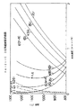
本発明に用いる供試鋼を設計するにあたって、前述の(α+γ)Fe相二相領域を安定に存在させるための条件を検討した。その結果を図1〜10に示した。各図中には(α+γ) Fe相二相領域のα相側組成をα/(α+γ)と表示し、γ相側をγ/(α+γ)と表示した。また、γ/(γ+θ)はセメンタイトと平衡するγ相の組成を示している。
【0038】
図1、図2は基本となるFe−Si−C、Fe−Al−C3元系の各縦断面の状態図を示したものであり、ほぼ2重量%以上のSi添加または0.7重量%以上のAl添加によって、(α+γ)Fe相二相領域がより炭素濃度(重量%)の広い範囲で、かつ800℃以上の温度域において安定に存在することがわかり、かつこれらの温度域においてはα相の存在による塑性加工時の変形抵抗の顕著な低下が起こり、優れた塑性加工性が確保できることがわかる。
【0039】
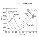
なお、Fe−Si2元系合金において5重量%以上のSiが添加されると急激に脆化するために、本発明ではSiの添加量を4.5重量%を上限とした。AlについてもSiとほぼ同じ作用があるが、製鋼上のAlの大量添加は介在物の巻き込みや発生の観点から現実的でないので、本発明ではSi+Alの総量が4.5重量%を越えないようにした。また、前述したように、歯車の浸炭浸窒でAlNを分散析出させ、耐面圧強度を高めるための量的な観点からAl添加量を0.1〜1.5重量%の範囲に限定した。なお、この際の炭素添加量は図1中のA点を基準に0.35重量%以下とした。塑性加工性を考慮する場合には塑性変形時のα相の体積%が25%以上であることが好ましいので、炭素量は0.25重量%がより好ましいが、後述するようにMo,Cr,V等の合金元素を複合添加することによって(α+γ)Fe相二相領域がより高炭素濃度側にまで拡大することを勘案してCは0.35重量%以下とした。また、Si添加量の下限値は、例えば図3,4,5,6に示したようにCr,Vの添加によって(α+γ)Fe相二相領域が拡大され、Siの代替効果を持つことおよびAlの複合添加によって、Si添加量は軽減されるが、コスト的な観点から安価なSiをできるだけ効率的に利用することが好ましい。
【0040】
また、 Cr,VはFeとの金属間化合物を作らず、かつSiと違って炭素,窒素との結合力が強く、図5に示したように(α+γ)Fe相二相領域を効果的に拡大,安定化させる元素であり、特にCrは熱間の塑性変形抵抗を高めない元素であることから、添加量の上限値はコストの観点から15重量%まで添加することが効果的と考えられる。また、Vは2重量%の効果がほぼCrの15重量%効果に近いことおよびコスト的な観点からも、その上限添加量は2重量%であることが好ましい。
【0041】
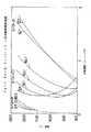
図7は、(α+γ)Fe相二相領域の拡大作用に対するMoとVの影響を示したものであり、明らかにMoはV等に較べて作用が小さい。従って、Moは前述の浸炭,浸炭浸窒,浸窒などの後の焼き入れ性を確保する目的とコスト的な観点から、上限添加量を1.0重量%とすることが好ましい。
【0042】
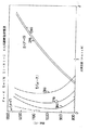
図8,9,10はMn,Ni,Cuの影響を示したものであるが、これらの元素は(α+γ)Fe相二相領域を縮小させるため、多量の添加は避ける必要があるが、Mn,Ni,Cuそれぞれの元素の総量が3重量%以下であることが好ましい。
【0043】
以上の設計条件のもとに用いた供試鋼と比較材との成分を表1にまとめて示した。
【0044】
【表1】

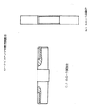
2)鍛造試験
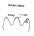
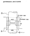
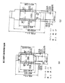
鍛造試験で対象とする歯車は、図11に示されているように、後述の動力循環式歯車試験機(以後FZGと呼ぶ)に供する歯車(図13(a))が取り出せるように、歯先部分に大きなR部(R=1.25mm)を設けるようにした。鍛造用には500トン油圧プレスを用い、鍛造前素材は図12の▲1▼に示される円柱材として、黒鉛潤滑剤を薄く塗布し、1000℃に高周波加熱した後に、図12のようにすえ込みながら歯出しを行った。なお、試験材としては表1のNo.3鋼材を中心に実施した。鍛造後の歯車精度は歯先径を中央部と中央部から±20mm位置で測定して評価した。結果を表2に示したが、SCM418の比較材との例において明らかなように、極めて優れた成形性を示し、歯先部への充填不良などが全く無く、成形圧力も比較材の5割程度で済むなどの効果が認められた。なお、No.1材の1100℃で1時間加熱した後に焼き入れた金属組織を図14に示したが、結晶粒は微細な状態にあることが確認される。
【0046】
【表2】
3)熱処理
この歯車素材は、図13(a)の形状に機械加工を追加して、浸炭,浸炭浸窒熱処理テストを実施した。
【0048】
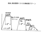
(1)浸炭,浸炭浸窒テスト1
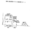
RXガス浸炭炉を用いて図15に示される熱処理を施した後に、歯車の歯形歪みを調査して、熱処理歪みを調査した。結果を表3に示したが、比較材に較べて明らかに低歪み処理化されていることがわかった。
【0049】
【表3】
なお、850℃での浸炭浸窒処理は、歯車表面相にAl,Cr,Vの窒化物および炭窒化物を微細に析出させるためのものである。また、930℃での浸炭期においては、表1に記載のCrを高濃度に含有するNo.4材においては平均粒径が約0.2ミクロンの微細なCr7C3型のCr炭化物が微細に析出することを確認した。ただし、図15の熱処理パターンでは930℃から850℃への炉内冷却中に粒界に板状の炭化物が顕著に析出するため、浸炭後に一旦急冷して板状炭化物の析出を防止することが必要である。同様のことはVを高濃度に含有するNo.5材についても適用することが好ましい。
【0051】
なお、浸窒による窒化物の分散析出を迅速に実施する目的で浸窒温度を950℃,1000℃で追加して確認した結果、1000℃においては最表面相に窒素ガスによると考えられるボイドの発生が確認されたので、アンモニア分解ガスを使った窒素拡散浸透処理は1000℃未満の温度で実施され、950℃以下の温度で実施することがより好ましいことが分かった。
【0052】
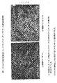
図16はNo.3材の表面層の金属組織を示したものであるが、析出するAlNによって針状マルテンサイト葉が微細で、かつイレギュラーになっており、また残留オーステナイトの高濃度に生成されていることがわかる。なお、この時の残留オーステナイト量はX線法によって約49体積%であることがわかっている。また、後述のローラピッチングテスト途中のNo.3材の表面層と表面から400μm位置での金属組織を走査型電子顕微鏡で観察した結果を図17(a),(b)に示したが、表面層の残留オーステナイトからさらに生成されるマルテンサイト葉が平均粒径0.2μm以下の高密度に分散析出したAlNによって、顕著に微細化されていることがわかる。
【0053】
なお、後述のローラピッチングテスト後においても残留オーステナイトは20〜30体積%以上に残留しており、比較材の残留オーステナイト量が50〜60体積%から転動後には5〜7体積%程度に減少していることから、AlNなどの微細な析出物によって残留オーステナイトが顕著に安定化され、このことが面圧強度の向上に対しても大きな役割を持つことがわかる。
【0054】
(2)浸炭,浸炭浸窒テスト2
真空浸炭炉を用いて図18に示した浸炭処理後にガス冷却を実施して、さらに850℃での浸窒処理を行った。これは高Cr,高Vを含有する鋼材に対して、前述の理由から不可欠の処理と考えたからである。なお、真空浸炭時の炭素活量はほぼ1の状態で、炭素ポテンシャルにすると約1.7重量%の条件で浸炭されており、従来の浸炭サイクルで実施される拡散期を実質的に設定しないで浸炭期のみの浸炭を行っている。
【0055】
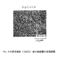
図19には真空浸炭後の表面炭素濃度分布を示した。比較材では粗大セメンタイトの析出による顕著な炭素の濃化が認められるのに対して、本発明のNo.1,No.3材では粗大セメンタイトの析出が防止されていることがわかる。また、No.5材ではVの添加によってNo.1,No.3材よりわずかに炭素の濃化が確認され、さらに、No.4材ではCr7C3炭化物による顕著な炭素の濃化が確認できる。図20はNo.4材の浸炭冷却後における最表面層近傍の金属組織を示したものであるが、前述のように非常に微細なCr炭化物が均一にかつ高密度に分散析出しているが、粗大なセメンタイトの析出が防止されていることがわかる。
【0056】
本実施例のように、従来の浸炭温度930℃での浸炭期の炭素ポテンシャル1.2重量%以上で、炭素活量ほぼ1となるような条件においても前述の粗大セメンタイトの析出を防止できる鋼を用いることによって、実質的な拡散期を設けないで迅速に浸炭させた後に、一旦冷却してから再加熱焼き入れもしくは浸炭浸窒−焼き入れして微細な炭化物,窒化物,炭窒化物を析出させて面圧強度を高める方法は浸炭コストの大幅な低減につながり、かつ後述のように面圧強度を高める手段として有効であることがわかる。
【0057】
また、 SiとAlの添加量を1.5重量%以上に設定することによって4重量%未満のCrの添加によって浸炭時に析出する粗大セメンタイトを完全に防止するとともに、かつCr添加量が4重量%以上においてはセメンタイトが析出せずに微細なCr炭化物(Cr7C3型)が析出するように設計しているNo.4材のような場合には、転動強度だけでなく、耐摩耗性の改善という点からも好ましい。
【0058】
なお、浸炭によって析出分散するCr7C3炭化物とオーステナイト間のV元素の分配係数を実測した結果、Vはオーステナイト母相中のV濃度で約15重量%の濃度でCr7C3に顕著に濃縮することがわかった。従って、本発明のCrの上限値15重量%を添加して、浸炭によって析出するCr7C3をより微細化させて表面層に優れた耐面圧特性を付与するときに、効率的に添加すべきV添加量の最大値は近似的に、
▲1▼約35体積%のCr7C3が析出すること、
▲2▼Vの分配係数が15であり、これからオーステナイト母相中でのV濃度が求まること、
▲3▼さらに、Cr7C3炭化物と平衡するオーステナイトの炭素濃度が約1重量%と近似でき、VCの固溶度積からオーステナイトに固溶し得る最大V濃度が約0.35重量%と求まるので、
鋼中の合金元素としては約1.8重量%の添加ができ、それ以上のVはVCとして更に析出することになる。なお、前述の(α+γ)Fe相二相領域の拡大に対する好ましいV添加量とも良く符合するので本発明でのVの上限添加量を2重量%以下とした。
【0059】
4)面圧強度評価結果
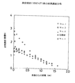
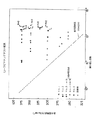
(1)ローラピッチングテスト
図21に示した小ローラに供試鋼を加工した後に、No.1,2,3および比較材は前述の図15の熱処理を施し、さらに、No.4,5材は図18の熱処理を施して面圧試験に供した。また、ローラピッチングテスト用の大ローラにはSUJ2を焼き入れ焼き戻し、硬度をHRC64に調整したものを使用した。
【0060】
テスト条件は回転数1050rpm,滑り率−40%,面圧を250〜375kg/mm2の範囲において適時調整して行った。なお潤滑油にはEO30を使い、油温度は80℃に調整し行った。ピッチング発生の判定は小ローラにピッチが1個発生するまでの回転数で評価した。
【0061】
以上の条件で実施した結果を図22に示した。なお、図中の☆と▼印はNo.3とNo.4の小ローラ表面を約100μm除去した小ローラを用いて実施した結果であり、No.3では著しい耐面圧強度が劣化していることがわかった。
【0062】
以上のことから、まずNo.1,2,3,5と比較材の結果を比較すると、ほぼ1重量%AlまではAlの添加量とともに耐面圧強度が改善され、この原因が微細なAlNの析出効果にあることが分かった。また、No.4の高Cr材ではAlNの添加よりも約20体積% Crの特殊炭化物が微細に分散析出したことによる効果が顕著に発揮されていることが分かった。
【0063】
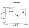
(2)動力循環式歯車試験
動力循環式歯車試験機(FZG)を用いてNo.3材、比較材の面圧、歯元強度を評価した。またFZG試験での相手歯車は同一材料で同一の熱処理を施した図13(b)のものを使用した。なお、FZG試験条件は回転数2000rpmで歯車面圧が200〜300kg/mm2で適時調整して実施した。ピッチング゛発生条件はそのピッチングによって振動が検知できる歯車噛み合い数としたが、実際にはピッチング発生時には歯車内には2個以上のピッチングが観察された。なお、使用した潤滑油はEO30であり、油温度は80℃に調整して使用した。
【0064】
上述のピッチング発生の前後において、歯車が歯元から折損することはなく、実質的な歯元強度に問題がないことが分かった。
【0065】
No.3材,比較材の面圧強度結果を図23に示したが、Al添加による耐面圧強度の向上が極めて顕著に確認され、上述のローラピッチングテストの結果と良く符合していることが分かった。
【0066】
本発明によれば、塑性加工性の優れた歯車素材を容易に得ることでき、後の機械加工の省力化に大きく寄与するとともに、AlNおよびCr炭化物などの微細な分散とマルテンサイトの微細化によって極めて面圧強度に優れた歯車部材やその他多くの転動部材を提供することができた。さらに、実質的にはSi+Alの添加によって炭素活量がほぼ1の高炭素ポテンシャル条件においても、粗大セメンタイトが析出することを防止して、極めて迅速な浸炭を可能にして、歯車部材や他の多くの転動部材の熱処理コストの低減が可能となった。
【図面の簡単な説明】
【図1】図1は、Fe−Si−C3元系縦断面状態図である。
【図2】図2は、Fe−Al−C3元系縦断面状態図である。
【図3】図3は、Fe−Cr−C3元系縦断面状態図である。
【図4】図4は、Fe−2wt%Si−Cr−C4元系縦断面状態図である。
【図5】図5は、Fe−3wt%Si−C−Cr,−V 4元系縦断面状態図である。
【図6】図6は、Fe−4.5wt%Si−Cr−C4元系縦断面状態図である。
【図7】図7は、 Fe−4.5wt%Si−C−Mo ,−V4元系縦断面状態図である。
【図8】図8は、Fe−4.5wt%Si−Mn−C4元系縦断面状態図である。
【図9】図9は、Fe−4.5wt%Si−Ni−C4元系縦断面状態図である。
【図10】図10は、Fe−4.5wt%Si−Cu−C4元系縦断面状態図である。
【図11】図11は、鍛造用歯車の概略図である。
【図12】図12は、歯車用鍛造前素材と鍛造方法説明図である。
【図13】図13は、動力循環式歯車試験用歯車を示す図である。
【図14】図14は、1100℃,1時間加熱後のNo.1材の結晶粒の金属組織を示す図である。
【図15】図15は、浸炭,浸炭浸窒テスト1の熱処理パターンである。
【図16】図16は、図15の熱処理を施したNo.3材の表面金属組織を示す図である。
【図17】図17(a),(b)は、それぞれ図15の熱処理を施したNo.3材のローラピッチングテスト途中での表面および0.4mm位置での金属組織を示す図である。
【図18】図18は、浸炭,浸炭浸窒テスト2の熱処理パターンである。
【図19】図19は、真空浸炭後のNo.1,3,4および比較材の表面層における炭素濃度分布である。
【図20】図20は、図18の1050℃浸炭後のNo.4材の表面金属組織を示す図である。
【図21】図21は、ローラピッチングテスト用試験テストピースを示す図である。
【図22】図22は、ローラピッチングテスト結果を示す図である。
【図23】図23は、動力循環式歯車試験結果を示す図である。[0001]
BACKGROUND OF THE INVENTION
The present invention provides a rolling member manufacturing method for producing a rolling member such as a high-strength gear by performing surface heat treatment such as carburizing and carburizing and nitriding, and a manufacturing method of the rolling member that is excellent in plastic workability. The present invention relates to a rolling member.
[0002]
[Prior art]
In recent years, gears and the like used in automobiles and construction machines have been required more than ever to improve cost by reducing processing time and to improve surface pressure resistance for downsizing a power transmission device. Among these, from the viewpoint of reducing processing time, when manufacturing a blank material by conventional hot forging, in order to improve the problem that the dimensional accuracy of the material is poor and the amount of cutting by machining is large, cold forging Many high-precision forging methods have been studied. Also, from the viewpoint of improving the surface pressure resistance strength, in order to improve the temper softening resistance of the steel, it is hardened after positive addition of Mo element, carburization, carburizing and nitrocarburizing heat treatment, and shot peening is performed actively. Many studies have also been made on methods for increasing the hardness of the surface layer and imparting significant compressive residual stress.
[0003]
[Problems to be solved by the invention]
When gear set-up is performed by hot forging, the heated material is rapidly cooled when a γ-phase (austenite) steel heated to 1200 to 1300 ° C. is placed in a forging die at room temperature. , A sudden increase in deformation resistance occurs, and when forming a precise tooth profile, it generates significant stress on the mold and causes significant wear on the mold. It is difficult to produce precise forged blanks for gears by having a sufficient R section and by significantly increasing the mold temperature to suppress cooling due to contact with the mold. is there. Although it is considered that the forging speed is increased and the blank of the forged material is prevented from being cooled by the shearing heat generation of the forged material, on the other hand, this further increases the deformation resistance. There is a problem in aiming for more precise forging.
Further, in a more compact gear, the tooth profile is particularly small, and the gear is more easily cooled, so that the above-described problems become more apparent.
[0004]
Furthermore, attempts have been made to implement gear gearing with high accuracy by cold forging a hot forging material, but there is a problem in that it leads to a significant cost increase due to the two-time process.
[0005]
Moreover, since the gear material is once heated to 1200 to 1300 ° C. in the above hot forging, the austenite phase crystal grains become very coarse, and the forging material has a deformation resistance in the rapid cooling part and the other part. In order to prevent the distortion of gears after subsequent machining and carburizing heat treatment as much as possible, because the difference becomes large and machining distortion tends to remain inhomogeneous, many of them are sized by cooling normalization before machining. And distortion removal have been implemented, resulting in increased costs.
[0006]
In addition, from the above viewpoint, the material is heated to a temperature of 850 to 1000 ° C. lower than the hot forging temperature, and the steel is in the (α + γ) Fe phase two-phase structure region during forging, with the help of the α phase. A warm forging method has also been attempted in which the deformation resistance is lowered and the forging is performed quickly with high accuracy. However, since the α-phase is precipitated from the γ-phase grain boundary, it is subjected to strong processing, In some cases, there is a danger that grain boundary separation occurs and the material becomes brittle.
[0007]
In recent gear reduction gears and transmissions, as a trend toward higher output and lighter weight and compactness, improvement of characteristics excellent in surface pressure resistance is demanded particularly in gears. In general, gears are used after being machined and subjected to surface heat treatment such as carburizing and carburizing and nitriding to harden the surface layer and to withstand high contact surface pressure (Hertz surface pressure). However, these heat treatments usually take a long time, and with gears and the like, the cost becomes high and becomes a problem. In particular, there are many large gear reduction gears for construction machines, and it is not uncommon for ordinary RX gas carburizing to take a few days. For example, various attempts have been made to increase the carburizing temperature. However, in order to increase the RX gas carburizing temperature, it is very difficult to control the carbon potential during carburizing with CO / CO2 gas equilibrium. For example, during the carburizing period with a high carbon potential, From the viewpoint of preventing coarse cementite from depositing and deteriorating the gear strength, and also from the viewpoint of preventing the precipitation of these cementite, a long diffusion period equal to or greater than the carburizing period is provided to reduce the surface carbon concentration. Although optimization is attempted, it is problematic because accurate control of the carbon potential is difficult as described above.
[0008]
Furthermore, from the above-mentioned trend, in order to manufacture gears that can withstand higher contact surface pressure, recently, Mo, V, and crystal grains that increase the resistance to temper softening of the hardened surface layer after quenching into the steel used are used. Addition of Nb, Ti, etc. to reduce the size of the alloy has been attempted in terms of alloy design, and in addition, strong shot peening has been applied to harden the surface hardened layer, but it is not always sufficient Has not been effective.
[0009]
In addition, positive addition of an element that forms fine special carbides in austenite such as V, Nb, and Ti from the viewpoint of strengthening the gear significantly increases the deformation resistance of austenite at high temperatures, and is not necessarily described above. It is also a problem that the alloy design considering the plastic workability is not made.
[0010]
The present invention has been made in view of the above-described problems, and in producing a shaped material that is easily laid out using a plastic working method instead of machining a high-strength gear or the like, In addition to reducing deformation resistance during processing, we provide steel materials and rolling members that enable stable and accurate plastic processing at lower temperatures, and are subjected to surface heat treatment such as carburizing and carburizing and nitrogenizing. Thus, an object of the present invention is to provide a method for producing a rolling member such as a gear having excellent surface pressure strength.
[0011]
[Means for solving the problems and actions / effects]
In order to solve the above-mentioned problems at the time of hot forging, in the present invention, in the temperature range of 800-1300 ° C., at least in the temperature range of 850-1200 ° C., the structure in the heated state before forging is αFe phase and / or ( (α + γ) Fe phase two-phase region is stably present, and at the time of forging, a steel material in which the alloy components are adjusted so that at least the α phase in the (α + γ) Fe phase two-phase region is 25% by volume or more, Prevents an increase in deformation resistance by stabilizing the (α + γ) Fe phase two-phase region in a wide temperature range even if it is plastically processed with low deformation resistance and cooling occurs due to contact with the mold during forging, This improves the plastic workability.
[0012]
As described above, in the temperature range of 850 to 1200 ° C., the adjustment of the alloy component for stabilizing the microstructure in the heated state before forging so as to be in the αFe phase and / or the (α + γ) Fe phase two-phase region is the α phase. The total amount of Si and Al, which are stabilizing elements, is 1.0 to 4.5% by weight, Al is 0.1 to 1.5% by weight, and carbon (γ-phase stabilizing element) is 0.35% by weight. The adjustment was made within the following range.
[0013]
The crystal grains in the (α + γ) Fe phase two-phase region when heated to 1100 to 1300 ° C., which is the maximum temperature of 1000 ° C. or higher that can suppress the growth of conventional γFe phase crystal grains, are the conventional austenitic single-phase steel. The growth was extremely suppressed compared to the conventional crystal grains, and the problems related to the coarsening of the crystal grains during conventional forging heating and further to the coarsening of the crystal grains when the temperature of carburization described later was raised were solved.
[0014]
Furthermore, the brittleness problem that occurs during the above-mentioned conventional warm forging is that the initial state of forging is set in the (α + γ) Fe phase two-phase region, and the amount of α phase during forging is adjusted to 25% by volume or more. By doing so, deformation at the γ phase grain boundary and concentration of stress were avoided, and as a result, the brittleness problem of grain boundary separation was solved.
In addition, quenching distortion when machined after forging and quenching after carburizing and / or carburizing and nitrocarburizing heat treatment can be greatly reduced by the fact that many internal structures below the surface hardened layer are composed of α-phase, which increases the gear height. The accuracy was improved.
[0015]
In order to improve carburizing costs, it is most effective to increase the temperature of carburizing as in the past. In the present invention, coarse cementite precipitates on the steel surface due to carburizing and carburizing and nitriding even when the carbon potential is Acm. To solve this problem, the total amount of Si + Al in the steel component was adjusted to 1.0% by weight or more. Furthermore, it is cooled at a speed at which coarse grain boundary cementite does not precipitate directly in the carburized layer from this carburizing temperature at a high temperature, and re-heating treatment below the carburizing temperature is performed to disperse and precipitate fine cementite. By reducing the size of the austenite crystal grains, we established a technology to increase the surface pressure strength, thereby making it possible to eliminate the diffusion period in carburizing and reducing the carburizing cost significantly. Although direct cooling from the high-temperature carburizing temperature is preferable to reduce the thermal distortion of the gear, gas cooling is preferable in the present invention. However, in the present invention, the structure inside the carburized layer is as described above from the (α + γ) Fe phase. This is a preferable alloy design.
[0016]
In addition, in members that require more remarkable wear resistance and surface pressure strength, it may be effective to disperse and precipitate a large amount of fine Cr7C3 during high-temperature carburization by appropriately adding Cr, When carburized into a normal high Cr alloy, Cr7C3 carbide precipitates finely except for the outermost surface layer of the carburized layer, but coarse cementite precipitates at a high concentration on the outermost surface portion of the carburized layer, and is significantly embrittled. There is a problem to do. On the other hand, in the present invention, as described above, the precipitation of coarse cementite is prevented by increasing the amount of Si, Si + Al to 1.5% by weight or more. Preferably, the concentration of Si, Si + Al is 2.5% by weight or more from the relationship with the stability range of the (α + γ) Fe phase two-phase region described above. Further, the Cr addition amount is examined from the relationship with the wear resistance. However, since a common hard dispersed phase ratio becomes brittle when it is 35% by volume or more, the upper limit is 15 wt% Cr in the present invention. .
[0017]
Al that stabilizes the αFe phase in the same way as Si as a means to further increase the surface pressure strength of the rolling member and bonds strongly with nitrogen that diffuses and penetrates from the surface by carburizing and nitriding treatment to form AlN nitride. Is added in the range of 0.1 to 1.5% by weight, so that approximately 6 volumes of AlN having an average particle size of 0.5 μm or less are contained in the surface layer by carburizing and / or nitriding. Excellent properties were obtained by dispersing and precipitating with the upper limit of%. In addition, excellent surface pressure strength was obtained by adjusting the dispersion precipitation depth of AlN to 0.05 times mm or more of the gear module.Here, the “surface layer” refers to a layer formed at the penetration depth when one or more of carbon and nitrogen are diffused and penetrated from the surface.
[0018]
Further, in order to increase the surface pressure strength and tooth root strength of the gear, the present invention applies the carburizing and / or carburizing / nitrocarburizing method almost in accordance with the conventional gear design standard, and at least the diffusion depth of carbon is the gear module. It ensured by heat-processing so that it might become 0.15 times mm or more.
[0019]
The amount of carbon to be diffused and infiltrated is preferably 0.6% by weight or more in terms of surface carbon concentration, and when carbide (such as cementite) is precipitated in the surface layer, the average particle size of the carbide is determined. The surface carbon concentration is preferably 2.0% by weight, adjusted to 3 μm or less.
When Cr is added at a high concentration to disperse 35% by volume of Cr7C3 carbide, the upper limit of the surface carbon concentration is about 4.5% by weight.
[0020]
Furthermore, the alloy of the present invention does not precipitate coarse cementite even in the carburizing period when the carbon activity is approximately 1 compared to the conventional case-hardened steel, and stable and high-concentration carburization is possible at a high carbon potential. It has been improved to be able to. Therefore, as a method of dispersing and precipitating fine cementite, after cementation and / or carburizing and nitriding, the cementite is dispersed and precipitated once in the course of reheating after cooling to below A1 temperature or near room temperature, and at the reheating temperature for quenching. It is preferable to quench from a state in which is not dissolved yet.
[0021]
The steel structure inside the hardened surface layer after quenching after heat treatment such as carburizing and carburizing and nitrocarburizing is composed of α phase and one or more of pearlite, martensite, and bainite. Thus, since it becomes 25% by volume or more, it is preferable to increase the strength of the α phase from the viewpoint of the strength of the substrate. In the present invention, it is improved by solid solution strengthening of αFe phase such as Si and Al. However, from the viewpoint of further strengthening, it is preferable to increase the amount of martensite and / or bainite, so Cr, Mn, It was improved by adding an appropriate amount of alloying elements such as Ni and Mo that enhance the hardenability.
[0022]
Cr is an element that stabilizes the αFe phase, and is an element that expands the above-mentioned (α + γ) Fe phase two-phase region, and has the effect of remarkably preventing the graphitization of cementite and improving the hardenability. Although it is possible to add in a wide composition range, the lower limit addition amount is preferably 0.3% by weight or more in order to prevent cementite from being graphitized by Si, Al added at a high concentration. The addition amount is preferably 15% by weight or less from the viewpoint of an increase in deformation resistance during plastic working and cost.
[0023]
Mn and Ni are elements stabilizing the γFe phase and are elements that reduce the (α + γ) Fe phase two-phase region, but are preferably added in an amount of 2% by weight or less from the viewpoint of improving hardenability.
[0024]
Mo is an alloy element that exhibits almost the same action as Cr, but it works particularly on improving hardenability and resistance to temper softening, but is added within a range of 1% by weight or less from the viewpoint of cost. It is preferable.
[0025]
B hardly affects the above-mentioned phase equilibrium, but it is preferably added to the extent of conventional boron treatment from the viewpoint of improving hardenability.
[0026]
V is an αFe phase stabilizing element similar to Si, and is an element that expands the (α + γ) Fe phase two-phase region, and strongly bonds to carbon and nitrogen that diffuses and penetrates during carburizing and / or carburizing and nitriding. In view of the action of dispersing and precipitating fine special carbides, nitrides, and carbonitrides, it is preferable to be added at 2% by weight or less.
[0027]
Furthermore, Zr, Ti, and Nb are added in the range of conventional additions because they suppress the growth of crystal grains when the gear surface layer part is austenitized by diffusion and permeation of carbon and nitrogen during carburizing and carburizing and nitriding. It is preferable.
[0028]
Ca, S, and Pb are usually added mainly for the purpose of improving machinability. For such a purpose, it is preferable to add and use within the usual range.
[0029]
As described above, a large amount of retained austenite is formed in the surface layer that has been hardened and hardened after diffusion of carbon and carbon by carburizing, carburizing and nitriding, and nitriding. Although it is controlled by the C, N concentration and the alloy element concentration, it can also be controlled by shot peening, sub-zero treatment, etc. as in the conventional open technology. In that case, a large compressive residual stress is generated in the surface layer portion, and it is known that it contributes to the improvement of the bending strength of the tooth base particularly in gears, and shot peening can be applied also in the present invention. is there.
[0030]
In addition, by applying reheating and quenching to the surface layer in which fine precipitates are dispersed by carburizing, carburizing and nitriding as described above, the prior austenite crystal grains in the surface layer are significantly more than ASTM No. 9 or higher. Miniaturization is very preferable in terms of strength.
[0031]
Furthermore, as described above, the crystal grains are remarkably refined, and fine precipitates such as AlN having an average grain size of 0.5 μm or less are dispersed at a high density, so that lenticular martensite leaves and rolling after quenching can be obtained. Remarkably irregularities in the linearity of martensite leaves produced from retained austenite, and refined to an average leaf width of 1 μm or less on average, delaying intragranular fatigue cracks, for example, and concentrating on martensite leaves This is very preferable because the stress to be dispersed can be dispersed very efficiently.
[0032]
According to the present invention, by adjusting the basic components Si, Al and C, the αFe phase and the (α + γ) Fe two-phase region are stably present in a wide temperature range, and the deformation resistance during forging is reduced. As a result of improving the forging formability, it is possible to increase the dimensional accuracy of the blank material after forging and to form a near-net-shaped gear.
[0033]
Furthermore, after carburizing, carburizing and nitriding this material and dispersing fine nitrides mainly composed of Al and Cr, the surface pressure strength of the hardened gear is the same as the carburized and hardened gears of conventional case-hardened steel. It was strengthened to more than 1.4 times the surface pressure strength.
[0034]
In addition, the amount of heat treatment distortion after carburizing / quenching of gears compared to the amount of distortion of gears carburized / quenched in conventional case-hardened steel is markedly improved by the fact that most of the internal structure of the surface layer is made of αFe phase. It became clear that.
[0035]
Also, vacuum carburization at a high temperature at 1100 ° C. is performed in comparison with conventional case-hardened steel, and as a result, the carbon activity is always carburized in a state of approximately 1, and even under conditions that do not have a substantial diffusion period. It was found that the coarse carbonite does not precipitate on the surface layer, the surface carbon concentration is high, a stable carbon concentration distribution is obtained, and the carburizing time can be significantly shortened. Especially in this case, the carburization time can be shortened significantly by applying gas cooling after carburizing and once cooling it to near room temperature, and then finely dispersing and precipitating cementite by reheating to reduce the carburizing time. It has been found that this leads to a significant reduction in
[0036]
【Example】
Next, specific examples of the rolling member and the manufacturing method thereof according to the present invention will be described with reference to the drawings.
[0037]
1) Preparation of steel
In designing the test steel used in the present invention, the conditions for allowing the aforementioned (α + γ) Fe phase two-phase region to exist stably were examined. The results are shown in FIGS. In each figure, the α phase side composition of the (α + γ) Fe phase two-phase region is expressed as α / (α + γ), and the γ phase side is expressed as γ / (α + γ). Also, γ / (γ + θ) indicates the composition of the γ phase that is in equilibrium with cementite.
[0038]
FIG. 1 and FIG. 2 show phase diagrams of the longitudinal sections of the basic Fe—Si—C and Fe—Al—C ternary systems, with Si addition of approximately 2% by weight or more or 0.7% by weight. With the above Al addition, it can be seen that the (α + γ) Fe two-phase region exists stably in a wider range of carbon concentration (% by weight) and in a temperature range of 800 ° C. or higher, and in these temperature ranges, It can be seen that the deformation resistance during the plastic working due to the presence of the α phase is remarkably lowered, and excellent plastic workability can be secured.
[0039]
In addition, in order to rapidly embrittle when 5 wt% or more of Si is added to the Fe—Si binary alloy, the upper limit of the amount of Si added is 4.5 wt% in the present invention. Al has almost the same effect as Si, but the addition of a large amount of Al on steelmaking is not realistic from the viewpoint of inclusion inclusion and generation, so in the present invention the total amount of Si + Al should not exceed 4.5% by weight. I made it. Further, as described above, AlN is dispersed and precipitated by gear carburizing and nitriding, and the amount of Al added is limited to a range of 0.1 to 1.5% by weight from the viewpoint of quantitatively increasing surface pressure resistance. . The amount of carbon added at this time was set to 0.35% by weight or less based on the point A in FIG. When considering the plastic workability, the volume percentage of the α phase at the time of plastic deformation is preferably 25% or more, so the carbon content is more preferably 0.25% by weight, but as will be described later, Mo, Cr, In consideration of the fact that the (α + γ) Fe phase two-phase region is expanded to the higher carbon concentration side by complex addition of alloy elements such as V, C is set to 0.35 wt% or less. In addition, the lower limit value of the Si addition amount is, for example, as shown in FIGS. Although the amount of Si added is reduced by the combined addition of Al, it is preferable to use inexpensive Si as efficiently as possible from the viewpoint of cost.
[0040]
In addition, Cr and V do not form an intermetallic compound with Fe, and unlike Si, the bonding strength with carbon and nitrogen is strong. As shown in FIG. 5, the (α + γ) Fe phase two-phase region is effectively formed. It is an element that expands and stabilizes. In particular, Cr is an element that does not increase hot plastic deformation resistance. Therefore, it is considered effective to add the upper limit of the addition amount to 15% by weight from the viewpoint of cost. . Further, V has an upper limit of 2% by weight because the effect of 2% by weight is almost the same as the 15% by weight effect of Cr and from the viewpoint of cost.
[0041]
FIG. 7 shows the influence of Mo and V on the expansion action in the (α + γ) Fe phase two-phase region. Clearly, Mo has a smaller action than V or the like. Therefore, it is preferable that the upper limit addition amount of Mo is 1.0% by weight from the viewpoint of securing the hardenability after carburizing, carburizing, nitriding, nitriding, and the like and the cost.
[0042]
FIGS. 8, 9, and 10 show the influence of Mn, Ni, and Cu. Since these elements reduce the (α + γ) Fe phase two-phase region, it is necessary to avoid adding a large amount. The total amount of each element of Ni, Ni and Cu is preferably 3% by weight or less.
[0043]
Table 1 summarizes the components of the test steel and the comparative material used under the above design conditions.
[0044]
[Table 1]
2) Forging test
As shown in FIG. 11, the gear targeted for the forging test is a tooth tip so that a gear (FIG. 13A) used for a power circulation gear test machine (hereinafter referred to as FZG) described later can be taken out. A large R portion (R = 1.25 mm) was provided in the portion. A 500-ton hydraulic press is used for forging, and the material before forging is a cylindrical material shown in (1) of FIG. 12, and a graphite lubricant is thinly applied and heated to 1000 ° C. after high-frequency heating, and then, as shown in FIG. The teeth were set out while putting in. As test materials, No. 1 in Table 1 was used. It was carried out mainly on 3 steel materials. The gear accuracy after forging was evaluated by measuring the tooth tip diameter at the center and at a position ± 20 mm from the center. The results are shown in Table 2. As is clear in the example of the comparative material of SCM418, it shows extremely excellent formability, there is no filling failure in the tooth tip part, and the molding pressure is 50% of the comparative material. The effect such as being sufficient was recognized. No. FIG. 14 shows the metal structure quenched after heating at 1100 ° C. for one hour, and it is confirmed that the crystal grains are in a fine state.
[0046]
[Table 2]
3) Heat treatment
This gear material was subjected to carburizing and carburizing and nitrocarburizing heat treatment tests by adding machining to the shape of FIG.
[0048]
(1) Carburizing, carburizing and
After performing the heat treatment shown in FIG. 15 using an RX gas carburizing furnace, the tooth profile distortion of the gears was investigated to investigate the heat treatment distortion. The results are shown in Table 3, and it was found that the distortion was clearly reduced as compared with the comparative material.
[0049]
[Table 3]
The carbonitriding process at 850 ° C. is for finely depositing Al, Cr, V nitride and carbonitride on the gear surface phase. Further, in the carburizing period at 930 ° C., No. 1 containing Cr described in Table 1 at a high concentration. In the four materials, it was confirmed that fine Cr7C3 type Cr carbide having an average particle diameter of about 0.2 microns was finely precipitated. However, in the heat treatment pattern of FIG. 15, plate-like carbides are remarkably precipitated at the grain boundaries during cooling in the furnace from 930 ° C. to 850 ° C., so that the plate-like carbides can be prevented from precipitating by quenching once after carburizing. is necessary. The same is true for No. 1 containing V at a high concentration. It is preferable to apply also to five materials.
[0051]
In addition, as a result of adding and confirming the nitriding temperature at 950 ° C. and 1000 ° C. for the purpose of quickly carrying out the dispersion and precipitation of nitride by nitriding, at 1000 ° C., voids considered to be due to nitrogen gas in the outermost surface phase Since generation | occurrence | production was confirmed, it turned out that the nitrogen diffusion infiltration process using ammonia decomposition gas is implemented at the temperature below 1000 degreeC, and it is more preferable to implement at the temperature below 950 degreeC.
[0052]
FIG. It shows the metallographic structure of the surface layer of the three materials, but the acicular martensite leaves are fine and irregular due to the precipitated AlN, and it is generated at a high concentration of retained austenite. Recognize. The amount of retained austenite at this time is found to be about 49% by volume by the X-ray method. No. No. in the middle of the roller pitching test described later. 17A and 17B show the results of observation of the surface layer of the three materials and the metal structure at a position of 400 μm from the surface with a scanning electron microscope. Martensite further generated from the retained austenite of the surface layer It can be seen that the leaves are remarkably miniaturized by AlN dispersed and precipitated at a high density with an average particle size of 0.2 μm or less.
[0053]
Even after the roller pitching test described later, the retained austenite remains at 20 to 30% by volume or more, and the amount of retained austenite of the comparative material decreases from 50 to 60% by volume to about 5 to 7% by volume after rolling. Therefore, it can be seen that the retained austenite is remarkably stabilized by fine precipitates such as AlN, and this has a great role in improving the surface pressure strength.
[0054]
(2) Carburizing, carburizing and
Gas cooling was performed after the carburizing process shown in FIG. 18 using a vacuum carburizing furnace, and a nitrocarburizing process at 850 ° C. was further performed. This is because a steel material containing high Cr and high V is considered to be an indispensable treatment for the reasons described above. It should be noted that the carbon activity during vacuum carburization is approximately 1, and the carbon potential is carburized under the condition of about 1.7% by weight, and the diffusion period carried out in the conventional carburizing cycle is not substantially set. Carburizing is performed only during the carburizing season.
[0055]
FIG. 19 shows the surface carbon concentration distribution after vacuum carburization. In the comparative material, remarkable carbon enrichment due to the precipitation of coarse cementite is observed, whereas the No. of the present invention. 1, No. 1 It can be seen that the three materials prevent the precipitation of coarse cementite. No. In the case of 5 materials, no. 1, No. 1 A slight carbon concentration was confirmed from the three materials. In 4 materials, the remarkable carbon concentration by Cr7C3 carbide | carbonized_material can be confirmed. FIG. This shows the metal structure near the outermost surface layer after carburizing and cooling of the four materials. As described above, very fine Cr carbide is uniformly and densely dispersed, but the coarse cementite It can be seen that precipitation is prevented.
[0056]
As in this example, the above-mentioned coarse cementite precipitation can be prevented even under conditions where the carbon potential is 1.2% by weight or more in the carburizing period at a conventional carburizing temperature of 930 ° C. and the carbon activity is approximately 1. By using this, after carburizing rapidly without providing a substantial diffusion period, it is once cooled and then reheat quenching or carburizing nitrocarburizing-quenching to obtain fine carbides, nitrides, carbonitrides. It can be seen that the method of increasing the surface pressure strength by precipitating leads to a significant reduction in the carburizing cost and is effective as a means for increasing the surface pressure strength as will be described later.
[0057]
Further, by setting the addition amount of Si and Al to 1.5% by weight or more, coarse cementite precipitated during carburization is completely prevented by addition of less than 4% by weight of Cr, and the addition amount of Cr is 4% by weight. In the above, No. designed to precipitate fine Cr carbide (Cr7C3 type) without precipitation of cementite. In the case of four materials, it is preferable not only from the rolling strength but also from the viewpoint of improving the wear resistance.
[0058]
The distribution coefficient of V element between Cr7C3 carbide precipitated and dispersed by carburization and austenite was measured, and as a result, it was found that V was remarkably concentrated in Cr7C3 at a concentration of about 15% by weight in the austenite matrix. . Therefore, when the upper limit of 15% by weight of Cr according to the present invention is added and Cr7C3 precipitated by carburization is further refined to give excellent surface pressure resistance to the surface layer, V should be efficiently added. The maximum amount of addition is approximately
(1) About 35% by volume of Cr7C3 is precipitated,
(2) The V distribution coefficient is 15, and from this, the V concentration in the austenite matrix can be obtained.
(3) Further, the carbon concentration of austenite that is in equilibrium with Cr7C3 carbide can be approximated to about 1% by weight, and the maximum V concentration that can be dissolved in austenite can be determined from the solid solubility product of VC to be about 0.35% by weight.
As an alloying element in steel, about 1.8% by weight can be added, and more V is further precipitated as VC. In addition, since it agrees well with the preferable V addition amount for the expansion of the above-mentioned (α + γ) Fe phase two-phase region, the upper limit addition amount of V in the present invention is set to 2 wt% or less.
[0059]
4) Surface pressure strength evaluation results
(1) Roller pitching test
After processing the test steel on the small roller shown in FIG. 1, 2 and 3 and the comparative material were subjected to the heat treatment of FIG. The
[0060]
The test conditions were adjusted at an appropriate time in the range of 1050 rpm, slip rate -40%, and surface pressure in the range of 250 to 375 kg / mm2. The lubricating oil was EO30, and the oil temperature was adjusted to 80 ° C. The determination of the occurrence of pitching was evaluated by the number of rotations until one pitch is generated on the small roller.
[0061]
The results obtained under the above conditions are shown in FIG. In the figure, ☆ and ▼ are No. 3 and no. No. 4 is a result obtained by using a small roller from which the surface of the small roller is removed by about 100 μm. In No. 3, it was found that the significant surface pressure strength was deteriorated.
[0062]
From the above, first of all, Comparing the results of the comparative materials with 1, 2, 3, 5 and up to about 1 wt% Al, it was found that the surface pressure strength was improved with the addition amount of Al, and this was due to the precipitation effect of fine AlN. It was. No. In the high Cr material of No. 4, it was found that the effect of finely dispersing and precipitating about 20% by volume of Cr special carbides was more remarkable than the addition of AlN.
[0063]
(2) Power circulation type gear test
Using a power circulating gear tester (FZG), No. The surface pressure and tooth root strength of three materials and comparative materials were evaluated. In addition, the counterpart gear in the FZG test was the same as that shown in FIG. Note that the FZG test conditions were adjusted at appropriate times with a rotation speed of 2000 rpm and a gear surface pressure of 200 to 300 kg /
[0064]
It was found that the gear did not break from the tooth root before and after the occurrence of the above-mentioned pitching, and there was no problem in the substantial tooth root strength.
[0065]
No. The surface pressure strength results of the three materials and the comparative material are shown in FIG. 23, and it is confirmed that the improvement of the surface pressure strength strength due to the addition of Al is remarkably confirmed and agrees well with the result of the roller pitching test described above. It was.
[0066]
According to the present invention, a gear material excellent in plastic workability can be easily obtained, greatly contributing to labor saving of subsequent machining, and by fine dispersion of AlN and Cr carbide and refinement of martensite. It has been possible to provide gear members and many other rolling members that are extremely excellent in surface pressure strength. Furthermore, the addition of Si + Al substantially prevents the precipitation of coarse cementite even under high carbon potential conditions where the carbon activity is approximately 1, enabling extremely quick carburization, and gear members and many other It became possible to reduce the heat treatment cost of the rolling member.
[Brief description of the drawings]
FIG. 1 is a longitudinal sectional view of an Fe—Si—C ternary system.
FIG. 2 is a longitudinal sectional view of an Fe—Al—C ternary system.
FIG. 3 is a longitudinal sectional view of an Fe—Cr—C ternary system.
FIG. 4 is a longitudinal sectional view of an Fe-2 wt% Si—Cr—C quaternary system.
FIG. 5 is a longitudinal sectional view of an Fe-3 wt% Si—C—Cr, —V quaternary system.
FIG. 6 is a longitudinal sectional view of an Fe-4.5 wt% Si—Cr—C quaternary system.
FIG. 7 is a longitudinal sectional view of Fe-4.5 wt% Si—C—
FIG. 8 is a longitudinal sectional view of an Fe-4.5 wt% Si—Mn—C quaternary system.
FIG. 9 is a longitudinal sectional view of an Fe-4.5 wt% Si—Ni—C quaternary system.
FIG. 10 is a longitudinal sectional view of an Fe-4.5 wt% Si—Cu—C quaternary system.
FIG. 11 is a schematic view of a forging gear.
FIG. 12 is an explanatory view of a material before forging for gears and a forging method.
FIG. 13 is a diagram showing a power circulation gear test gear.
14 shows No. 1 after heating at 1100 ° C. for 1 hour. It is a figure which shows the metal structure of the crystal grain of 1 material.
FIG. 15 is a heat treatment pattern of carburizing and carburizing and
16 is a graph showing No. 1 subjected to the heat treatment of FIG. It is a figure which shows the surface metal structure of 3 materials.
17 (a) and 17 (b) are Nos. Obtained after the heat treatment of FIG. It is a figure which shows the metal structure in the surface and 0.4 mm position in the middle of the roller pitching test of 3 materials.
FIG. 18 is a heat treatment pattern of carburizing and carburizing and
FIG. 19 shows No. 1 after vacuum carburization. It is carbon concentration distribution in the surface layer of 1, 3, 4 and a comparative material.
20 is a graph showing No. 1 after carburizing at 1050 ° C. in FIG. It is a figure which shows the surface metal structure of 4 materials.
FIG. 21 is a diagram showing a test piece for a roller pitching test.
FIG. 22 is a diagram illustrating a roller pitching test result.
FIG. 23 is a diagram showing the results of a power circulation gear test.
Claims (8)
(1)αFe相領域または(α+γ)Fe相二相領域の加熱温度範囲を、少なくとも800℃以上1300℃以下に広く取れるようにして、目的の形状に素形材を塑性加工する際の変形抵抗を少なくできるようにすることと、
(2)転動部品の強度を高めるために実施する浸炭および/または浸炭浸窒時において、カーボンポテンシャルが1.2重量%以上の条件であっても、粗大セメンタイトが転動表面に析出しないようにすること、
の両目的を達成するため、Alを0.1〜1.5重量%、Siを2重量%以上の範囲で、かつSi+Alの添加総量が4.5重量%以下になるようにAl,Siを含有するとともに、Cを0.35重量%以下、Crを0.3〜15重量%、Mnを0.1〜3.0重量%、Moを0〜1.0重量%、Vを0〜2重量%で、かつMn+Ni+Cuの添加総量が3重量%以下になるようにし、残部がFeおよび不可避不純物からなる鋼材を用いて、浸炭および浸窒処理もしくは浸炭浸窒処理と焼き入れ処理とを施すことによって、表面層がαFe相を含まないマルテンサイトと残留オーステナイトからなる組織、内部が(α+γ)Fe二相領域から冷却され、α相とパーライト、マルテンサイト、ベイナイトの一種以上とからなる組織を有するとともに、表面層中に平均粒径が0.5μm以下のAlNを0.4〜6.0体積%微細に分散析出させることによって耐面圧強度を高めた転動部材を得ることを特徴とする転動部材の製造方法。An iron-based alloy steel,
(1) Deformation resistance when plastic forming a shaped material into a desired shape so that the heating temperature range of the αFe phase region or the (α + γ) Fe phase two-phase region can be widened at least 800 ° C to 1300 ° C To be able to reduce
(2) When carburizing and / or carburizing and nitriding to increase the strength of rolling parts, even if the carbon potential is 1.2 wt% or more, coarse cementite does not precipitate on the rolling surface. To
In order to achieve both of these objectives, Al and Si are added so that Al is in the range of 0.1 to 1.5% by weight, Si is in the range of 2% by weight or more, and the total amount of Si + Al is 4.5% by weight or less. While containing C, 0.35 weight% or less, Cr 0.3-15 weight%, Mn 0.1-3.0 weight%, Mo 0-1.0 weight%, V 0-2 Carrying and nitrocarburizing treatment or carburizing and nitriding treatment and quenching treatment are performed using a steel material consisting of Fe and unavoidable impurities in the balance so that the total amount of Mn + Ni + Cu is 3% by weight or less. the tissue surface layer is composed of martensite and residual austenite without the αFe phase and the interior is cooled from (α + γ) Fe two-phase region, alpha phase and pearlite, martensite, a structure consisting of one or more of bainite Yes Then Rolling, characterized in that to obtain the rolling member with enhanced resistance to surface pressure strength by an average particle diameter of 0.5μm or less of AlN of 0.4 to 6.0 vol% finely dispersed precipitates in the surface layer Manufacturing method of moving member.
Priority Applications (2)
| Application Number | Priority Date | Filing Date | Title |
|---|---|---|---|
| JP03377498A JP4100751B2 (en) | 1998-01-30 | 1998-01-30 | Rolling member and manufacturing method thereof |
| US09/237,233 US6309475B1 (en) | 1998-01-30 | 1999-01-26 | Rolling element and producing method |
Applications Claiming Priority (1)
| Application Number | Priority Date | Filing Date | Title |
|---|---|---|---|
| JP03377498A JP4100751B2 (en) | 1998-01-30 | 1998-01-30 | Rolling member and manufacturing method thereof |
Publications (2)
| Publication Number | Publication Date |
|---|---|
| JPH11222627A JPH11222627A (en) | 1999-08-17 |
| JP4100751B2 true JP4100751B2 (en) | 2008-06-11 |
Family
ID=12395807
Family Applications (1)
| Application Number | Title | Priority Date | Filing Date |
|---|---|---|---|
| JP03377498A Expired - Fee Related JP4100751B2 (en) | 1998-01-30 | 1998-01-30 | Rolling member and manufacturing method thereof |
Country Status (2)
| Country | Link |
|---|---|
| US (1) | US6309475B1 (en) |
| JP (1) | JP4100751B2 (en) |
Families Citing this family (30)
| Publication number | Priority date | Publication date | Assignee | Title |
|---|---|---|---|---|
| US6474751B1 (en) | 1995-12-26 | 2002-11-05 | Denso Corporation | Hydraulic circuit having a rotary type pump and brake apparatus for a vehicle provided with the same |
| US7438477B2 (en) | 2001-11-29 | 2008-10-21 | Ntn Corporation | Bearing part, heat treatment method thereof, and rolling bearing |
| JP3873741B2 (en) * | 2001-12-27 | 2007-01-24 | 日本精工株式会社 | Rolling bearing |
| JP4812220B2 (en) * | 2002-05-10 | 2011-11-09 | 株式会社小松製作所 | High hardness and toughness steel |
| JP2004076125A (en) * | 2002-08-21 | 2004-03-11 | Komatsu Ltd | Rolling member |
| JP4718781B2 (en) | 2003-02-28 | 2011-07-06 | Ntn株式会社 | Transmission components and tapered roller bearings |
| JP4390576B2 (en) * | 2003-03-04 | 2009-12-24 | 株式会社小松製作所 | Rolling member |
| JP4390526B2 (en) | 2003-03-11 | 2009-12-24 | 株式会社小松製作所 | Rolling member and manufacturing method thereof |
| JP2004301321A (en) | 2003-03-14 | 2004-10-28 | Ntn Corp | Bearing for alternator and bearing for pulley |
| JP2004293632A (en) * | 2003-03-26 | 2004-10-21 | Ntn Corp | Rolling bearing |
| JP4486411B2 (en) * | 2003-06-05 | 2010-06-23 | Ntn株式会社 | Cam follower with roller |
| AU2003244116A1 (en) * | 2003-06-12 | 2005-01-04 | Koyo Thermo Systems Co., Ltd. | Method of gas carburizing |
| JP4152283B2 (en) | 2003-08-29 | 2008-09-17 | Ntn株式会社 | Heat treatment method for bearing parts |
| US7384488B2 (en) * | 2003-09-18 | 2008-06-10 | Mahindra & Mahindra Ltd | Method for producing gears and/or shaft components with superior bending fatigue strength and pitting fatigue life from conventional alloy steels |
| EP1707831B1 (en) * | 2004-01-09 | 2012-02-01 | NTN Corporation | Thrust needle roller bearing, support structure receiving thrust load of compressor for car air-conditioner, support structure receiving thrust load of automatic transmission, support structure for nonstep variable speed gear, and support structure receiving thrust load of manual transmission |
| JP4540351B2 (en) * | 2004-01-15 | 2010-09-08 | Ntn株式会社 | Steel heat treatment method and bearing part manufacturing method |
| US7662240B2 (en) * | 2004-06-22 | 2010-02-16 | The Timken Company | Seal for worm gear speed reducer |
| JP2007046717A (en) | 2005-08-10 | 2007-02-22 | Ntn Corp | Rolling-contact shaft with joint claw |
| JP5198765B2 (en) * | 2006-12-28 | 2013-05-15 | 株式会社小松製作所 | Rolling member and manufacturing method thereof |
| JP5191710B2 (en) * | 2007-08-31 | 2013-05-08 | 株式会社小松製作所 | Gear and manufacturing method thereof |
| JP5185907B2 (en) * | 2009-03-25 | 2013-04-17 | 株式会社クボタ | Sealing device for rotating part of engine |
| KR101704849B1 (en) | 2009-08-07 | 2017-02-08 | 스와겔로크 컴패니 | Low temperature carburization under soft vacuum |
| US10053763B2 (en) * | 2011-06-02 | 2018-08-21 | Aktiebolaget Skf | Carbo-nitriding process for martensitic stainless steel and stainless steel article having improved corrosion resistance |
| US9617632B2 (en) | 2012-01-20 | 2017-04-11 | Swagelok Company | Concurrent flow of activating gas in low temperature carburization |
| JP5786764B2 (en) * | 2012-03-06 | 2015-09-30 | 新日鐵住金株式会社 | Manufacturing method of high carbon chromium bearing steel |
| BR112017000895A2 (en) | 2014-07-16 | 2017-11-21 | Nsk Americas Inc | bearing component, bearing, use of a bearing component, and use of a bearing |
| JP6759842B2 (en) * | 2016-08-15 | 2020-09-23 | トヨタ自動車株式会社 | Steel manufacturing method |
| US11624106B2 (en) | 2020-03-18 | 2023-04-11 | Caterpillar Inc. | Carburized steel component and carburization process |
| CN114962460A (en) | 2021-02-25 | 2022-08-30 | 斯凯孚公司 | Heat treated roller bearing ring |
| CN119899972A (en) * | 2025-01-23 | 2025-04-29 | 江苏奇锦工模具有限公司 | A production process of high-strength and high-toughness hot-working die steel |
Family Cites Families (7)
| Publication number | Priority date | Publication date | Assignee | Title |
|---|---|---|---|---|
| JPS61163246A (en) * | 1985-01-09 | 1986-07-23 | Kobe Steel Ltd | Steel for carbonitriding |
| JP2549039B2 (en) * | 1991-09-17 | 1996-10-30 | 新日本製鐵株式会社 | Carbonitriding heat treatment method for high strength gears with small strain |
| JPH05195161A (en) | 1992-01-13 | 1993-08-03 | Kubota Corp | Double layer heat resistant steel pipe excellent in carburization resistance |
| JPH07207412A (en) | 1994-01-17 | 1995-08-08 | Sanyo Special Steel Co Ltd | Grain-stabilized carburizing steel |
| JPH08120438A (en) * | 1994-10-19 | 1996-05-14 | Kobe Steel Ltd | Production of parts for machine structure |
| JP2790788B2 (en) * | 1995-10-11 | 1998-08-27 | トーア・スチール株式会社 | Low distortion type steel material for carburized hardened gears |
| JP3909902B2 (en) | 1996-12-17 | 2007-04-25 | 株式会社小松製作所 | Steel parts for high surface pressure resistance and method for producing the same |
-
1998
- 1998-01-30 JP JP03377498A patent/JP4100751B2/en not_active Expired - Fee Related
-
1999
- 1999-01-26 US US09/237,233 patent/US6309475B1/en not_active Expired - Fee Related
Also Published As
| Publication number | Publication date |
|---|---|
| US6309475B1 (en) | 2001-10-30 |
| JPH11222627A (en) | 1999-08-17 |
Similar Documents
| Publication | Publication Date | Title |
|---|---|---|
| JP4100751B2 (en) | Rolling member and manufacturing method thereof | |
| JP4390526B2 (en) | Rolling member and manufacturing method thereof | |
| JP4390576B2 (en) | Rolling member | |
| EP1273672B1 (en) | High surface pressure resistant steel parts and methods of producing same | |
| CN102421927B (en) | Steel for nitrocarburization, nitrocarburized steel part, and manufacturing method thereof | |
| JP4956146B2 (en) | Case-hardened steel excellent in forgeability and prevention of grain coarsening, its manufacturing method, and carburized parts | |
| WO2011114836A1 (en) | Steel for case-hardening treatment, case-hardened steel component, and method for producing same | |
| KR101127909B1 (en) | Gear part and method of producing thereof | |
| CN114318168B (en) | High-strength high-toughness carbonitriding steel and preparation method thereof | |
| JP2019019396A (en) | Nitriding component and nitriding method | |
| JPH07116502B2 (en) | Steel member manufacturing method | |
| JP2000129347A (en) | Production of high strength parts | |
| JP4912385B2 (en) | Manufacturing method of rolling member | |
| JP6525115B1 (en) | Nitriding bars and machine parts | |
| JP2020084206A (en) | Steel component and method for producing the same | |
| JP2894184B2 (en) | Steel for soft nitriding | |
| JPH0559527A (en) | Manufacturing method of steel with excellent wear resistance and rolling fatigue | |
| JP2024034952A (en) | Steel materials and steel parts for nitriding induction hardening | |
| JP2006348321A (en) | Nitriding steel | |
| JP2706940B2 (en) | Manufacturing method of non-heat treated steel for nitriding | |
| JP3855418B2 (en) | Method of manufacturing nitrocarburizing steel material and nitrocarburized component using the steel material | |
| JP3940322B2 (en) | Manufacturing method of steel part for machine structure and steel part for machine structure | |
| JP3849296B2 (en) | Method of manufacturing steel for nitrocarburizing and nitrocarburized component using the steel | |
| JPH0227408B2 (en) | ||
| JP3109146B2 (en) | Manufacturing method of low strain high strength member |
Legal Events
| Date | Code | Title | Description |
|---|---|---|---|
| A977 | Report on retrieval |
Free format text: JAPANESE INTERMEDIATE CODE: A971007 Effective date: 20051024 |
|
| A131 | Notification of reasons for refusal |
Free format text: JAPANESE INTERMEDIATE CODE: A131 Effective date: 20061031 |
|
| A521 | Written amendment |
Free format text: JAPANESE INTERMEDIATE CODE: A523 Effective date: 20061226 |
|
| A131 | Notification of reasons for refusal |
Free format text: JAPANESE INTERMEDIATE CODE: A131 Effective date: 20070130 |
|
| A521 | Written amendment |
Free format text: JAPANESE INTERMEDIATE CODE: A523 Effective date: 20070402 |
|
| A131 | Notification of reasons for refusal |
Free format text: JAPANESE INTERMEDIATE CODE: A131 Effective date: 20070424 |
|
| A521 | Written amendment |
Free format text: JAPANESE INTERMEDIATE CODE: A523 Effective date: 20070625 |
|
| A131 | Notification of reasons for refusal |
Free format text: JAPANESE INTERMEDIATE CODE: A131 Effective date: 20070814 |
|
| A521 | Written amendment |
Free format text: JAPANESE INTERMEDIATE CODE: A523 Effective date: 20071010 |
|
| A131 | Notification of reasons for refusal |
Free format text: JAPANESE INTERMEDIATE CODE: A131 Effective date: 20071219 |
|
| A521 | Written amendment |
Free format text: JAPANESE INTERMEDIATE CODE: A523 Effective date: 20080215 |
|
| TRDD | Decision of grant or rejection written | ||
| A01 | Written decision to grant a patent or to grant a registration (utility model) |
Free format text: JAPANESE INTERMEDIATE CODE: A01 Effective date: 20080318 |
|
| A61 | First payment of annual fees (during grant procedure) |
Free format text: JAPANESE INTERMEDIATE CODE: A61 Effective date: 20080318 |
|
| FPAY | Renewal fee payment (event date is renewal date of database) |
Free format text: PAYMENT UNTIL: 20110328 Year of fee payment: 3 |
|
| R150 | Certificate of patent or registration of utility model |
Free format text: JAPANESE INTERMEDIATE CODE: R150 |
|
| FPAY | Renewal fee payment (event date is renewal date of database) |
Free format text: PAYMENT UNTIL: 20120328 Year of fee payment: 4 |
|
| FPAY | Renewal fee payment (event date is renewal date of database) |
Free format text: PAYMENT UNTIL: 20130328 Year of fee payment: 5 |
|
| FPAY | Renewal fee payment (event date is renewal date of database) |
Free format text: PAYMENT UNTIL: 20140328 Year of fee payment: 6 |
|
| LAPS | Cancellation because of no payment of annual fees |