JP3965525B2 - Method of manufacturing bearing ring for ball bearing - Google Patents
Method of manufacturing bearing ring for ball bearing Download PDFInfo
- Publication number
- JP3965525B2 JP3965525B2 JP35175995A JP35175995A JP3965525B2 JP 3965525 B2 JP3965525 B2 JP 3965525B2 JP 35175995 A JP35175995 A JP 35175995A JP 35175995 A JP35175995 A JP 35175995A JP 3965525 B2 JP3965525 B2 JP 3965525B2
- Authority
- JP
- Japan
- Prior art keywords
- ring
- shaped material
- quenching
- manufacturing
- temperature
- Prior art date
- Legal status (The legal status is an assumption and is not a legal conclusion. Google has not performed a legal analysis and makes no representation as to the accuracy of the status listed.)
- Expired - Fee Related
Links
- 238000004519 manufacturing process Methods 0.000 title claims description 42
- 239000000463 material Substances 0.000 claims description 115
- 238000000034 method Methods 0.000 claims description 97
- 238000010791 quenching Methods 0.000 claims description 81
- 230000000171 quenching effect Effects 0.000 claims description 81
- 238000005098 hot rolling Methods 0.000 claims description 59
- 238000005096 rolling process Methods 0.000 claims description 49
- 229910000831 Steel Inorganic materials 0.000 claims description 48
- 239000010959 steel Substances 0.000 claims description 48
- 230000002093 peripheral effect Effects 0.000 claims description 33
- 238000004513 sizing Methods 0.000 claims description 27
- 238000012545 processing Methods 0.000 claims description 19
- 238000001816 cooling Methods 0.000 claims description 14
- 238000003303 reheating Methods 0.000 claims description 13
- 150000001247 metal acetylides Chemical class 0.000 claims description 11
- FXNGWBDIVIGISM-UHFFFAOYSA-N methylidynechromium Chemical group [Cr]#[C] FXNGWBDIVIGISM-UHFFFAOYSA-N 0.000 claims description 4
- 150000003839 salts Chemical class 0.000 claims description 2
- 239000003575 carbonaceous material Substances 0.000 claims 1
- 238000010438 heat treatment Methods 0.000 description 30
- 229910001566 austenite Inorganic materials 0.000 description 23
- 238000000137 annealing Methods 0.000 description 17
- 238000005242 forging Methods 0.000 description 14
- 238000005097 cold rolling Methods 0.000 description 12
- 238000005520 cutting process Methods 0.000 description 9
- 238000003754 machining Methods 0.000 description 7
- 238000005482 strain hardening Methods 0.000 description 7
- 238000007796 conventional method Methods 0.000 description 6
- 239000013078 crystal Substances 0.000 description 6
- 238000010586 diagram Methods 0.000 description 6
- 238000000227 grinding Methods 0.000 description 5
- 229910052799 carbon Inorganic materials 0.000 description 4
- 229910000734 martensite Inorganic materials 0.000 description 4
- 238000003825 pressing Methods 0.000 description 4
- 230000009466 transformation Effects 0.000 description 4
- 230000000052 comparative effect Effects 0.000 description 3
- 238000005260 corrosion Methods 0.000 description 3
- 230000007797 corrosion Effects 0.000 description 3
- 238000001000 micrograph Methods 0.000 description 3
- 239000002994 raw material Substances 0.000 description 3
- OKTJSMMVPCPJKN-UHFFFAOYSA-N Carbon Chemical compound [C] OKTJSMMVPCPJKN-UHFFFAOYSA-N 0.000 description 2
- HYHSBSXUHZOYLX-WDSKDSINSA-N S-nitrosoglutathione Chemical compound OC(=O)[C@@H](N)CCC(=O)N[C@@H](CSN=O)C(=O)NCC(O)=O HYHSBSXUHZOYLX-WDSKDSINSA-N 0.000 description 2
- 238000010924 continuous production Methods 0.000 description 2
- 239000007789 gas Substances 0.000 description 2
- 229910052751 metal Inorganic materials 0.000 description 2
- 239000002184 metal Substances 0.000 description 2
- 238000000465 moulding Methods 0.000 description 2
- 238000000879 optical micrograph Methods 0.000 description 2
- OXNIZHLAWKMVMX-UHFFFAOYSA-N picric acid Chemical compound OC1=C([N+]([O-])=O)C=C([N+]([O-])=O)C=C1[N+]([O-])=O OXNIZHLAWKMVMX-UHFFFAOYSA-N 0.000 description 2
- 239000002244 precipitate Substances 0.000 description 2
- 238000001953 recrystallisation Methods 0.000 description 2
- IJGRMHOSHXDMSA-UHFFFAOYSA-N Atomic nitrogen Chemical group N#N IJGRMHOSHXDMSA-UHFFFAOYSA-N 0.000 description 1
- 229910000677 High-carbon steel Inorganic materials 0.000 description 1
- 230000015572 biosynthetic process Effects 0.000 description 1
- 229910001567 cementite Inorganic materials 0.000 description 1
- 229910052804 chromium Inorganic materials 0.000 description 1
- 239000011651 chromium Substances 0.000 description 1
- 238000002425 crystallisation Methods 0.000 description 1
- 230000008025 crystallization Effects 0.000 description 1
- 238000005261 decarburization Methods 0.000 description 1
- 229910001873 dinitrogen Inorganic materials 0.000 description 1
- 230000000694 effects Effects 0.000 description 1
- 238000007730 finishing process Methods 0.000 description 1
- KSOKAHYVTMZFBJ-UHFFFAOYSA-N iron;methane Chemical compound C.[Fe].[Fe].[Fe] KSOKAHYVTMZFBJ-UHFFFAOYSA-N 0.000 description 1
- 239000007788 liquid Substances 0.000 description 1
- 239000011159 matrix material Substances 0.000 description 1
- 230000003647 oxidation Effects 0.000 description 1
- 238000007254 oxidation reaction Methods 0.000 description 1
- 238000005498 polishing Methods 0.000 description 1
- 230000001376 precipitating effect Effects 0.000 description 1
- 238000001556 precipitation Methods 0.000 description 1
- 239000000047 product Substances 0.000 description 1
- 238000004080 punching Methods 0.000 description 1
- 238000002791 soaking Methods 0.000 description 1
- 238000010301 surface-oxidation reaction Methods 0.000 description 1
- 238000005496 tempering Methods 0.000 description 1
- 238000012360 testing method Methods 0.000 description 1
- 238000012546 transfer Methods 0.000 description 1
Images


Classifications
-
- F—MECHANICAL ENGINEERING; LIGHTING; HEATING; WEAPONS; BLASTING
- F16—ENGINEERING ELEMENTS AND UNITS; GENERAL MEASURES FOR PRODUCING AND MAINTAINING EFFECTIVE FUNCTIONING OF MACHINES OR INSTALLATIONS; THERMAL INSULATION IN GENERAL
- F16C—SHAFTS; FLEXIBLE SHAFTS; ELEMENTS OR CRANKSHAFT MECHANISMS; ROTARY BODIES OTHER THAN GEARING ELEMENTS; BEARINGS
- F16C33/00—Parts of bearings; Special methods for making bearings or parts thereof
- F16C33/30—Parts of ball or roller bearings
- F16C33/58—Raceways; Race rings
- F16C33/64—Special methods of manufacture
Landscapes
- Engineering & Computer Science (AREA)
- General Engineering & Computer Science (AREA)
- Manufacturing & Machinery (AREA)
- Mechanical Engineering (AREA)
- Rolling Contact Bearings (AREA)
- Solid-Phase Diffusion Into Metallic Material Surfaces (AREA)
- Heat Treatment Of Articles (AREA)
Description
【0001】
【発明の属する技術分野】
本発明は、転がり軸受用、特に玉軸受用の軌道輪のリング状素材成形から焼入れまでの連続的な製造方法に関する。
【0002】
【従来の技術と解決課題】
玉軸受は、軌道輪である内輪及び外輪の間に、その玉受溝に転動体としての玉を転動可能に介装して成る軸受であるが、この玉軸受用の内輪や外輪など軌道輪をSUJ2鋼等の高炭素クロム軸受鋼から製造する場合、従来法は、鋼材として棒鋼又は丸鋼を切断して使用し、熱間鍛造してリング状素材(リングブランク)とし、これを冷却後に再度加熱して球状化焼鈍をしたあと、所要の形状・寸法に切削加工し、冷間ローリング加工により周面に玉受溝の形成と所要の寸法の圧延とを同時に行い、焼入れ温度まで加熱して焼入れを行う方法が採用されていた。
【0003】
この製造法のヒートパターンの一例を図7(A)に示しているが、熱間鍛造においては、切断した棒鋼の柱状素材を1100〜1200℃に加熱して後、柱状素材の両端面を押圧圧下して拡径し、ついで中心部の打ち抜きをして、リング状の素材に成形した後放冷され、次の冷間ローリング加工に先立って、700〜800℃のオーステナイト域まで再度加熱した後炉冷することにより、球状化焼鈍を行ない、鋼中に炭化物を微細に析出させて鋼の冷間加工性を改善することがなされていた。
【0004】
冷間ローリング加工には、通常は、リング状素材の内側に挿通してその内周面を押圧するマンドレルとリング状素材の外側外周面を押圧する主ロールとの間でリング状素材を挟圧して圧延する方式が採用されていた。この方法では、マンドレルと主ロールとのいずれかに、その外周面に玉受溝形成用突条が形成されており、マンドレルと主ロールを相反対回転させながらマンドレルと主ロールとの間を押圧してリング状素材の厚み方向の圧下し、リング状素材の玉受溝の形成と所定寸法形状への圧延拡径とが行われる。
【0005】
冷間ローリング加工法は、玉受溝も含めてリング状素材周面の成形寸法精度が高いので、その後は周面や玉受溝の旋削加工を行わずに、焼入れ・焼戻し処理がされていた。この焼入れ法には、高炭素クロム軸受鋼に対しては、加熱してオーステナイト化して後油中急冷する焼入れ法、通称、ずぶ焼法が広く利用されていた。
【0006】
軌道輪の他の製造方法には、熱間鍛造によりリング状素材とし、これを熱間ローリング加工により所定寸法に拡径圧延して一旦放冷した後、再加熱して球状化焼鈍を行い、冷却後に玉受溝等の旋削加工をした後、同様に、再加熱して焼入れを行う工程も行われていた。
【0007】
この場合の熱間ローリング加工は、加熱したリング状素材に挿通して内周面を押圧するマンドレルと外周面に接して押圧する主ロールとにより、リング状素材を挟圧して、所定のリング外形になるように圧延する方法であった。
また、比較的大きい径のリング状素材に対しては、マンドレル及び主ロールと共に、主ロールの反対側にリング状素材の両端面を挟圧する一対のアキシャルロールを配置してリング状素材の幅制御を行う方式も採用されていた(例えば、特開昭62ー176626号公報など)。
【0008】
この製造方法のヒートパターンを図7(B)に示すが、切断した棒鋼の柱状素材を1100〜1200℃に加熱して熱間鍛造によりリング状素材として連続的に熱間ローリング加工を行った後、常温まで放冷し、次の旋削加工に先立って、700〜800℃のオーステナイト域まで再度加熱した後炉冷することにより球状化焼鈍を行ない、鋼の冷間加工性を改善することがなされている。次の旋削加工により、内外周面と所要の玉受溝を切削加工した後、焼入れ・焼戻し処理がなされる。
【0009】
これらの方法で形成され焼入れ・焼戻し処理されたリング状素材は、真円度矯正のためサイジング処理を行った後、表皮の黒皮の研削と玉受溝等の研削・超仕上げなどの精密研磨を行い軌道輪に仕上げられていた。
【0010】
【発明が解決しようとする課題】
上記従来の製造方法は、リング状素材の内外周面および玉受溝形成を冷間ローリング加工や旋削などの冷間加工で行うが、素材の高炭素クロム軸受鋼は炭素量が高く硬質であるので、熱間鍛造や熱間ローリング加工をした後の素材は、冷間加工性が悪い。そこで被削性など冷間での加工性を良好にするため、上述のように、球状化焼鈍を行って、鋼中に炭化物を微細で且つ球状に析出させておく必要があった。
【0011】
そのため、従来法には、図7(A)、(B)に示したように、冷間加工工程と球状化焼鈍工程とを必然的に含むので、熱間鍛造又は熱間ローリング加工のための加熱とその後の冷却をして、さらに球状化焼鈍のための高温長時間の再加熱を必要とし、旋削や冷間ローリングなどの冷間加工の後にも焼入れのための加熱が必要となり、冷却と加熱の繰り返しによって熱的に不経済なものであった。
【0012】
さらに、従来法は、冷間加工とこのための球状化焼鈍とを含むので、加工工程数が増加し、それぞれ工程専用の装置・設備の間にリング状素材を運搬する必要があり、工程が複雑化し、工程間の待ち時間調節が必要となるなど工程能率の低下を招き、不能率であり、連続生産方式の採用を阻害していた。
【0013】
本発明は、第1に、鋼材・リング状素材から焼入れに到る軌道輪の製造過程において、冷間加工とこのための球状化焼鈍の工程を廃止して、全て熱間加工により上記問題を解消しようとするもので、これにより、特に長時間を必要とする球状化焼鈍を省略し、工程の連続化を図り、冷却と再加熱の繰り返しを無くして熱エネルギーの低減と生産の効率化を図ろうとするものである。
【0014】
しかしながら、リング状素材の成形から焼入れに到る全工程を熱間加工で行うとすれば、一般に、熱間加工でのリング状素材の周面及び玉受溝の形成精度が冷間ローリングや切削加工などの冷間加工による場合に比して良くない。ここに、熱処理後のリング状素材は、従来の切削加工による内外周面及び玉受溝の形成の際の寸法精度と少なくとも同程度の寸法精度を確保することが重要となり、さもなければ、別途切削代を大幅に確保する必要が生じ、旋削加工の工程が省略できない。さらに、熱間加工の過程で炭化物がマトリックスに溶解して、熱処理後の炭化物が網目状に粗大に析出するので軸受の軌道輪の転がり疲労寿命が低下する恐れがあり、この場合でも、炭化物の球状化処理が別途必要となる。
【0015】
本発明は、第2に、熱間加工化に伴う上記別個の問題を解決して、軌道輪に要求される品質の点においても従来の製造方法のものと少なくとも遜色のない優れた軌道輪の製造方法を提供しようとするものである。
【0016】
【課題を解決するための手段】
本発明は、油中冷却により焼入れ硬化可能な高炭素クロム軸受鋼より成るリング状素材から玉軸受の軌道輪を形成するための玉軸受用軌道輪の製造方法であって、概して言えば、熱間ローリング加工と拘束焼き入れにより、その後の切削加工の不要な寸法精度を具備した有溝リング状素材に形成するものである。
即ち、本発明の製造方法は、リング状素材を加工開始温度750〜900℃に加熱して熱間ローリング加工により玉受溝を形成して所定外形に拡径して有溝リング状素材に圧延成形する熱間ローリング工程と、該有溝リング状素材を上記ローリング加工後直ちに焼入れ温度に再加熱した後焼入れする焼入れ工程と、から成り、焼入れ工程における焼入れ法が、加熱したリング状素材の外径若しくは内径を所定寸法に拘束保持した状態で冷却する拘束焼入れであり、上記焼入れ工程における再加熱を、850〜860℃で2〜3分行うことを特徴としている。
【0017】
この製造方法の工程を図1(A)に示すが、この方法では、リング状素材の熱間ローリング工程で、リング状素材に所定の玉受溝と周面・側面とが、鋼の加工性のよい高温で一時に形成され、次の、拘束焼入れ工程を経て、一体焼入れされた所定形状のリング状素材が得られる。熱間ローリング加工bは玉受溝成形と圧延拡径が極めて容易であり、従来の溝切削や冷間ローリング加工などの冷間加工を採用しないので、上記の冷間加工のための球状化焼鈍の工程は不要となる。
従って、図2(A)にヒートパターンの一例を示すように、熱間ローリング工程と焼入れ工程との間で常温まで冷却する必要がなく、熱間ローリング工程での温度低下があっても僅かであり、直ちに焼入れ温度に短時間の加熱調整した後に焼入れすることができる。そこで、熱間ローリング工程と焼入れ工程の連続生産が容易となり、その工程全体が短時間で終了し、加熱に要する時間や熱エネルギーの低減に有効となる。
【0018】
熱間ローリング加工によるリング状素材の圧延は、従来の冷間ローリング加工による場合に比して、寸法精度が悪く、特に、真円度が低下する恐れがあるが、拘束焼入れ法は、熱間ローリング加工後のリング状素材の外径又は内径を規定の寸法に拘束保持した状態で焼入れを完了するもので、熱間ローリング加工時の寸法のばらつきと焼入れ時の変形歪みの両方を矯正ないし防止する効果がある。そこで所要の研削代を残した寸法精度と真円度の高いリング状素材が得られ、以後切削をすることなく最終仕上げまで進めることができる。
【0019】
拘束焼入れとしては、図1(A)の工程図と図2(A)に例示のヒートパターンにおいて、ローリング加工b後直ちに再加熱dをしてオーステナイト化温度に加熱保持したリング状素材を焼入油中に浸漬して急冷eをし鋼のマルテンサイト変態開始温度Ms点の直上温度で引き上げて後、サイジング型に圧入し冷却するサイジング焼入れfを行う方法がある。リング状素材をサイジング型で拘束したまま常温近くまで冷却する過程でマルテンサイト変態を終了させる。この焼入れ後これを通常の焼戻しを行って、表面硬さをHRC57以上、特にHRC60以上として、軌道溝の耐摩耗性、転がり疲労寿命を確保する。
【0020】
本発明には、熱間ローリング工程と拘束焼入れ工程との間で球状化処理工程を介在させる軌道輪の製造方法が含まれる。
即ち、この製造方法は、図1(B)にその工程図を、図2(B)にヒートパターンの例を、それぞれ示すが、該リング状素材を少なくともオーステナイト領域に加熱aをして、熱間ローリング加工bにより玉受溝を形成して所定外形に拡径して有溝リング状素材に圧延成形する熱間ローリング工程と、該リング状素材を、ローリング加工終了後直ちに鋼のAr1点以下500℃以上の温度に保持して、鋼中に球状炭化物を析出させる球状化処理cを行う工程と、該球状化処理後のリング状素材を直ちに再加熱dして上記焼入れ温度に調整した後焼入れする焼入れ工程と、から成るものである。そして、焼入れ法が、同様に、再加熱dをしたリング状素材の外径若しくは内径を所定寸法に拘束保持した状態で冷却する拘束焼入れ法である。拘束焼入れ法には上述のように、再加熱d後に油中に浸漬して急冷eをし鋼のMs点の直上温度で引き上げて後サイジング(型)焼入れfを行うサイジング型焼入れ法がある。
【0021】
この球状化処理cを含む方法は、熱間ローリング加工bの少なくとも初期をオーステナイト領域でおこない、その終了後に鋼のAr1点以下500℃以上の温度に保持することにより、オーステナイト中に溶解の炭素を微細な球状炭化物として析出させる。これにより、熱間加工による網目状セメンタイト等の粗大炭化物に起因する転がり疲労寿命の低下を防止するのに有効である。
【0022】
この球状化処理を含む製造方法は、高炭素鋼、特に高炭素クロム軸受鋼(例えばSUJ2鋼)等のように、鋼中に析出炭化物を多く含む鋼について、予めリング状素材に形成するため熱間鍛造を行う場合や、特に1000℃前後の高温から熱間ローリング加工をする場合に好ましく適用される。
これらの熱間鍛造や熱間ローリングの過程でオーステナイトが1000℃前後の高温にあると炭化物はオーステナイト中によく溶解するので、その後放冷中にオーステナイトの粒界に網目状に粗大な炭化物として析出し易いのであるが、本発明は、球状化処理工程を設けて、炭化物の微細化を図るのである。
【0023】
【発明の実施の形態】
本発明をさらに詳しく述べると、使用される鋼材は、棒鋼ないし丸鋼(ビレット)を一定長さに切断後熱間鍛造により、所定寸法で、図4(A)に示すようなリング断面矩形のリング状に形成される。通常は、一個の棒鋼片から内輪用と外輪用の二つのリング状素材が形成されるいわゆる親子取りの方法が採用される。また、鋼管を一定長さに輪切りにしたリング状素材も利用される。
リング状素材は、内周面、外周面及び両端面を旋削により一定の寸法範囲に調節したあと、熱間ローリング加工のために加熱する。
【0024】
本発明では、熱間ローリング加工の際にリング状素材を加熱炉中に装入しローリング加工開始温度付近に加熱保持するが、ローリング加工開始温度は、1200℃以下のオーステナイト領域で、好ましくは、750℃〜900℃の低温範囲が選ばれる。900℃より高温であると、リング状素材の鋼材は、変形抵抗が小さくて軟かく、ローリング加工が容易となるが、加熱中及びローリング加工中の表面酸化により表面脱炭層が大きくなる傾向があり、高温加熱することは、熱経済的にも不利となる。
【0025】
他方、ローリング加工開始温度が750℃より低温にすると、リング状素材の鋼は球状化焼鈍なしでは硬質となりローリング加工・圧延拡径に不利となる。また、熱間ローリング加工後の球状化焼鈍を行う場合には、ローリング加工終了温度を500℃以上、特に、650℃以上とする必要があるので、熱間ローリング過程での温度降下を考慮して、ローリング加工開始温度が決められる。
この加熱炉には、ガス炉、電気炉が利用され、特に、窒素ガスや還元性ガスに置換した雰囲気炉がリング状素材表面の空気酸化や脱炭の防止のため好ましい。
【0026】
熱間ローリング加工の方法は、前述の冷間ローリング加工方法に利用されたマンドレルと主ロールとの間でリング状素材を挟圧して圧延する方式が採用できる。マンドレルと主ロールとのいずれか外周面に玉受溝形成用突条が形成されて溝形成ロールとされており、マンドレルと主ロールを回転させながらマンドレルと主ロールとの間を押圧して、リング状素材の厚み方向の圧下とリング状素材の回転により、リング状素材の溝形成と所定寸法形状への圧延拡径が行われる。
【0027】
熱間ローリング加工過程ではリング状素材は冷却されるので、焼入れ工程では、焼入れ用加熱炉に装入されて再加熱して焼入れ温度、通常は800℃〜860℃のオーステナイト化温度に調整される。熱間ローリング加工の温度降下を考慮して圧延終了温度が焼入れ温度の近辺になるように圧延開始温度を決めるのもよい。そうすると、焼入れ前の再加熱が省略でき、圧延終了後直ちに焼入れを行うことができる。
【0028】
熱間ローリングの工程の後の球状化処理工程を設ける場合は、ローリング加工開始温度は、750℃以上のオーステナイト領域とするが、炭化物の溶解度を高めるために800℃以上に高温にするのが好ましい。熱間ローリング加工の少なくとも初期をオーステナイト領域でおこない、球状化処理cは、そのローリング加工b終了後に鋼のAr1点以下500℃以上の温度、特に、650℃程度に冷却保持して焼入れのための再加熱dをする過程で行う。
【0029】
球状化処理cは、熱間ローリング加工b末期の温度をAr1点以下500℃以上の温度に調節するもので、ローリング加工b終了後直ちに徐々にオーステナイト化温度まで再加熱dをする方法がある。又他の方法として、熱間ローリング加工bをしたリング状素材をAr1点以下500℃以上の温度の塩浴中に一時浸漬保持したあと、焼入れ用の加熱炉に装入して、徐々にオーステナイト化温度まで再加熱dをする方法も採用される。
【0030】
次の拘束焼入れの工程では、サイジング型に外径拘束型と内径拘束型とが利用されるが、外径拘束型の場合では、再加熱dをしたオーステナイト域からMs点直上まで急冷eをしたあとこの温度に保持している間に、所定内径の内面円筒状のサイジング型内にリング状素材を圧入する。圧入過程でリング状素材の外径は、サイジング型内面の内径にまで圧縮されて拘束されるので、圧入後は、これをMs点以下に放冷してマルテンサイト変態をさせサイジング焼入れfをする方法(マルクエンチ法の利用)である。サイジング型内面を所定の円筒形状に決めてあり、サイジング型内でリング状素材の外周面が修正されて且つ拘束された状態で、焼入れが完了する。
【0031】
この工程は、焼入油槽中から順次引き上げたリング状素材をサイジング型内の入口側からに重積状態で順次圧入していくと、型内を冷却されながら押し込まれ、出口側から焼入れされたリング状素材が出てくる方式がよい。
【0032】
内径拘束型の場合は、所定外径の円柱状のサイジング型に順次連続的にリング状素材の内径を押し入れる方法で、リング状素材の内径は、サイジング型外面の外径まで拡張されて拘束され、以後上記の外径拘束型の場合と同様に、Ms点以下に冷却してマルテンサイト変態をさせる方法である。
【0033】
本発明の方法で成形し焼入れしたリング状素材は、従来法と同様に150〜200℃で焼戻しされた後、リング状素材の黒皮外面の研削仕上げと玉受溝の超仕上げにより軌道輪とされる。本発明の製造方法においては、仕上げ工程では切削を省略しても焼入れ後のリング状素材の寸法を、研削代を残す程度の精度に、充分確保できる。
さらに、本発明の製造方法は、熱間ローリング加工開始温度を750℃〜900℃の低温範囲にすることができ、ローリング加工後直ちに短時間の再加熱をするだけで拘束焼入れができるので、ローリング加工により破壊したオーステナイト結晶粒の成長・粗大化が抑制され、従って焼入れ直前のオーステナイト結晶粒を微細にできるので、軌道輪の機械的性質が良好になる利点がある。
【0034】
【実施例】
SUJ2鋼の棒鋼から深溝玉軸受の内輪用の軌道輪に使用するリング状素材の製造方法を、図1(A)の工程図に従い以下に示す。
棒鋼を所定長さに切断し、加熱炉内に装入されて1100℃前後に加熱されたあと熱間鍛造により、リング状に形成され、冷却後に旋削により所定形状に調製されて、リング状素材とされる。
まず、リング状素材は、熱間ローリング加工のために、加熱炉内に順次装入して炉内を移送しながら800℃〜860℃の範囲に30〜60min加熱し保持する。
【0035】
熱間ローリング工程では、加熱炉から取り出したリング状素材にマンドレルを挿入してリングの外周を主ロールで挟圧し、リングを厚み方向に圧下して、拡径する。主ロールの外周には玉受溝形成用突条が形成してあり、リング状素材の内周面に玉受溝を形成する。このローリング加工装置の概要を図3に示すが、リング状素材1の内側にマンドレル2を装入し、リング状素材1の外周面10を主ロール3の外周面30に当接させ(図3(A))、ついで、マンドレル2の両端部21、21に補助ロール4、4(バックアップロール)を摺接して保持し、主ロール3をマンドレル2の方向に加圧押進しながら、同時に補助ロール4、4と主ロール3とを回転させると、リング状素材はマンドレル2の外周面20と主ロール3の外周面30との間で圧下されながら同時に主ロール3の外周面30に形成した玉受溝形成用突条35によりリング状素材1の外周面10に玉受溝15が形成される(図3(B))。加工中にリング状素材1の外周面に接触して外周計測するセンサ5(図3(C))により所定の外径に達したとき、主ロール3の押圧を解除して圧延を終了し、リング状素材1をマンドレル2から外して、直ちに焼入れ用の加熱炉6(図6)に装入する。
【0036】
この方法で軌道輪の内輪を形成する場合には、主ロール3の外周面30にボール溝形成用突条35が形成されているが、外輪を形成する場合には、図4(B)に示すように、マンドレル2の外周面20にボール溝形成用突条25が形成されており、断面矩形状のリング状素材1(図4(A))から内周面11に玉受溝15を形成した外輪用の有溝リング状素材1が形成できる。このように、マンドレル2と主ロール3の組合せを換えるだけで、内輪も外輪も形成可能である。
【0037】
拘束焼入れ装置は、図6に例示するように、焼入れ用の加熱炉6に近接して、冷却用の油浴槽61と縦型の中空状サイジング型7と、このサイジング型内にリング状素材を押し込むためのプッシャー73を備えた押入れ装置78とが配置してある。この拘束焼入れの工程では、焼入れ用の加熱炉6に挿入された有溝リング状素材1(図例は外輪用のリング状素材)を、加熱して所定のオーステナイト化温度、例えば860℃に極く短時間保持する。この加熱保持時間は、熱間ローリング加工終了温度が650℃程度の時は、3〜10min程度でよい。オーステナイト化したリング状素材1は、100℃前後に加温の焼入れ油を満たした油浴槽61中に短時間浸漬し、SUJ2鋼のMs点は220〜230℃であるので、220℃になった時点で油中から引き上げて、速やかにサイジング型7の入口71にリング状素材1を押入れる。この操作を続けると、リング状素材1は、サイジング型内面70内に重積して拘束された状態で、サイジング型7内を順次下がりながら、Ms点以下に冷却され、最後にサイジング型7の出口72から落下する。その後常温まで放冷する。
【0038】
この一連の工程を実施するためには、熱間ローリング加工用の加熱炉、熱間ローリング装置、焼入れ用の加熱炉、及び、油浴槽とサイジング型と押入れ装置からなる拘束焼入れ装置が、連続処理可能に連設されており、加熱炉と冷間ローリング装置や拘束焼入れ装置の間には、図示しないが、ロボットアーム等の握持型搬送手段によりリング状素材を1個づつしかも速やかに搬送することができるようにされている。
【0039】
熱間ローリング加工は、通常10秒以下で圧延を完了できるので、圧延用の加熱炉から熱間ローリング装置への移動と装着や熱間ローリング装置から焼入れ用の加熱炉への取外し装入をできるだけ急速に行い、その間の空気中放冷を少なくして温度低下を防止するようにする。
【0040】
この熱間ローリング加工方法は、主ロール又はマンドレルに形成した玉受溝形成用突条と共にシール溝形成用突条を設けることにより、リング状素材に玉受溝とシール溝とを同時に形成することが可能となる。図5(A)において、マンドレル2の外周面20に玉受溝形成用突条25とその両側に一対のシール溝形成用突条26、26を形成した例で、これにより、図5(B)に示すように、ローリング加工後は、外輪用のリング状素材1の内周面11に玉受溝15とシール溝16、16とを同時に形成したものである。
【0041】
従来の冷間ローリング加工法では、軌道輪の内輪を形成する場合には、内輪の外周面に玉受溝とシール溝を同時に形成すると、圧延拡径中に素材周面に作用する引張応力により両溝の間の周面に微細な表面割れが発生することがあるのであるが、熱間ローリング加工では、鋼材自体の塑性変形能が大きいので表面ひび割れを生じることがなく、内輪でも外輪でも同様にシール溝の同時成形が容易にできる利点がある。
【0042】
次に、本発明の玉軸受用軌道輪の製造方法により、軌道輪を形成した場合の寸法精度とミクロ組織を調べ、その結果を以下に示す。
軌道輪は、JIS型番6206の玉軸受の外輪で、材質はSUJ2鋼である。
製造条件は、上記材質の棒鋼を熱間鍛造によりリング状ブランクに形成し、これを旋削して熱間ローリング加工用のリング状ブランクに寸法調製した。リング状ブランクの基準寸法を、内径36.5mm、外径48.1mm、幅16.0mmとし、この基準寸法に対して、外径のみ、内径のみ、及び幅のみ、それぞれ±0.05mm及び±0.10mmに変化させたリング状ブランクを形成した。
これらリング状ブランクを加熱炉内で850〜860℃の炉内温度に20〜30min加熱し、直ちに上記ローリング加工機で熱間ローリング加工して玉受溝成形と圧延を行い、焼入れ用の加熱炉に移して850〜860℃の炉内温度で2〜3min再加熱した後、油温100〜110℃の油中に10s浸漬し、引き上げて内径62.15mm、長さ80mmのサイジング型に圧入して放冷し、拘束焼入れを行った。この試験では、熱間ローリング加工後のリング状ブランクは、球状化処理を行わずに、直ちに焼入れ温度に再加熱している。
また、比較例として、熱間鍛造後旋削前にリング状ブランクを800℃の炉内温度で9〜10h保持して徐冷する条件で、予め球状化焼鈍を行った。その他の製造条件は、上記と同じであった。
【0043】
拘束焼入れしたリング状ブランクについて、外径と、内径として玉受溝面における内径(溝径)と、を測定し、製品外輪の外径と溝径とそれぞれ比較して、外径取代、溝径取代を求めた。各取代とローリング加工前のリング状ブランクの寸法との関係を図8に示す。ローリング加工前のリング状ブランクが基準寸法にあるときは、外径取代も溝径取代も0.1〜0.2mmの範囲に入っており、いずれも適正な研削代であるが、図8(A)において、リング状ブランクの外径だけを基準外径に対して−0.05mm以下とすると、溝径取代が0.1mm以下となる。他方、図8(B)において、リング状ブランクの内径だけを基準内径に対して+0.10mmとすると、外径取代が0.1mm以下、特に、0mm以下となり、取代が確保できない。いずれにしても、適正な基準寸法を定めて、リング状ブランクの外径と内径を一定範囲に制御し、サイジング型の内面形状を外径取代を確保するように設定しておけば、本発明の熱間加工による軌道輪の製造方法により、外径取代と溝径取代も適正に確保でき、本発明方法は、軌道輪の加工精度が充分高いことが判った。
【0044】
また図9に、外径取代と溝径取代の和(総取代)と、ローリング加工前のリング状ブランク重量との関係を示すが、リング状ブランクは、基準ブランク、外径のみ変化させたブランクと内径のみ変化させたブランクを含むが、ブランク重量と総取代とは密接な相関関係があり、これを利用して、総取代を確保するための重量公差が決められる。
【0045】
拘束焼入れ後のリング状ブランクのミクロ組織は、従来の球状化焼鈍と熱間ローリング加工後の球状化処理を共に省略しても、図10(A)の顕微鏡写真にみられるように炭化物は充分に球状化することが判った。比較例として熱間鍛造後に球状化焼鈍を行って後、実施例と同様の製造方法を実施したブランクについての拘束焼入れ後のミクロ組織(図11(A)に顕微鏡写真を示す)と比較しても、炭化物は微細であり、しかも炭化物の析出量が多い。
【0046】
拘束焼入れ後のリング状ブランクのオーステナイト結晶粒は、図10(B)の結晶粒界を現出した顕微鏡写真に見るように、JIS法でのオーステナイト結晶粒度番号11で極めて微細であり、熱間鍛造後に球状化焼鈍を行った比較例も同様である(図11(B)、オーステナイト結晶粒度番号10)。この理由は、恐らく、熱間ローリング加工を低温のオーステナイト域で行い、その後3min程度の極く短時間の再加熱をして速やかに焼入れするので、熱間ローリング加工により破壊された結晶粒が熱間ローリングや再加熱の過程で再結晶ないしは再結晶後の粒成長をする時間的余裕がなく、微細なまま冷却されるためと考えられる。
【0047】
このように、本発明の製造方法は、品質面においても、特段の球状化処理を設けなくても炭化物の球状化が実現でき、しかも結晶粒の微細化に有効である等の特徴を有している。
【図面の簡単な説明】
【図1】本発明の軌道輪の製造方法の工程図(A、B)。
【図2】本発明の軌道輪の製造方法の製造工程におけるヒートパターン(A、B)。
【図3】本発明の軌道輪の製造方法で使用される熱間ローリング加工装置で、(A)はローリング加工開始前の状態の装置上面図、(B)はローリング加工中の状態の装置上面図、(C)はローリング加工中の状態における装置縦断面図を、それぞれ示す。
【図4】本発明の軌道輪の製造方法で使用される熱間ローリング加工の際の、加工前の外輪用のリング状素材の断面図(A)、リング状素材とマンドレルと主ロールとの配置を示す図(B)、及び、加工後の外輪用のリング状素材の断面図(C)をそれぞれ示す。
【図5】本発明の軌道輪の製造方法で使用される熱間ローリング加工の際の、リング状素材とマンドレルと主ロールとの配置を示す図(A)、および、加工後の外輪用のリング状素材の断面図(B)をそれぞれ示す。
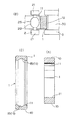
【図6】本発明の軌道輪の製造方法で使用されるサイジング型焼入れ装置の概念図。
【図7】従来の軌道輪の製造方法での各工程のヒートパターン(A、B)。
【図8】熱間ローリング加工前のリング状ブランクの寸法を基準寸法より変化させたときの拘束焼入れ後のリング状ブランクの溝径取代、外径取代の変化を示す図で、(A)はリング状ブランクの外径のみを変化させた場合を、(B)はリング状ブランクの内径のみを変化させた場合を、それぞれ示す。
【図9】熱間ローリング加工前のリング状ブランクの寸法を基準寸法より変化させたときのブランク重量と、拘束焼入れ後のリング状ブランクの総取代との相関関係を示す図。
【図10】本発明の実施例に係る拘束焼入れ後のリング状ブランクの切断面の金属組織の光学顕微鏡写真(倍率400)。(A)はピクラール腐食による焼入れ組織を、(B)はピクリン酸系腐食液(山本科学工具(株)製「AGSエッチャント」)の腐食によりオーステナイト粒界を発現させた結晶粒組織を、それぞれ示す。図中(B)のGSNo.は、オーステナイト結晶粒度番号(JIS法)を示す。
【図11】熱間ローリング加工前に球状化焼鈍を行ったリング状ブランクについて、拘束焼入れ後のリング状ブランクの切断面の金属組織の光学顕微鏡写真(倍率400)。(A)、(B)は、図10(A)、(B)と同様図。図中(B)のGSNo.は、図10と同様にオーステナイト結晶粒度番号(JIS法)を示す。
【符号の説明】
1 リング状素材
15 玉受溝
2 マンドレル
3 主ロール
6 焼入れ炉
61 油槽
7 サイジング型[0001]
BACKGROUND OF THE INVENTION
The present invention relates to a continuous manufacturing method from ring-shaped material molding to quenching of a bearing ring for a rolling bearing, particularly a ball bearing.
[0002]
[Prior art and solutions]
A ball bearing is a bearing in which a ball as a rolling element is interposed between an inner ring and an outer ring, which are race rings, so that the balls can roll. When manufacturing a ring from high carbon chrome bearing steel such as SUJ2 steel, the conventional method is to cut bar steel or round steel as a steel material and hot forging it into a ring-shaped material (ring blank), which is cooled Later, after heating again and spheroidizing annealing, cutting to the required shape and dimensions, forming the ball receiving groove on the peripheral surface and rolling the required dimensions at the same time by cold rolling, heating to the quenching temperature Then, a method of quenching was adopted.
[0003]
An example of the heat pattern of this manufacturing method is shown in FIG. 7A. In hot forging, after heating the columnar material of the cut steel bar to 1100 to 1200 ° C., both end surfaces of the columnar material are pressed. After rolling down and expanding the diameter, then punching out the center, forming into a ring-shaped material, and then allowing to cool, after heating again to the austenite region of 700-800 ° C. prior to the next cold rolling process By cooling in the furnace, spheroidizing annealing is performed, and carbides are finely precipitated in the steel to improve the cold workability of the steel.
[0004]
In cold rolling, the ring-shaped material is usually clamped between a mandrel that is inserted inside the ring-shaped material and presses the inner peripheral surface thereof, and a main roll that presses the outer peripheral surface of the ring-shaped material. The rolling method was adopted. In this method, a ball receiving groove forming protrusion is formed on the outer peripheral surface of either the mandrel or the main roll, and the mandrel and the main roll are pressed against each other while rotating the mandrel and the main roll in opposite directions. Then, the ring-shaped material is reduced in the thickness direction, and the ball receiving grooves of the ring-shaped material are formed and the rolled diameter is increased to a predetermined size and shape.
[0005]
Since the cold rolling method has a high molding dimensional accuracy of the ring-shaped material peripheral surface including the ball receiving groove, it was subsequently quenched and tempered without turning the peripheral surface and the ball receiving groove. . In this quenching method, for high carbon chromium bearing steel, a quenching method which is heated to austenite and then rapidly cooled in oil, commonly called a soaking method, has been widely used.
[0006]
In the other manufacturing method of the raceway, it is a ring-shaped material by hot forging, this is diameter-rolled to a predetermined dimension by hot rolling, and once allowed to cool, then it is reheated and subjected to spheroidizing annealing, Similarly, after turning the ball receiving groove and the like after cooling, a process of reheating and quenching was also performed.
[0007]
In this case, the hot rolling process is performed by pressing a ring-shaped material between a mandrel that is inserted into a heated ring-shaped material and presses the inner peripheral surface and a main roll that is pressed against and in contact with the outer peripheral surface. It was the method of rolling so that it might become.
For ring materials with a relatively large diameter, a mandrel and main roll, as well as a pair of axial rolls that clamp both ends of the ring material on the opposite side of the main roll, are used to control the width of the ring material. A method of performing the above has also been adopted (for example, Japanese Patent Laid-Open No. 62-176626).
[0008]
Although the heat pattern of this manufacturing method is shown in FIG. 7 (B), after the columnar material of the cut steel bar is heated to 1100 to 1200 ° C. and continuously subjected to hot rolling as a ring-shaped material by hot forging. The steel is allowed to cool to room temperature, and prior to the next turning process, it is heated again to the austenite region of 700 to 800 ° C. and then cooled in the furnace, thereby performing spheroidizing annealing and improving the cold workability of the steel. ing. In the next turning process, the inner and outer peripheral surfaces and the required ball receiving grooves are cut, and then quenched and tempered.
[0009]
The ring-shaped material formed by these methods and tempered and tempered is subjected to sizing treatment to correct roundness, and then grinding of the skin of the skin and precision polishing such as grinding and super-finishing of the ball receiving groove etc. To finish the race.
[0010]
[Problems to be solved by the invention]
In the above conventional manufacturing method, the inner and outer peripheral surfaces of the ring-shaped material and the ball receiving groove are formed by cold working such as cold rolling and turning. However, the high-carbon chromium bearing steel of the material has a high carbon content and is hard. Therefore, the material after hot forging or hot rolling has poor cold workability. Therefore, in order to improve cold workability such as machinability, it has been necessary to carry out spheroidizing annealing to precipitate carbides finely and spherically in the steel as described above.
[0011]
Therefore, as shown in FIGS. 7A and 7B, the conventional method inevitably includes a cold working step and a spheroidizing annealing step. Therefore, the conventional method is for hot forging or hot rolling. Heating and subsequent cooling are required, followed by high-temperature and long-time reheating for spheroidizing annealing, and heating for quenching is also required after cold working such as turning and cold rolling. Thermally uneconomical due to repeated heating.
[0012]
Furthermore, since the conventional method includes cold working and spheroidizing annealing for this purpose, the number of processing steps increases, and it is necessary to transport a ring-shaped material between the equipment and equipment dedicated to each process. Complicated and required waiting time adjustment between processes, resulting in a decrease in process efficiency, impossibility, and hindered adoption of a continuous production method.
[0013]
In the present invention, first, in the manufacturing process of a race ring from steel material or ring-shaped material to quenching, the process of cold working and spheroidizing annealing for this is abolished, and all the above problems are caused by hot working. This eliminates the spheroidizing annealing that requires a long time, thereby continuating the process, eliminating repeated cooling and reheating, reducing thermal energy and increasing production efficiency. It is intended to be illustrated.
[0014]
However, if the entire process from ring-shaped material forming to quenching is performed by hot working, generally the accuracy of forming the peripheral surface of the ring-shaped material and the ball receiving groove in hot working is cold rolling or cutting. It is not good compared to the case of cold processing such as processing. Here, it is important for the ring-shaped material after heat treatment to ensure at least the same dimensional accuracy as the inner and outer peripheral surfaces and ball receiving grooves formed by the conventional cutting process. It is necessary to secure a large cutting allowance, and the turning process cannot be omitted. In addition, the carbide dissolves in the matrix during the hot working process, and the carbide after the heat treatment is coarsely precipitated in a mesh shape, which may reduce the rolling fatigue life of the bearing race ring. A spheroidizing process is required separately.
[0015]
Secondly, the present invention solves the above-mentioned separate problems associated with hot working, and in terms of quality required for the bearing ring, it is at least inferior to that of the conventional manufacturing method. A manufacturing method is to be provided.
[0016]
[Means for Solving the Problems]
The present invention relates to a method of manufacturing a bearing ring for ball bearings for forming a bearing ring for ball bearings from a ring-shaped material made of high carbon chromium bearing steel that can be hardened by cooling in oil. It is formed into a grooved ring-shaped material having a dimensional accuracy that does not require subsequent cutting by intermediate rolling and constrained quenching.
That is, in the manufacturing method of the present invention, a ring-shaped material is heated to a processing start temperature of 750 to 900 ° C., a ball receiving groove is formed by hot rolling, the diameter is expanded to a predetermined outer shape, and rolled into a grooved ring-shaped material. A hot rolling process for forming, and a quenching process in which the grooved ring-shaped material is reheated to the quenching temperature immediately after the rolling process and then quenched, and the quenching method in the quenching process is performed outside the heated ring-shaped material. It is a constrained quenching in which the diameter or the inner diameter is constrained and held in a state of being constrained to a predetermined dimension, Perform at 850-860 ° C. for 2-3 minutes It is characterized by that.
[0017]
The process of this manufacturing method is shown in FIG. 1 (A). In this method, in the hot rolling process of the ring-shaped material, the ring-shaped material has a predetermined ball receiving groove and a peripheral surface / side surface. A ring-shaped material having a predetermined shape, which is formed at a high temperature and at a time, and is subjected to the following constrained quenching process and is integrally quenched. The hot rolling process b is extremely easy to form a ball-receiving groove and to expand the diameter of the roll, and does not employ cold working such as conventional grooving or cold rolling, so spheroidizing annealing for the cold working described above. This step becomes unnecessary.
Therefore, as shown in FIG. 2A, an example of the heat pattern, there is no need to cool to room temperature between the hot rolling process and the quenching process, and even if there is a temperature drop in the hot rolling process. Yes, it can be quenched immediately after a short heating adjustment to the quenching temperature. Therefore, continuous production of the hot rolling process and the quenching process is facilitated, and the entire process is completed in a short time, which is effective in reducing the time required for heating and thermal energy.
[0018]
Rolling of a ring-shaped material by hot rolling processing is inferior in dimensional accuracy compared to the case of conventional cold rolling processing, and in particular, the roundness may be reduced. Quenching is completed while the outer diameter or inner diameter of the ring-shaped material after rolling is constrained and held at a specified size, and this corrects or prevents both dimensional variations during hot rolling and deformation distortion during quenching. There is an effect to. Therefore, a ring-shaped material having high dimensional accuracy and roundness that leaves the required grinding allowance can be obtained, and thereafter it can be advanced to final finishing without cutting.
[0019]
For constrained quenching, in the process diagram of FIG. 1 (A) and the heat pattern illustrated in FIG. 2 (A), a ring-shaped material that has been heated and held at the austenitizing temperature by reheating d immediately after rolling b is quenched. There is a method of performing a sizing quenching f in which the steel is immersed in oil, rapidly cooled, elevated to a temperature just above the martensite transformation start temperature Ms of the steel, and then pressed into a sizing mold and cooled. The martensitic transformation is completed in the process of cooling the ring-shaped material to near room temperature while constrained by a sizing die. After this quenching, this is subjected to normal tempering so that the surface hardness is HRC57 or higher, particularly HRC60 or higher, and the wear resistance and rolling fatigue life of the raceway groove are ensured.
[0020]
The present invention includes a method for manufacturing a bearing ring in which a spheroidizing process is interposed between the hot rolling process and the constrained quenching process.
That is, in this manufacturing method, the process diagram is shown in FIG. 1 (B) and the example of the heat pattern is shown in FIG. 2 (B). The ring material is heated at least in the austenite region and heated. A hot rolling process in which a ball receiving groove is formed by the intermediate rolling process b, the diameter is expanded to a predetermined outer shape and rolled into a grooved ring-shaped material, and the ring-shaped material is immediately below the Ar1 point of the steel immediately after the rolling process is completed. After maintaining the temperature of 500 ° C. or higher and performing a spheroidizing treatment c for precipitating spherical carbides in the steel, and immediately adjusting the quenching temperature by reheating the ring-shaped material after the spheroidizing treatment. And a quenching step of quenching. The quenching method is similarly a constrained quenching method in which the outer diameter or inner diameter of the ring-shaped material that has been reheated d is cooled while being constrained and held at a predetermined size. As described above, the constrained quenching method includes a sizing type quenching method in which the steel is dipped in oil after being reheated d, rapidly cooled e, raised at a temperature just above the Ms point of the steel, and then subjected to sizing (type) quenching f.
[0021]
In the method including the spheroidization treatment c, at least the initial stage of the hot rolling process b is performed in the austenite region, and after the completion, the carbon dissolved in the austenite is kept at a temperature not higher than the Ar1 point of the steel and not lower than 500 ° C. Precipitate as fine spherical carbides. This is effective in preventing a decrease in rolling fatigue life due to coarse carbides such as reticulated cementite due to hot working.
[0022]
The manufacturing method including the spheroidizing treatment is performed in order to form a ring-shaped material in advance for a steel containing a large amount of precipitated carbides in the steel, such as a high carbon steel, particularly a high carbon chromium bearing steel (for example, SUJ2 steel). It is preferably applied when hot forging is performed or when hot rolling is performed from a high temperature of around 1000 ° C.
In the process of hot forging and hot rolling, if austenite is at a high temperature of about 1000 ° C., carbides dissolve well in austenite, and after that, precipitates as coarse carbides in a network form at the austenite grain boundaries during cooling. However, in the present invention, the spheroidizing process is provided to refine the carbide.
[0023]
DETAILED DESCRIPTION OF THE INVENTION
To describe the present invention in more detail, the steel material used has a ring cross section rectangular shape as shown in FIG. 4 (A) by hot forging after cutting a steel bar or round steel (billet) into a certain length. It is formed in a ring shape. In general, a so-called parent-child method is employed in which two ring-shaped materials for an inner ring and an outer ring are formed from a single steel bar piece. A ring-shaped material obtained by cutting a steel pipe into a certain length is also used.
The ring-shaped material is heated for hot rolling after the inner peripheral surface, outer peripheral surface and both end surfaces are adjusted to a certain size range by turning.
[0024]
In the present invention, in the hot rolling process, the ring-shaped material is charged into a heating furnace and heated and held near the rolling process starting temperature. The rolling process starting temperature is an austenite region of 1200 ° C. or lower, preferably, A low temperature range of 750 ° C to 900 ° C is selected. When the temperature is higher than 900 ° C., the steel material of the ring-shaped material has a low deformation resistance and is soft and can be easily rolled. However, the surface decarburized layer tends to increase due to surface oxidation during heating and rolling. Heating at a high temperature is disadvantageous in terms of thermoeconomics.
[0025]
On the other hand, if the rolling processing start temperature is lower than 750 ° C., the steel of the ring-shaped material becomes hard without spheroidizing annealing, which is disadvantageous for rolling processing and rolling diameter expansion. In addition, when performing spheroidizing annealing after hot rolling, it is necessary to set the rolling processing end temperature to 500 ° C. or higher, particularly 650 ° C. or higher, so that temperature drop in the hot rolling process is taken into consideration. The rolling processing start temperature is determined.
As the heating furnace, a gas furnace or an electric furnace is used. In particular, an atmosphere furnace substituted with nitrogen gas or reducing gas is preferable for preventing air oxidation and decarburization on the surface of the ring-shaped material.
[0026]
As a method of hot rolling, a method of rolling by pressing a ring-shaped material between a mandrel and a main roll used in the above-described cold rolling method can be adopted. A ball receiving groove forming protrusion is formed on either outer peripheral surface of the mandrel and the main roll to form a groove forming roll, pressing between the mandrel and the main roll while rotating the mandrel and the main roll, By the reduction in the thickness direction of the ring-shaped material and the rotation of the ring-shaped material, the ring-shaped material is formed with a groove and rolled to a predetermined size.
[0027]
Since the ring-shaped material is cooled in the hot rolling process, in the quenching process, it is charged in a quenching furnace and reheated to adjust the quenching temperature, usually 800 ° C to 860 ° C austenitizing temperature. . The rolling start temperature may be determined so that the rolling end temperature is in the vicinity of the quenching temperature in consideration of the temperature drop in the hot rolling process. Then, reheating before quenching can be omitted, and quenching can be performed immediately after the end of rolling.
[0028]
When a spheroidizing treatment step is provided after the hot rolling step, the rolling processing start temperature is set to an austenite region of 750 ° C. or higher, but it is preferable to increase the temperature to 800 ° C. or higher in order to increase the solubility of carbides. . At least the initial stage of the hot rolling process is performed in the austenite region, and the spheroidizing process c is performed after quenching by holding the steel at a temperature not lower than the Ar1 point of the steel at 500 ° C. or higher, particularly about 650 ° C. This is performed in the process of reheating d.
[0029]
The spheroidizing treatment c is a method in which the temperature at the end of the hot rolling process b is adjusted to a temperature not higher than the Ar1 point and not lower than 500 ° C., and there is a method of reheating d to the austenitizing temperature gradually immediately after the end of the rolling process b. As another method, a ring-shaped material that has been subjected to hot rolling b is temporarily immersed in a salt bath at a temperature not higher than Ar1 and not lower than 500 ° C., and then charged into a heating furnace for quenching, and gradually austenite A method of reheating d up to the crystallization temperature is also employed.
[0030]
In the next constraining quenching process, an outer diameter constraining type and an inner diameter constraining type are used as the sizing type, but in the case of the outer diameter constraining type, rapid cooling e is performed from the reheated austenite region to just above the Ms point. Then, while maintaining this temperature, a ring-shaped material is press-fitted into an internal cylindrical sizing mold having a predetermined inner diameter. In the press-fitting process, the outer diameter of the ring-shaped material is compressed to be constrained to the inner diameter of the sizing type inner surface, and after press-fitting, this is allowed to cool below the Ms point to cause martensitic transformation and sizing quenching f. Method (use of marquenching method). The inner surface of the sizing die is determined to have a predetermined cylindrical shape, and the quenching is completed in a state where the outer peripheral surface of the ring-shaped material is corrected and restrained in the sizing die.
[0031]
In this process, when the ring-shaped materials pulled up sequentially from the quenching oil tank are sequentially pressed into the sizing mold from the inlet side in a stacked state, they are pushed in while being cooled in the mold and quenched from the outlet side. A method in which a ring-shaped material comes out is good.
[0032]
In the case of the inner diameter restraint type, the inner diameter of the ring-shaped material is expanded to the outer diameter of the sizing mold outer surface by constraining the inner diameter of the ring-shaped material successively into a cylindrical sizing mold having a predetermined outer diameter. Thereafter, as in the case of the above-described outer diameter constrained type, this is a method in which the martensite transformation is performed by cooling below the Ms point.
[0033]
The ring-shaped material formed and quenched by the method of the present invention is tempered at 150 to 200 ° C. in the same manner as the conventional method, and then the ring-shaped material is ground and polished by superfinishing the outer surface of the black skin and the ball receiving groove. Is done. In the manufacturing method of the present invention, the dimension of the ring-shaped material after quenching can be sufficiently ensured with sufficient accuracy to leave a grinding allowance even if cutting is omitted in the finishing process.
Furthermore, the manufacturing method of the present invention can make the hot rolling processing start temperature in a low temperature range of 750 ° C. to 900 ° C., and can perform constrained quenching just by reheating immediately after the rolling processing. The growth and coarsening of the austenite crystal grains broken by the processing are suppressed, so that the austenite crystal grains immediately before quenching can be made fine, and there is an advantage that the mechanical properties of the raceway are improved.
[0034]
【Example】
A method for manufacturing a ring-shaped material used for the inner ring raceway of the deep groove ball bearing from the SUJ2 steel bar will be described below in accordance with the process diagram of FIG.
A steel bar is cut into a predetermined length, inserted into a heating furnace and heated to around 1100 ° C., then formed into a ring shape by hot forging, and after cooling, it is prepared into a predetermined shape by turning, and a ring-shaped material It is said.
First, the ring-shaped material is heated and held in a range of 800 ° C. to 860 ° C. for 30 to 60 minutes while being sequentially charged into a heating furnace and transferred through the furnace for hot rolling.
[0035]
In the hot rolling process, a mandrel is inserted into the ring-shaped material taken out from the heating furnace, the outer periphery of the ring is clamped by the main roll, the ring is pressed down in the thickness direction, and the diameter is expanded. A ball receiving groove forming protrusion is formed on the outer periphery of the main roll, and the ball receiving groove is formed on the inner peripheral surface of the ring-shaped material. An outline of this rolling processing apparatus is shown in FIG. 3. A
[0036]
When the inner ring of the raceway ring is formed by this method, the ball
[0037]
As illustrated in FIG. 6, the constrained quenching apparatus is provided with a cooling
[0038]
In order to carry out this series of steps, a heating furnace for hot rolling, a hot rolling device, a heating furnace for quenching, and a constrained quenching device consisting of an oil bath, a sizing mold and a pushing device are continuously processed. Although not shown, between the heating furnace and the cold rolling device or the constraining quenching device, the ring-shaped material is conveyed one by one quickly by gripping conveying means such as a robot arm. Have been able to.
[0039]
Since hot rolling can normally complete rolling in 10 seconds or less, it is possible to transfer and install from a rolling heating furnace to a hot rolling device, or to remove and insert from a hot rolling device to a quenching heating furnace. It is performed rapidly, and the cooling in the air during that period is reduced to prevent a temperature drop.
[0040]
In this hot rolling method, the ball receiving groove and the seal groove are simultaneously formed in the ring-shaped material by providing the seal groove forming protrusion together with the ball receiving groove forming protrusion formed on the main roll or the mandrel. Is possible. In FIG. 5 (A), an example in which a ball receiving
[0041]
In the conventional cold rolling method, when forming the inner ring of the bearing ring, if the ball receiving groove and the seal groove are simultaneously formed on the outer peripheral surface of the inner ring, due to the tensile stress acting on the peripheral surface of the material during rolling diameter expansion. Although minute surface cracks may occur on the circumferential surface between both grooves, hot rolling does not cause surface cracks due to the large plastic deformability of the steel itself, and the same applies to both inner and outer rings. There is an advantage that the simultaneous formation of the seal groove can be facilitated.
[0042]
Next, the dimensional accuracy and microstructure when the bearing ring is formed by the method for manufacturing a bearing ring for ball bearing of the present invention are examined, and the results are shown below.
The bearing ring is an outer ring of a ball bearing of JIS model number 6206, and the material is SUJ2 steel.
The manufacturing conditions were as follows. A steel bar made of the above material was formed into a ring-shaped blank by hot forging, and this was turned to adjust the dimensions to a ring-shaped blank for hot rolling. The reference dimensions of the ring-shaped blank are an inner diameter of 36.5 mm, an outer diameter of 48.1 mm, and a width of 16.0 mm. A ring-shaped blank changed to 0.10 mm was formed.
These ring-shaped blanks are heated in a heating furnace to a furnace temperature of 850 to 860 ° C. for 20 to 30 minutes, immediately subjected to hot rolling with the above rolling machine to perform ball receiving groove forming and rolling, and a heating furnace for quenching Then, after reheating for 2 to 3 minutes at a furnace temperature of 850 to 860 ° C., dipped in oil with an oil temperature of 100 to 110 ° C. for 10 s, pulled up and pressed into a sizing mold with an inner diameter of 62.15 mm and a length of 80 mm Then, it was allowed to cool and subjected to restraint quenching. In this test, the ring-shaped blank after hot rolling is immediately reheated to the quenching temperature without performing spheroidization.
Further, as a comparative example, spheroidizing annealing was performed in advance under the condition that the ring-shaped blank was held at a furnace temperature of 800 ° C. for 9 to 10 hours and gradually cooled before turning after hot forging. Other manufacturing conditions were the same as above.
[0043]
For the constrained and quenched ring-shaped blank, the outer diameter and inner diameter (groove diameter) of the ball receiving groove surface are measured as the inner diameter, and compared with the outer diameter and groove diameter of the outer ring of the product. I asked for the allowance. FIG. 8 shows the relationship between each machining allowance and the dimensions of the ring-shaped blank before rolling. When the ring-shaped blank before rolling is at the standard dimension, both the outer diameter allowance and the groove diameter allowance are in the range of 0.1 to 0.2 mm, both of which are appropriate grinding allowances. In A), when only the outer diameter of the ring-shaped blank is −0.05 mm or less with respect to the reference outer diameter, the groove diameter allowance is 0.1 mm or less. On the other hand, in FIG. 8B, when only the inner diameter of the ring-shaped blank is +0.10 mm with respect to the reference inner diameter, the outer diameter allowance is 0.1 mm or less, particularly 0 mm or less, and the allowance cannot be secured. In any case, if an appropriate reference dimension is determined, the outer diameter and inner diameter of the ring blank are controlled within a certain range, and the inner surface shape of the sizing type is set so as to secure the outer diameter allowance, the present invention. The outer ring machining allowance and the groove bore machining allowance can be appropriately secured by the method of manufacturing the raceway by hot working, and it has been found that the method of the present invention has sufficiently high machining accuracy of the raceway.
[0044]
Fig. 9 shows the relationship between the sum of the outer diameter allowance and the groove diameter allowance (total allowance) and the ring blank weight before rolling. The ring blank is a blank with only the outer diameter changed. However, there is a close correlation between the blank weight and the total machining allowance, and the weight tolerance for securing the total machining allowance is determined using this.
[0045]
The microstructure of the ring-shaped blank after constrained quenching is sufficient for the carbide as shown in the micrograph of FIG. 10 (A) even if both the conventional spheroidizing annealing and the spheroidizing treatment after hot rolling are omitted. It turned out to be spheroidized. As a comparative example, after performing spheroidizing annealing after hot forging, compared with the microstructure after constrained quenching of a blank that was subjected to the same manufacturing method as in the example (a micrograph is shown in FIG. 11A). However, the carbide is fine and the amount of precipitation of the carbide is large.
[0046]
The austenite crystal grains of the ring-shaped blank after constrained quenching are extremely fine with the austenite
[0047]
As described above, the production method of the present invention has features such that the spheroidization of carbides can be realized without providing a special spheroidizing treatment in terms of quality, and it is effective for the refinement of crystal grains. ing.
[Brief description of the drawings]
FIG. 1 is a process diagram (A, B) of a method for manufacturing a bearing ring of the present invention.
FIG. 2 is a heat pattern (A, B) in the manufacturing process of the method for manufacturing a raceway according to the present invention.
FIGS. 3A and 3B are hot rolling processing apparatuses used in the method of manufacturing a bearing ring according to the present invention, in which FIG. 3A is a top view of the apparatus before starting the rolling process, and FIG. 3B is a top view of the apparatus during the rolling process. FIG. 4C is a longitudinal sectional view of the apparatus in a state during rolling.
FIG. 4 is a cross-sectional view (A) of a ring-shaped material for an outer ring before processing in the hot rolling process used in the method for manufacturing a bearing ring according to the present invention, and shows a ring-shaped material, a mandrel, and a main roll. The figure (B) which shows arrangement | positioning, and sectional drawing (C) of the ring-shaped raw material for outer rings after a process are each shown.
FIG. 5A is a view showing the arrangement of a ring-shaped material, a mandrel, and a main roll in the hot rolling process used in the method for manufacturing a bearing ring according to the present invention; Sectional drawing (B) of a ring-shaped raw material is shown, respectively.
FIG. 6 is a conceptual diagram of a sizing type quenching device used in the method for manufacturing a raceway according to the present invention.
FIG. 7 is a heat pattern (A, B) of each process in the conventional method for manufacturing a raceway ring.
FIG. 8 is a view showing changes in the groove allowance and outer diameter allowance of the ring-shaped blank after restraint quenching when the dimension of the ring-shaped blank before hot rolling is changed from the reference dimension; (B) shows the case where only the inner diameter of the ring blank is changed, and (B) shows the case where only the outer diameter of the ring blank is changed.
FIG. 9 is a diagram showing the correlation between the blank weight when the dimension of the ring-shaped blank before hot rolling is changed from the reference dimension and the total machining allowance of the ring-shaped blank after constrained quenching.
FIG. 10 is an optical micrograph (magnification 400) of a metal structure of a cut surface of a ring-shaped blank after constrained quenching according to an example of the present invention. (A) shows a quenching structure by picral corrosion, and (B) shows a crystal grain structure in which austenite grain boundaries are expressed by corrosion of a picric acid-based corrosion liquid (“AGS etchant” manufactured by Yamamoto Kagaku Tool Co., Ltd.). . In the figure, GSNo. Indicates an austenite grain size number (JIS method).
FIG. 11 is an optical micrograph (magnification 400) of the metal structure of the cut surface of the ring-shaped blank after constrained quenching for a ring-shaped blank that has been spheroidized before hot rolling. (A), (B) is a figure similar to FIG. 10 (A), (B). In the figure, GSNo. Indicates the austenite grain size number (JIS method) as in FIG.
[Explanation of symbols]
1 Ring material
15 Ball receiving groove
2 Mandrels
3 Main roll
6 Quenching furnace
61 Oil tank
7 Sizing type
Claims (7)
該リング状素材を加工開始温度750〜900℃に加熱して熱間ローリング加工により玉受溝を形成して所定外形に拡径する熱間ローリング工程と、
上記ローリング加工後該リング状素材を直ちに焼入れ温度に再加熱した後焼入れする焼入れ工程と、から成り、
上記焼入れ工程における焼入れ法が、加熱したリング状素材の外径若しくは内径を所定寸法に拘束保持した状態で冷却する拘束焼入れであり、
上記焼入れ工程における再加熱を、850〜860℃で2〜3分行うことを特徴とする玉軸受用軌道輪の製造方法。In a method for manufacturing a ball bearing ring for forming a ball bearing ring from a ring-shaped material made of high carbon chromium bearing steel that can be hardened by cooling in oil,
A hot rolling process in which the ring-shaped material is heated to a processing start temperature of 750 to 900 ° C. and a ball receiving groove is formed by hot rolling to expand the diameter to a predetermined outer shape;
A quenching process in which the ring-shaped material is immediately reheated to a quenching temperature after the rolling process and then quenched.
The quenching method in the quenching step is restraint quenching in which the outer diameter or inner diameter of the heated ring-shaped material is cooled while being restrained and held at a predetermined dimension,
Reheating in the said hardening process is performed at 850-860 degreeC for 2 to 3 minutes , The manufacturing method of the bearing ring for ball bearings characterized by the above-mentioned.
該球状化処理後のリング状素材を直ちに上記焼入れ温度に加熱調整するようにしたことを特徴とする請求項1又は2記載の軸受軌道輪の製造方法。Between the hot rolling step and the quenching step, the ring-shaped material after the rolling process is immediately held at a temperature not higher than the Ar1 point of steel and not lower than 500 ° C. to precipitate spherical carbides in the steel. Including steps,
3. The method for manufacturing a bearing race according to claim 1, wherein the spheroidized ring-shaped material is immediately heated to the quenching temperature.
Priority Applications (1)
| Application Number | Priority Date | Filing Date | Title |
|---|---|---|---|
| JP35175995A JP3965525B2 (en) | 1995-12-26 | 1995-12-26 | Method of manufacturing bearing ring for ball bearing |
Applications Claiming Priority (1)
| Application Number | Priority Date | Filing Date | Title |
|---|---|---|---|
| JP35175995A JP3965525B2 (en) | 1995-12-26 | 1995-12-26 | Method of manufacturing bearing ring for ball bearing |
Publications (2)
| Publication Number | Publication Date |
|---|---|
| JPH09176740A JPH09176740A (en) | 1997-07-08 |
| JP3965525B2 true JP3965525B2 (en) | 2007-08-29 |
Family
ID=18419420
Family Applications (1)
| Application Number | Title | Priority Date | Filing Date |
|---|---|---|---|
| JP35175995A Expired - Fee Related JP3965525B2 (en) | 1995-12-26 | 1995-12-26 | Method of manufacturing bearing ring for ball bearing |
Country Status (1)
| Country | Link |
|---|---|
| JP (1) | JP3965525B2 (en) |
Cited By (1)
| Publication number | Priority date | Publication date | Assignee | Title |
|---|---|---|---|---|
| CN102441768A (en) * | 2010-11-15 | 2012-05-09 | 江苏万达特种轴承有限公司 | Processing technology of bearing steel double-hardness roller ring |
Families Citing this family (30)
| Publication number | Priority date | Publication date | Assignee | Title |
|---|---|---|---|---|
| US7438477B2 (en) | 2001-11-29 | 2008-10-21 | Ntn Corporation | Bearing part, heat treatment method thereof, and rolling bearing |
| ES2259176T3 (en) | 2002-10-17 | 2006-09-16 | Ntn Corporation | ROLLER CAM FOLLOWER FOR AN ENGINE. |
| US7334943B2 (en) | 2003-02-28 | 2008-02-26 | Ntn Corporation | Differential support structure, differential's component, method of manufacturing differential support structure, and method of manufacturing differential's component |
| JP4362394B2 (en) | 2003-03-28 | 2009-11-11 | Ntn株式会社 | Compressor bearing |
| EP1707831B1 (en) | 2004-01-09 | 2012-02-01 | NTN Corporation | Thrust needle roller bearing, support structure receiving thrust load of compressor for car air-conditioner, support structure receiving thrust load of automatic transmission, support structure for nonstep variable speed gear, and support structure receiving thrust load of manual transmission |
| JP4540351B2 (en) | 2004-01-15 | 2010-09-08 | Ntn株式会社 | Steel heat treatment method and bearing part manufacturing method |
| JP2006194306A (en) * | 2005-01-12 | 2006-07-27 | Nsk Ltd | Manufacturing method of clutch release bearing |
| JP5036165B2 (en) * | 2005-11-09 | 2012-09-26 | Ntn株式会社 | Mold quenching method and restraint type device for ring-shaped product |
| JP5121168B2 (en) | 2006-06-01 | 2013-01-16 | Ntn株式会社 | Rolling member manufacturing method and rolling bearing manufacturing method |
| US8177928B2 (en) | 2006-09-20 | 2012-05-15 | Ntn Corporation | Method of restrained-quenching of annular member |
| JP5151489B2 (en) | 2007-01-16 | 2013-02-27 | 日本精工株式会社 | Manufacturing method of bearing outer ring |
| CN101809174B (en) | 2007-09-28 | 2012-04-11 | Ntn株式会社 | Quenching method and device of ring-shaped article |
| JP2009197899A (en) * | 2008-02-21 | 2009-09-03 | Ntn Corp | Double-row angular bearing |
| CN101903667A (en) * | 2007-12-17 | 2010-12-01 | Ntn株式会社 | Double row angular bearing, bearing device for wheel, method for manufacturing outer ring, and method for manufacturing inner ring |
| JP2009144859A (en) * | 2007-12-17 | 2009-07-02 | Ntn Corp | Bearing device for wheel and method for manufacturing outer ring |
| JP5998438B2 (en) * | 2011-07-25 | 2016-09-28 | 日本精工株式会社 | Restraint quenching method and restraint quenching apparatus |
| ITTO20120266A1 (en) * | 2012-03-26 | 2013-09-27 | Skf Ab | METHOD FOR THE REALIZATION OF A STEEL INSERT FOR AN EXTERNAL RING OF A ROLLING BEARING, IN PARTICULAR OF A WHEEL HUB UNIT |
| ITTO20120267A1 (en) * | 2012-03-26 | 2013-09-27 | Skf Ab | EQUIPMENT FOR THE REALIZATION OF ROLLEDURING A COMPULSORY ANULAR ELEMENT, IN PARTICULAR A STEEL INSERT FOR AN EXTERNAL RING OF A ROLLING BEARING |
| JP6263945B2 (en) * | 2013-10-11 | 2018-01-24 | 株式会社ジェイテクト | Bearing assembly method |
| CN103725837A (en) * | 2014-01-23 | 2014-04-16 | 唐山亚捷机械有限公司 | Die quenching process and equipment for free cooling in oil and martensitic transformation on machine tool |
| JP6326933B2 (en) * | 2014-04-21 | 2018-05-23 | 大同特殊鋼株式会社 | Ring manufacturing method |
| EP3167970B1 (en) | 2014-07-10 | 2019-02-20 | NTN Corporation | Method of manufacturing a rolling bearing ring and rolling bearing ring |
| JP6423740B2 (en) * | 2015-02-20 | 2018-11-14 | Ntn株式会社 | Manufacturing method of bearing ring |
| CN105154653A (en) * | 2015-07-27 | 2015-12-16 | 南通昊友食品添加剂有限公司 | Heat treatment method for bearing ring special for food additive drying device |
| CN106834653B (en) * | 2017-02-23 | 2018-03-16 | 武汉理工大学 | A kind of bearing ring forging tissue fast spheroidizing annealing method based on controll cooling after forging |
| CN107262642A (en) * | 2017-06-21 | 2017-10-20 | 安徽金越轴承有限公司 | Process for stabilizing is forged in a kind of bearing holder (housing, cover) hot extrusion |
| CN109909437A (en) * | 2019-05-05 | 2019-06-21 | 临清市同兴轴承锻造有限公司 | A kind of bearing ring forging processing technology and processing system |
| CN112032193B (en) * | 2020-09-29 | 2024-03-08 | 江苏万达特种轴承股份有限公司 | Precision three-ring composite bearing and manufacturing method thereof |
| CN115608891B (en) * | 2022-09-30 | 2023-07-11 | 中南大学 | A manufacturing method and device for a special-shaped cross-section transition ring of a rocket tank |
| CN119710534A (en) * | 2024-12-20 | 2025-03-28 | 武汉理工大学 | Gradient Ma Bei multiphase structure construction forming manufacturing method for high-carbon steel bearing under extreme working condition |
-
1995
- 1995-12-26 JP JP35175995A patent/JP3965525B2/en not_active Expired - Fee Related
Cited By (1)
| Publication number | Priority date | Publication date | Assignee | Title |
|---|---|---|---|---|
| CN102441768A (en) * | 2010-11-15 | 2012-05-09 | 江苏万达特种轴承有限公司 | Processing technology of bearing steel double-hardness roller ring |
Also Published As
| Publication number | Publication date |
|---|---|
| JPH09176740A (en) | 1997-07-08 |
Similar Documents
| Publication | Publication Date | Title |
|---|---|---|
| JP3965525B2 (en) | Method of manufacturing bearing ring for ball bearing | |
| CN101460754B (en) | Process for manufacturing rolling member, process for manufacturing rolling bearing, raceway member of rolling bearing and rolling bearing | |
| US3927450A (en) | Method of manufacturing hollow, circular-shaped workpieces | |
| WO1999034023A1 (en) | Continuous annealing furnace, rolling bearing, annealing method, and method of manufacturing inner and outer races of deeply groove ball bearing | |
| JPH11140543A (en) | Manufacturing method of bearing race | |
| CN1863931B (en) | Manufacturing method of thin-walled parts, bearing ring, thrust needle roller bearing, manufacturing method of rolling bearing bearing ring, rolling bearing bearing ring and rolling bearing | |
| WO2005075121A1 (en) | Cold-finished seamless steel pipe | |
| JP4627981B2 (en) | Manufacturing method of thin bearing race | |
| JP2003194072A (en) | Rolling device | |
| WO2005033346A1 (en) | Thin-walled part producing method, bearing raceway ring, thrust needle roller bearing, rolling bearing raceway ring producing method, rolling bearing raceway ring, and rolling bearing | |
| JP2006328465A (en) | Manufacturing method of bearing ring for rolling bearing, bearing ring for rolling bearing, rolling bearing | |
| JP2009203521A (en) | Heat deformation straightening method of annular body, and its hardening method | |
| JP2000001723A (en) | Bearing material for cold rolling forming and its forming member | |
| JP4712603B2 (en) | Rolling part manufacturing method, race ring and bearing | |
| JPH11347673A (en) | Rolling bearing and method of manufacturing the same | |
| CN112981083A (en) | Heat treatment method of full-hardened withdrawal and straightening roller | |
| CN115927830B (en) | Heat treatment method for large size bearing rings | |
| JP2006089795A (en) | Rolling bearing race ring and its producing method, and rolling bearing | |
| JP2524156B2 (en) | High carbon steel tough parts manufacturing method | |
| JPS5836649B2 (en) | Method for manufacturing hot rolling mill work rolls | |
| CN101733642A (en) | Process for machining L-shaped ferrule of rotary bearing | |
| JP2010007798A (en) | Rolling bearing unit for supporting wheel and its manufacturing method | |
| JPS60167724A (en) | Method of manufacturing outer cylinder of equal-speed joint | |
| CN110760664A (en) | A repair heat treatment process for improving the performance of a blooming graphite steel roll | |
| JP2006219725A (en) | Manufacturing method of bearing race |
Legal Events
| Date | Code | Title | Description |
|---|---|---|---|
| A977 | Report on retrieval |
Free format text: JAPANESE INTERMEDIATE CODE: A971007 Effective date: 20050324 |
|
| A131 | Notification of reasons for refusal |
Free format text: JAPANESE INTERMEDIATE CODE: A131 Effective date: 20060516 |
|
| A521 | Written amendment |
Free format text: JAPANESE INTERMEDIATE CODE: A523 Effective date: 20060718 |
|
| A131 | Notification of reasons for refusal |
Free format text: JAPANESE INTERMEDIATE CODE: A131 Effective date: 20061031 |
|
| A521 | Written amendment |
Free format text: JAPANESE INTERMEDIATE CODE: A523 Effective date: 20061220 |
|
| A131 | Notification of reasons for refusal |
Free format text: JAPANESE INTERMEDIATE CODE: A131 Effective date: 20070130 |
|
| A521 | Written amendment |
Free format text: JAPANESE INTERMEDIATE CODE: A523 Effective date: 20070322 |
|
| TRDD | Decision of grant or rejection written | ||
| A01 | Written decision to grant a patent or to grant a registration (utility model) |
Free format text: JAPANESE INTERMEDIATE CODE: A01 Effective date: 20070417 |
|
| A61 | First payment of annual fees (during grant procedure) |
Free format text: JAPANESE INTERMEDIATE CODE: A61 Effective date: 20070515 |
|
| R150 | Certificate of patent or registration of utility model |
Free format text: JAPANESE INTERMEDIATE CODE: R150 |
|
| FPAY | Renewal fee payment (event date is renewal date of database) |
Free format text: PAYMENT UNTIL: 20100608 Year of fee payment: 3 |
|
| FPAY | Renewal fee payment (event date is renewal date of database) |
Free format text: PAYMENT UNTIL: 20110608 Year of fee payment: 4 |
|
| FPAY | Renewal fee payment (event date is renewal date of database) |
Free format text: PAYMENT UNTIL: 20110608 Year of fee payment: 4 |
|
| FPAY | Renewal fee payment (event date is renewal date of database) |
Free format text: PAYMENT UNTIL: 20120608 Year of fee payment: 5 |
|
| FPAY | Renewal fee payment (event date is renewal date of database) |
Free format text: PAYMENT UNTIL: 20120608 Year of fee payment: 5 |
|
| FPAY | Renewal fee payment (event date is renewal date of database) |
Free format text: PAYMENT UNTIL: 20130608 Year of fee payment: 6 |
|
| R250 | Receipt of annual fees |
Free format text: JAPANESE INTERMEDIATE CODE: R250 |
|
| R250 | Receipt of annual fees |
Free format text: JAPANESE INTERMEDIATE CODE: R250 |
|
| LAPS | Cancellation because of no payment of annual fees |