JP2010007798A - Rolling bearing unit for supporting wheel and its manufacturing method - Google Patents
Rolling bearing unit for supporting wheel and its manufacturing method Download PDFInfo
- Publication number
- JP2010007798A JP2010007798A JP2008169567A JP2008169567A JP2010007798A JP 2010007798 A JP2010007798 A JP 2010007798A JP 2008169567 A JP2008169567 A JP 2008169567A JP 2008169567 A JP2008169567 A JP 2008169567A JP 2010007798 A JP2010007798 A JP 2010007798A
- Authority
- JP
- Japan
- Prior art keywords
- hot forging
- wheel
- inner member
- rolling bearing
- bearing unit
- Prior art date
- Legal status (The legal status is an assumption and is not a legal conclusion. Google has not performed a legal analysis and makes no representation as to the accuracy of the status listed.)
- Granted
Links
Images
Classifications
-
- F—MECHANICAL ENGINEERING; LIGHTING; HEATING; WEAPONS; BLASTING
- F16—ENGINEERING ELEMENTS AND UNITS; GENERAL MEASURES FOR PRODUCING AND MAINTAINING EFFECTIVE FUNCTIONING OF MACHINES OR INSTALLATIONS; THERMAL INSULATION IN GENERAL
- F16C—SHAFTS; FLEXIBLE SHAFTS; ELEMENTS OR CRANKSHAFT MECHANISMS; ROTARY BODIES OTHER THAN GEARING ELEMENTS; BEARINGS
- F16C2326/00—Articles relating to transporting
- F16C2326/01—Parts of vehicles in general
- F16C2326/02—Wheel hubs or castors
Abstract
Description
本発明は、自動車等の車輪を懸架装置に対して回転自在に支持する車輪支持用転がり軸受ユニット及びその製造方法に関する。 The present invention relates to a wheel-supporting rolling bearing unit that rotatably supports a wheel of an automobile or the like with respect to a suspension device and a method for manufacturing the same.
自動車等の車輪を懸架装置に対して回転自在に支持する車輪支持用転がり軸受ユニットは、一般的には、以下のような構造を有している。すなわち、外周面に複列の軌道面を有する内方部材と、内周面に複列の軌道面を有する外方部材と、内方部材の軌道面と外方部材の軌道面との間に転動自在に配された複数の転動体と、を備えており、内方部材が回転輪、外方部材が固定輪(非回転輪)とされている。 A wheel bearing rolling bearing unit that rotatably supports a wheel of an automobile or the like with respect to a suspension device generally has the following structure. That is, an inner member having a double-row raceway surface on the outer peripheral surface, an outer member having a double-row raceway surface on the inner peripheral surface, and between the raceway surface of the inner member and the raceway surface of the outer member A plurality of rolling elements which are arranged to be freely rollable, the inner member being a rotating wheel and the outer member being a fixed wheel (non-rotating wheel).
また、内方部材の外周面には、車輪を取り付けるためのフランジが設けられ、外方部材の外周面には、懸架装置を取り付けるためのフランジが設けられている。そして、このような車輪支持用転がり軸受ユニットは、前述のフランジが内方部材や外方部材に一体化された構造となっている。
車輪支持用転がり軸受ユニットを構成する内方部材,外方部材は、例えばS53Cのような機械構造用炭素鋼の中炭素鋼を材料とし、以下のようにして製造される。すなわち、鋼製素材に複数工程の熱間鍛造を順次施して所定の形状に段階的に成形した後に冷却し、さらに必要により旋削,研削,削孔等を施して、初析フェライトとパーライトとが複合したフェライト−パーライト組織を有する内方部材,外方部材を得る。
Further, a flange for attaching a wheel is provided on the outer peripheral surface of the inner member, and a flange for attaching a suspension device is provided on the outer peripheral surface of the outer member. Such a wheel-supporting rolling bearing unit has a structure in which the aforementioned flange is integrated with the inner member and the outer member.
The inner member and the outer member constituting the wheel support rolling bearing unit are made of, for example, medium carbon steel for machine structural carbon steel such as S53C as follows. In other words, a steel material is subjected to hot forging in multiple steps in order and formed into a predetermined shape in stages and then cooled, and if necessary, turning, grinding, drilling, etc. An inner member and an outer member having a composite ferrite-pearlite structure are obtained.
車輪支持用転がり軸受ユニットの駆動時には、内方部材,外方部材に応力が負荷されるので、内方部材,外方部材には高い強度が要求される。しかも、従来は高い応力が負荷されていなかった部位は、コスト面から焼入れは施されずに前記熱間鍛造が施されたままの表面状態で使用されることが多かったが、近年においては省エネルギー化のために薄肉化,軽量化が進み、このような部位にも高い応力が負荷される場合があるので、このような部位においても高い強度が要求される。 When driving the wheel bearing rolling bearing unit, stress is applied to the inner member and the outer member, so that the inner member and the outer member are required to have high strength. In addition, in the past, parts that were not loaded with high stress were often used in a surface state that had been subjected to the hot forging without being quenched from the viewpoint of cost. Since the thickness and weight have been reduced for the purpose of increasing the thickness, there is a case where high stress may be applied to such a portion, and thus high strength is required even in such a portion.
例えば、軽量化のために、内方部材の軸方向一端部に凹部を形成する場合があるが、内方部材の軸方向長さaと凹部の軸方向長さbとの比b/aが0.2以上であると、内方部材のうち凹部が形成されている軸方向一端部に、比較的大きな荷重が負荷される可能性が高くなる。
そこで、複数工程の熱間鍛造のうち最終工程の熱間鍛造を、A1 点以上A3 点よりも100℃高い温度以下の温度域(S53Cの場合はおよそ750〜850℃)で所定の歪を加えるように行うことにより、結晶粒径を微細(10μm以下)にして強度を高める方法が、特許文献1に提案されている。
Therefore, the hot forging in the final step among the hot forgings in a plurality of steps is performed at a predetermined strain in a temperature range (approximately 750 to 850 ° C. in the case of S53C) within a temperature range of 100 ° C. higher than the A 1 point to the A 3 point. Patent Document 1 proposes a method of increasing the strength by making the crystal grain size fine (10 μm or less) by performing so as to add.
しかしながら、車輪支持用転がり軸受ユニットに用いられる、炭素の含有量が0.4〜0.6質量%である鋼材においては、結晶粒径を微細にすると軟質な初析フェライトが増加するため硬さの低下を招き、かえって強度が低下する場合があった。これを防止するためには、熱間鍛造後の冷却速度を速くする必要があるが、前述のように結晶粒径が過度に微細になった場合は、生産工程上実現できる冷却速度(放冷やファン等による送風冷却での冷却速度)では初析フェライトの増加を十分に抑制することができず、硬さが低下してしまうおそれがあった。
そこで、本発明は上記のような従来技術が有する問題点を解決し、高い強度を有し長寿命な車輪支持用転がり軸受ユニット及びその製造方法を提供することを課題とする。
However, in steel materials having a carbon content of 0.4 to 0.6% by mass used for a wheel bearing rolling bearing unit, the hardness increases because soft pro-eutectoid ferrite increases when the crystal grain size is made fine. In some cases, the strength was lowered. In order to prevent this, it is necessary to increase the cooling rate after hot forging. However, if the crystal grain size becomes excessively fine as described above, the cooling rate that can be realized in the production process (cooling and (Cooling rate by cooling with a fan or the like), the increase in pro-eutectoid ferrite could not be sufficiently suppressed, and the hardness could be lowered.
SUMMARY OF THE INVENTION Accordingly, it is an object of the present invention to provide a wheel bearing rolling bearing unit having a high strength and a long service life, and a method for manufacturing the same, in order to solve the above-described problems of the prior art.
前記課題を解決するため、本発明は次のような構成からなる。すなわち、本発明に係る請求項1の車輪支持用転がり軸受ユニットの製造方法は、外周面に軌道面を有する内方部材と、前記内方部材の軌道面に対向する軌道面を有し前記内方部材の外方に配された外方部材と、前記内方部材の軌道面と前記外方部材の軌道面との間に転動自在に配された複数の転動体と、を備える車輪支持用転がり軸受ユニットを製造するに際して、鋼製素材に熱間鍛造を施して所定の形状に成形した後に、少なくとも前記軌道面に高周波焼入れを施して硬化することにより、前記内方部材及び前記外方部材の少なくとも一方を得るとともに、前記熱間鍛造を、下記の条件A,条件B,条件C,及び条件Dを満足するように行い、前記熱間鍛造と前記高周波焼入れの間に行う冷却工程を、下記の条件Eを満足するように行うことを特徴とする。 In order to solve the above problems, the present invention has the following configuration. That is, the method for manufacturing a wheel-supporting rolling bearing unit according to claim 1 of the present invention includes an inner member having a raceway surface on an outer peripheral surface and a raceway surface facing the raceway surface of the inner member. A wheel support comprising: an outer member arranged outward of the direction member; and a plurality of rolling elements arranged to roll freely between the raceway surface of the inner member and the raceway surface of the outer member. When manufacturing a rolling bearing unit for use, the inner member and the outer member are formed by subjecting a steel material to hot forging and forming it into a predetermined shape, and then subjecting at least the raceway surface to induction hardening and curing. A cooling step of obtaining at least one of the members and performing the hot forging so as to satisfy the following conditions A, B, C, and D and performing between the hot forging and the induction hardening. To satisfy the following condition E And wherein the door.
条件A)前記熱間鍛造時における前記鋼製素材の温度を1200℃以下とする。
条件B)前記内方部材又は前記外方部材のうち、前記高周波焼入れは施されず前記熱間鍛造が施されたままの表面状態で使用される非調質部位は、900℃以上1100℃以下の加工温度で熱間鍛造される。
条件C)前記熱間鍛造によって、前記非調質部位には0.3以上1.5以下のvon Mises歪が導入される。
条件D)[前記加工温度]−150×[前記von Mises歪]なる式で定義される熱間鍛造パラメータPF が1000以下である。
条件E)前記冷却工程の冷却速度は0.25℃/s以上3℃/s以下である。
Condition A) The temperature of the steel material during the hot forging is set to 1200 ° C. or less.
Condition B) Of the inner member or the outer member, the non-tempered portion used in the surface state where the induction hardening is not performed and the hot forging is performed is 900 ° C. or higher and 1100 ° C. or lower. Hot forging at the processing temperature of
Condition C) A von Mises strain of 0.3 or more and 1.5 or less is introduced into the non-tempered portion by the hot forging.
Condition D) [the processing temperature] -150 × [the von Mises strain] becomes hot forging parameters P F defined by the formula is 1000 or less.
Condition E) The cooling rate of the cooling step is 0.25 ° C./s or more and 3 ° C./s or less.
また、本発明に係る請求項2の車輪支持用転がり軸受ユニットの製造方法は、請求項1に記載の車輪支持用転がり軸受ユニットの製造方法において、前記内方部材の軸方向一端部には凹部が形成されており、前記内方部材の軸方向長さaと前記凹部の軸方向長さbとの比b/aが0.2以上であり、前記内方部材のうち前記凹部が形成されている軸方向一端部が前記非調質部位に相当することを特徴とする。 According to a second aspect of the present invention, there is provided a method for manufacturing a wheel-supporting rolling bearing unit according to the first aspect of the present invention. The ratio b / a between the axial length a of the inner member and the axial length b of the recess is 0.2 or more, and the recess is formed in the inner member. The one axial direction end part is equivalent to the said non-tempered site | part.
さらに、本発明に係る請求項3の車輪支持用転がり軸受ユニットは、外周面に軌道面を有する内方部材と、前記内方部材の軌道面に対向する軌道面を有し前記内方部材の外方に配された外方部材と、前記内方部材の軌道面と前記外方部材の軌道面との間に転動自在に配された複数の転動体と、を備える車輪支持用転がり軸受ユニットにおいて、請求項1に記載の車輪支持用転がり軸受ユニットの製造方法で製造され、前記非調質部位においては、日本工業規格JIS G0551に規定の方法で測定された旧オーステナイト結晶粒度が、粒度番号で6以上9以下となっており、且つ、脱炭深さが0.3mm以下であることを特徴とする。 Furthermore, the rolling bearing unit for supporting a wheel according to claim 3 according to the present invention includes an inner member having a raceway surface on an outer peripheral surface, and a raceway surface facing the raceway surface of the inner member. A wheel-supporting rolling bearing comprising: an outer member arranged outward; and a plurality of rolling elements arranged to roll between the raceway surface of the inner member and the raceway surface of the outer member. In the unit, the prior austenite grain size measured by the method defined in Japanese Industrial Standard JIS G0551 is manufactured by the method for manufacturing a wheel-supporting rolling bearing unit according to claim 1, The number is 6 or more and 9 or less, and the decarburization depth is 0.3 mm or less.
さらに、本発明に係る請求項4の車輪支持用転がり軸受ユニットは、請求項3に記載の車輪支持用転がり軸受ユニットにおいて、前記内方部材の軸方向一端部には凹部が形成されており、前記内方部材の軸方向長さaと前記凹部の軸方向長さbとの比b/aが0.2以上であり、前記内方部材のうち前記凹部が形成されている軸方向一端部が前記非調質部位に相当することを特徴とする。 Furthermore, the rolling bearing unit for wheel support according to claim 4 according to the present invention is the rolling bearing unit for wheel support according to claim 3, wherein a recess is formed at one axial end of the inner member. A ratio b / a between the axial length a of the inner member and the axial length b of the recess is 0.2 or more, and one end in the axial direction where the recess is formed in the inner member Corresponds to the non-tempered part.
本発明の車輪支持用転がり軸受ユニットの製造方法によれば、高い強度を有し長寿命な車輪支持用転がり軸受ユニットを容易に製造することができる。また、本発明の車輪支持用転がり軸受ユニットは、高い強度を有し長寿命である。 According to the method for manufacturing a wheel-supporting rolling bearing unit of the present invention, it is possible to easily manufacture a wheel-supporting rolling bearing unit having high strength and a long service life. Moreover, the wheel-supporting rolling bearing unit of the present invention has high strength and a long life.
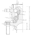
本発明に係る車輪支持用転がり軸受ユニット及びその製造方法の実施の形態を、図面を参照しながら詳細に説明する。図1は、車輪支持用転がり軸受ユニットの構造を示す断面図である。なお、本実施形態においては、車輪支持用転がり軸受ユニットを自動車等の車両に取り付けた状態において、車両の幅方向外側を向いた部分を外端側部分と称し、幅方向中央側を向いた部分を内端側部分と称する。すなわち、図1においては、左側が外端側となり、右側が内端側となる。 DESCRIPTION OF EMBODIMENTS Embodiments of a wheel bearing rolling bearing unit and a method for manufacturing the same according to the present invention will be described in detail with reference to the drawings. FIG. 1 is a sectional view showing the structure of a wheel bearing rolling bearing unit. In this embodiment, in a state where the wheel bearing rolling bearing unit is attached to a vehicle such as an automobile, the portion facing the width direction outside of the vehicle is referred to as an outer end side portion, and the portion facing the width direction center side Is referred to as an inner end portion. That is, in FIG. 1, the left side is the outer end side, and the right side is the inner end side.
図1の車輪支持用転がり軸受ユニット1は、ハブ輪2と、内輪3と、外輪4と、二列の転動体5,5と、転動体5を保持する保持器6,6と、を備えている。ハブ輪2の内端側部分には外径の小さい円筒部11が形成されており、該円筒部11に内輪3が圧入されている。そして、内輪3よりも内端側に突出している円筒部11の先端部分が径方向外方に加締め広げられて、内輪3とハブ輪2とが一体的に固定されている。ただし、内輪3とハブ輪2とを、ナットにより一体的に固定してもよい。この場合には、ナットによって内輪3に必要な予圧を付与することができる。そして、ハブ輪2及び内輪3の外方には、略円筒形状の外輪4が同心に配されている。なお、内輪3とハブ輪2とが一体的に固定されたものが、本発明の構成要件である内方部材に相当し、外輪4が本発明の構成要件である外方部材に相当する。
The wheel support rolling bearing unit 1 of FIG. 1 includes a hub wheel 2, an inner ring 3, an outer ring 4, two rows of
ハブ輪2の外周面の軸方向中間部及び内輪3の外周面には、それぞれ軌道面が形成されており、ハブ輪2の軌道面は第一内側軌道面20a、内輪3の軌道面は第二内側軌道面20bとされている。また、外輪4の内周面には、前記両内側軌道面20a,20bに対向する軌道面が形成されており、第一内側軌道面20aに対向する軌道面は第一外側軌道面21a、第二内側軌道面20bに対向する軌道面は第二外側軌道面21bとされている。さらに、第一内側軌道面20aと第一外側軌道面21aとの間、及び、第二内側軌道面20bと第二外側軌道面21bとの間には、それぞれ複数の転動体5が転動自在に配されている。なお、図示の例では、転動体として玉を使用しているが、車輪支持用転がり軸受ユニット1の用途等に応じて、ころを使用してもよい。
A raceway surface is formed on each of the axially intermediate portion of the outer peripheral surface of the hub wheel 2 and the outer peripheral surface of the inner ring 3. The raceway surface of the hub wheel 2 is the first
さらに、外輪4の外端側部分の内周面とハブ輪2の中間部の外周面との間には、シール装置7が設けられている。さらに、ハブ輪2の軸方向一端部(外端側部分U)には、軽量化のために凹部15が形成されている。
さらに、ハブ輪2の外周面の外端側部分には、図示しない車輪を固定するための車輪取り付け用フランジ10が径方向外方に突出して設けられている。そして、外輪4の外周面には、車輪取り付け用フランジ10から離間する側の端部に、懸架装置取り付け用フランジ13が径方向外方に突出して設けられている。
Further, a seal device 7 is provided between the inner peripheral surface of the outer end side portion of the outer ring 4 and the outer peripheral surface of the intermediate portion of the hub wheel 2. Further, a
Further, a
このような車輪支持用転がり軸受ユニット1を自動車等の車両に組み付けるには、懸架装置取り付け用フランジ13を図示しない懸架装置に固定し、車輪を車輪取り付け用フランジ10に固定する。その結果、車輪支持用転がり軸受ユニット1によって車輪が懸架装置に対し回転自在に支持される。すなわち、内輪3とハブ輪2とが一体的に固定されたものが回転輪となり、外輪4が固定輪(非回転輪)となる。
In order to assemble such a wheel support rolling bearing unit 1 to a vehicle such as an automobile, the suspension
このような車輪支持用転がり軸受ユニット1において、ハブ輪2,内輪3,及び外輪4は、鋼製素材に熱間鍛造を施して所定の形状に成形してなる熱間鍛造品である。熱間鍛造品の製造方法を、ハブ輪2を例にして説明する。ハブ輪2は複雑な形状で、1工程の熱間鍛造で成形することは困難なので、円柱形状の鋼製素材に複数工程の熱間鍛造を順次施して段階的に形状を変化させていくことにより成形する。 In such a wheel support rolling bearing unit 1, the hub wheel 2, the inner ring 3, and the outer ring 4 are hot forged products formed by hot forging a steel material into a predetermined shape. A method for manufacturing a hot forged product will be described using the hub wheel 2 as an example. The hub wheel 2 has a complicated shape, and it is difficult to form it by one-step hot forging. Therefore, multiple steps of hot forging are sequentially applied to a cylindrical steel material, and the shape is changed step by step. Molded by
熱間鍛造の工程数は特に限定されるものではないが、通常は3〜4工程である。例えば3工程の場合は、第一工程で据え込みを行い、第二工程で荒成形を行い、第三工程で仕上げ成形を行う。そして、これら複数工程の熱間鍛造を、下記の条件A,条件B,条件C,及び条件Dを満足するように行う。
条件A)熱間鍛造を開始するにあたって、まず鋼製素材を加熱するが、この加熱温度を1200℃以下とする。そして、熱間鍛造中の鋼製素材の温度が1200℃を超えないように制御する。もちろん、前記加熱温度は、後述する熱間鍛造時の加工温度と同一か又は加工温度よりも高温とする。
The number of hot forging steps is not particularly limited, but is usually 3 to 4 steps. For example, in the case of three steps, upsetting is performed in the first step, rough forming is performed in the second step, and finish forming is performed in the third step. And these multiple processes of hot forging are performed so as to satisfy the following conditions A, B, C, and D.
Condition A) When starting hot forging, the steel material is first heated, and the heating temperature is set to 1200 ° C. or lower. And it controls so that the temperature of the steel raw material in hot forging does not exceed 1200 degreeC. Of course, the heating temperature is the same as or higher than the processing temperature at the time of hot forging described later.
条件B)ハブ輪2のうち第一内側軌道面20aを含む外周面には、熱間鍛造の後に高周波焼入れが施されるが、凹部15が形成されている外端側部分Uや車輪取り付け用フランジ10には高周波焼入れは施されず、熱間鍛造が施されたままの硬化されていない表面状態で使用される。このような非調質部位は、すなわち、外端側部分Uや車輪取り付け用フランジ10などは、900℃以上1100℃以下の加工温度で熱間鍛造される。
条件C)この熱間鍛造によって、前記非調質部位には0.3以上1.5以下のvon Mises歪が導入される。
条件D)[前記加工温度]−150×[von Mises歪]なる式で定義される熱間鍛造パラメータPF が1000以下である。
Condition B) The outer peripheral surface including the first
Condition C) By this hot forging, a von Mises strain of 0.3 or more and 1.5 or less is introduced into the non-tempered portion.
Condition D) [the processing temperature] -150 × [von Mises strain] becomes hot forging parameters P F defined by the formula is 1000 or less.
次に、このような熱間鍛造の後に熱間鍛造品の冷却を行うが、この冷却工程を、下記の条件Eを満足するように行う。
条件E)冷却工程の冷却速度は0.25℃/s以上3℃/s以下である。
この冷却工程が終了したら外周面に高周波焼入れを施し、第一内側軌道面20aを形成する。そして、必要により旋削,研削,削孔等を施して、ハブ輪2を完成する。
Next, after such hot forging, the hot forged product is cooled, and this cooling step is performed so as to satisfy the following condition E.
Condition E) The cooling rate in the cooling step is 0.25 ° C./s or more and 3 ° C./s or less.
When this cooling step is completed, induction hardening is performed on the outer peripheral surface to form the first
このようにして製造されたハブ輪2は、温度,歪量,冷却速度が制御されつつ熱間鍛造及び冷却が行われたので、その前記非調質部位においては、日本工業規格JIS G0551に規定の方法で測定された旧オーステナイト結晶粒度が、粒度番号で6以上9以下となっている。そして、前記非調質部位は、軟質な初析フェライトの増加が抑制されており、適正なフェライト−パーライト組織を有しているので、優れた延性と強度とを有している。
また、熱間鍛造中の鋼製素材の温度が1200℃を超えないように制御されていたので、熱間鍛造において不可避の現象である脱炭現象が抑制され、脱炭深さは0.3mm以下となっている。その結果、脱炭現象による強度低下が抑制される。
Since the hub wheel 2 manufactured in this way was hot forged and cooled while the temperature, strain amount, and cooling rate were controlled, the non-heat treated part was specified in Japanese Industrial Standard JIS G0551. The prior austenite grain size measured by the above method is 6 or more and 9 or less in grain size number. And the said non-tempered site | part has the excellent ductility and intensity | strength, since the increase of the soft pro-eutectoid ferrite is suppressed and it has a suitable ferrite-pearlite structure | tissue.
Further, since the temperature of the steel material during hot forging was controlled so as not to exceed 1200 ° C., the decarburization phenomenon, which is an inevitable phenomenon in hot forging, was suppressed, and the decarburization depth was 0.3 mm. It is as follows. As a result, strength reduction due to the decarburization phenomenon is suppressed.
ハブ輪2の各部位には、車輪支持用転がり軸受ユニット1の駆動時に応力が負荷されることとなるが、焼入れが施されず熱間鍛造が施されたままの表面状態で使用される非調質部位は、強度がそれほど高くないため、応力に耐えることができず損傷が生じるおそれがある。しかしながら、上記のようにして製造したハブ輪2は、熱間鍛造の後に焼入れが施されず熱間鍛造が施されたままの表面状態で使用される非調質部位であっても高強度である。よって、車輪支持用転がり軸受ユニット1は、高強度で長寿命である。しかも、製造において高コストな焼入れを全体に施さなくてもよいので、車輪支持用転がり軸受ユニット1は安価である。 Each portion of the hub wheel 2 is subjected to stress when the wheel bearing rolling bearing unit 1 is driven, but is not used in a surface state that is not quenched and hot forged. The tempered portion is not so high in strength that it cannot withstand stress and may be damaged. However, the hub wheel 2 manufactured as described above has high strength even if it is a non-tempered part that is used in a surface state that is not quenched and subjected to hot forging after hot forging. is there. Therefore, the wheel-supporting rolling bearing unit 1 has high strength and long life. In addition, since it is not necessary to perform high-cost quenching throughout the manufacturing, the wheel bearing rolling bearing unit 1 is inexpensive.
特に、軽量化のために外端側部分Uの凹部15を大きくすると、該部分Uに負荷される応力が高くなり、ハブ輪2の軸方向長さaと凹部15の軸方向長さ(ハブ輪2の外端と凹部15の底部との間の軸方向距離)bとの比b/aが0.2以上であると、強度が十分ではない該部分Uに高い応力が負荷される可能性が高くなるが、上記のような条件を満たす熱間鍛造及び冷却を行えば非調質部位が高強度なので、高い応力に耐えることができ、軽量化が可能である。
In particular, if the
なお、本発明は、種々の車輪支持用転がり軸受ユニットに適用することが可能である。例えば、車輪取り付け用フランジがハブ輪や外輪と別体に設けられた、所謂第一世代の車輪支持用転がり軸受ユニット、車輪取り付け用フランジ又は懸架装置取り付け用フランジが外輪と一体に設けられた、所謂第二世代の車輪支持用転がり軸受ユニット、車輪取り付け用フランジ及び懸架装置取り付け用フランジがそれぞれ内輪及び外輪のいずれかと一体に設けられた、所謂第三世代の車輪支持用転がり軸受ユニットに適用することが可能である。 The present invention can be applied to various wheel bearing rolling bearing units. For example, a so-called first generation wheel support rolling bearing unit, a wheel mounting flange or a suspension device mounting flange provided integrally with the outer ring, where the wheel mounting flange is provided separately from the hub wheel and the outer ring, It is applied to a so-called third generation rolling bearing unit for wheel support, in which a so-called second generation wheel supporting rolling bearing unit, a wheel mounting flange and a suspension mounting flange are provided integrally with either the inner ring or the outer ring, respectively. It is possible.
〔実施例〕
以下に、実施例を示して、本発明をさらに具体的に説明する。円柱形状のS53C製素材に、前述と同様の3工程の熱間鍛造を施してハブ輪の形状に成形し、その後に冷却した。主に外端側部分に凹部を形成する工程である第二工程の熱間鍛造の条件(素材の加熱温度、並びに外端側部分における加工温度、von Mises歪、及び熱間鍛造パラメータPF )及び冷却工程の冷却速度を、表1に示す。
なお、加熱温度及び加工温度は、放射温度計を用いてワーク表面の温度を測定することにより求めた。また、von Mises歪は熱間鍛造時の形状寸法を変更することにより調整し、有限要素法を用いて求めた。さらに、冷却速度は、空冷ファンの風量と風速によって調整した。
〔Example〕
Hereinafter, the present invention will be described more specifically with reference to examples. The cylindrical S53C material was hot forged in the same three steps as described above to form a hub wheel shape, and then cooled. Conditions for hot forging in the second step, which is a step for forming a recess mainly in the outer end side portion (heating temperature of the material, processing temperature in the outer end side portion, von Mises strain, and hot forging parameter P F ) Table 1 shows the cooling rate of the cooling step.
The heating temperature and the processing temperature were determined by measuring the workpiece surface temperature using a radiation thermometer. Further, the von Mises strain was adjusted by changing the shape dimension during hot forging, and was determined using a finite element method. Furthermore, the cooling rate was adjusted by the air volume and air speed of the air cooling fan.

得られた熱間鍛造品にショットブラストを施して表面の酸化スケールを除去した後に、旋削加工,高周波焼入れ,焼戻し,研削加工,及び超仕上げ加工を施して、ハブ輪を得た。そして、このハブ輪を用いて、前述の車輪支持用転がり軸受ユニット1とほぼ同様の構成の車輪支持用転がり軸受ユニットを製造した。この車輪支持用転がり軸受ユニットの複列の軌道面間の軸方向距離は59mm、転動体である玉の個数は1列あたり12個、ハブ輪の軸方向長さaと凹部の軸方向長さbとの比b/aは0.3である。 The obtained hot forged product was shot blasted to remove the oxidized scale on the surface, and then subjected to turning, induction hardening, tempering, grinding, and superfinishing to obtain a hub wheel. And using this hub wheel, the wheel support rolling bearing unit of the structure substantially the same as the above-mentioned wheel support rolling bearing unit 1 was manufactured. The axial distance between the raceways of the double row of this rolling bearing unit for wheel support is 59 mm, the number of balls as rolling elements is 12 per row, the axial length a of the hub wheel and the axial length of the recess. The ratio b / a with b is 0.3.
この車輪支持用転がり軸受ユニットの車輪取り付け用フランジに、ハブボルトを介してアキシアル荷重3500N及びラジアル荷重4000Nを入力し、車輪支持用転がり軸受ユニットを回転速度300min-1で回転させて、繰り返し応力を付与した。そして、100時間回転を続け、凹部が形成された外端側部分の損傷(割れ)の有無を観察した。結果を表1に示す。なお、表1の「○」印は、100時間回転させても損傷が無かったことを示し、「△」印は、100時間回転後に亀裂が確認されたことを示し、「×」印は、100時間未満で破損し回転を続けられなかったことを示す。 An axial load of 3500 N and a radial load of 4000 N are input to the wheel mounting flange of the wheel support rolling bearing unit via hub bolts, and the wheel support rolling bearing unit is rotated at a rotational speed of 300 min −1 to repeatedly apply stress. did. And it continued rotation for 100 hours and observed the presence or absence of the damage (cracking) of the outer end side part in which the recess was formed. The results are shown in Table 1. In Table 1, “◯” indicates that there was no damage even after 100 hours of rotation, “Δ” indicates that cracks were confirmed after 100 hours of rotation, and “×” indicates that It shows that it was damaged in less than 100 hours and could not continue to rotate.
また、表1には、外端側部分の旧オーステナイト結晶粒度(日本工業規格JIS G0551に規定の方法で測定された旧オーステナイト結晶粒度)及び脱炭深さも示してある。旧オーステナイト結晶粒度の測定方法は、以下の通りである。ハブ輪を軸方向に平行な平面で破断し、その断面を研磨した後にナイタール腐食液でエッチングして、ハブ輪の外端側部分の最表面から1.0mm内側の部分(すなわち脱炭の生じていない部分)について旧オーステナイト結晶粒度を測定した。表1に記載の数値は粒度番号である。また、脱炭深さの測定方法は、以下の通りである。旧オーステナイト結晶粒度の場合と同様にエッチングして、その断面を金属顕微鏡で観察した。そして、脱炭に伴う変化が金属組織に見られなくなる最表面からの深さを、脱炭深さとした。 Table 1 also shows the prior austenite grain size (old austenite grain size measured by the method defined in Japanese Industrial Standard JIS G0551) and the decarburization depth of the outer end side portion. The method for measuring the prior austenite grain size is as follows. The hub wheel is broken in a plane parallel to the axial direction, the cross section is polished, and then etched with a nital etchant, so that a portion 1.0 mm inside from the outermost surface of the outer side of the hub wheel (that is, decarburization occurs) The austenite crystal grain size was measured for the unexposed portion. The numerical values shown in Table 1 are particle size numbers. Moreover, the measuring method of decarburization depth is as follows. Etching was performed in the same manner as in the case of the prior austenite grain size, and the cross section was observed with a metallographic microscope. And the depth from the outermost surface where the change accompanying decarburization is not seen in a metal structure was made into the decarburization depth.
非焼入れ部(非調質部位)の疲労強度を高めるためには、結晶粒を微細にすることが効果的である。非焼入れ部の結晶粒(フェライト−パーライト組織における旧オーステナイト結晶粒)は、熱間鍛造時に再結晶が生じて形成されるが、加工温度を低くするほど、導入される歪量を大きくするほど、結晶粒を微細にすることができる。
本発明者は、さらに鋭意検討を行った結果、熱間鍛造を前述の条件A,条件B,条件C,及び条件Dを満足するように行うことによって(実施例1〜8)、適正なフェライト−パーライト組織を有し且つ旧オーステナイト結晶粒度を粒度番号で6以上9以下とすることができ、高い疲労強度が得られることを見出した。そのため、実施例1〜8は、前述した条件で100時間回転させた後にもハブ輪の外端側部分に破損は見られず、優れた疲労強度を有していた。
In order to increase the fatigue strength of the non-quenched part (non-tempered part), it is effective to make the crystal grains fine. The crystal grains of the non-quenched part (former austenite crystal grains in the ferrite-pearlite structure) are formed by recrystallization during hot forging, but the lower the processing temperature, the larger the strain introduced, Crystal grains can be made fine.
As a result of further diligent investigations, the present inventor conducted hot forging so as to satisfy the above-mentioned conditions A, B, C, and D (Examples 1 to 8). -It has discovered that it has a pearlite structure | tissue and can make a prior-austenite
比較例3のように加工温度が900℃未満であると、結晶粒が過度に微細となるため、初析フェライトが増加して硬さが低下する。そのため、疲労強度が不十分であった。また、比較例1のように加工温度が1100℃超過であると、十分なvon Mises歪を加えても結晶粒が微細にならないため、十分な疲労強度が得られなかった。
さらに、比較例4のようにvon Mises歪が0.3未満であると、十分に再結晶できないため、加工温度が適切であっても結晶粒が微細にならず、高い疲労強度が得られなかった。さらに、von Mises歪が1.5超過であると、加工発熱が生じて、かえって結晶粒が大きくなってしまう場合や、加工温度が低い場合には金型への負荷が大きくなるおそれがあるため、好ましくない。
When the processing temperature is less than 900 ° C. as in Comparative Example 3, the crystal grains become excessively fine, so that the pro-eutectoid ferrite increases and the hardness decreases. Therefore, the fatigue strength was insufficient. Further, when the processing temperature was over 1100 ° C. as in Comparative Example 1, the crystal grains did not become fine even when sufficient von Mises strain was applied, so that sufficient fatigue strength could not be obtained.
Furthermore, if the von Mises strain is less than 0.3 as in Comparative Example 4, the crystal cannot be sufficiently recrystallized, so even if the processing temperature is appropriate, the crystal grains do not become fine and high fatigue strength cannot be obtained. It was. Furthermore, if the von Mises strain is more than 1.5, processing heat is generated and the crystal grains become larger, or the load on the mold may increase when the processing temperature is low. It is not preferable.
さらに、比較例2のように、加工温度及びvon Mises歪が適正であっても、熱間鍛造パラメータPF が1000超過であると、結晶粒が微細にならず十分な疲労強度が得られなかった。
ただし、結晶粒が過度に微細であると、軟質な初析フェライトが増加してしまうため、硬さが低下して、かえって疲労強度が低下するおそれがある。初析フェライトは、結晶粒が大きいほど、熱間鍛造後の冷却工程における冷却速度が速いほど少量となる。すなわち、冷却速度を0.25℃/s以上とすることによって、硬さの低下を抑制することができる。一方、冷却速度が3℃/sよりも大きいと、局部的にマルテンサイト変態を生じるため、割れ等が発生するおそれがある。比較例5は冷却速度が遅いため、疲労強度が不十分であった。なお、本発明における冷却速度は、熱間鍛造の終了後から550℃に低下するまでの冷却速度を意味する。
Furthermore, as in Comparative Example 2, even a fair processing temperature and von Mises strain, the hot forging parameters P F is a 1000 exceeded, no sufficient fatigue strength grain does not become fine is obtained It was.
However, if the crystal grains are excessively fine, soft pro-eutectoid ferrite is increased, so that the hardness is lowered and the fatigue strength may be lowered. The amount of pro-eutectoid ferrite becomes smaller as the crystal grain becomes larger and the cooling rate in the cooling step after hot forging becomes faster. That is, by setting the cooling rate to 0.25 ° C./s or more, it is possible to suppress a decrease in hardness. On the other hand, when the cooling rate is higher than 3 ° C./s, martensitic transformation is locally generated, so that there is a possibility that cracking or the like may occur. Since the comparative example 5 had a slow cooling rate, the fatigue strength was insufficient. In addition, the cooling rate in this invention means the cooling rate until it falls to 550 degreeC after completion | finish of hot forging.
また、熱間鍛造においては脱炭は不可避の現象であるが、脱炭により硬さが低下するため疲労強度も低下してしまう。比較例6,7は、加熱温度が1200℃超過で脱炭深さが大きかったため、疲労強度が不十分となった。
なお、ショットブラストを行ったが、これは酸化スケールを除去するだけでなく、ハブ輪の表面に圧縮の残留応力を付与できるため、熱間鍛造の後に焼入れが施されず熱間鍛造が施されたままの表面状態で使用される非調質部位の強度向上に寄与する。比較例6,7は、脱炭深さが大きく、ショットブラストの効果が十分に得られなかったと考えられるので、このことも疲労強度が不十分となった一因であると考えられる。
In hot forging, decarburization is an inevitable phenomenon, but since the hardness is reduced by decarburization, the fatigue strength is also reduced. In Comparative Examples 6 and 7, the heating temperature exceeded 1200 ° C. and the decarburization depth was large, so the fatigue strength was insufficient.
Although shot blasting was performed, this not only removed the oxide scale but also applied compressive residual stress to the surface of the hub wheel, so that hot forging was performed without being quenched after hot forging. This contributes to improving the strength of non-tempered parts that are used in the raw surface state. In Comparative Examples 6 and 7, the decarburization depth is large, and it is considered that the effect of shot blasting was not sufficiently obtained, so this is also considered to be a cause of insufficient fatigue strength.
1 車輪支持用転がり軸受ユニット
2 ハブ輪
3 内輪
4 外輪
5 転動体
10 車輪取り付け用フランジ
13 懸架装置取り付け用フランジ
15 凹部
20a 第一内側軌道面
20b 第二内側軌道面
21a 第一外側軌道面
21b 第二外側軌道面
a ハブ輪の軸方向長さ
b 凹部の軸方向長さ
U 外端側部分
DESCRIPTION OF SYMBOLS 1 Wheel support rolling bearing unit 2 Hub ring 3 Inner ring 4
Claims (4)
鋼製素材に熱間鍛造を施して所定の形状に成形した後に、少なくとも前記軌道面に高周波焼入れを施して硬化することにより、前記内方部材及び前記外方部材の少なくとも一方を得るとともに、
前記熱間鍛造を、下記の条件A,条件B,条件C,及び条件Dを満足するように行い、前記熱間鍛造と前記高周波焼入れの間に行う冷却工程を、下記の条件Eを満足するように行うことを特徴とする車輪支持用転がり軸受ユニットの製造方法。
条件A)前記熱間鍛造時における前記鋼製素材の温度を1200℃以下とする。
条件B)前記内方部材又は前記外方部材のうち、前記高周波焼入れは施されず前記熱間鍛造が施されたままの表面状態で使用される非調質部位は、900℃以上1100℃以下の加工温度で熱間鍛造される。
条件C)前記熱間鍛造によって、前記非調質部位には0.3以上1.5以下のvon Mises歪が導入される。
条件D)[前記加工温度]−150×[前記von Mises歪]なる式で定義される熱間鍛造パラメータPF が1000以下である。
条件E)前記冷却工程の冷却速度は0.25℃/s以上3℃/s以下である。 An inner member having a raceway surface on an outer peripheral surface; an outer member having a raceway surface facing the raceway surface of the inner member; and the raceway surface of the inner member. And a plurality of rolling elements arranged so as to be freely rollable between the outer member and the raceway surface of the outer member, when manufacturing a wheel support rolling bearing unit,
After performing hot forging on a steel material and forming it into a predetermined shape, at least one of the inner member and the outer member is obtained by performing induction hardening on at least the raceway surface and curing,
The hot forging is performed so as to satisfy the following conditions A, B, C, and D, and the cooling process performed between the hot forging and the induction hardening satisfies the following condition E: A method for manufacturing a wheel-supporting rolling bearing unit, characterized in that:
Condition A) The temperature of the steel material during the hot forging is set to 1200 ° C. or less.
Condition B) Of the inner member or the outer member, the non-tempered portion used in the surface state where the induction hardening is not performed and the hot forging is performed is 900 ° C. or higher and 1100 ° C. or lower. Hot forging at a processing temperature of
Condition C) By the hot forging, a von Mises strain of 0.3 to 1.5 is introduced into the non-tempered portion.
Condition D) [the processing temperature] -150 × [the von Mises strain] becomes hot forging parameters P F defined by the formula is 1000 or less.
Condition E) The cooling rate in the cooling step is 0.25 ° C./s or more and 3 ° C./s or less.
請求項1に記載の車輪支持用転がり軸受ユニットの製造方法で製造され、前記非調質部位においては、日本工業規格JIS G0551に規定の方法で測定された旧オーステナイト結晶粒度が、粒度番号で6以上9以下となっており、且つ、脱炭深さが0.3mm以下であることを特徴とする車輪支持用転がり軸受ユニット。 An inner member having a raceway surface on an outer peripheral surface; an outer member having a raceway surface facing the raceway surface of the inner member; and the raceway surface of the inner member. A rolling bearing unit for supporting a wheel, comprising: a plurality of rolling elements that are freely rollable between the outer race member and the raceway surface of the outer member;
The prior austenite grain size measured by the method defined in Japanese Industrial Standard JIS G0551 in the non-heat treated portion is 6 in terms of the grain size number. A rolling bearing unit for supporting a wheel, wherein the rolling bearing unit is 9 or less and has a decarburization depth of 0.3 mm or less.
Priority Applications (1)
| Application Number | Priority Date | Filing Date | Title |
|---|---|---|---|
| JP2008169567A JP5195081B2 (en) | 2008-06-27 | 2008-06-27 | Rolling bearing unit for wheel support and manufacturing method thereof |
Applications Claiming Priority (1)
| Application Number | Priority Date | Filing Date | Title |
|---|---|---|---|
| JP2008169567A JP5195081B2 (en) | 2008-06-27 | 2008-06-27 | Rolling bearing unit for wheel support and manufacturing method thereof |
Publications (2)
| Publication Number | Publication Date |
|---|---|
| JP2010007798A true JP2010007798A (en) | 2010-01-14 |
| JP5195081B2 JP5195081B2 (en) | 2013-05-08 |
Family
ID=41588532
Family Applications (1)
| Application Number | Title | Priority Date | Filing Date |
|---|---|---|---|
| JP2008169567A Expired - Fee Related JP5195081B2 (en) | 2008-06-27 | 2008-06-27 | Rolling bearing unit for wheel support and manufacturing method thereof |
Country Status (1)
| Country | Link |
|---|---|
| JP (1) | JP5195081B2 (en) |
Cited By (2)
| Publication number | Priority date | Publication date | Assignee | Title |
|---|---|---|---|---|
| DE102022104075A1 (en) | 2021-03-26 | 2022-09-29 | Schaeffler Technologies AG & Co. KG | Process for producing a component for a wheel bearing and wheel bearing with such a component |
| WO2022199738A1 (en) | 2021-03-26 | 2022-09-29 | Schaeffler Technologies AG & Co. KG | Process for producing a component for a wheel bearing and wheel bearing comprising such a component |
Citations (7)
| Publication number | Priority date | Publication date | Assignee | Title |
|---|---|---|---|---|
| JPH11151904A (en) * | 1997-09-16 | 1999-06-08 | Nippon Seiko Kk | Rolling bearing unit for wheel |
| JP2004232669A (en) * | 2003-01-28 | 2004-08-19 | Nsk Ltd | Roller bearing unit for wheel support |
| JP2004346415A (en) * | 2003-05-26 | 2004-12-09 | Nippon Steel Corp | Ultrahigh-temperature hot-forged non-heat-treated parts and manufacturing method therefor |
| JP2006052790A (en) * | 2004-08-11 | 2006-02-23 | Ntn Corp | Roller bearing |
| JP2007107647A (en) * | 2005-10-14 | 2007-04-26 | Nsk Ltd | Rolling bearing device for supporting wheel |
| JP2007211314A (en) * | 2006-02-10 | 2007-08-23 | Sumitomo Metal Ind Ltd | Method for hot-forging non-heat-treated parts |
| JP2008133530A (en) * | 2006-10-31 | 2008-06-12 | Jfe Steel Kk | Bearing steel component and its production method, and bearing |
-
2008
- 2008-06-27 JP JP2008169567A patent/JP5195081B2/en not_active Expired - Fee Related
Patent Citations (7)
| Publication number | Priority date | Publication date | Assignee | Title |
|---|---|---|---|---|
| JPH11151904A (en) * | 1997-09-16 | 1999-06-08 | Nippon Seiko Kk | Rolling bearing unit for wheel |
| JP2004232669A (en) * | 2003-01-28 | 2004-08-19 | Nsk Ltd | Roller bearing unit for wheel support |
| JP2004346415A (en) * | 2003-05-26 | 2004-12-09 | Nippon Steel Corp | Ultrahigh-temperature hot-forged non-heat-treated parts and manufacturing method therefor |
| JP2006052790A (en) * | 2004-08-11 | 2006-02-23 | Ntn Corp | Roller bearing |
| JP2007107647A (en) * | 2005-10-14 | 2007-04-26 | Nsk Ltd | Rolling bearing device for supporting wheel |
| JP2007211314A (en) * | 2006-02-10 | 2007-08-23 | Sumitomo Metal Ind Ltd | Method for hot-forging non-heat-treated parts |
| JP2008133530A (en) * | 2006-10-31 | 2008-06-12 | Jfe Steel Kk | Bearing steel component and its production method, and bearing |
Cited By (2)
| Publication number | Priority date | Publication date | Assignee | Title |
|---|---|---|---|---|
| DE102022104075A1 (en) | 2021-03-26 | 2022-09-29 | Schaeffler Technologies AG & Co. KG | Process for producing a component for a wheel bearing and wheel bearing with such a component |
| WO2022199738A1 (en) | 2021-03-26 | 2022-09-29 | Schaeffler Technologies AG & Co. KG | Process for producing a component for a wheel bearing and wheel bearing comprising such a component |
Also Published As
| Publication number | Publication date |
|---|---|
| JP5195081B2 (en) | 2013-05-08 |
Similar Documents
| Publication | Publication Date | Title |
|---|---|---|
| JP5121168B2 (en) | Rolling member manufacturing method and rolling bearing manufacturing method | |
| US20090106980A1 (en) | Process for Producing Bearing Device for Wheel | |
| JP2006200700A (en) | Rolling bearing device for supporting wheel | |
| JP2006291250A (en) | Rolling bearing unit for wheel supporting | |
| JP4423858B2 (en) | Manufacturing method of wheel bearing rolling bearing unit | |
| JP5136146B2 (en) | Manufacturing method of wheel bearing rolling bearing unit | |
| JP4893585B2 (en) | Manufacturing method of wheel bearing rolling bearing unit | |
| JP5195081B2 (en) | Rolling bearing unit for wheel support and manufacturing method thereof | |
| JP2006064036A (en) | Bearing device for supporting axle | |
| JP2007022464A (en) | Bearing device for wheels | |
| JP2005113186A (en) | Rolling bearing ring and its producing method, and rolling bearing | |
| JP2008169941A (en) | Wheel bearing device | |
| JP2006142916A (en) | Rolling bearing unit for supporting vehicle wheel | |
| JP2005145313A (en) | Rolling bearing unit for supporting vehicle wheel | |
| JP2006329287A (en) | Wheel supporting rolling bearing unit and its inner ring manufacturing method | |
| JP5644881B2 (en) | Manufacturing method of wheel bearing rolling bearing device | |
| JP5050587B2 (en) | Rolling bearing device for wheel support | |
| JP2010013039A (en) | Rolling bearing unit for wheel support and method of manufacturing the same | |
| JP2008266667A (en) | Rolling bearing device for supporting wheel | |
| JP5195089B2 (en) | Hub unit bearing and manufacturing method thereof | |
| JP2006153188A (en) | Roller bearing system for supporting wheel | |
| JP4225061B2 (en) | Rolling bearing unit for wheel support | |
| JP2007107647A (en) | Rolling bearing device for supporting wheel | |
| JP2007038899A (en) | Bearing device for vehicle wheel | |
| JP2012192818A (en) | Bearing device for wheel |
Legal Events
| Date | Code | Title | Description |
|---|---|---|---|
| RD03 | Notification of appointment of power of attorney |
Free format text: JAPANESE INTERMEDIATE CODE: A7423 Effective date: 20101022 |
|
| RD04 | Notification of resignation of power of attorney |
Free format text: JAPANESE INTERMEDIATE CODE: A7424 Effective date: 20101022 |
|
| A621 | Written request for application examination |
Free format text: JAPANESE INTERMEDIATE CODE: A621 Effective date: 20110608 |
|
| RD04 | Notification of resignation of power of attorney |
Free format text: JAPANESE INTERMEDIATE CODE: A7424 Effective date: 20111216 |
|
| A977 | Report on retrieval |
Free format text: JAPANESE INTERMEDIATE CODE: A971007 Effective date: 20120413 |
|
| A131 | Notification of reasons for refusal |
Free format text: JAPANESE INTERMEDIATE CODE: A131 Effective date: 20120508 |
|
| TRDD | Decision of grant or rejection written | ||
| A01 | Written decision to grant a patent or to grant a registration (utility model) |
Free format text: JAPANESE INTERMEDIATE CODE: A01 Effective date: 20130108 |
|
| A61 | First payment of annual fees (during grant procedure) |
Free format text: JAPANESE INTERMEDIATE CODE: A61 Effective date: 20130121 |
|
| FPAY | Renewal fee payment (event date is renewal date of database) |
Free format text: PAYMENT UNTIL: 20160215 Year of fee payment: 3 |
|
| R150 | Certificate of patent or registration of utility model |
Free format text: JAPANESE INTERMEDIATE CODE: R150 |
|
| LAPS | Cancellation because of no payment of annual fees |