EP1707678A2 - Strassenkehrmaschine mit einem mechanischen Vakuumfilter zum Sammeln von Müll - Google Patents
Strassenkehrmaschine mit einem mechanischen Vakuumfilter zum Sammeln von Müll Download PDFInfo
- Publication number
- EP1707678A2 EP1707678A2 EP06005728A EP06005728A EP1707678A2 EP 1707678 A2 EP1707678 A2 EP 1707678A2 EP 06005728 A EP06005728 A EP 06005728A EP 06005728 A EP06005728 A EP 06005728A EP 1707678 A2 EP1707678 A2 EP 1707678A2
- Authority
- EP
- European Patent Office
- Prior art keywords
- filter
- hopper
- brush
- refuse
- street sweeper
- Prior art date
- Legal status (The legal status is an assumption and is not a legal conclusion. Google has not performed a legal analysis and makes no representation as to the accuracy of the status listed.)
- Withdrawn
Links
Images


Classifications
-
- E—FIXED CONSTRUCTIONS
- E01—CONSTRUCTION OF ROADS, RAILWAYS, OR BRIDGES
- E01H—STREET CLEANING; CLEANING OF PERMANENT WAYS; CLEANING BEACHES; DISPERSING OR PREVENTING FOG IN GENERAL CLEANING STREET OR RAILWAY FURNITURE OR TUNNEL WALLS
- E01H1/00—Removing undesirable matter from roads or like surfaces, with or without moistening of the surface
- E01H1/08—Pneumatically dislodging or taking-up undesirable matter or small objects; Drying by heat only or by streams of gas; Cleaning by projecting abrasive particles
- E01H1/0827—Dislodging by suction; Mechanical dislodging-cleaning apparatus with independent or dependent exhaust, e.g. dislodging-sweeping machines with independent suction nozzles ; Mechanical loosening devices working under vacuum
- E01H1/0854—Apparatus in which the mechanically dislodged dirt is partially sucked-off, e.g. dislodging- sweeping apparatus with dirt collector in brush housing or dirt container
-
- E—FIXED CONSTRUCTIONS
- E01—CONSTRUCTION OF ROADS, RAILWAYS, OR BRIDGES
- E01H—STREET CLEANING; CLEANING OF PERMANENT WAYS; CLEANING BEACHES; DISPERSING OR PREVENTING FOG IN GENERAL CLEANING STREET OR RAILWAY FURNITURE OR TUNNEL WALLS
- E01H1/00—Removing undesirable matter from roads or like surfaces, with or without moistening of the surface
- E01H1/08—Pneumatically dislodging or taking-up undesirable matter or small objects; Drying by heat only or by streams of gas; Cleaning by projecting abrasive particles
- E01H1/0863—Apparatus loosening or removing the dirt by blowing and subsequently dislodging it at least partially by suction ; Combined suction and blowing nozzles
- E01H1/0872—Apparatus loosening or removing the dirt by blowing and subsequently dislodging it at least partially by suction ; Combined suction and blowing nozzles with mechanical loosening or feeding instruments for the dirt to be removed pneumatically, e.g. brushes, scrapers
Definitions
- the invention relates to a street sweeper having a mechanical vacuum filter system for refuse collection.
- Sweepers are already known, which have a chassis on which a hopper is mounted for receiving refuse, to be conveyed into such hopper through a number of devices, including:
- the conveyor device and the suction means cooperate to convey refuse into the receiving hopper, in which a negative pressure is created by one or more centrifugal valves.
- the air sucked in by the hopper is filtered by a filter unit placed in the hopper, before passing through the fans and being discharged to the atmosphere.
- Another type of street sweepers only has a vacuum system for conveying refuse into the receiving hopper.
- This type of sweeper requires a considerable air flow to convey refuse into the receiving hopper, which involves filtering problems.
- the object of this invention is to allow fine particulate matter to be collected and held by the sweeper for disposal as special refuse in accordance with applicable standards.
- a street sweeper having a mechanical vacuum filter system for refuse collection, which is characterized as set forth in the annexed claims, and mainly in that it provides a combination of an air blowing system located behind the cylindrical brush against the ground and all along the brush, and a second fine particulate filter through which the air sucked in by the fans placed in series with the first filter in the refuse receiving hopper is conveyed.
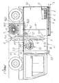
- a sweeper is generally designated with numeral 1.
- the sweeper has a chassis 2, supporting a cylindrical brush 6, which is placed between the front and rear wheels and rotates transverse to the chassis 2 and parallel to the axes of rotation of the wheels, so that the bristles of said brushes are in contact with the underlying road surface.
- the axis of rotation of the brush 6 is supported in such a manner as to allow height adjustment of the brush relative to the chassis 2, and to further accommodate appropriate vertical settling oscillations upon contact with any asperity or obstacles on the road surface.
- the chassis 2 also has a channel 7 for a belt conveyor-elevator 9 having a plurality of shelves 10 for simultaneously collecting and lifting the particulate matter removed by the brush 6.
- the conveyor belt 9 is driven by well-known drive means.
- the conveyor elevator belt runs within the channel 7 which has, at the lower section of the conveyor, a first aperture 14a adjacent the brush 6 for instant conveyance of the particulate matter removed by the counter-clockwise rotation of the brush.
- the chassis 2 further includes a container, or tipping hopper 12 with a storage chamber 13 formed therein, which is connected to the channel 7 through a second aperture 14b, formed about level with the upper end of the conveyor-elevator belt 9.
- a means is provided in the container 12 for suctioning the particulate matter removed by the brush 6.
- This suction means is an aspirator 15 which generates a negative pressure in the storage chamber 13 to cause the particulate matter to be drawn up toward the conveyor belt 9 and the hopper.
- the aspirator 15 is operatively upstream connected to a first coarse filter or pre-filter 16 (about 20 pm) for purification of air from the particulate matter sucked in by the hopper and communicated downstream, through a channel 5, with a chamber 3 that contains a fine particulate filter 4.
- the air that enters the chamber 3 above the hopper is discharged to the atmosphere after passing through the filter 4.
- a first filtering or pre-filtering step separates the coarse matter
- a second filtering step separates fine particulate by using a so-called absolute filter, i.e. having an efficiency of 99.99% at 0.3 ⁇ m, so that the air discharged to the atmosphere is substantially free of any particulate matter or anyway complying with applicable standards.
- the means for blowing air to the area of the road surface facing the brush 6 consist of a blower, designated with numeral 19, which is upstream connected by a first regulating valve 20 to a first upwardly directed conduit 21, for connection to an overlying filter 22 in communication with the atmosphere.
- atmospheric air may enter the filter 22 and be conveyed through the conduit 21 to the blower 19.
- the blower is downstream connected by a second regulating valve 23 to a second flexible conduit 24, extending in a substantially horizontal direction.
- a T-fitting 28 is installed in a section 26 of the conduit 24, with two pipes 29a and 29a branching off therefrom, and opening out below the storage chamber 13, behind the underlying brush 6, into an area facing opposite the first aperture 14a of the channel 7.
- the pipes 29a and 29b diverge to define respective sections, designated with numerals 30a and 30b, which open out into an underlying tube 31, which is disposed transverse to the chassis 2, level with the ground or road surface.
- the ends of the tube 31, designated with numerals 32a and 32b, are closed and adjacent to their respective connections with the sections 30a and 30b.
- the tube 31 has a plurality of holes or nozzles 33 on the surface adjacent the ground, which are turned toward the brush and the ground to allow the air delivered by the blower to be blown to the area of the road surface that comes in contact with the brush 6.
- holes or nozzles are arranged in succession and predeterminedly spaced, preferably all along the tube 31, so that the air is evenly distributed across the area of the ground interacting with the brush 6.
- the air ejected from the holes 33 shall have such a pressure as to allow that, immediately before the brushing action of the brush 6, particulate matter and residual dirt may be removed from the porous areas of the road surface that are not easily reached by the bristles of the brushes 6.
- the tube 31 is connected to support means for automatic position settling thereof, which consist of two chains 34a and 34b associated to the ends 32a and 32b of the tube 31.
- the invention was found to fulfill the intended objects of lifting fine particulate matter from the road surface and holding it in the filters 4, which may be removed once a predetermined clogging position is reached, as indicated by suitable well-known devices, installed in the sweeper cabin.
- a tube 40 is provided to allow communication between the operating area of the cylindrical brush 6 and the upper portion of the hopper 12, so that a negative pressure may be also generated in the operating chamber of the brush 6.
Applications Claiming Priority (1)
| Application Number | Priority Date | Filing Date | Title |
|---|---|---|---|
| ITPR20050012 ITPR20050012A1 (it) | 2005-03-30 | 2005-03-30 | Macchina spazzatrice stradale con sistema meccanico aspirante filtrante per la raccolta dei rifiuti. |
Publications (2)
| Publication Number | Publication Date |
|---|---|
| EP1707678A2 true EP1707678A2 (de) | 2006-10-04 |
| EP1707678A3 EP1707678A3 (de) | 2008-03-26 |
Family
ID=36608643
Family Applications (1)
| Application Number | Title | Priority Date | Filing Date |
|---|---|---|---|
| EP06005728A Withdrawn EP1707678A3 (de) | 2005-03-30 | 2006-03-21 | Strassenkehrmaschine mit einem mechanischen Vakuumfilter zum Sammeln von Müll |
Country Status (2)
| Country | Link |
|---|---|
| EP (1) | EP1707678A3 (de) |
| IT (1) | ITPR20050012A1 (de) |
Cited By (6)
| Publication number | Priority date | Publication date | Assignee | Title |
|---|---|---|---|---|
| EP2203599A1 (de) * | 2007-09-26 | 2010-07-07 | Roger Vanderlinden | Kehrmaschine zur verwendung mit einem fahrzeug und mit einer beweglichen blasluftdüse |
| FR2950084A1 (fr) * | 2009-09-14 | 2011-03-18 | Icee Gmbh | Cuve de reception pour dechets preleves par un vehicule de voirie comportant des moyens de filtration et de separation des particules aspirees |
| CN106702937A (zh) * | 2017-03-07 | 2017-05-24 | 浙江工业大学 | 一种自动清扫的清洁车及其自动驾驶方法 |
| DE102018104116B3 (de) | 2018-02-23 | 2019-08-08 | Aebi Schmidt Deutschland Gmbh | Kehrmaschine |
| CN110106819A (zh) * | 2019-06-17 | 2019-08-09 | 滨州禾夏汽车用品有限公司 | 一种适用于非机动车道的环卫工自动清洁小车 |
| US11401670B2 (en) | 2017-12-20 | 2022-08-02 | Enilton Teixeira Goethel | Self-propelled equipment for street sweeping and/or weeding |
Citations (6)
| Publication number | Priority date | Publication date | Assignee | Title |
|---|---|---|---|---|
| US4310944A (en) * | 1978-01-30 | 1982-01-19 | Tennant Company | Surface maintenance machine having air recirculation |
| US4754521A (en) * | 1986-07-31 | 1988-07-05 | Dulevo S.P.A | Street sweeper machine for trash collecting |
| FR2685366A1 (fr) * | 1991-12-18 | 1993-06-25 | Nicolas | Dispositif porte de nettoyage de voierie et industriel. |
| US6154922A (en) * | 1999-02-22 | 2000-12-05 | Vanderlinden; Roger P. | Self-propelled factory floor cleaning vehicle |
| US6195837B1 (en) * | 1999-02-22 | 2001-03-06 | Roger P. Vanderlinden | Debris suctioning and separating apparatus for use in a surface sweeping vehicle having a mechanical debris elevator |
| US20050060834A1 (en) * | 2002-02-13 | 2005-03-24 | Strauser Daniel P. | Debris collection systems, vehicles, and methods |
-
2005
- 2005-03-30 IT ITPR20050012 patent/ITPR20050012A1/it unknown
-
2006
- 2006-03-21 EP EP06005728A patent/EP1707678A3/de not_active Withdrawn
Patent Citations (6)
| Publication number | Priority date | Publication date | Assignee | Title |
|---|---|---|---|---|
| US4310944A (en) * | 1978-01-30 | 1982-01-19 | Tennant Company | Surface maintenance machine having air recirculation |
| US4754521A (en) * | 1986-07-31 | 1988-07-05 | Dulevo S.P.A | Street sweeper machine for trash collecting |
| FR2685366A1 (fr) * | 1991-12-18 | 1993-06-25 | Nicolas | Dispositif porte de nettoyage de voierie et industriel. |
| US6154922A (en) * | 1999-02-22 | 2000-12-05 | Vanderlinden; Roger P. | Self-propelled factory floor cleaning vehicle |
| US6195837B1 (en) * | 1999-02-22 | 2001-03-06 | Roger P. Vanderlinden | Debris suctioning and separating apparatus for use in a surface sweeping vehicle having a mechanical debris elevator |
| US20050060834A1 (en) * | 2002-02-13 | 2005-03-24 | Strauser Daniel P. | Debris collection systems, vehicles, and methods |
Cited By (8)
| Publication number | Priority date | Publication date | Assignee | Title |
|---|---|---|---|---|
| EP2203599A1 (de) * | 2007-09-26 | 2010-07-07 | Roger Vanderlinden | Kehrmaschine zur verwendung mit einem fahrzeug und mit einer beweglichen blasluftdüse |
| EP2203599A4 (de) * | 2007-09-26 | 2012-11-28 | Roger Vanderlinden | Kehrmaschine zur verwendung mit einem fahrzeug und mit einer beweglichen blasluftdüse |
| FR2950084A1 (fr) * | 2009-09-14 | 2011-03-18 | Icee Gmbh | Cuve de reception pour dechets preleves par un vehicule de voirie comportant des moyens de filtration et de separation des particules aspirees |
| EP2299000A3 (de) * | 2009-09-14 | 2013-04-03 | Nilfisk-Advance A/S | Aufnahmebehälter für Abfälle, die von einem Straßenreinigungsfahrzeug aufgenommen werden |
| CN106702937A (zh) * | 2017-03-07 | 2017-05-24 | 浙江工业大学 | 一种自动清扫的清洁车及其自动驾驶方法 |
| US11401670B2 (en) | 2017-12-20 | 2022-08-02 | Enilton Teixeira Goethel | Self-propelled equipment for street sweeping and/or weeding |
| DE102018104116B3 (de) | 2018-02-23 | 2019-08-08 | Aebi Schmidt Deutschland Gmbh | Kehrmaschine |
| CN110106819A (zh) * | 2019-06-17 | 2019-08-09 | 滨州禾夏汽车用品有限公司 | 一种适用于非机动车道的环卫工自动清洁小车 |
Also Published As
| Publication number | Publication date |
|---|---|
| ITPR20050012A1 (it) | 2006-09-30 |
| EP1707678A3 (de) | 2008-03-26 |
Similar Documents
| Publication | Publication Date | Title |
|---|---|---|
| EP1772564B1 (de) | Reinigungseinheit für Strassen und Ähnlichem | |
| EP1707678A2 (de) | Strassenkehrmaschine mit einem mechanischen Vakuumfilter zum Sammeln von Müll | |
| US7867323B2 (en) | Apparatus for on-site cleaning of landscape rock | |
| US6742219B2 (en) | Air sweeping apparatus | |
| KR101898100B1 (ko) | 건식 청소차 | |
| KR101970624B1 (ko) | 펄싱 작업에 필터링 공기를 이용하는 도로분진 흡입청소차 | |
| US4599016A (en) | Cyclone apparatus for pneumatically moving granular matter | |
| CN105780698A (zh) | 车辆辅助工作装置、清洁系统以及方法 | |
| KR101552163B1 (ko) | 고효율 건식 노면 청소차 | |
| KR100959401B1 (ko) | 도로면의 비점오염을 제거하기 위한 고압살수장치가 구비된 진공흡입 청소차량 | |
| KR102111515B1 (ko) | 먼지필터를 구비한 노면 청소차 | |
| KR101831941B1 (ko) | 철도차량용 미세먼지 제거장치 | |
| KR102000240B1 (ko) | 대기 미세먼지 정화장치를 포함하는 청소차 | |
| KR100883086B1 (ko) | 공조시스템을 이용한 도로 청소방법 | |
| CN211815905U (zh) | 一种多功能道路污染清除车 | |
| CN106120624B (zh) | 一种具有扬尘处理装置的电动地面清扫机 | |
| KR102298494B1 (ko) | 차량용 도로 청소 흡입 장치 | |
| KR20220101957A (ko) | 워터필터가 구비된 도로분진 흡입차량 | |
| CN209194429U (zh) | 一种环卫车吸尘装置 | |
| CN1791347A (zh) | 用于去除来自一个分离室的微粒的装置 | |
| CN211256604U (zh) | 道路铣刨机 | |
| CN1084417C (zh) | 吹吸式高速射流扫路机 | |
| KR20140039272A (ko) | 공압식 재료 이송시스템에서의 방법 및 장치 | |
| KR102628972B1 (ko) | 오수 정화가 가능한 고압 살수 노면 청소차 시스템 | |
| CN211571550U (zh) | 一种城市街道垃圾清运车 |
Legal Events
| Date | Code | Title | Description |
|---|---|---|---|
| PUAI | Public reference made under article 153(3) epc to a published international application that has entered the european phase |
Free format text: ORIGINAL CODE: 0009012 |
|
| AK | Designated contracting states |
Kind code of ref document: A2 Designated state(s): AT BE BG CH CY CZ DE DK EE ES FI FR GB GR HU IE IS IT LI LT LU LV MC NL PL PT RO SE SI SK TR |
|
| AX | Request for extension of the european patent |
Extension state: AL BA HR MK YU |
|
| PUAL | Search report despatched |
Free format text: ORIGINAL CODE: 0009013 |
|
| AK | Designated contracting states |
Kind code of ref document: A3 Designated state(s): AT BE BG CH CY CZ DE DK EE ES FI FR GB GR HU IE IS IT LI LT LU LV MC NL PL PT RO SE SI SK TR |
|
| AX | Request for extension of the european patent |
Extension state: AL BA HR MK YU |
|
| RAP1 | Party data changed (applicant data changed or rights of an application transferred) |
Owner name: DULEVO INTERNATIONAL S.P.A. |
|
| AKX | Designation fees paid | ||
| REG | Reference to a national code |
Ref country code: DE Ref legal event code: 8566 |
|
| STAA | Information on the status of an ep patent application or granted ep patent |
Free format text: STATUS: THE APPLICATION IS DEEMED TO BE WITHDRAWN |
|
| 18D | Application deemed to be withdrawn |
Effective date: 20080927 |