EP1705533A1 - Assemblage d'une pièce sur un axe - Google Patents
Assemblage d'une pièce sur un axe Download PDFInfo
- Publication number
- EP1705533A1 EP1705533A1 EP05006186A EP05006186A EP1705533A1 EP 1705533 A1 EP1705533 A1 EP 1705533A1 EP 05006186 A EP05006186 A EP 05006186A EP 05006186 A EP05006186 A EP 05006186A EP 1705533 A1 EP1705533 A1 EP 1705533A1
- Authority
- EP
- European Patent Office
- Prior art keywords
- axis
- washer
- wheel
- silicon
- passage
- Prior art date
- Legal status (The legal status is an assumption and is not a legal conclusion. Google has not performed a legal analysis and makes no representation as to the accuracy of the status listed.)
- Granted
Links
Images


Classifications
-
- G—PHYSICS
- G04—HOROLOGY
- G04B—MECHANICALLY-DRIVEN CLOCKS OR WATCHES; MECHANICAL PARTS OF CLOCKS OR WATCHES IN GENERAL; TIME PIECES USING THE POSITION OF THE SUN, MOON OR STARS
- G04B17/00—Mechanisms for stabilising frequency
- G04B17/32—Component parts or constructional details, e.g. collet, stud, virole or piton
- G04B17/34—Component parts or constructional details, e.g. collet, stud, virole or piton for fastening the hairspring onto the balance
-
- G—PHYSICS
- G04—HOROLOGY
- G04B—MECHANICALLY-DRIVEN CLOCKS OR WATCHES; MECHANICAL PARTS OF CLOCKS OR WATCHES IN GENERAL; TIME PIECES USING THE POSITION OF THE SUN, MOON OR STARS
- G04B13/00—Gearwork
- G04B13/02—Wheels; Pinions; Spindles; Pivots
- G04B13/021—Wheels; Pinions; Spindles; Pivots elastic fitting with a spindle, axis or shaft
- G04B13/022—Wheels; Pinions; Spindles; Pivots elastic fitting with a spindle, axis or shaft with parts made of hard material, e.g. silicon, diamond, sapphire, quartz and the like
-
- G—PHYSICS
- G04—HOROLOGY
- G04B—MECHANICALLY-DRIVEN CLOCKS OR WATCHES; MECHANICAL PARTS OF CLOCKS OR WATCHES IN GENERAL; TIME PIECES USING THE POSITION OF THE SUN, MOON OR STARS
- G04B15/00—Escapements
- G04B15/14—Component parts or constructional details, e.g. construction of the lever or the escape wheel
-
- G—PHYSICS
- G04—HOROLOGY
- G04B—MECHANICALLY-DRIVEN CLOCKS OR WATCHES; MECHANICAL PARTS OF CLOCKS OR WATCHES IN GENERAL; TIME PIECES USING THE POSITION OF THE SUN, MOON OR STARS
- G04B35/00—Adjusting the gear train, e.g. the backlash of the arbors, depth of meshing of the gears
Definitions
- the present invention relates to a device for fixing a silicon part, in particular a wheel, board, pinion or ferrule on an axis. More particularly, the fixing device relates to the fixing of such a silicon part on a steel shaft.
- the silicon parts can not be crimped or driven traditionally on a steel shaft to ensure their fixation in a safe manner, the silicon does not deform plastically.
- the silicon wheels may comprise arms or elastic portions defining bearing zones intended to cooperate with the axis. The elastic force due to the arms or elastic parts is not always sufficient to ensure the necessary attachment of the part in particular to prevent axial or radial displacement of this part relative to the axis both when mounting the mobile in a mechanism that when shocks to which this mechanism can be subjected.
- the object of the present invention is to provide a device for assembling a silicon part on an axis making it possible to ensure the axial as well as the radial position of the part with respect to the axis during shocks or during manipulations. assembling such an assembly in a mechanism, shocks or manipulations that may involve axial or radial forces between the axis and the workpiece greater than the normal operating torque of this assembly,
- the fixing device of a part, in particular of a board, wheel, ferrule or pinion in silicon on a steel shaft makes it possible to obviate the aforementioned drawbacks and to reach the goal stated above and is distinguished by the characteristics listed in claim 1 and following.
- FIGS. 1 to 6 more particularly shows the assembly of a silicon escapement wheel 1 on the axis 2 of an escape wheel pinion 3 by means of the device according to FIG. present invention.
- the axis 2 has come from a workpiece with the pinion 3 of the escape wheel and is made of steel "Sandvik 20 AP" for example, the escape wheel 1 being made of silicon as indicated above.
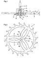
- FIG. 2 illustrates, by way of example in plan, a silicon escapement wheel comprising a serge 5 provided with an escape toothing and three resilient arms or bridges 6 whose central portions 6a define cylindrical portions 7 which at rest are arranged on a cylinder of diameter D7.
- the diameter D7 of the cylindrical passage defined by the cylindrical portions 7 of the arms 6 of the escape wheel 1 is slightly smaller than the diameter D4 of the bearing surface 4 of the axis 2 so that the wheel is driven on the axis by elastic deformation of his arms.
- the tolerances on the diameter D4 of the bearing surface 4 of the axis 2 and on the passage formed by the cylindrical portions 7 of the arms of the wheel 1 are determined so that the forces caused during the installation of the wheel on the axis remain below the elastic limit of silicon.
- the end of the axis 2 comprising the bearing surface 4 still has an intermediate portion 8 of smaller diameter than the diameter D4 of this bearing surface 4 and ends with a pivot 9 for the pivoting of this end of the axis 2 in a bearing.
- the intermediate portion B of the axis 2 is connected to the bearing surface 4 of this axis 2 by a frustoconical chamfer 10.
- the end 9 of this axis 2 is introduced into the cylindrical passage defined by the cylindrical portions 7 of the arms 6 of the escape wheel in order to force the axis in this direction. passage causing the elastic spacing of the arms 6 of the escape wheel 1 and the positioning of the cylindrical portions 7 of said arms against the bearing surface 4 of the axis 2.
- This washer 11 is driven, glued, crimped, welded or fixed in any other way, on the intermediate portion 8 of the axis 2 and keeps the wheel 1 in axial position against the face of the pinion 3.
- the fixing of this washer 11 sure the axis 2 is sufficiently strong to avoid axial, radial or angular relative displacement of the wheel 1 with respect to the axis 2 even under the effect of violent shocks or manipulations assembly of the assembly in a mechanism.
- This washer 11 may also comprise lugs 13 coming for example to lodge against the outer face 14 of the central portions 6a of the elastic arms 6 of the wheel 1, which prevents any relative rotation between the wheel 1 and its axis 2 as well as any transverse displacement of the wheel 1 with respect to this axis 2.
- the fixing device has been described with reference to a silicon wheel provided with three elastic arms. It goes without saying that the wheel could have only two elastic arms provided that the central passage is defined by three points of contact with these arms. One can also consider a wheel with more than three elastic arms. It is also obvious that this same device could be used for the attachment of a rigid radial arm wheel whose hub would be provided with a hole for centering on the intermediate portion 8 of the axis 2 by an introduction to friction of the wheel on this portion of the axis.
- the washer 11 may comprise one or more lugs 12 and these do not cooperate with spokes or arms of the wheel 1, but with corresponding trainings that would include this wheel. In this way any transverse or angular displacement of the wheel relative to the axis is prohibited.
- the assembly device described can be used to fix any piece 1 of silicon on an axis that may not include pinion 3.
- the axis 2 comprises an axial stop, equivalent to the face of the pinion illustrated. against which is axially positioned the wheel 1.
- the diameter of the end portion 26 of the axis 24 corresponds to that of the passage 22 of the ferrule 21 to allow adjustment without play.
- This washer 28 also has a radial projection 30 emerging from one of its faces and intended to cooperate with the slot 23 of the ferrule.
- the washer 2 applies the shell 21 against the stop 27 and the projection 30 cooperating with the slot 23 prevents any angular displacement of the ferrule with respect to the axis 24.
- the silicon balance spring can be fixed to the axis 24 both axially and angularly using the washer 28.
- the washer 28 can be crimped, glued, welded or otherwise fixed to the axis 24.
- the originality of the present device for fixing a silicon part on an axis therefore lies in the fact that the mounting and the positioning of the part on the axis is done with little or no tightening to avoid any deterioration of the silicon part while ensuring correct axial and angular positioning.
Abstract
Description
- La présente invention a pour objet un dispositif de fixation d'une pièce en silicium, notamment d'une roue, planche, pignon ou virole sur un axe. Plus particulièrement le dispositif de fixation concerne la fixation d'une telle pièce en silicium sur un axe en acier. Les pièces en silicium ne peuvent pas être serties ou chassées traditionnellement sur un axe en acier pour assurer leur fixation de façon sûre, le silicium ne se déformant pas plastiquement. Pour obtenir un centrage précis, les roues en silicium peuvent comporter des bras ou parties élastiques définissant des zones d'appui destinées à coopérer avec l'axe. La force élastique due aux bras ou parties élastiques n'est pas toujours suffisante pour assurer la fixation nécessaire de la pièce notamment pour éviter tout déplacement axial ou radial de cette pièce par rapport à l'axe tant au montage du mobile dans un mécanisme que lors de chocs auquel ce mécanisme peut être soumis.
- La présente invention a pour but la réalisation d'un dispositif d'assemblage d'une pièce en silicium sur un axe permettant d'assurer la position tant axiale que radiale de la pièce par rapport à l'axe lors de chocs ou lors des manipulations au montage d'un tel assemblage dans un mécanisme, chocs ou manipulations qui peuvent faire intervenir des efforts axiaux ou radiaux entre l'axe et la pièce supérieurs au couple de fonctionnement normal de cet ensemble,
- Le dispositif de fixation d'une pièce, notamment d'une planche, roue, virole ou pignon en silicium sur un axe en acier permet d'obvier aux inconvénients précités et d'atteindre le but énoncé plus haut et se distingue par les caractéristiques énumérées à la revendication 1 et suivantes.
- Le dessin annexé illustre schématiquement et à titre d'exemple deux formes d'exécution du dispositif de fixation selon l'invention.
- La figure 1 est une vue en coupe axiale de l'ensemble pièce en silicium, ici une roue d'échappement, et de son axe solidarisé à l'aide du dispositif de fixation.
- La figure 2 est une vue en plan de la roue en silicium.
- La figure 3 est une vue en coupe de l'axe.
- La figure 4 est une vue en plan d'une rondelle de fixation.
- La figure 5 est une vue en coupe de la rondelle de fixation illustrée à la figure 4.
- La figure 6 est une vue de dessus de la figure 1.
- La figure 7 illustre vu en coupe l'ensemble spiral en silicium - axe de balancier solidarisé à l'aide du dispositif de fixation.
- La figure 8 illustre vu en plan le spiral en silicium avec sa virole centrale venue d'une pièce.
- La figure 9 est une vue en plan de la rondelle de fixation.
- La figure 10 est une vue en coupe de la rondelle de fixation.
- La forme d'exécution illustrée aux figures 1 à 6 montre plus particulièrement l'assemblage d'une roue d'échappement 1 en silicium sur l'axe 2 d'un pignon de roue d'échappement 3 à l'aide du dispositif selon la présente invention.
- Dans l'exemple illustré l'axe 2 est venu d'une pièce de fabrication avec le pignon 3 de roue d'échappement et est réalisé en acier "Sandvik 20 AP" par exemple, la roue d'échappement 1 étant elle réalisée en silicium comme indiqué ci-dessus.
- D'un côté du pignon 3, l'axe 2 comporte une portée 4 d'un diamètre D4 sur une longueur L.
- La figure 2 illustre à titre d'exemple en plan une roue d'échappement en silicium comportant une serge 5 munie d'une denture d'échappement et trois bras ou ponts élastiques 6 dont les parties centrales 6a définissent des portions cylindriques 7 qui au repos sont disposées sur un cylindre de diamètre D7.
- Le diamètre D7 du passage cylindrique défini par les portions cylindriques 7 des bras 6 de la roue d'échappement 1 est légèrement inférieur au diamètre D4 de la portée 4 de l'axe 2 de manière à ce que la roue soit chassée sur l'axe par déformation élastique de ses bras.
- Les tolérances sur le diamètre D4 de la portée 4 de l'axe 2 et sur le passage formé par les portions cylindriques 7 des bras de la roue 1 sont déterminées pour que les efforts provoqués lors de la mise en place de la roue sur l'axe restent en dessous de la limite élastique du silicium.
- L'extrémité de l'axe 2 comportant la portée 4 présente encore une portion intermédiaire 8 de diamètre plus faible que le diamètre D4 de cette portée 4 et se termine par un pivot 9 pour le pivotement de cette extrémité de l'axe 2 dans un palier. La portion intermédiaire B de l'axe 2 est raccordée à la portée 4 de cet axe 2 par un chanfrein tronconique 10.
- Pour assembler la roue d'échappement 1 à l'axe 2, on introduit l'extrémité 9 de cet axe 2 dans le passage cylindrique défini par les portions cylindriques 7 des bras 6 de la roue d'échappement pour forcer l'axe dans ce passage provoquant l'écartement élastique des bras 6 de la roue d'échappement 1 et le positionnement des portions cylindriques 7 desdits bras contre la portée 4 de l'axe 2.
- Cette fixation par pression élastique des portions cylindriques 7 des bras élastiques 6 de la roue 1 contre la portée 4 de l'axe 2 suffit généralement à assurer un assemblage pouvant supporter le couple de fonctionnement de l'échappement. Toutefois lors du montage de cet ensemble puis lors de l'utilisation d'un mécanisme comportant cet ensemble les chocs et manipulations peuvent provoquer des déplacements axiaux et/ou radiaux entre l'axe 2 et la roue 4, ce qui doit impérativement être évité.
- Pour éviter de tels déplacements intempestifs entre la roue 1 et l'axe 2 le dispositif de fixation comporte une rondelle 11 telle qu'illustrée aux figures 4 et 5. Cette rondelle 11 est réalisée par exemple en Maillechort, laiton ou acier, et comporte un alésage central 12 d'un diamètre D12 plus petit que le diamètre D8 de la portion intermédiaire 8 de l'axe 2 dans le cas où la rondelle est chassée.
- Cette rondelle 11 est chassée, collée, sertie, soudée ou fixée de toute autre façon, sur la portion intermédiaire 8 de l'axe 2 et maintient la roue 1 en position axiale appliquée contre la face du pignon 3. La fixation de cette rondelle 11 sur l'axe 2 est suffisamment résistante pour éviter tout déplacement relatif axial, radial ou angulaire de la roue 1 par rapport à l'axe 2 même sous l'effet de chocs violents ou de manipulations au montage de l'ensemble dans un mécanisme.
- La valeur des diamètres D8 et D2 ainsi que leurs tolérances sont conformes à ce qui se fait habituellement pour assembler une rondelle sur un axe et on obtient une fixation très robuste.
- Cette rondelle 11 peut comporter encore des ergots 13 venant par exemple se loger contre la face externe 14 des parties centrales 6a des bras élastiques 6 de la roue 1, ce qui empêche toute rotation relative entre la roue 1 et son axe 2 de même que tout déplacement transversal de la roue 1 par rapport à cet axe 2.
- On peut envisager d'autres façons d'empêcher toute rotation de la roue 1 sur l'axe 2, en particulier le passage de la roue pourrait présenter une section non circulaire coopérant avec une portion de l'axe ou du pignon qui présenterait une section de forme correspondante. Ainsi, la roue 1 peut être fixée en rotation sur l'axe 2 soit directement par des formes appropriées de ces éléments coopérant ensemble, soit par l'intermédiaire de formations que comporte la rondelle 11 coopérant avec des formations correspondantes de la roue 1.
- Le dispositif de fixation a été décrit en référence à une roue en silicium munie de trois bras élastiques. Il va de soi que la roue pourrait ne comporter que deux bras élastiques pour autant que le passage central soit défini par trois points de contact avec ces bras. On peut également envisager une roue à plus de trois bras élastiques. Il est également évident que ce même dispositif pourrait être utilisé pour la fixation d'une roue à bras radiaux rigides dont le moyeu serait muni d'un trou permettant le centrage sur la portion intermédiaire 8 de l'axe 2 par une mise en place à frottement gras de la roue sur cette portion de l'axe.
- Les bras élastiques de la roue peuvent dans des variantes être remplacés par une partie élastique de la roue assurant le centrage sur l'axe.
- Dans des variantes la rondelle 11 peut comporter un ou plusieurs ergots 12 et ceux-ci coopèrent non pas avec des rayons ou bras de la roue 1, mais avec des formations correspondantes que comporterait cette roue. De cette façon tout déplacement transversal ou angulaire de la roue par rapport à l'axe est interdit.
- Le dispositif d'assemblage décrit peut être utilisé pour fixer n'importe quelle pièce 1 en silicium sur un axe qui pourrait ne pas comporter de pignon 3. Dans ce cas l'axe 2 comporte une butée axiale, équivalent à la face du pignon illustré, contre laquelle vient se positionner axialement la roue 1.
- La seconde forme d'exécution illustrée aux figures 7 à 10 concerne la fixation d'un ressort spiral 20 en silicium comportant une virole 21 venue d'une pièce de fabrication avec le spiral 20. Cette virole 21 comporte un passage 22 et une fente radiale 23.
- Ce spiral en silicium 20 doit être fixé à l'aide du présent dispositif sur un axe 24 sur une partie duquel est chassé un balancier 25. Cet axe 24 comporte une partie terminale 26 de plus petite diamètre qu'un épaulement 27 formant une butée axiale.
- Le diamètre de la partie terminale 26 de l'axe 24 correspond à celui du passage 22 de la virole 21 pour permettre un ajustement sans jeu.
- Le spiral est mis en place par introduction de la partie terminale 26 de l'axe dans le trou 22 de la virole 21 qui vient buter contre l'épaulement 27 de l'axe 24.
- Le dispositif de fixation comporte encore une rondelle 28 comportant un trou 29 d'un diamètre inférieur à celui de la partie terminale 26 de l'axe 24 de manière à pouvoir être chassée sur cette partie terminale 26.
- Cette rondelle 28 comporte encore une saillie radiale 30 émergeant d'une de ses faces et destinée à coopérer avec la fente 23 de la virole.
- Ainsi, en position assemblée, la rondelle 2 applique la virole 21 contre la butée 27 et la saillie 30 coopérant avec la fente 23 empêche tout déplacement angulaire de la virole par rapport à l'axe 24.
- Ainsi, le spiral en silicium peut être fixé à l'axe 24 tant axialement qu'angulairement à l'aide la rondelle 28.
- Dans des variantes la rondelle 28 peut être sertie, collée, soudée ou fixée de toute autre façon à l'axe 24.
- Dans tous les cas, ce dispositif de fixation permet de fixer une pièce en silicium sur un axe sans imposer de contraintes importantes à la pièce en silicium qui pourraient l'endommager tout en assurant sa position axiale et angulaire par rapport à l'axe.
- L'originalité du présent dispositif de fixation d'une pièce en silicium sur un axe réside donc dans le fait que le montage et la mise en place de la pièce sur l'axe se fait avec peu ou pas de serrage pour éviter toute détérioration de la pièce en silicium tout en assurant un positionnement axial et angulaire corrects.
- Le principe revient à réaliser un ajustement libre ou gras entre l'axe et la pièce et de sécuriser la fixation de cet ensemble à l'aide d'une rondelle fixée sur l'axe et servant de butée axiale, radiale et angulaire déterminant les positions relatives de l'axe par rapport à la pièce. En variante, la fixation radiale et angulaire de la pièce 1 sur l'axe 2 se fait par la coopération d'une partie de l'axe 2 avec le passage de la pièce 1, ce passage et cette partie de l'axe 2 présentant des sections circulaires correspondantes.
Claims (10)
- Dispositif de fixation d'une pièce (1;21) notamment d'une planche, roue, pignon ou virole en silicium sur un axe, caractérisé par le fait que l'axe (2;24) présente une butée axiale (3;27), une portée (4;26) jouxtant cette butée; par le fait que la pièce (1;21) comporte un passage coopérant avec la portée (4;26); par le fait qu'il comporte encore une rondelle (11;28) présentant un trou (12;29), cette rondelle (11;28) étant fixée sur l'axe (2;24) de manière à ce que la pièce (1) soit située entre la butée (3 ;27) et la rondelle (11 ;28).
- Dispositif selon la revendication 1, caractérisé par le fait que la rondelle (11;28) est fixée sur l'axe (2) par collage, soudage, sertissage ou chassage.
- Dispositif selon l'une des revendications 1 ou 2, caractérisé par le fait que la rondelle (11;28) comporte encore au moins un ergot (12;30) coopérant avec une formation correspondante (13;23) de la pièce (1;20,21) pour empêcher toute rotation ou translation de cette pièce par rapport à l'axe (2;24).
- Dispositif selon la revendication 1, caractérisé par le fait que la section du passage de la pièce (1;21) est non circulaire et coopère avec une portion de l'axe (2;24) présentant une section de forme correspondante pour empêcher toute rotation ou translation de cette pièce (1;21) par rapport à l'axe (2;24).
- Dispositif selon la revendication 1, caractérisé par le fait que l'axe (2) est l'axe d'un pignon d'échappement et que la pièce (1) est une roue d'échappement.
- Dispositif selon la revendication 4, caractérisé par le fait que la pièce (1) comporte une partie élastique (6) comportant des surfaces (7) permettant le passage d'un axe par déformation de cette partie élastique (6).
- Dispositif selon l'une des revendications précédentes, caractérisé par le fait que l'axe (2) comporte deux portions (4,8), la première (4) jouxtant la butée axiale (3) étant d'un diamètre plus grand que la seconde (8), le diamètre de la première portion (4) correspondant au passage de la pièce en silicium (1) et le diamètre de la seconde (8) correspondant au trou (12) de la rondelle (11).
- Dispositif selon l'une des revendications 1 à 5, caractérisé par le fait que l'axe (24) comporte une portée (26) dont le diamètre correspond au passage (22) de la pièce (20,21) en silicium et au trou (29) de la rondelle (28).
- Dispositif selon l'une des revendications précédentes, caractérisé par le fait que la pièce (20,21) est un ressort spiral en silicium présentant une virole intégrée, soit d'une seule pièce de fabrication avec le spiral.
- Dispositif selon l'une des revendications précédentes, caractérisé par le fait que la pièce (1) est appliquée contre la butée (3 ;27) de l'axe (2 ;24) par la rondelle (11 ;28).
Priority Applications (5)
| Application Number | Priority Date | Filing Date | Title |
|---|---|---|---|
| EP05006186A EP1705533B1 (fr) | 2005-03-22 | 2005-03-22 | Assemblage d'une pièce sur un axe |
| AT05006186T ATE463766T1 (de) | 2005-03-22 | 2005-03-22 | Zusammenbau eines teils mit einer achse |
| DE602005020416T DE602005020416D1 (de) | 2005-03-22 | 2005-03-22 | Zusammenbau eines Teils mit einer Achse |
| EP06003784A EP1708045A3 (fr) | 2005-03-22 | 2006-02-24 | Fixation d' une roue d'horlogerie à un axe |
| HK07102833.0A HK1095643A1 (en) | 2005-03-22 | 2007-03-15 | Assembly of a mechanical part onto an axle |
Applications Claiming Priority (1)
| Application Number | Priority Date | Filing Date | Title |
|---|---|---|---|
| EP05006186A EP1705533B1 (fr) | 2005-03-22 | 2005-03-22 | Assemblage d'une pièce sur un axe |
Publications (2)
| Publication Number | Publication Date |
|---|---|
| EP1705533A1 true EP1705533A1 (fr) | 2006-09-27 |
| EP1705533B1 EP1705533B1 (fr) | 2010-04-07 |
Family
ID=36027101
Family Applications (1)
| Application Number | Title | Priority Date | Filing Date |
|---|---|---|---|
| EP05006186A Not-in-force EP1705533B1 (fr) | 2005-03-22 | 2005-03-22 | Assemblage d'une pièce sur un axe |
Country Status (4)
| Country | Link |
|---|---|
| EP (1) | EP1705533B1 (fr) |
| AT (1) | ATE463766T1 (fr) |
| DE (1) | DE602005020416D1 (fr) |
| HK (1) | HK1095643A1 (fr) |
Cited By (22)
| Publication number | Priority date | Publication date | Assignee | Title |
|---|---|---|---|---|
| EP2107433A1 (fr) | 2008-04-02 | 2009-10-07 | Manufacture et fabrique de montres et chronomètres Ulysse Nardin Le Locle SA | Procédé d'assemblage d'une pièce sur un axe |
| EP2154582A1 (fr) * | 2008-08-15 | 2010-02-17 | Nivarox-FAR S.A. | Procédé d'engrenage pour pièce d'horlogerie |
| EP2219083A1 (fr) | 2009-02-13 | 2010-08-18 | Patek Philippe SA Genève | Composant horloger |
| CH701155B1 (fr) * | 2006-12-27 | 2010-12-15 | Complitime Sa | Oscillateur pour pièce d'horlogerie. |
| EP2273322A1 (fr) | 2009-07-10 | 2011-01-12 | Chopard Technologies SA | Procédé d'assemblage d'une piece sur un organe de pivotement |
| EP2765462A1 (fr) * | 2013-02-12 | 2014-08-13 | ETA SA Manufacture Horlogère Suisse | Roue de centre anti-choc |
| EP2860591A1 (fr) * | 2013-10-09 | 2015-04-15 | Nivarox-FAR S.A. | Système d'assemblage utilisant un élément de blocage élastique conique |
| EP2860592A1 (fr) * | 2013-10-09 | 2015-04-15 | Nivarox-FAR S.A. | Système d'assemblage utilisant un élément de blocage élastique plan |
| JP2016061776A (ja) * | 2014-09-12 | 2016-04-25 | セイコーインスツル株式会社 | 時計用歯車、アンクル、てんぷ、時計用ムーブメント、及び機械式時計 |
| EP3051364A1 (fr) * | 2015-01-29 | 2016-08-03 | Cartier International AG | Système de transmission mécanique par adhérence. |
| EP3106932A1 (fr) * | 2015-06-16 | 2016-12-21 | Nivarox-FAR S.A. | Procédé de fabrication comportant une étape de montage modifiée |
| EP3141520A1 (fr) * | 2015-09-08 | 2017-03-15 | Nivarox-FAR S.A. | Procédé de fabrication d'une pièce micromécanique horlogère et ladite pièce micromécanique horlogère |
| EP3141522A1 (fr) * | 2015-09-08 | 2017-03-15 | Nivarox-FAR S.A. | Pièce micromécanique horlogère comprenant une surface lubrifiée et procédé de réalisation d'une telle pièce micromécanique horlogère |
| JP2017102108A (ja) * | 2015-12-02 | 2017-06-08 | ニヴァロックス−ファー ソシエテ アノニム | 微細機械加工可能な材料製時計部品の保護 |
| RU2655874C2 (ru) * | 2013-01-17 | 2018-05-29 | Омега Са | Деталь часового механизма |
| JP2018155523A (ja) * | 2017-03-16 | 2018-10-04 | セイコーインスツル株式会社 | 時計部品、ムーブメントおよび時計 |
| JP2019052931A (ja) * | 2017-09-14 | 2019-04-04 | セイコーエプソン株式会社 | 時計用部品、時計用ムーブメントおよび時計 |
| JP2020060373A (ja) * | 2018-10-05 | 2020-04-16 | シチズン時計株式会社 | 回転軸と回転部材の固定構造 |
| EP3644128A1 (fr) | 2018-10-24 | 2020-04-29 | Seiko Epson Corporation | Pièce d'horloge et horloge |
| US10761483B2 (en) | 2017-05-16 | 2020-09-01 | Seiko Epson Corporation | Mechanical part, timepiece, and method of manufacturing a mechanical part |
| JP2021001874A (ja) * | 2019-06-21 | 2021-01-07 | ザ・スウォッチ・グループ・リサーチ・アンド・ディベロップメント・リミテッド | ホーンが取り付けられた時計 |
| EP3779608A1 (fr) * | 2019-08-16 | 2021-02-17 | Nivarox-FAR S.A. | Organe de maintien élastique d'un composant d'horlogerie sur un élément de support |
Citations (11)
| Publication number | Priority date | Publication date | Assignee | Title |
|---|---|---|---|---|
| US1037740A (en) * | 1911-04-19 | 1912-09-03 | Hamilton Watch Co | Center wheel for watches. |
| FR1310271A (fr) * | 1961-01-12 | 1963-03-06 | The United States Time Corporation | Arbre rotatif d'un mouvement d'horlogerie |
| GB1115204A (en) * | 1964-07-15 | 1968-05-29 | Junghans Gmbh Geb | Improvements in or relating to electric clock movements |
| US3408809A (en) * | 1965-04-21 | 1968-11-05 | Dumont Marcel | Device for securing a balance spring to a balance staff |
| US3695033A (en) * | 1970-06-09 | 1972-10-03 | Suwa Seikosha Kk | Controlling device for an escape wheel |
| EP0851295A1 (fr) * | 1996-12-27 | 1998-07-01 | Ecole Polytechnique Federale De Lausanne | Procédé de fabrication de microstructures par conformation multicouche d'une résine photosensible et microstructures ainsi obtenues |
| US6025062A (en) * | 1997-03-24 | 2000-02-15 | Deutsches Zentrum Fur Luft-Und Raumfahrt E.V. | Cogged component for the mechanical transmission of force |
| US6307815B1 (en) * | 1998-07-23 | 2001-10-23 | Sandia Corporation | Microelectromechanical timer |
| EP1233314A1 (fr) * | 2001-02-15 | 2002-08-21 | DAMASKO, Konrad | Mouvement d'horlogerie |
| EP1445670A1 (fr) * | 2003-02-06 | 2004-08-11 | ETA SA Manufacture Horlogère Suisse | Spiral de résonateur balancier-spiral et son procédé de fabrication |
| EP1513029A1 (fr) * | 2003-09-02 | 2005-03-09 | Patek Philippe Sa | Virole d'horlogerie |
-
2005
- 2005-03-22 DE DE602005020416T patent/DE602005020416D1/de active Active
- 2005-03-22 EP EP05006186A patent/EP1705533B1/fr not_active Not-in-force
- 2005-03-22 AT AT05006186T patent/ATE463766T1/de not_active IP Right Cessation
-
2007
- 2007-03-15 HK HK07102833.0A patent/HK1095643A1/xx not_active IP Right Cessation
Patent Citations (11)
| Publication number | Priority date | Publication date | Assignee | Title |
|---|---|---|---|---|
| US1037740A (en) * | 1911-04-19 | 1912-09-03 | Hamilton Watch Co | Center wheel for watches. |
| FR1310271A (fr) * | 1961-01-12 | 1963-03-06 | The United States Time Corporation | Arbre rotatif d'un mouvement d'horlogerie |
| GB1115204A (en) * | 1964-07-15 | 1968-05-29 | Junghans Gmbh Geb | Improvements in or relating to electric clock movements |
| US3408809A (en) * | 1965-04-21 | 1968-11-05 | Dumont Marcel | Device for securing a balance spring to a balance staff |
| US3695033A (en) * | 1970-06-09 | 1972-10-03 | Suwa Seikosha Kk | Controlling device for an escape wheel |
| EP0851295A1 (fr) * | 1996-12-27 | 1998-07-01 | Ecole Polytechnique Federale De Lausanne | Procédé de fabrication de microstructures par conformation multicouche d'une résine photosensible et microstructures ainsi obtenues |
| US6025062A (en) * | 1997-03-24 | 2000-02-15 | Deutsches Zentrum Fur Luft-Und Raumfahrt E.V. | Cogged component for the mechanical transmission of force |
| US6307815B1 (en) * | 1998-07-23 | 2001-10-23 | Sandia Corporation | Microelectromechanical timer |
| EP1233314A1 (fr) * | 2001-02-15 | 2002-08-21 | DAMASKO, Konrad | Mouvement d'horlogerie |
| EP1445670A1 (fr) * | 2003-02-06 | 2004-08-11 | ETA SA Manufacture Horlogère Suisse | Spiral de résonateur balancier-spiral et son procédé de fabrication |
| EP1513029A1 (fr) * | 2003-09-02 | 2005-03-09 | Patek Philippe Sa | Virole d'horlogerie |
Cited By (50)
| Publication number | Priority date | Publication date | Assignee | Title |
|---|---|---|---|---|
| CH701155B1 (fr) * | 2006-12-27 | 2010-12-15 | Complitime Sa | Oscillateur pour pièce d'horlogerie. |
| EP2107433A1 (fr) | 2008-04-02 | 2009-10-07 | Manufacture et fabrique de montres et chronomètres Ulysse Nardin Le Locle SA | Procédé d'assemblage d'une pièce sur un axe |
| US9310770B2 (en) | 2008-08-15 | 2016-04-12 | Nivarox-Far S.A. | Gear system for a timepiece |
| EP2154582A1 (fr) * | 2008-08-15 | 2010-02-17 | Nivarox-FAR S.A. | Procédé d'engrenage pour pièce d'horlogerie |
| WO2010018051A1 (fr) * | 2008-08-15 | 2010-02-18 | Nivarox-Far S.A. | Système d'engrenage pour une pièce d'horlogerie |
| CN102124415B (zh) * | 2008-08-15 | 2012-12-19 | 尼瓦洛克斯-法尔股份有限公司 | 钟表的齿轮系统 |
| RU2498383C2 (ru) * | 2008-08-15 | 2013-11-10 | Ниварокс-Фар С.А. | Система шестерен для часов |
| EP2219083A1 (fr) | 2009-02-13 | 2010-08-18 | Patek Philippe SA Genève | Composant horloger |
| EP2273322A1 (fr) | 2009-07-10 | 2011-01-12 | Chopard Technologies SA | Procédé d'assemblage d'une piece sur un organe de pivotement |
| CN101968626A (zh) * | 2009-07-10 | 2011-02-09 | 萧邦科技公司 | 用于将零件装配在枢转机件上的方法 |
| CN101968626B (zh) * | 2009-07-10 | 2014-11-19 | 萧邦科技公司 | 用于将零件装配在枢转机件上的方法 |
| RU2655874C2 (ru) * | 2013-01-17 | 2018-05-29 | Омега Са | Деталь часового механизма |
| US9244432B2 (en) | 2013-02-12 | 2016-01-26 | Eta Sa Manufacture Horlogère Suisse | Shockproof centre wheel |
| CN103984219A (zh) * | 2013-02-12 | 2014-08-13 | Eta瑞士钟表制造股份有限公司 | 防震中心轮 |
| EP2765462A1 (fr) * | 2013-02-12 | 2014-08-13 | ETA SA Manufacture Horlogère Suisse | Roue de centre anti-choc |
| CN107885073A (zh) * | 2013-02-12 | 2018-04-06 | Eta瑞士钟表制造股份有限公司 | 防震钟表轮 |
| CN103984219B (zh) * | 2013-02-12 | 2017-09-26 | Eta瑞士钟表制造股份有限公司 | 防震钟表轮 |
| CN106919038A (zh) * | 2013-02-12 | 2017-07-04 | Eta瑞士钟表制造股份有限公司 | 防震中心轮 |
| CN106919038B (zh) * | 2013-02-12 | 2019-04-02 | Eta瑞士钟表制造股份有限公司 | 防震中心轮 |
| RU2589615C2 (ru) * | 2013-10-09 | 2016-07-10 | Ниварокс-Фар С.А. | Узел, в котором используется конический упругий стопорный элемент |
| US9488961B2 (en) | 2013-10-09 | 2016-11-08 | Nivarox-Far S.A. | Assembly system utilising a conical, elastic locking element |
| US9671755B2 (en) | 2013-10-09 | 2017-06-06 | Nivarox-Far S.A. | Assembly system utilizing a flat, elastic locking element |
| EP2860592A1 (fr) * | 2013-10-09 | 2015-04-15 | Nivarox-FAR S.A. | Système d'assemblage utilisant un élément de blocage élastique plan |
| CN104570684B (zh) * | 2013-10-09 | 2017-08-08 | 尼瓦洛克斯-法尔股份有限公司 | 利用平的弹性锁定件的组件系统 |
| EP2860591A1 (fr) * | 2013-10-09 | 2015-04-15 | Nivarox-FAR S.A. | Système d'assemblage utilisant un élément de blocage élastique conique |
| RU2679451C2 (ru) * | 2013-10-09 | 2019-02-11 | Ниварокс-Фар С.А. | Сборочный узел, использующий плоский, упругий фиксирующий элемент |
| JP2016061776A (ja) * | 2014-09-12 | 2016-04-25 | セイコーインスツル株式会社 | 時計用歯車、アンクル、てんぷ、時計用ムーブメント、及び機械式時計 |
| EP3051364A1 (fr) * | 2015-01-29 | 2016-08-03 | Cartier International AG | Système de transmission mécanique par adhérence. |
| EP3106932A1 (fr) * | 2015-06-16 | 2016-12-21 | Nivarox-FAR S.A. | Procédé de fabrication comportant une étape de montage modifiée |
| EP3112952A1 (fr) * | 2015-06-16 | 2017-01-04 | Nivarox-FAR S.A. | Procede de fabrication comportant une etape de montage modifiee |
| US10343234B2 (en) | 2015-06-16 | 2019-07-09 | Nivarox-Far S.A. | Fabrication method including a modified assembly step |
| EP3141522A1 (fr) * | 2015-09-08 | 2017-03-15 | Nivarox-FAR S.A. | Pièce micromécanique horlogère comprenant une surface lubrifiée et procédé de réalisation d'une telle pièce micromécanique horlogère |
| US10281879B2 (en) | 2015-09-08 | 2019-05-07 | Nivarox-Far S.A. | Micromechanical timepiece part comprising a lubricated surface and method for producing such a micromechanical timepiece part |
| EP3141520A1 (fr) * | 2015-09-08 | 2017-03-15 | Nivarox-FAR S.A. | Procédé de fabrication d'une pièce micromécanique horlogère et ladite pièce micromécanique horlogère |
| US11378918B2 (en) | 2015-09-08 | 2022-07-05 | Nivarox-Far S.A. | Method for manufacturing a micromechanical timepiece part and said micromechanical timepiece part |
| JP2017102108A (ja) * | 2015-12-02 | 2017-06-08 | ニヴァロックス−ファー ソシエテ アノニム | 微細機械加工可能な材料製時計部品の保護 |
| JP2018155523A (ja) * | 2017-03-16 | 2018-10-04 | セイコーインスツル株式会社 | 時計部品、ムーブメントおよび時計 |
| US10761483B2 (en) | 2017-05-16 | 2020-09-01 | Seiko Epson Corporation | Mechanical part, timepiece, and method of manufacturing a mechanical part |
| JP7006065B2 (ja) | 2017-09-14 | 2022-01-24 | セイコーエプソン株式会社 | 時計用部品、時計用ムーブメントおよび時計 |
| JP2019052931A (ja) * | 2017-09-14 | 2019-04-04 | セイコーエプソン株式会社 | 時計用部品、時計用ムーブメントおよび時計 |
| JP7055085B2 (ja) | 2018-10-05 | 2022-04-15 | シチズン時計株式会社 | 回転軸と回転部材の固定構造 |
| JP2020060373A (ja) * | 2018-10-05 | 2020-04-16 | シチズン時計株式会社 | 回転軸と回転部材の固定構造 |
| EP3644128A1 (fr) | 2018-10-24 | 2020-04-29 | Seiko Epson Corporation | Pièce d'horloge et horloge |
| US11409244B2 (en) | 2018-10-24 | 2022-08-09 | Seiko Epson Corporation | Timepiece part and timepiece |
| US20220299941A1 (en) * | 2018-10-24 | 2022-09-22 | Seiko Epson Corporation | Timepiece Part and Timepiece |
| US11829108B2 (en) * | 2018-10-24 | 2023-11-28 | Seiko Epson Corporation | Timepiece part and timepiece |
| JP2021001874A (ja) * | 2019-06-21 | 2021-01-07 | ザ・スウォッチ・グループ・リサーチ・アンド・ディベロップメント・リミテッド | ホーンが取り付けられた時計 |
| EP3779608A1 (fr) * | 2019-08-16 | 2021-02-17 | Nivarox-FAR S.A. | Organe de maintien élastique d'un composant d'horlogerie sur un élément de support |
| CN112394627A (zh) * | 2019-08-16 | 2021-02-23 | 尼瓦罗克斯-法尔股份公司 | 用于在支撑元件上弹性地保持时计部件的机件 |
| US11573533B2 (en) | 2019-08-16 | 2023-02-07 | Nivarox-Far S.A. | Organ for elastically holding a timepiece component on a support element |
Also Published As
| Publication number | Publication date |
|---|---|
| EP1705533B1 (fr) | 2010-04-07 |
| ATE463766T1 (de) | 2010-04-15 |
| DE602005020416D1 (de) | 2010-05-20 |
| HK1095643A1 (en) | 2007-05-11 |
Similar Documents
| Publication | Publication Date | Title |
|---|---|---|
| EP1705533B1 (fr) | Assemblage d'une pièce sur un axe | |
| EP1857892B1 (fr) | Montre à élément tournant | |
| EP1927037B1 (fr) | Dispositif de fixation d'un fond sur une carrure d'une montre | |
| EP2743781B1 (fr) | Dispositif d'assemblage par verrouillage d'un emboîtement | |
| WO2007099068A1 (fr) | Piece de micro-mecanique avec ouverture de forme pour assemblage sur un axe | |
| FR2796007A1 (fr) | Dispositif stabilisateur pour un vehicule automobile | |
| EP2560055B1 (fr) | Préréglage d'ébat de mobile horloger | |
| EP2482144B1 (fr) | Système d'assemblage par blocage à cliquet | |
| CH703935A2 (fr) | Organe régulateur balancier-spiral. | |
| CH698677B1 (fr) | Ensemble comportant un axe et une pièce en silicium fixée audit axe. | |
| EP1637940B1 (fr) | Virole d'horlogerie | |
| EP2107433B1 (fr) | Procédé d'assemblage d'une pièce sur un axe | |
| EP1923754B1 (fr) | Mouvement d'horlogerie équipé d'un module d'affichage | |
| CH701075B1 (fr) | Ensemble formé d'une roue et de son axe et roue pour un tel ensemble. | |
| FR2798099A1 (fr) | Siege de vehicule dote d'un mecanisme d'articulation | |
| CH703961A2 (fr) | Méthode d'assemblage d'une pièce en matériau dur sur un axe et ensemble comprenant une telle pièce assemblée sur un axe. | |
| EP0699280A1 (fr) | Frein a disque a etrier coulissant | |
| FR2902395A1 (fr) | Kit de montage d'une pedale de frein a un pedalier equipant un vehicule automobile, pedale de frein, et procede de raccordement | |
| EP3422117B1 (fr) | Palier amortisseur de choc pour un axe d'un mobile d'une pièce d horlogerie | |
| EP0634313A1 (fr) | Corps de colonne de direction pour véhicule automobile | |
| CH712197B1 (fr) | Système à friction pour mouvement d'horlogerie et son procédé d'assemblage. | |
| CH508914A (fr) | Dispositif de fixation de l'extrémité intérieure d'un spiral | |
| FR2833028A1 (fr) | Assemblage a emboitement pour echafaudages | |
| CH707341A2 (fr) | Dispositif d'assemblage par verrouillage d'un emboîtement et pièce d'horlogerie comportant un tel dispositif. | |
| EP4280002A1 (fr) | Module chronographe muni d'une roue amovible |
Legal Events
| Date | Code | Title | Description |
|---|---|---|---|
| PUAI | Public reference made under article 153(3) epc to a published international application that has entered the european phase |
Free format text: ORIGINAL CODE: 0009012 |
|
| AK | Designated contracting states |
Kind code of ref document: A1 Designated state(s): AT BE BG CH CY CZ DE DK EE ES FI FR GB GR HU IE IS IT LI LT LU MC NL PL PT RO SE SI SK TR |
|
| AX | Request for extension of the european patent |
Extension state: AL BA HR LV MK YU |
|
| 17P | Request for examination filed |
Effective date: 20070131 |
|
| R17P | Request for examination filed (corrected) |
Effective date: 20070124 |
|
| REG | Reference to a national code |
Ref country code: HK Ref legal event code: DE Ref document number: 1095643 Country of ref document: HK |
|
| AKX | Designation fees paid |
Designated state(s): AT BE BG CH CY CZ DE DK EE ES FI FR GB GR HU IE IS IT LI LT LU MC NL PL PT RO SE SI SK TR |
|
| 17Q | First examination report despatched |
Effective date: 20070131 |
|
| RAP1 | Party data changed (applicant data changed or rights of an application transferred) |
Owner name: PATEK, PHILIPPE SA |
|
| GRAP | Despatch of communication of intention to grant a patent |
Free format text: ORIGINAL CODE: EPIDOSNIGR1 |
|
| GRAS | Grant fee paid |
Free format text: ORIGINAL CODE: EPIDOSNIGR3 |
|
| RAP1 | Party data changed (applicant data changed or rights of an application transferred) |
Owner name: PATEK PHILIPPE SA GENEVE |
|
| GRAA | (expected) grant |
Free format text: ORIGINAL CODE: 0009210 |
|
| AK | Designated contracting states |
Kind code of ref document: B1 Designated state(s): AT BE BG CH CY CZ DE DK EE ES FI FR GB GR HU IE IS IT LI LT LU MC NL PL PT RO SE SI SK TR |
|
| REG | Reference to a national code |
Ref country code: GB Ref legal event code: FG4D Free format text: NOT ENGLISH |
|
| REG | Reference to a national code |
Ref country code: CH Ref legal event code: EP Ref country code: CH Ref legal event code: NV Representative=s name: MICHELI & CIE SA |
|
| REG | Reference to a national code |
Ref country code: IE Ref legal event code: FG4D Free format text: LANGUAGE OF EP DOCUMENT: FRENCH |
|
| REF | Corresponds to: |
Ref document number: 602005020416 Country of ref document: DE Date of ref document: 20100520 Kind code of ref document: P |
|
| REG | Reference to a national code |
Ref country code: HK Ref legal event code: GR Ref document number: 1095643 Country of ref document: HK |
|
| REG | Reference to a national code |
Ref country code: NL Ref legal event code: VDEP Effective date: 20100407 |
|
| PG25 | Lapsed in a contracting state [announced via postgrant information from national office to epo] |
Ref country code: SI Free format text: LAPSE BECAUSE OF FAILURE TO SUBMIT A TRANSLATION OF THE DESCRIPTION OR TO PAY THE FEE WITHIN THE PRESCRIBED TIME-LIMIT Effective date: 20100407 |
|
| LTIE | Lt: invalidation of european patent or patent extension |
Effective date: 20100407 |
|
| REG | Reference to a national code |
Ref country code: IE Ref legal event code: FD4D |
|
| PG25 | Lapsed in a contracting state [announced via postgrant information from national office to epo] |
Ref country code: LT Free format text: LAPSE BECAUSE OF FAILURE TO SUBMIT A TRANSLATION OF THE DESCRIPTION OR TO PAY THE FEE WITHIN THE PRESCRIBED TIME-LIMIT Effective date: 20100407 Ref country code: ES Free format text: LAPSE BECAUSE OF FAILURE TO SUBMIT A TRANSLATION OF THE DESCRIPTION OR TO PAY THE FEE WITHIN THE PRESCRIBED TIME-LIMIT Effective date: 20100718 Ref country code: NL Free format text: LAPSE BECAUSE OF FAILURE TO SUBMIT A TRANSLATION OF THE DESCRIPTION OR TO PAY THE FEE WITHIN THE PRESCRIBED TIME-LIMIT Effective date: 20100407 Ref country code: SE Free format text: LAPSE BECAUSE OF FAILURE TO SUBMIT A TRANSLATION OF THE DESCRIPTION OR TO PAY THE FEE WITHIN THE PRESCRIBED TIME-LIMIT Effective date: 20100407 |
|
| PG25 | Lapsed in a contracting state [announced via postgrant information from national office to epo] |
Ref country code: AT Free format text: LAPSE BECAUSE OF FAILURE TO SUBMIT A TRANSLATION OF THE DESCRIPTION OR TO PAY THE FEE WITHIN THE PRESCRIBED TIME-LIMIT Effective date: 20100407 Ref country code: FI Free format text: LAPSE BECAUSE OF FAILURE TO SUBMIT A TRANSLATION OF THE DESCRIPTION OR TO PAY THE FEE WITHIN THE PRESCRIBED TIME-LIMIT Effective date: 20100407 Ref country code: IS Free format text: LAPSE BECAUSE OF FAILURE TO SUBMIT A TRANSLATION OF THE DESCRIPTION OR TO PAY THE FEE WITHIN THE PRESCRIBED TIME-LIMIT Effective date: 20100807 |
|
| PG25 | Lapsed in a contracting state [announced via postgrant information from national office to epo] |
Ref country code: GR Free format text: LAPSE BECAUSE OF FAILURE TO SUBMIT A TRANSLATION OF THE DESCRIPTION OR TO PAY THE FEE WITHIN THE PRESCRIBED TIME-LIMIT Effective date: 20100708 Ref country code: CY Free format text: LAPSE BECAUSE OF FAILURE TO SUBMIT A TRANSLATION OF THE DESCRIPTION OR TO PAY THE FEE WITHIN THE PRESCRIBED TIME-LIMIT Effective date: 20100505 Ref country code: PL Free format text: LAPSE BECAUSE OF FAILURE TO SUBMIT A TRANSLATION OF THE DESCRIPTION OR TO PAY THE FEE WITHIN THE PRESCRIBED TIME-LIMIT Effective date: 20100407 |
|
| PG25 | Lapsed in a contracting state [announced via postgrant information from national office to epo] |
Ref country code: EE Free format text: LAPSE BECAUSE OF FAILURE TO SUBMIT A TRANSLATION OF THE DESCRIPTION OR TO PAY THE FEE WITHIN THE PRESCRIBED TIME-LIMIT Effective date: 20100407 Ref country code: PT Free format text: LAPSE BECAUSE OF FAILURE TO SUBMIT A TRANSLATION OF THE DESCRIPTION OR TO PAY THE FEE WITHIN THE PRESCRIBED TIME-LIMIT Effective date: 20100809 Ref country code: IE Free format text: LAPSE BECAUSE OF FAILURE TO SUBMIT A TRANSLATION OF THE DESCRIPTION OR TO PAY THE FEE WITHIN THE PRESCRIBED TIME-LIMIT Effective date: 20100407 Ref country code: DK Free format text: LAPSE BECAUSE OF FAILURE TO SUBMIT A TRANSLATION OF THE DESCRIPTION OR TO PAY THE FEE WITHIN THE PRESCRIBED TIME-LIMIT Effective date: 20100407 |
|
| PLBE | No opposition filed within time limit |
Free format text: ORIGINAL CODE: 0009261 |
|
| STAA | Information on the status of an ep patent application or granted ep patent |
Free format text: STATUS: NO OPPOSITION FILED WITHIN TIME LIMIT |
|
| PG25 | Lapsed in a contracting state [announced via postgrant information from national office to epo] |
Ref country code: CZ Free format text: LAPSE BECAUSE OF FAILURE TO SUBMIT A TRANSLATION OF THE DESCRIPTION OR TO PAY THE FEE WITHIN THE PRESCRIBED TIME-LIMIT Effective date: 20100407 Ref country code: SK Free format text: LAPSE BECAUSE OF FAILURE TO SUBMIT A TRANSLATION OF THE DESCRIPTION OR TO PAY THE FEE WITHIN THE PRESCRIBED TIME-LIMIT Effective date: 20100407 Ref country code: RO Free format text: LAPSE BECAUSE OF FAILURE TO SUBMIT A TRANSLATION OF THE DESCRIPTION OR TO PAY THE FEE WITHIN THE PRESCRIBED TIME-LIMIT Effective date: 20100407 |
|
| 26N | No opposition filed |
Effective date: 20110110 |
|
| PG25 | Lapsed in a contracting state [announced via postgrant information from national office to epo] |
Ref country code: IT Free format text: LAPSE BECAUSE OF FAILURE TO SUBMIT A TRANSLATION OF THE DESCRIPTION OR TO PAY THE FEE WITHIN THE PRESCRIBED TIME-LIMIT Effective date: 20100407 |
|
| BERE | Be: lapsed |
Owner name: PATEK PHILIPPE SA GENEVE Effective date: 20110331 |
|
| PG25 | Lapsed in a contracting state [announced via postgrant information from national office to epo] |
Ref country code: MC Free format text: LAPSE BECAUSE OF NON-PAYMENT OF DUE FEES Effective date: 20110331 |
|
| REG | Reference to a national code |
Ref country code: CH Ref legal event code: PL |
|
| GBPC | Gb: european patent ceased through non-payment of renewal fee |
Effective date: 20110322 |
|
| REG | Reference to a national code |
Ref country code: FR Ref legal event code: ST Effective date: 20111130 |
|
| PG25 | Lapsed in a contracting state [announced via postgrant information from national office to epo] |
Ref country code: BE Free format text: LAPSE BECAUSE OF NON-PAYMENT OF DUE FEES Effective date: 20110331 |
|
| PG25 | Lapsed in a contracting state [announced via postgrant information from national office to epo] |
Ref country code: LI Free format text: LAPSE BECAUSE OF NON-PAYMENT OF DUE FEES Effective date: 20110331 Ref country code: FR Free format text: LAPSE BECAUSE OF NON-PAYMENT OF DUE FEES Effective date: 20110331 Ref country code: CH Free format text: LAPSE BECAUSE OF NON-PAYMENT OF DUE FEES Effective date: 20110331 Ref country code: DE Free format text: LAPSE BECAUSE OF NON-PAYMENT OF DUE FEES Effective date: 20111001 |
|
| PG25 | Lapsed in a contracting state [announced via postgrant information from national office to epo] |
Ref country code: GB Free format text: LAPSE BECAUSE OF NON-PAYMENT OF DUE FEES Effective date: 20110322 |
|
| REG | Reference to a national code |
Ref country code: DE Ref legal event code: R119 Ref document number: 602005020416 Country of ref document: DE Effective date: 20111001 |
|
| PG25 | Lapsed in a contracting state [announced via postgrant information from national office to epo] |
Ref country code: LU Free format text: LAPSE BECAUSE OF NON-PAYMENT OF DUE FEES Effective date: 20110322 |
|
| PG25 | Lapsed in a contracting state [announced via postgrant information from national office to epo] |
Ref country code: TR Free format text: LAPSE BECAUSE OF FAILURE TO SUBMIT A TRANSLATION OF THE DESCRIPTION OR TO PAY THE FEE WITHIN THE PRESCRIBED TIME-LIMIT Effective date: 20100407 Ref country code: BG Free format text: LAPSE BECAUSE OF FAILURE TO SUBMIT A TRANSLATION OF THE DESCRIPTION OR TO PAY THE FEE WITHIN THE PRESCRIBED TIME-LIMIT Effective date: 20100707 |
|
| PG25 | Lapsed in a contracting state [announced via postgrant information from national office to epo] |
Ref country code: HU Free format text: LAPSE BECAUSE OF FAILURE TO SUBMIT A TRANSLATION OF THE DESCRIPTION OR TO PAY THE FEE WITHIN THE PRESCRIBED TIME-LIMIT Effective date: 20100407 |