EP1704703B1 - Appareil a configuration variable - Google Patents
Appareil a configuration variable Download PDFInfo
- Publication number
- EP1704703B1 EP1704703B1 EP05701890.5A EP05701890A EP1704703B1 EP 1704703 B1 EP1704703 B1 EP 1704703B1 EP 05701890 A EP05701890 A EP 05701890A EP 1704703 B1 EP1704703 B1 EP 1704703B1
- Authority
- EP
- European Patent Office
- Prior art keywords
- components
- conductive plate
- coupling
- mechanical coupling
- signal
- Prior art date
- Legal status (The legal status is an assumption and is not a legal conclusion. Google has not performed a legal analysis and makes no representation as to the accuracy of the status listed.)
- Not-in-force
Links
- 230000008878 coupling Effects 0.000 claims description 228
- 238000010168 coupling process Methods 0.000 claims description 228
- 238000005859 coupling reaction Methods 0.000 claims description 228
- 230000001939 inductive effect Effects 0.000 claims description 19
- 238000000429 assembly Methods 0.000 claims description 7
- 238000000034 method Methods 0.000 claims description 6
- 238000012546 transfer Methods 0.000 description 16
- 238000004891 communication Methods 0.000 description 14
- 239000000463 material Substances 0.000 description 8
- 238000010586 diagram Methods 0.000 description 6
- 230000007246 mechanism Effects 0.000 description 5
- 230000005540 biological transmission Effects 0.000 description 4
- -1 polyethylene Polymers 0.000 description 4
- 229920001343 polytetrafluoroethylene Polymers 0.000 description 4
- 230000000712 assembly Effects 0.000 description 3
- 239000003990 capacitor Substances 0.000 description 3
- 238000006073 displacement reaction Methods 0.000 description 3
- 238000012360 testing method Methods 0.000 description 3
- 239000004698 Polyethylene Substances 0.000 description 2
- 230000001413 cellular effect Effects 0.000 description 2
- 239000000919 ceramic Substances 0.000 description 2
- 238000000576 coating method Methods 0.000 description 2
- 230000000295 complement effect Effects 0.000 description 2
- 239000013078 crystal Substances 0.000 description 2
- 238000001514 detection method Methods 0.000 description 2
- 230000005674 electromagnetic induction Effects 0.000 description 2
- 238000002955 isolation Methods 0.000 description 2
- 239000004973 liquid crystal related substance Substances 0.000 description 2
- 230000002093 peripheral effect Effects 0.000 description 2
- 239000004033 plastic Substances 0.000 description 2
- 229920003023 plastic Polymers 0.000 description 2
- 229920000573 polyethylene Polymers 0.000 description 2
- 230000001681 protective effect Effects 0.000 description 2
- 238000006243 chemical reaction Methods 0.000 description 1
- 238000013500 data storage Methods 0.000 description 1
- 230000001419 dependent effect Effects 0.000 description 1
- 238000009795 derivation Methods 0.000 description 1
- 230000000694 effects Effects 0.000 description 1
- 238000005516 engineering process Methods 0.000 description 1
- 210000003195 fascia Anatomy 0.000 description 1
- 238000010348 incorporation Methods 0.000 description 1
- 238000004519 manufacturing process Methods 0.000 description 1
- 238000001465 metallisation Methods 0.000 description 1
- 238000012545 processing Methods 0.000 description 1
- 238000000926 separation method Methods 0.000 description 1
Images


Classifications
-
- H—ELECTRICITY
- H04—ELECTRIC COMMUNICATION TECHNIQUE
- H04M—TELEPHONIC COMMUNICATION
- H04M1/00—Substation equipment, e.g. for use by subscribers
- H04M1/02—Constructional features of telephone sets
- H04M1/0202—Portable telephone sets, e.g. cordless phones, mobile phones or bar type handsets
- H04M1/0206—Portable telephones comprising a plurality of mechanically joined movable body parts, e.g. hinged housings
- H04M1/0208—Portable telephones comprising a plurality of mechanically joined movable body parts, e.g. hinged housings characterized by the relative motions of the body parts
- H04M1/0214—Foldable telephones, i.e. with body parts pivoting to an open position around an axis parallel to the plane they define in closed position
- H04M1/0216—Foldable in one direction, i.e. using a one degree of freedom hinge
-
- G—PHYSICS
- G06—COMPUTING; CALCULATING OR COUNTING
- G06F—ELECTRIC DIGITAL DATA PROCESSING
- G06F1/00—Details not covered by groups G06F3/00 - G06F13/00 and G06F21/00
- G06F1/16—Constructional details or arrangements
- G06F1/1613—Constructional details or arrangements for portable computers
- G06F1/1615—Constructional details or arrangements for portable computers with several enclosures having relative motions, each enclosure supporting at least one I/O or computing function
- G06F1/1616—Constructional details or arrangements for portable computers with several enclosures having relative motions, each enclosure supporting at least one I/O or computing function with folding flat displays, e.g. laptop computers or notebooks having a clamshell configuration, with body parts pivoting to an open position around an axis parallel to the plane they define in closed position
-
- G—PHYSICS
- G06—COMPUTING; CALCULATING OR COUNTING
- G06F—ELECTRIC DIGITAL DATA PROCESSING
- G06F1/00—Details not covered by groups G06F3/00 - G06F13/00 and G06F21/00
- G06F1/16—Constructional details or arrangements
- G06F1/1613—Constructional details or arrangements for portable computers
- G06F1/1615—Constructional details or arrangements for portable computers with several enclosures having relative motions, each enclosure supporting at least one I/O or computing function
- G06F1/1624—Constructional details or arrangements for portable computers with several enclosures having relative motions, each enclosure supporting at least one I/O or computing function with sliding enclosures, e.g. sliding keyboard or display
-
- G—PHYSICS
- G06—COMPUTING; CALCULATING OR COUNTING
- G06F—ELECTRIC DIGITAL DATA PROCESSING
- G06F1/00—Details not covered by groups G06F3/00 - G06F13/00 and G06F21/00
- G06F1/16—Constructional details or arrangements
- G06F1/1613—Constructional details or arrangements for portable computers
- G06F1/1633—Constructional details or arrangements of portable computers not specific to the type of enclosures covered by groups G06F1/1615 - G06F1/1626
- G06F1/1675—Miscellaneous details related to the relative movement between the different enclosures or enclosure parts
- G06F1/1677—Miscellaneous details related to the relative movement between the different enclosures or enclosure parts for detecting open or closed state or particular intermediate positions assumed by movable parts of the enclosure, e.g. detection of display lid position with respect to main body in a laptop, detection of opening of the cover of battery compartment
-
- G—PHYSICS
- G06—COMPUTING; CALCULATING OR COUNTING
- G06F—ELECTRIC DIGITAL DATA PROCESSING
- G06F1/00—Details not covered by groups G06F3/00 - G06F13/00 and G06F21/00
- G06F1/16—Constructional details or arrangements
- G06F1/1613—Constructional details or arrangements for portable computers
- G06F1/1633—Constructional details or arrangements of portable computers not specific to the type of enclosures covered by groups G06F1/1615 - G06F1/1626
- G06F1/1675—Miscellaneous details related to the relative movement between the different enclosures or enclosure parts
- G06F1/1679—Miscellaneous details related to the relative movement between the different enclosures or enclosure parts for locking or maintaining the movable parts of the enclosure in a fixed position, e.g. latching mechanism at the edge of the display in a laptop or for the screen protective cover of a PDA
-
- G—PHYSICS
- G06—COMPUTING; CALCULATING OR COUNTING
- G06F—ELECTRIC DIGITAL DATA PROCESSING
- G06F1/00—Details not covered by groups G06F3/00 - G06F13/00 and G06F21/00
- G06F1/16—Constructional details or arrangements
- G06F1/1613—Constructional details or arrangements for portable computers
- G06F1/1633—Constructional details or arrangements of portable computers not specific to the type of enclosures covered by groups G06F1/1615 - G06F1/1626
- G06F1/1675—Miscellaneous details related to the relative movement between the different enclosures or enclosure parts
- G06F1/1681—Details related solely to hinges
-
- G—PHYSICS
- G06—COMPUTING; CALCULATING OR COUNTING
- G06F—ELECTRIC DIGITAL DATA PROCESSING
- G06F1/00—Details not covered by groups G06F3/00 - G06F13/00 and G06F21/00
- G06F1/16—Constructional details or arrangements
- G06F1/1613—Constructional details or arrangements for portable computers
- G06F1/1633—Constructional details or arrangements of portable computers not specific to the type of enclosures covered by groups G06F1/1615 - G06F1/1626
- G06F1/1675—Miscellaneous details related to the relative movement between the different enclosures or enclosure parts
- G06F1/1683—Miscellaneous details related to the relative movement between the different enclosures or enclosure parts for the transmission of signal or power between the different housings, e.g. details of wired or wireless communication, passage of cabling
-
- H—ELECTRICITY
- H04—ELECTRIC COMMUNICATION TECHNIQUE
- H04M—TELEPHONIC COMMUNICATION
- H04M1/00—Substation equipment, e.g. for use by subscribers
- H04M1/02—Constructional features of telephone sets
- H04M1/0202—Portable telephone sets, e.g. cordless phones, mobile phones or bar type handsets
- H04M1/0206—Portable telephones comprising a plurality of mechanically joined movable body parts, e.g. hinged housings
- H04M1/0208—Portable telephones comprising a plurality of mechanically joined movable body parts, e.g. hinged housings characterized by the relative motions of the body parts
- H04M1/0235—Slidable or telescopic telephones, i.e. with a relative translation movement of the body parts; Telephones using a combination of translation and other relative motions of the body parts
- H04M1/0237—Sliding mechanism with one degree of freedom
Definitions
- This invention relates to a variable configuration apparatus in which components or sub-systems of the apparatus are mechanically coupled to enable the configuration of the apparatus to be varied by changing at least one of the relative orientation and position of the components or sub-systems.
- This invention relates in particular to a variable configuration apparatus in which at least one of data and power is desired to be communicated between the components or sub-systems.
- one of the components or sub-systems may be a user interface such as a display while the other may be a main body or other functional component of the apparatus.
- Examples of such apparatus are video cameras, laptop computers and personal data assistants (PDAs), video display units, screen based GPS systems and electronic test equipment, and other screen based systems or units or other apparatus with similar assemblies or mechanisms.
- the mechanical coupling may be, for example, a rotational hinge assembly or a sliding mechanism.
- Such apparatus use a multi-wire cable connection (for example a flat ribbon cable) coupled between the relatively movable components by multi-pin connectors provided at each end of the cable to convey signals such as data signals between the components or sub-systems.
- a multi-wire cable connection for example a flat ribbon cable
- multi-pin connectors provided at each end of the cable to convey signals such as data signals between the components or sub-systems.
- the present invention provides apparatus having mechanically coupled components or sub-systems wherein the mechanical coupling is associated with a wireless signal coupling that enables wireless coupling of a signal between the components or sub-systems.
- the present invention provides apparatus comprising a plurality of components or sob-ysystems having respective mechanical coupling elements that mechanical couple to enable the configuration of the apparatus to be varied by changing at least one of the relative orientation and position of the components or sub-systems, and wherein each of the first and second mechanical coupling elements provides a respective signal coupling means and the signal coupling means cooperate to enable wireless coupling of a signal from one of the components or sub-systems to the other or to another one of the components or sub-systems of the apparatus.
- each signal coupling means comprises at least two signal coupling elements.
- Each signal coupling element is associated with a mechanical coupling element forming a signal coupler.
- the signal coupling means may be incorporated in the mechanical coupling.
- the signal coupling means may be carried by or form part of the corresponding mechanical coupling element.
- the present invention provides a portable device comprising first and second mechanical coupling elements that cooperate to allow relative movement of the first and second components, the first mechanical coupling element comprising a recess formed therein and the second mechanical coupling element comprising a projection adapted to be movably fitted in the recess, wherein the first mechanical coupling element comprises a first conductive plate positioned in the recess and the second mechanical coupling element comprises a second conductive plate positioned on the projection, the first conductive plate having a first surface, the second conductive plate having a second surface, so that the first surface of the first conductive plate is positioned substantially parallel to the second surface of the second conductive plate when the projection is fitted in the recess, said first surface of said first conductive plate being spaced apart from said second surface of said second conductive plate by a dielectric, further wherein the first and second conductive plates are configured to couple a signal wirelessly from one of the first and second components to the other of the first and second components.
- At least one component or sub-system has data providing means for communicating data to the other component or sub-system or to another one of the components or sub-systems within the apparatus via the wireless coupling provided by the signal coupling means.
- At least one component or sub-system of the apparatus has signal supplying means coupled to the signal coupling means for supplying a signal to be coupled to the other component or sub-system or to another one of the components or sub-systems within the apparatus via the wireless coupling and at least one component or sub-system is arranged to communicate data to the other component or sub-system or to another one of the components or sub-systems within the apparatus by modulating that signal.
- At least one component or sub-system has power deriving means for deriving a power supply for that component or sub-system from a signal coupled to that component or sub-system from the other or another component or sub-system within the apparatus via the wireless coupling.
- the power deriving means may comprise rectifying means or rectifying means and charge storage means.
- the signal coupling means comprise electrical signal coupling means providing capacitive or inductive wireless coupling.
- the degree of coupling between the signal coupling means may vary with the relative positions and/or orientations of the components or sub-systems and determining means may be provided for determining the degree of coupling.
- the determining means may be provided to determine information relating to the relative positions and/or orientations of the components or sub-systems within the apparatus.
- the mechanical coupling elements may comprise at least one of a rotatable and a slidable mechanical coupling.
- the mechanical coupling elements may provide coaxial parts of a hinge.
- the mechanical coupling elements may define a ball and socket arrangement.
- the mechanical coupling elements may provide a sliding mechanical coupling allowing one component or sub-system to slide relative to the other or another component or sub-system within the apparatus.
- the components may be sub-systems or sub-assemblies.
- one component may be a user interface device such as a display device, or a user input device such as a keyboard or an access control device such as a locking mechanism.
- variable configuration apparatus may be a portable device.
- the apparatus may be, for example a laptop, PDA, video display unit, video camera, or a GPS system or electronic test equipment, other screen based systems or units or other apparatus with similar assemblies or mechanisms
- the present invention also provides a method of wirelessly coupling a signal from a first component to a second component that is mechanically coupled to the first component to allow movement of at least one of the first and second components relative to the other, the method comprising wirelessly coupling the signal from the first component to the second component via the mechanical coupling of the first and second components.
- Apparatus embodying the invention allows, by virtue of the wireless coupling, a greater level of stress isolation to exist between the relatively movable components or sub-systems, which should reduce stress based failures.
- An embodiment of the invention allows increased flexibility so that different components or sub-systems can be utilised without any requirement to replace the mechanical or galvanic connectors that are otherwise typical in such systems.
- the apparatus comprises a video camera and the mechanically coupled components comprise the camera main body and a display screen
- the screen may be replaced with a different screen or different functional unit and the same wireless data and power transfer used between the main body of the camera system and the new screen or functional unit.
- WO 00/31676 describes capacitive coupling of a games piece to a game board to enable data to be transferred between a playing piece and a microprocessor.
- WO 02/093881 uses a form of wireless coupling to transfer data between a system and a separate attachable component or fascia.
- US 5,455,466 describes a system in which a portable device is recharged via an inductive link that is also used for data transfer to a second electronic device.
- DE19542214 describes a communications system comprising a central communications unit and at least one cable-less peripheral communications unit which communicates wirelessly through the use of electromagnetic coupling with power being transferred to the peripheral communication device through the use of magnetic coils of a band pass filter.
- JP2001033136 describes a refrigerator in which electromagnetic induction coupling enables information to be communicated between the refrigerator main body and door.
- WO 00/30267 describes a cellular phone with a flip cover connected to the main body of the phone through a hinge assembly and describes transfer of radio signals between a first antenna on the main body and a second antenna on the flip cover by capacitive coupling.
- DE 19940374 describes a data transmission method in which a transponder is activated and its data updated by a high frequency (HF) field provided by a mobile data detection device.
- HF high frequency
- EP 1 148 406 A discloses a non-contact transmitting apparatus which includes first and second non-contact transmitting units mounted on a main device and an attachment device, respectively.
- the second non-contact transmitting unit is removably attachable to the first non-contact transmitting unit for enabling non-contact signal transfer between the main device and the attachment device.
- Each of the non-contact transmitting units includes a power coil wound on a first core to supply power from the main device to the attachment device by electromagnetic induction.
- the signal coil of the second non-contact transmitting unit is moved from the second opposite position.
- JP 09 026834 A discloses an electronic apparatus which prevents failures such as disconnections that are caused by the stress generated at a folded part of an apparatus by constructing a non-contact system of data and power coils in the movable parts of the apparatus.
- the electromagnetic connection parts are provided with the coils and positioned on the backs of the first and second divided pieces of the apparatus such that both of these parts are placed opposite to each other. This enables a liquid crystal display, provided on the second piece of the apparatus, to be positioned at an angle covering the visible range of a user.
- US 5 170 173 discloses an antenna coupling apparatus that couples an antenna, located in a hinged element of a wireless communication device, to the receiver of the device.
- the communication device is a radiotelephone.
- the coupling is achieved without contact or flexible cable by parallel plate capacitors in the hinge of the communication device.
- the capacitors additionally act as a matching network for the antenna.
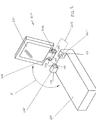
- Figures 1 and 2 illustrate a video camera 210 embodying the invention in which a mechanical coupling 202 is provided between a main body 200 and a rotatable display screen 201 of the video camera 210 with the arc X in Figure 1 illustrating the angle through which the display screen may be rotated relative to the main body of the video camera.
- Capacitive wireless coupling 205 and 206 is incorporated in the mechanical coupling 202 by means of which the display screen 201 derives a power supply and by means of which data is communicated between the main body 200 and the display screen 201.
- the mechanical coupling between the main body and the display screen is in the form of a hinge assembly 202 as is conventional for such video cameras.
- the multi-wire cable connection (generally a flat ribbon cable) normally provided within the hinge assembly to electrically connect the main body and the display screen is replaced by capacitive wireless coupling.
- the hinge assembly comprises first and second aligned but spaced-apart hinge members 101 and 102 carried by the main body 200 and a third elongate hinge member 103 carried by the display screen 201.
- the third elongate hinge member 103 may be carried by the man body 200 and the hinge members 101 and 102 by the display screen 201.
- the ends of the third hinge member have chamfered projecting regions 104 and 105 which are received in respective complementarily chamfered recesses (only one 106 of which can be seen in Figure 2 ) of the first and second hinge members 101 and 102 so that the third hinge member 103 can rotate about its axis relative to the first and second hinge members.
- the axis of the third hinge member thus defines the axis of rotation of the display screen 201 relative to the main body 200 of the video camera.
- the capacitive wireless coupling comprises two capacitive couplers each consisting of two capacitive coupling elements separated by a dielectric. Each capacitive coupling element is a circular electrically conductive plate 205 or 206.
- the capacitive coupling elements 205 are fitted into the recesses 106 of the first and second hinge members and the capacitive coupling elements 206 are carried by the projecting regions 104 of the third hinge member 103 to define two sets of parallel spaced-apart electrically conductive plates that are coaxial with the rotation axis of the hinge.
- the dielectric may simply be air or could be any suitable material providing the required dielectric and friction properties, for example a plastics material such as polyethylene or polytetrafluorethylene (PTFE) (which has the advantage of a very low coefficient of friction), or a ceramics material.
- first electrical connections are made between electric circuitry within the main body 200 and the capacitive plates 205 fitted into the recesses 106 and second electrical connections are made between electric circuitry within the display screen and the capacitive plates 206 carried by the projecting regions 104 of the third hinge member 103 of the display screen 201.
- These electrical connections may be made by, for example, insulated wires passing through the hinge members.
- the capacitive wireless coupling thus comprises two capacitive wireless couplers located within the hinge assembly and each comprising two parallel coaxial plates or discs 205 and 206. A minimum of two such capacitive wireless couplers is provided to ensure a flow and return current path. However multiple capacitive wireless couplers may also be used.
- FIG 3 shows a diagram representing one of the pairs of capacitive plates shown in Figure 2 for explaining the operation of the capacitive wireless coupling.
- the capacitance may be controlled to meet the requirements of a particular apparatus by adjusting any one or more of ⁇ , A and d.
- ⁇ and A should be maximised and d minimised.
- d is of the order of a few micrometres.
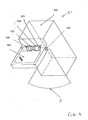
- Figures 4 and 5 show simplified perspective views of another video camera 510 embodying the invention which differs from that described above in both the form of the mechanical coupling and the form of the wireless capacitive coupling.
- Figure 7 shows a cross-sectional view through part of the apparatus to show how the capacitive coupling is incorporated into the mechanical coupling.
- the mechanical coupling comprises a hinge assembly having first and second aligned but spaced-apart hinge members 601 and 602 carried by the main body 500, and a third elongate hinge member 603 carried the display screen 501.
- the third elongate hinge member 603 may be carried by the main body 500 and the hinge members 601 and 602 by the display screen 501.
- the third elongate hinge member 603 is in the form of a hollow cylinder and the first and second spaced-apart hinge members 601 and 602 carry cylindrical projections 607 and 608 that are received within respective ends of the hollow cylinder 603 so that the third hinge member can rotate about its axis relative to the first and second hinge members.
- the axis of the third hinge member thus defines the axis of rotation of the display screen 501 relative to the main body 500 of the video camera 510.
- each capacitive coupling element is in the form of an electrically conductive cylinder so that each capacitive coupler consists of two coaxial cylinders separated by a dielectric.
- a dielectric 407 ( Figure 6 ) which again may simply be air or could be any suitable material providing the required dielectric and friction properties, for example a plastics material such as polyethylene or polytetrafluorethylene ((PTFE) which has the advantage of a very low coefficient of friction), or a ceramics material.
- PTFE polytetrafluorethylene
- the cylinders 400 and 401 may be provided as for example electrically conductive coatings deposited onto the projections 607 and 608 and the interior of the hollow cylinder 603 or as separate electrically conductive cylinders mounted on the projections 607 and 608 and within the hollow cylinder 603.
- first electrical connections are made between electric circuitry within the main body 500 and the capacitive cylinders 400 carried by the projections 607 and 608 and second electrical connections are made between electric circuitry within the display screen and the capacitive cylinders 401 carried within the third elongate hinge member 603 of the display screen 501.
- These electrical connections may be made by for example insulated wires passing through the hinge members.
- This capacitive wireless coupling thus comprises two capacitive wireless couplers located within the hinge assembly and each comprising two parallel coaxial cylinders 400 and 401. Again, although two such capacitive wireless couplers are shown to ensure a flow and return current path, multiple capacitive wireless couplers may also be used.
- FIG 7 shows a diagram for explaining the operation of the capacitive wireless coupler shown in Figures 4 to 6 .
- the capacitance of such a capacitive coupler may be controlled to meet the requirements for a particular application by adjusting any one or more of r 2 , r 1 , l and ⁇ . Thus, to maximise the capacitance:
- the mechanical couplings enable rotation about a single axis and the capacitive coupling elements have circular or cylindrical symmetry.
- the present invention may also be applied where the mechanical coupling enables rotation about more than one axis or enables displacement of one component of an apparatus relative to another.
- Figure 8 shows a cross-section through part of another apparatus embodying the invention in the region of the mechanical coupling.
- the mechanical coupling is in the form of a three dimensional ball-joint rotatable into and out of the plane of the paper in arc Y and rotatable in the plane of the paper in arc Z.
- the capacitive coupling is provided so that the outer surface 304 of the ball 302 forms one capacitive coupling element and the inner surface 305 of the socket 301 forms the other capacitive coupling element with the two being separated by a dielectric 303 which may be air or one of the materials mentioned above.
- the ball and socket themselves may be electrically conductive or they may have electrically conductive coatings to provide the capacitive coupling elements.
- the capacitive coupling should comprise at least two capacitive couplers. Where the apparatus requires two such ball and socket joints, this may be achieved by forming both of the ball and socket joints as capacitive couplers of the form shown in Figure 8 .
- FIG 9 shows a modified form of the ball and socket coupling shown in Figure 8 in which at least two separate capacitive coupling elements 307 and 308 are provided on the ball and corresponding capacitive coupling element 306 and 309 are provided on the socket to provide at least two capacitive couplers 306 and 307 and 308 and 309.
- these capacitive coupling elements are shown as being relatively small it will be appreciated that they should be made as large as is possible without causing cross-talk to provide sufficient overlap between the respective capacitive coupling elements of a capacitive coupler throughout the required range of movement of the ball joint over which the wireless coupling is to be effective.
- the capacitive coupling elements may be provided by electrically conductive regions deposited onto or applied to the ball and socket, or such regions may be made part of the ball and socket on manufacture.
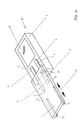
- FIG 10 shows a simplified perspective view of another embodiment of apparatus in accordance with the invention in the form of a portable electronic device 10 such as a portable digital assistant (PDA) having a main body 1 with a display screen 2 and a protective cover 3 that is slidable in the direction W.
- the protective cover 3 incorporates circuitry, for example a passive data storage device or possibly a small digital camera.
- the capacitive wireless coupling is provided by part of the slidable mechanical coupling.
- the slidable mechanical coupling is provided in part by inverted T cross-section guide rails 9 on the underside of the cover arranged to be received in correspondingly shaped guide grooves 10 on the main body 1 when the cover is in a closed condition covering the display screen 2 and in part by elongate recesses 5 provided on the underside of the cover 3 and complementary elongate projections 6 carried by the main body.
- Each of the elongate recesses 5 and complementary elongate projections 6 provides or carries an elongate capacitive coupling element 7 and 8 extending in the direction in which the cover is slidable.
- the dielectric is in this case provided by a small air gap between the cover and the main body.
- the lengths and relative positions of the elongate capacitive coupling elements 7 and 8 in the direction of sliding are selected so as to provide sufficient capacitive coupling to enable power and data to be communicated between the main body 1 and the slidable cover 3 over the desired range of movement of the cover 3 within which wireless communication is to be effective. This range may depend upon whether the electrical circuitry carried by the cover 3 is designed to be active when the cover is closed or when the cover is open sufficiently to expose the whole of the display, for example.
- electric connections extend through the main body to the elongate capacitive coupling elements 7 and through the cover to the elongate capacitive coupling elements 8.
- two capacitive couplers are provided to provide a flow and a return path, additional capacitive couplers may also be provided.
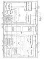
- Figure 11 shows a simplified functional block diagram of apparatus embodying the invention for illustrating communication via the wireless coupling associated with the mechanical coupling.
- Blocks 700 and 701 in Figure 11 represent the two components of the apparatus that are coupled together by the mechanical coupling, itself represented by block 702.
- the apparatus is a video camera with a movable screen as described above with reference to Figures 1 to 3 or Figures 4 to 7 and block 700 represents the functional components of the main body of the video camera while block 701 represents the functional components of the display screen.
- the wireless coupling is show simply as two blocks 703 and 704, with block 704 representing the return wireless coupler.
- the functional components of the main body include camera circuitry 705 having all of the normal components of the camera such as the power supply, processor control circuitry for controlling the camera lens assembly and overall operation of the camera and data processing circuitry for generating data in a form suitable for transmission via the mechanical coupling to the display screen.
- the functional components of the display screen include display circuitry 706 having the usual driving circuitry for controlling driving of the display of the display screen, for example an LCD (Liquid Crystal Display) driver interface, LCD driver and a data store where the display is an LCD device.
- LCD Liquid Crystal Display
- the camera main body 700 also includes power and data supply control circuitry that controls communication of power and data between the main body and the display screen via the wireless couplers 703 and 704.
- the power and data supply control circuitry includes an interface 707 that enables the power and data supply control circuitry to communicate with the camera circuitry 705.
- the power and data supply control circuitry is powered by the camera power supply. This is represented in Figure 11 by coupling the camera circuitry 705 to power supply lines 730 and 731. In the interests of simplicity the connections of the other functional components of the main body to the power supply lines 730 and 731 are not shown in Figure 11 .
- the power and data supply control circuitry may alternatively be self-powered, for example by means of a battery.
- the main body power and data supply control circuitry has a main body controller 708 that communicates with a processor of the camera circuitry 705 via the interface 707 and that controls the operations necessary to enable communication of data between the display screen and the main body via the wireless coupling.
- the display screen is not self-powered so the controller 710 also controls the supply to the display screen of a signal from which the display screen derives a power supply as will be described below.
- the main body power and data supply control circuitry includes a signal generator 712 for generating an alternating (AC) signal which is supplied to the main body capacitive coupling element of the wireless coupler 703 and a main body data transmitter 709 for supplying data to the display screen via the wireless coupling.
- the data transmitter 709 may, for example, transmit data under the control of the main body controller 708 by modulating the signal supplied by the signal generator 712 (or a separate carrier signal) in accordance with data supplied by the main body controller 708, generally under the control of the camera control circuitry 705 via the interface 707. Any appropriate modulation scheme such as amplitude, phase or frequency modulation may be used.
- any suitable data coding scheme may be used, although generally a NRZ (non-return-to-zero) data code will be used.
- a separate carrier signal it may be, for example, a 13.56 MHz carrier signal, although different carrier signals may be used for different signal types or application requirements.
- the signal supplied by the signal generator 712 may be a continuous signal or a burst signal with, in the latter case, the capacitive coupling enabling communication between the main body and the display screen in bursts, depending upon the particular apparatus.
- the signal generator 712 may form part of the main body data transmitter 709.
- the display screen 701 also includes power and data supply control circuitry.
- a DC power supply for the display screen is derived by a power deriver 724 coupled between the power supply lines 732 and 733 from a signal capacitively coupled to the display screen via the wireless coupling.
- a power deriver 724 coupled between the power supply lines 732 and 733 from a signal capacitively coupled to the display screen via the wireless coupling.
- the power deriver 724 may comprise a diode, diode array or bridge rectifier.
- the power deriver 724 may comprise respective diodes coupled between the display screen capacitive coupling element of the wireless coupler 703 and the power supply lines 732 and 733 of the display screen.
- Figure 12 illustrates one way in which the power deriver 724 may function.
- 801 represents the source of the AC signal to be capacitively coupled to the display screen via the capacitive couplers 703 and 704 and from which power is to be derived across the coupling field. This signal may be provided by the signal generator 712 in Figure 11 .
- the power deriver 724 comprises a bridge rectifier which generates a DC power supply from the signal capacitively coupled across the wireless coupling.
- the amount of power transferable is proportional to frequency and capacitance of the coupling field and, for a given capacitance, the higher the frequency of the signal the greater the conversion efficiency.
- power derived via the capacitive coupling may be stored at the display screen side, for example by the use of storage capacitors, so that the stored power can then be used as needed.
- This also has the advantage of allowing some control of power usage and allowing increase in power availability when power demand increases.
- Providing an ability to store power means that, for example, power could be transferred and stored when the system is 'at rest'.
- power could be transferred when the display screen of the video camera is in a closed configuration and the main camera is dormant.
- power could be transferred when the camera is active but the user is not using the display screen.
- a clock signal for the screen controller 720 is derived by a clock recoverer 723 from a clock signal supplied separately by a clock generator 711 of the main body 700 via the wireless coupler 703.
- the clock generator 711 may be an independent clock generator or may be arranged to derive a clock signal from a crystal clock of the main body controller 708.
- the clock recoverer 723 may derive a clock signal from a signal capacitively coupled to the clock recoverer 723 as described in WO02/052419 , for example from the signal supplied by the signal generator 712, or from a separate carrier signal provided via the wireless coupler 703.
- the screen controller 720 may have a separate clock signal supplier in the form of its own crystal clock in which case the clock recoverer 723 will be omitted.
- the display screen may need to communicate data to the main body. If so, the display screen functional components will include a screen data transmitter 722 that, under the control of the screen controller 720, causes data to be supplied to the main body via the capacitive coupling.
- the screen data transmitter 722 may communicate data by modulating a signal (for example the signal from the signal generator or a carrier signal) that is capacitively coupled to the display screen via the wireless coupler, as for example described in WO02/052419 , WO00/31676 or WO02/093881 .
- the screen data transmitter 722 will use the same modulation and data coding schemes as the main body transmitter, although this is not necessary as long as the main body data receiver 710 and demodulator 710 and main body controller 708 use the appropriate demodulation and decoding schemes.
- the main body data controller 708 is a separate circuit within the camera main body. It may however be fully or partially provided by the main camera processor of the camera circuitry 705, in which case the interface 707 that ensures compatibility between received and/or transmitted signals and the main camera processor may not be required.
- the display screen derives a power supply from a signal supplied by the main body via the capacitive coupling.
- the display screen may be self-powered, in which case the power deriver will be a battery and the connection to the capacitive coupling element of the wireless coupler will be omitted.
- both battery and separate power derivation means for deriving power via the capacitive coupling may be provided within the display screen.
- the data that may need to be supplied from the camera main body to the display screen assembly includes lens details, image details, light detection details and so on while the data that may need to be supplied from the display screen to the camera main body assembly includes user commands input via the screen, for example. It may be, however, that data only needs to be transferred in one direction.
- the sub-system may have limited intelligence and may supply no operating parameters to the main system.
- the rate of data transfer required may be for example 10 to 40 Mbps (Mega bits per second0 or 200 to 600 Mbps per pair of capacitive plates or for example as specified by the video electronics standards association (e.g. VESA MDDI specification).
- the wireless capacitive couplers 703 and 704 of the apparatus illustrated by Figure 11 may have any of the forms described above that are suitable for use with the particular type of mechanical coupling 702 used between the main body and the display screen. As shown in Figure 11 , two capacitive couplers are provided to ensure provision of a flow and return path across the mechanical coupling. As mentioned above, multiple wireless couplers may be associated with one mechanical coupling, for example incorporated into a single hinge assembly. These different wireless couplers may be used to transfer the same data or may be used for different purposes. Where they are used for different purposes it is possible to have different degrees of capacitive coupling for different couplers and therefore to achieve different rates of data transfer or power transfer. As another possibility, different methods of data transmission can be used for transmission of data across different couplings.
- the capacitive couplers shown in Figures 1 to 7 and 8 provide a constant capacitive coupling regardless of the degree of rotation which has the advantage that the capacitive coupling is always the same regardless of any change in the configuration of the apparatus, that is regardless of the degree of rotation of the display screen relative to the main body of the camera.
- the degree of overlap between the capacitive coupling elements and thus the degree of capacitive coupling in Figures 9 and 10 varies with the degree of movement or rotation.
- FIG. 1 to 7 different geometries may be adopted (for example to enable a better fit to the hinge assembly) where the degree of coupling varies with the rotation of the display screen provided that sufficient capacitive coupling is achieved over the range of rotation of the display screen.
- the capacitive coupling elements in Figures 1 to 7 may in any case be modified so that the degree of coupling varies with rotation of the screen. This could be achieved by, for example, forming the capacitive coupling elements by providing metallization only around part of the surface of non-conducting circular elements ( Figures 1 and 2 ) or cylindrical non-conducting elements ( Figures 4 to 6 ).
- one of the main body and screen controllers 708 and 720 may be configured to determine the coupling capacitance and to compare it against a reference capacitance to determine the degree of rotation (or movement in the case of Figure 10 ) of the display screen or cover relative to the main body. This may enable determination as to when the cover in Figure 10 is open or closed and when the display screen in Figures 1 to 7 is in a fully rotated or a closed condition.
- Such information regarding the relative orientations or positions of the two components or sub-assemblies may be used by one or other of the controllers 708 and 720 in determining what data may be transmitted so that, for example, certain data may be transmitted only when the display is fully exposed (fully rotated in Figures 1 to 7 or the cover is fully opened in Figure 11 ) or certain data transmitted only when the display is not rotated or the cover is closed, or to determine when power can be transferred, for example when the display is fully covered, for example.
- the wireless coupling is capacitive.
- the capacitive coupling may be replaced by an inductive coupling.
- Figure 13 illustrates an inductive coupler that may be used in place of the capacitive coupler shown in Figures 1 to 3 .
- the inductive coupler consists of two inductive coupling elements in the form of coaxial planar coils 801 and 802.
- the efficiency of this inductive coupler is governed primarily by the distance between the two coil planes, which should be as small as possible, typically about 1mm (millimetre).
- Figure 14 illustrates an inductive coupler that may be used in place of the capacitive coupler shown in Figures 4 to 7 .
- the inductive coupling elements are in the form of two coaxial cylindrical coils (solenoid coils) 901 and 902.
- the present invention can be applied to any apparatus in which components or sub-assemblies are coupled by a mechanical coupling so that the configuration of the apparatus can be varied by effecting relative rotation and/or displacement or movement between the coupled components and in which at least one of data or power is to be transferred between the components.
- Examples of such apparatus in addition to the video cameras mentioned above, are: laptop computers and personal data assistants (PDAs), video display units, screen based GPS systems and electronic test equipment, other screen based systems or units or other apparatus with similar assemblies or mechanisms.
- PDAs personal data assistants
- the present invention has particular application to portable devices, that is devices such as PDAs that can easily be carried by a human being, but can also be applied to larger devices that may be transportable or may be fixed in place.
- the present invention may also be applied where components are coupled in series by respective mechanical couplings and at least one of data or power is to be transferred across at least one of the mechanical couplings.
- the invention may also be of use in apparatus in which two sub-systems or components are relatively displaceable or rotatable to achieve mechanical coupling, but in which, relative movement is not possible after the components are coupled.
- the degree of coupling (whether capacitive or inductive) can be tailored to meet the requirements of the particular apparatus by adjusting any of the factors that control the degree of coupling.
- the degree of coupling can be tailored to meet requirements dependent upon, for example, any one or more of the type of data being transferred, the amount of data being transferred, the rate of data transfer, the requirement for power transfer and the number of couplers included within or associated with a given mechanical coupling.
- the ability to vary physical constraints within the mechanical coupling creates increased flexibility within the mechanical coupling or sub-assembly.
- the capacitive or inductive coupling elements need not have the geometries mentioned above but may have any geometry that is compatible with the particular mechanical coupling of the apparatus.
- a return coupler is required. Where at least part of the apparatus is designed to be handheld or otherwise contacted by a user or other grounded object, it may be possible to provide a capacitive coupling in which the user or other object provides a ground return path in a manner similar to that described in WO00/31676 , so removing the need for a return coupler.
- An embodiment provides a variable configuration apparatus having components or sub-systems, wherein at least some components have mechanical coupling elements that enable the configuration of the apparatus to be varied by changing at least one of the relative orientation and position of those components or sub-systems.
- These mechanical coupling elements incorporate wireless signal coupling elements that cooperate to provide a wireless coupling which enables wireless coupling between the components.
- the wireless coupling may be used to transfer at least one of data and power between the components.
- the wireless signal coupling elements may be capacitive coupling elements that provide capacitive coupling between the components or sub-systems.
- the apparatus is a video camera and one component or sub-system is a display screen and another component or sub-system is the main body of the video camera. Apparatus embodying the invention allows, by virtue of the wireless coupling, a greater level of stress isolation to exist between the relatively movable components or sub-systems, which should reduce stress based failures.
- Apparatus embodying the invention allows increased flexibility so that different components or sub-systems can be utilised without any requirement to replace the mechanical or galvanic connectors typical in such systems.
- the apparatus comprises a video camera and the mechanically coupled components comprise the camera main body and a display screen
- the screen may be replaced with a different screen or different functional unit and the same wireless data and power transfer used between the main body of the camera system and the new screen or functional unit.
- the capacitive or inductive coupling elements need merely be brought within operating range. This provides for interchangeability of parts. Such interchangeability may have additional advantages in the context of power transfer. For example re-charging could be provided through the mechanical coupling.
- a battery could be replaced within one component and power transferred to another mechanically coupled component, so removing the need for a separate charging station.
Claims (18)
- Appareil comprenant des premier (200) et second (201) composants ayant des premiers (101, 102) et seconds (103) éléments de couplage mécaniques respectifs coopérant pour permettre le mouvement relatif des premier (200) et second (201) composants, le premier élément de couplage mécanique (101, 102) comprenant un renfoncement (106) formé à l'intérieur et le second élément de couplage mécanique (103) comprenant une saillie (104) conçue pour être ajustée de façon mobile dans le renfoncement (106) ;
dans lequel le premier élément de couplage mécanique (101, 102) comprend une première plaque conductrice (205) ayant une première surface, ladite première plaque conductrice (205) étant positionnée dans le renfoncement (106) et le second élément de couplage mécanique (103) comprend une seconde plaque conductrice (206) ayant une seconde surface, ladite seconde plaque conductrice (206) étant positionnée sur la saillie (104), dans lequel la première surface de la première plaque conductrice (205) est positionnée sensiblement parallèlement à la seconde surface de la seconde plaque conductrice (206) lorsque la saillie (104) est ajustée dans le renfoncement (106), ladite première surface de ladite première plaque conductrice (205) étant séparée de ladite seconde surface de ladite seconde plaque conductrice (206) par un diélectrique ;
dans lequel les première et seconde plaques conductrices (205, 206) sont en outre configurées pour coupler sans fil un signal provenant d'un composant parmi les premier (200) et second (201) composants à l'autre composant parmi les premier (200) et second (201) composants. - Appareil selon la revendication 1, dans lequel au moins un composant parmi les premier (200) et second (201) composants a un fournisseur de données servant à communiquer des données à l'autre composant parmi les premier (200) et second (201) composants via le couplage sans fil fourni par les premier (205) et second (206) systèmes de couplage.
- Appareil selon la revendication 1, dans lequel au moins un composant parmi les premier (200) et second (201) composants a un fournisseur de signal (712, 720) couplé à une plaque parmi la première plaque conductrice (205) ou la seconde (206) plaque conductrice pour amener un signal à coupler à l'autre composant parmi les premier (200) et second (201) composants via le couplage sans fil et dans lequel au moins un composant parmi les premier (200) et second (201) composants est agencé pour communiquer des données à l'autre composant en modulant ce signal.
- Appareil selon la revendication 1, dans lequel au moins un composant parmi les premier (200) et second (201) composants a un dériveur de courant (724) pouvant être actionné pour dériver une alimentation électrique de ce composant à partir d'un signal couplé à ce composant en partant de l'autre composant, via le couplage sans fil.
- Appareil selon la revendication 4, dans lequel le dériveur de courant (724) comprend un redresseur.
- Appareil selon la revendication 4, dans lequel le dériveur de courant (724) comprend un redresseur et un élément de stockage de charge.
- Appareil selon la revendication 1, dans lequel la première plaque conductrice (205) et la seconde plaque conductrice (206) fournissent au moins un couplage sans fil parmi un couplage sans fil capacitif et un couplage sans fil inductif.
- Appareil selon la revendication 1, dans lequel le degré de couplage entre la première plaque conductrice (205) et la seconde plaque conductrice (206) varie avec les positions ou orientations relatives des premier (200) et second (201) composants et dans lequel un élément de détermination (708, 720) est prévu pour déterminer le degré de couplage, pour déterminer des informations relatives aux positions et/ou orientations relatives des premier (200) et second (201) composants.
- Appareil selon la revendication 1, dans lequel les premiers (101, 102) et seconds (103) éléments de couplage mécaniques définissent au moins un couplage parmi un couplage pouvant tourner et un couplage pouvant coulisser.
- Appareil selon la revendication 1, dans lequel les premiers (101, 102) et seconds (103) éléments de couplage mécaniques servent de parties coaxiales à une charnière.
- Appareil selon la revendication 1, dans lequel les premiers (101, 102) et seconds (103) éléments de couplage mécaniques définissent un agencement de balle et raccord.
- Appareil selon la revendication 1, dans lequel les premiers (101, 102) et seconds (103) éléments de couplage mécaniques fournissent un couplage mécanique coulissant permettant un coulissement relatif entre les premier (200) et second (201) composants.
- Appareil selon la revendication 1, dans lequel les positions et/ou orientations relatives des premier (200) et second (201) composants sont fixes dès que le couplage mécanique est réalisé.
- Appareil selon la revendication 1, dans lequel les premier (200) et second (201) composants sont des sous-systèmes ou des sous-ensembles.
- Appareil selon la revendication 1, dans lequel le second composant (201) est un dispositif d'affichage.
- Appareil selon la revendication 1, sous la forme d'un ordinateur portable, d'un assistant personnel de type PDA, d'une unité d'écran vidéo, d'une caméra vidéo ou d'un système GPS.
- Procédé de couplage sans fil d'un signal dans un appareil ayant des premier (200) et second (201) composants ayant des premiers (101, 102) et seconds (103) éléments de couplage mécaniques respectifs coopérant pour permettre le mouvement relatif des premier (200) et second (201) composants, le premier élément de couplage mécanique (101, 102) comprenant un renfoncement (106) formé à l'intérieur et le second élément de couplage mécanique (103) comprenant une saillie (104) conçue pour être ajustée de façon mobile dans le renfoncement (106), le premier élément de couplage mécanique (101, 102) comprenant une première plaque conductrice (205) ayant une première surface, ladite première plaque conductrice (205) étant positionnée dans le renfoncement et le second élément de couplage mécanique (103) comprenant une seconde plaque conductrice (206) ayant une seconde surface, ladite seconde plaque conductrice (206) étant positionnée sur la saillie (104), dans lequel la première surface de la première plaque conductrice (205) est positionnée sensiblement parallèlement à la seconde surface de la seconde plaque conductrice (206) lorsque la saillie (104) est ajustée dans le renfoncement (106), ladite première surface de ladite première plaque conductrice (205) étant séparée de ladite seconde surface de ladite seconde plaque conductrice (206) par un diélectrique ;
le procédé comprenant le couplage sans fil du signal du premier composant (200) au second composant (201) via la première plaque conductrice (205) et la seconde plaque conductrice (206) comprises dans les premier (200) et second (201) composants. - Appareil selon la revendication 1, dans lequel les premiers (101, 102) et seconds (103) éléments de couplage mécaniques comprennent des moyens de couplage de signal respectifs ayant des premier (205) et second (206) dispositifs conducteurs respectifs formés par les première (205) et seconde (206) plaques conductrices, de telle sorte que les moyens de couplage de signal couplent sans fil le signal allant d'un composant parmi les premier (200) et second (201) composants à l'autre composant parmi les premier (200) et second (201) composants.
Applications Claiming Priority (4)
| Application Number | Priority Date | Filing Date | Title |
|---|---|---|---|
| GB0400805A GB0400805D0 (en) | 2004-01-14 | 2004-01-14 | Apparatus and method for communicating data |
| GB0402588A GB0402588D0 (en) | 2004-02-05 | 2004-02-05 | Apparatus and method for transferring data or power |
| GB0410242A GB0410242D0 (en) | 2004-05-07 | 2004-05-07 | Apparatus and method for transferring data or power |
| PCT/GB2005/000122 WO2005069585A1 (fr) | 2004-01-14 | 2005-01-14 | Appareil a configuration variable |
Publications (2)
| Publication Number | Publication Date |
|---|---|
| EP1704703A1 EP1704703A1 (fr) | 2006-09-27 |
| EP1704703B1 true EP1704703B1 (fr) | 2013-08-28 |
Family
ID=34799126
Family Applications (1)
| Application Number | Title | Priority Date | Filing Date |
|---|---|---|---|
| EP05701890.5A Not-in-force EP1704703B1 (fr) | 2004-01-14 | 2005-01-14 | Appareil a configuration variable |
Country Status (4)
| Country | Link |
|---|---|
| US (2) | US7751860B2 (fr) |
| EP (1) | EP1704703B1 (fr) |
| JP (2) | JP4685032B2 (fr) |
| WO (1) | WO2005069585A1 (fr) |
Families Citing this family (37)
| Publication number | Priority date | Publication date | Assignee | Title |
|---|---|---|---|---|
| WO2005069585A1 (fr) | 2004-01-14 | 2005-07-28 | Innovision Research & Technology Plc | Appareil a configuration variable |
| US20080004003A1 (en) * | 2006-06-28 | 2008-01-03 | Thomas Wulff | Mobile device with detachable accessory |
| US8295899B2 (en) * | 2006-09-21 | 2012-10-23 | Kyocera Corporation | Mobile wireless device with an inductive coupler |
| US7966047B2 (en) * | 2007-06-12 | 2011-06-21 | Sony Ericsson Mobile Ab | Wireless terminals with integrated high speed serial communication hinges |
| JP5001750B2 (ja) * | 2007-08-27 | 2012-08-15 | エスアイアイ・データサービス株式会社 | 携帯情報処理装置 |
| US7877123B2 (en) * | 2007-09-28 | 2011-01-25 | Motorola Mobility, Inc. | Method and apparatus for RF signal transmission in a slider phone |
| US7962186B2 (en) * | 2007-10-24 | 2011-06-14 | Nokia Corporation | Method and apparatus for transferring electrical power in an electronic device |
| JP2009169327A (ja) * | 2008-01-21 | 2009-07-30 | Hitachi Displays Ltd | 電力伝送回路 |
| US8854296B2 (en) * | 2008-08-01 | 2014-10-07 | Nokia Corporation | Electronic device wireless display |
| US9191263B2 (en) | 2008-12-23 | 2015-11-17 | Keyssa, Inc. | Contactless replacement for cabled standards-based interfaces |
| US9219956B2 (en) | 2008-12-23 | 2015-12-22 | Keyssa, Inc. | Contactless audio adapter, and methods |
| US8199493B2 (en) * | 2009-08-20 | 2012-06-12 | Nokia Corporation | Rotational apparatus for communication |
| CN102097830B (zh) * | 2009-12-14 | 2013-07-03 | 鸿富锦精密工业(深圳)有限公司 | 电子装置 |
| JP2012019382A (ja) | 2010-07-08 | 2012-01-26 | Sony Corp | 電子機器 |
| GB2484299B (en) * | 2010-10-05 | 2012-10-10 | Aeroflex Ltd | A locking system |
| JP5619565B2 (ja) * | 2010-10-27 | 2014-11-05 | 京セラ株式会社 | 通信装置 |
| US8611078B2 (en) * | 2010-12-29 | 2013-12-17 | Nokia Corporation | Method and apparatus for displays |
| CN102185233B (zh) * | 2011-02-22 | 2014-09-10 | 中兴通讯股份有限公司 | 一种旋转usb接口类设备 |
| US20140152094A1 (en) * | 2011-08-16 | 2014-06-05 | Koninklijke Philips N.V. | Capacitive wireless power inside a tube-shaped structure |
| US9729685B2 (en) * | 2011-09-28 | 2017-08-08 | Apple Inc. | Cover for a tablet device |
| US9577713B2 (en) | 2011-09-29 | 2017-02-21 | Konica Minolta Laboratory U.S.A., Inc. | Method and system for aligning conductors for capacitive wireless power transmission |
| US8736114B2 (en) | 2011-09-29 | 2014-05-27 | Konica Minolta Laboratory U.S.A., Inc. | Method and system for aligning conductors for capacitive wireless power transmission |
| US9176536B2 (en) * | 2011-09-30 | 2015-11-03 | Apple, Inc. | Wireless display for electronic devices |
| US8847979B2 (en) | 2012-06-08 | 2014-09-30 | Samuel G. Smith | Peek mode and graphical user interface (GUI) experience |
| JP6216951B2 (ja) * | 2012-07-12 | 2017-10-25 | 学校法人慶應義塾 | 方向性結合式通信装置 |
| US9529737B2 (en) | 2012-08-10 | 2016-12-27 | Keyssa, Inc. | EHF data transmission among enclosures in hinged systems |
| KR101873624B1 (ko) * | 2012-08-10 | 2018-07-31 | 키사, 아이엔씨. | Ehf 가능 디스플레이 시스템 |
| US9118356B2 (en) * | 2013-02-19 | 2015-08-25 | Apple Inc. | Data transport in portable electronic devices |
| US9645721B2 (en) | 2013-07-19 | 2017-05-09 | Apple Inc. | Device input modes with corresponding cover configurations |
| DE202015009067U1 (de) * | 2014-11-19 | 2016-08-24 | Rosenberger Hochfrequenztechnik Gmbh & Co. Kg | Magnetische Verbindungsvorrichtung |
| GB2537885B (en) * | 2015-04-29 | 2017-04-05 | Eureco Tech Ltd | Deployable radio frequency transmission line |
| US9602648B2 (en) | 2015-04-30 | 2017-03-21 | Keyssa Systems, Inc. | Adapter devices for enhancing the functionality of other devices |
| US10175922B2 (en) * | 2017-01-17 | 2019-01-08 | Dell Products L.P. | Wirelessly communicating data between two housings of a computing device |
| JP2019146465A (ja) * | 2017-08-31 | 2019-08-29 | 株式会社リューテック | 非接触給電装置 |
| US11556153B2 (en) * | 2019-07-01 | 2023-01-17 | Microsoft Technology Licensing, Llc | Electrostatic clutch for active control of free hinge |
| TWI727783B (zh) | 2020-05-05 | 2021-05-11 | 華碩電腦股份有限公司 | 筆記型電腦 |
| US11644871B1 (en) * | 2022-02-11 | 2023-05-09 | Dell Products L.P. | Systems and methods for determining hinge angle position in an information handling system |
Family Cites Families (44)
| Publication number | Priority date | Publication date | Assignee | Title |
|---|---|---|---|---|
| JPS60134543A (ja) * | 1983-12-22 | 1985-07-17 | Sharp Corp | 非接触型デ−タ転送方式 |
| JPS645235U (fr) | 1987-06-24 | 1989-01-12 | ||
| JPS645235A (en) * | 1987-06-29 | 1989-01-10 | Oki Electric Ind Co Ltd | Capacitive coupling type rotary coupler |
| JPH0394180A (ja) | 1989-09-06 | 1991-04-18 | Mitsubishi Electric Corp | 半導体素子の特性測定装置 |
| JPH0394180U (fr) * | 1990-01-16 | 1991-09-25 | ||
| JP3094180B2 (ja) | 1992-03-12 | 2000-10-03 | 祐作 滝田 | イソブタンの酸化脱水素によるイソブチレンの製造方法 |
| US5170173A (en) * | 1992-04-27 | 1992-12-08 | Motorola, Inc. | Antenna coupling apparatus for cordless telephone |
| EP0658280A4 (fr) * | 1993-05-03 | 1995-09-20 | Motorola Inc | Antenne pour un appareil electronique. |
| US5455466A (en) * | 1993-07-29 | 1995-10-03 | Dell Usa, L.P. | Inductive coupling system for power and data transfer |
| US5577026A (en) * | 1993-12-28 | 1996-11-19 | Analogic Corporation | Apparatus for transferring data to and from a moving device |
| US5572441A (en) | 1994-04-04 | 1996-11-05 | Lucent Technologies Inc. | Data connector for portable devices |
| DE4444984C1 (de) | 1994-12-16 | 1995-12-14 | Siemens Ag | System zur kontaktlosen Datenübertragung |
| US5694516A (en) | 1995-05-22 | 1997-12-02 | Lucent Technologies Inc. | Capacitive interface for coupling between a music chip and audio player |
| JPH0926834A (ja) | 1995-07-12 | 1997-01-28 | Hitachi Maxell Ltd | 電子機器 |
| DE19542214C1 (de) | 1995-11-13 | 1997-03-27 | Frank Basner | Kommunikationssystem |
| GB2310765B (en) | 1996-03-01 | 2000-05-17 | Motorola Inc | Data carrier device,terminal and system |
| SG54559A1 (en) * | 1996-09-13 | 1998-11-16 | Hitachi Ltd | Power transmission system ic card and information communication system using ic card |
| JP3519554B2 (ja) * | 1996-09-20 | 2004-04-19 | 株式会社東芝 | 携帯型電子機器 |
| JPH10213411A (ja) * | 1997-01-30 | 1998-08-11 | Tokai Rika Co Ltd | 回転角度検出装置 |
| EP0916984A1 (fr) * | 1997-11-15 | 1999-05-19 | Canon Kabushiki Kaisha | Dispositif de déflexion d lumière et son réseau |
| IL122250A (en) * | 1997-11-19 | 2003-07-31 | On Track Innovations Ltd | Smart card amenable to assembly using two manufacturing stages and a method of manufacture thereof |
| US6272324B1 (en) * | 1998-09-28 | 2001-08-07 | Ericsson Inc. | Electrical connection for telephone with hinged cover |
| JP2000165124A (ja) | 1998-11-18 | 2000-06-16 | Telefon Ab Lm Ericsson | 携帯無線機、フリップ及びヒンジ |
| GB2344257A (en) | 1998-11-26 | 2000-05-31 | Innovision Research And Techno | Data communication apparatus and board game |
| TW463399B (en) * | 1999-03-19 | 2001-11-11 | Seiko Epson Corp | Electronic device |
| JP2001033136A (ja) | 1999-07-19 | 2001-02-09 | Sharp Corp | 冷蔵庫 |
| JP3623699B2 (ja) * | 1999-08-24 | 2005-02-23 | Necアクセステクニカ株式会社 | 卓上壁掛兼用型通信機器 |
| DE19940374A1 (de) | 1999-08-25 | 2001-03-08 | Michael Buhla | Verfahren zur Datenübertragung zwischen einem einer Einbaugarnitur zugeordneten Transponder und einem Datenerfassungsgerät sowie Anordnung |
| JP3637821B2 (ja) * | 1999-10-01 | 2005-04-13 | 松下電器産業株式会社 | Rfタグ用情報端末装置 |
| EP1096422A1 (fr) | 1999-10-25 | 2001-05-02 | Swatch Ag | Interface entre un lecteur à contact et un dispositif sans contact |
| JP3546784B2 (ja) * | 1999-12-14 | 2004-07-28 | 日本電気株式会社 | 携帯端末 |
| JP2001292085A (ja) * | 2000-04-10 | 2001-10-19 | Mitsubishi Electric Corp | 非接触伝送装置 |
| US6470132B1 (en) * | 2000-09-05 | 2002-10-22 | Nokia Mobile Phones Ltd. | Optical hinge apparatus |
| WO2002052419A2 (fr) | 2000-12-22 | 2002-07-04 | Innovision Research & Technology Plc | Appareil de communication de données |
| JP2004530380A (ja) | 2001-05-14 | 2004-09-30 | イノヴィジョン リサーチ アンド テクノロジー ピーエルシー | 電気装置 |
| JP3750587B2 (ja) * | 2001-11-05 | 2006-03-01 | 日本電気株式会社 | 折り畳み式携帯電話機 |
| US20030129950A1 (en) * | 2002-01-10 | 2003-07-10 | Min-Woo Kwak | Antenna of wireless phone |
| JP2003234809A (ja) | 2002-02-07 | 2003-08-22 | Toshiba Corp | 携帯情報端末 |
| JP2003244301A (ja) * | 2002-02-18 | 2003-08-29 | Nec Corp | 携帯情報端末 |
| US7257430B2 (en) * | 2002-05-11 | 2007-08-14 | Motorola, Inc. | Self configuring multiple element portable electronic device |
| US7356952B2 (en) * | 2002-06-17 | 2008-04-15 | Philip Morris Usa Inc. | System for coupling package displays to remote power source |
| US20040204199A1 (en) * | 2002-12-31 | 2004-10-14 | Zax Glenn Scott | Hand held communication device with decoupled antenna |
| GB0400805D0 (en) | 2004-01-14 | 2004-02-18 | Innovision Res & Tech Plc | Apparatus and method for communicating data |
| WO2005069585A1 (fr) | 2004-01-14 | 2005-07-28 | Innovision Research & Technology Plc | Appareil a configuration variable |
-
2005
- 2005-01-14 WO PCT/GB2005/000122 patent/WO2005069585A1/fr active Application Filing
- 2005-01-14 US US10/586,160 patent/US7751860B2/en not_active Expired - Fee Related
- 2005-01-14 EP EP05701890.5A patent/EP1704703B1/fr not_active Not-in-force
- 2005-01-14 JP JP2006548401A patent/JP4685032B2/ja not_active Expired - Fee Related
-
2010
- 2010-05-18 US US12/781,892 patent/US8306583B2/en active Active
- 2010-10-12 JP JP2010229878A patent/JP2011018374A/ja not_active Withdrawn
Also Published As
| Publication number | Publication date |
|---|---|
| US20100285672A1 (en) | 2010-11-11 |
| WO2005069585A1 (fr) | 2005-07-28 |
| JP4685032B2 (ja) | 2011-05-18 |
| EP1704703A1 (fr) | 2006-09-27 |
| JP2007526555A (ja) | 2007-09-13 |
| US20080039009A1 (en) | 2008-02-14 |
| JP2011018374A (ja) | 2011-01-27 |
| US7751860B2 (en) | 2010-07-06 |
| US8306583B2 (en) | 2012-11-06 |
Similar Documents
| Publication | Publication Date | Title |
|---|---|---|
| EP1704703B1 (fr) | Appareil a configuration variable | |
| US10141979B2 (en) | Apparatus and method for using near field communication and wireless power transmission | |
| EP1898530B1 (fr) | Système de communication, appareil de communication et antenne de couplage de champ électrique | |
| EP2932578B1 (fr) | Récepteur de puissance sans fil et procédé pour le commander | |
| KR102007226B1 (ko) | 이동 단말기 | |
| US20210384754A1 (en) | Accessory with a Magnetic Relay Structure for Wireless Power Transfer | |
| JP5150618B2 (ja) | アンテナ装置及び携帯端末機器 | |
| US11710984B2 (en) | Wireless charging system with simultaneous wireless power transfer at different frequencies | |
| WO2009018568A2 (fr) | Antennes déployables pour alimentation sans fil | |
| KR20110121856A (ko) | 소스-타겟 구조의 매칭을 제어하는 장치 및 방법 | |
| JP2008295274A (ja) | 無接点電力伝送コイルユニット、携帯端末、送電装置、及び、無接点電力伝送システム | |
| KR20120019090A (ko) | 공진 전력 전달 시스템에서 공진 임피던스 트래킹 장치 및 방법 | |
| KR101171937B1 (ko) | 자기공진유도 방식을 이용한 멀티노드 무선 전력 전송 시스템 및 무선 충전기기 | |
| US20220006327A1 (en) | Wireless Power Mode Switching | |
| US11429207B2 (en) | Capacitive-coupling electronic pen | |
| KR20170031905A (ko) | Nfc 장치의 태그 감지기, nfc 장치 및 이를 포함하는 모바일 장치 | |
| CN104734271A (zh) | 线圈装置、无线电力发送器和无线电力接收器 | |
| KR20180137773A (ko) | 사용자 단말에 탈부착되는 무선 충전 지원 액세서리 및 이에 기반한 무선 충전 시스템 | |
| KR101211062B1 (ko) | 배터리 정보 기반 멀티노드 무선 전력 전송 시스템 및 그 충전 방법 | |
| US6280258B1 (en) | Arrangements relating to electrical connections between apparatuses containing electrical circuitry | |
| KR102024015B1 (ko) | 모바일 기기의 사용에 대한 사용자의 편의성을 증대시키는 무선전력전송 장치 | |
| JP4544077B2 (ja) | 信号処理装置 | |
| CN101867395A (zh) | 通信装置 | |
| KR20180032349A (ko) | 코일 모듈 및 그를 이용한 무선 전력 송신 장치 | |
| KR20190071392A (ko) | Nfc 장치의 변조 인덱스 설정 회로, nfc 장치 및 nfc 장치의 동작 방법 |
Legal Events
| Date | Code | Title | Description |
|---|---|---|---|
| PUAI | Public reference made under article 153(3) epc to a published international application that has entered the european phase |
Free format text: ORIGINAL CODE: 0009012 |
|
| 17P | Request for examination filed |
Effective date: 20060717 |
|
| AK | Designated contracting states |
Kind code of ref document: A1 Designated state(s): AT BE BG CH CY CZ DE DK EE ES FI FR GB GR HU IE IS IT LI LT LU MC NL PL PT RO SE SI SK TR |
|
| RIN1 | Information on inventor provided before grant (corrected) |
Inventor name: SYMONS, PETER,INNOVISION RCH. & TECHNOLOGY PLC Inventor name: KEEN, IAN,INNOVISION RESEARCH & TECHNOLOGY PLC Inventor name: WARD, TIMOTHY,INNOVISION RCH. & TECHNOLOGY PLC Inventor name: UNDERWOOD, RICHARD,INNOVISION RCH. & TECHN. PLC Inventor name: LAMACRAFT, KEVIN,INNOVISION RCH. & TECHNOLOGY PLC |
|
| DAX | Request for extension of the european patent (deleted) | ||
| RAP1 | Party data changed (applicant data changed or rights of an application transferred) |
Owner name: J.M. STANNECK, LIMITED LIABILITY COMPANY |
|
| 17Q | First examination report despatched |
Effective date: 20100118 |
|
| GRAP | Despatch of communication of intention to grant a patent |
Free format text: ORIGINAL CODE: EPIDOSNIGR1 |
|
| GRAS | Grant fee paid |
Free format text: ORIGINAL CODE: EPIDOSNIGR3 |
|
| GRAA | (expected) grant |
Free format text: ORIGINAL CODE: 0009210 |
|
| AK | Designated contracting states |
Kind code of ref document: B1 Designated state(s): AT BE BG CH CY CZ DE DK EE ES FI FR GB GR HU IE IS IT LI LT LU MC NL PL PT RO SE SI SK TR |
|
| REG | Reference to a national code |
Ref country code: GB Ref legal event code: FG4D |
|
| REG | Reference to a national code |
Ref country code: CH Ref legal event code: EP |
|
| REG | Reference to a national code |
Ref country code: AT Ref legal event code: REF Ref document number: 629879 Country of ref document: AT Kind code of ref document: T Effective date: 20130915 |
|
| REG | Reference to a national code |
Ref country code: IE Ref legal event code: FG4D |
|
| REG | Reference to a national code |
Ref country code: DE Ref legal event code: R096 Ref document number: 602005041028 Country of ref document: DE Effective date: 20131024 |
|
| REG | Reference to a national code |
Ref country code: AT Ref legal event code: MK05 Ref document number: 629879 Country of ref document: AT Kind code of ref document: T Effective date: 20130828 |
|
| REG | Reference to a national code |
Ref country code: LT Ref legal event code: MG4D |
|
| REG | Reference to a national code |
Ref country code: NL Ref legal event code: VDEP Effective date: 20130828 |
|
| PG25 | Lapsed in a contracting state [announced via postgrant information from national office to epo] |
Ref country code: AT Free format text: LAPSE BECAUSE OF FAILURE TO SUBMIT A TRANSLATION OF THE DESCRIPTION OR TO PAY THE FEE WITHIN THE PRESCRIBED TIME-LIMIT Effective date: 20130828 Ref country code: SE Free format text: LAPSE BECAUSE OF FAILURE TO SUBMIT A TRANSLATION OF THE DESCRIPTION OR TO PAY THE FEE WITHIN THE PRESCRIBED TIME-LIMIT Effective date: 20130828 Ref country code: LT Free format text: LAPSE BECAUSE OF FAILURE TO SUBMIT A TRANSLATION OF THE DESCRIPTION OR TO PAY THE FEE WITHIN THE PRESCRIBED TIME-LIMIT Effective date: 20130828 Ref country code: CY Free format text: LAPSE BECAUSE OF FAILURE TO SUBMIT A TRANSLATION OF THE DESCRIPTION OR TO PAY THE FEE WITHIN THE PRESCRIBED TIME-LIMIT Effective date: 20130710 Ref country code: PT Free format text: LAPSE BECAUSE OF FAILURE TO SUBMIT A TRANSLATION OF THE DESCRIPTION OR TO PAY THE FEE WITHIN THE PRESCRIBED TIME-LIMIT Effective date: 20131230 Ref country code: IS Free format text: LAPSE BECAUSE OF FAILURE TO SUBMIT A TRANSLATION OF THE DESCRIPTION OR TO PAY THE FEE WITHIN THE PRESCRIBED TIME-LIMIT Effective date: 20131228 |
|
| REG | Reference to a national code |
Ref country code: NL Ref legal event code: VDEP Effective date: 20130828 |
|
| PG25 | Lapsed in a contracting state [announced via postgrant information from national office to epo] |
Ref country code: GR Free format text: LAPSE BECAUSE OF FAILURE TO SUBMIT A TRANSLATION OF THE DESCRIPTION OR TO PAY THE FEE WITHIN THE PRESCRIBED TIME-LIMIT Effective date: 20131129 Ref country code: FI Free format text: LAPSE BECAUSE OF FAILURE TO SUBMIT A TRANSLATION OF THE DESCRIPTION OR TO PAY THE FEE WITHIN THE PRESCRIBED TIME-LIMIT Effective date: 20130828 Ref country code: SI Free format text: LAPSE BECAUSE OF FAILURE TO SUBMIT A TRANSLATION OF THE DESCRIPTION OR TO PAY THE FEE WITHIN THE PRESCRIBED TIME-LIMIT Effective date: 20130828 Ref country code: PL Free format text: LAPSE BECAUSE OF FAILURE TO SUBMIT A TRANSLATION OF THE DESCRIPTION OR TO PAY THE FEE WITHIN THE PRESCRIBED TIME-LIMIT Effective date: 20130828 Ref country code: BE Free format text: LAPSE BECAUSE OF FAILURE TO SUBMIT A TRANSLATION OF THE DESCRIPTION OR TO PAY THE FEE WITHIN THE PRESCRIBED TIME-LIMIT Effective date: 20130828 |
|
| PG25 | Lapsed in a contracting state [announced via postgrant information from national office to epo] |
Ref country code: CY Free format text: LAPSE BECAUSE OF FAILURE TO SUBMIT A TRANSLATION OF THE DESCRIPTION OR TO PAY THE FEE WITHIN THE PRESCRIBED TIME-LIMIT Effective date: 20130828 |
|
| PG25 | Lapsed in a contracting state [announced via postgrant information from national office to epo] |
Ref country code: SK Free format text: LAPSE BECAUSE OF FAILURE TO SUBMIT A TRANSLATION OF THE DESCRIPTION OR TO PAY THE FEE WITHIN THE PRESCRIBED TIME-LIMIT Effective date: 20130828 Ref country code: NL Free format text: LAPSE BECAUSE OF FAILURE TO SUBMIT A TRANSLATION OF THE DESCRIPTION OR TO PAY THE FEE WITHIN THE PRESCRIBED TIME-LIMIT Effective date: 20130828 Ref country code: DK Free format text: LAPSE BECAUSE OF FAILURE TO SUBMIT A TRANSLATION OF THE DESCRIPTION OR TO PAY THE FEE WITHIN THE PRESCRIBED TIME-LIMIT Effective date: 20130828 Ref country code: CZ Free format text: LAPSE BECAUSE OF FAILURE TO SUBMIT A TRANSLATION OF THE DESCRIPTION OR TO PAY THE FEE WITHIN THE PRESCRIBED TIME-LIMIT Effective date: 20130828 Ref country code: RO Free format text: LAPSE BECAUSE OF FAILURE TO SUBMIT A TRANSLATION OF THE DESCRIPTION OR TO PAY THE FEE WITHIN THE PRESCRIBED TIME-LIMIT Effective date: 20130828 Ref country code: EE Free format text: LAPSE BECAUSE OF FAILURE TO SUBMIT A TRANSLATION OF THE DESCRIPTION OR TO PAY THE FEE WITHIN THE PRESCRIBED TIME-LIMIT Effective date: 20130828 |
|
| PG25 | Lapsed in a contracting state [announced via postgrant information from national office to epo] |
Ref country code: ES Free format text: LAPSE BECAUSE OF FAILURE TO SUBMIT A TRANSLATION OF THE DESCRIPTION OR TO PAY THE FEE WITHIN THE PRESCRIBED TIME-LIMIT Effective date: 20130828 Ref country code: IT Free format text: LAPSE BECAUSE OF FAILURE TO SUBMIT A TRANSLATION OF THE DESCRIPTION OR TO PAY THE FEE WITHIN THE PRESCRIBED TIME-LIMIT Effective date: 20130828 |
|
| REG | Reference to a national code |
Ref country code: DE Ref legal event code: R097 Ref document number: 602005041028 Country of ref document: DE |
|
| PLBE | No opposition filed within time limit |
Free format text: ORIGINAL CODE: 0009261 |
|
| STAA | Information on the status of an ep patent application or granted ep patent |
Free format text: STATUS: NO OPPOSITION FILED WITHIN TIME LIMIT |
|
| 26N | No opposition filed |
Effective date: 20140530 |
|
| PG25 | Lapsed in a contracting state [announced via postgrant information from national office to epo] |
Ref country code: LU Free format text: LAPSE BECAUSE OF FAILURE TO SUBMIT A TRANSLATION OF THE DESCRIPTION OR TO PAY THE FEE WITHIN THE PRESCRIBED TIME-LIMIT Effective date: 20140114 Ref country code: MC Free format text: LAPSE BECAUSE OF FAILURE TO SUBMIT A TRANSLATION OF THE DESCRIPTION OR TO PAY THE FEE WITHIN THE PRESCRIBED TIME-LIMIT Effective date: 20130828 |
|
| REG | Reference to a national code |
Ref country code: CH Ref legal event code: PL |
|
| REG | Reference to a national code |
Ref country code: DE Ref legal event code: R097 Ref document number: 602005041028 Country of ref document: DE Effective date: 20140530 |
|
| PG25 | Lapsed in a contracting state [announced via postgrant information from national office to epo] |
Ref country code: LI Free format text: LAPSE BECAUSE OF NON-PAYMENT OF DUE FEES Effective date: 20140131 Ref country code: CH Free format text: LAPSE BECAUSE OF NON-PAYMENT OF DUE FEES Effective date: 20140131 |
|
| REG | Reference to a national code |
Ref country code: IE Ref legal event code: MM4A |
|
| PG25 | Lapsed in a contracting state [announced via postgrant information from national office to epo] |
Ref country code: IE Free format text: LAPSE BECAUSE OF NON-PAYMENT OF DUE FEES Effective date: 20140114 |
|
| PGFP | Annual fee paid to national office [announced via postgrant information from national office to epo] |
Ref country code: GB Payment date: 20141230 Year of fee payment: 11 |
|
| PGFP | Annual fee paid to national office [announced via postgrant information from national office to epo] |
Ref country code: FR Payment date: 20141226 Year of fee payment: 11 |
|
| PGFP | Annual fee paid to national office [announced via postgrant information from national office to epo] |
Ref country code: DE Payment date: 20150126 Year of fee payment: 11 |
|
| PG25 | Lapsed in a contracting state [announced via postgrant information from national office to epo] |
Ref country code: BG Free format text: LAPSE BECAUSE OF FAILURE TO SUBMIT A TRANSLATION OF THE DESCRIPTION OR TO PAY THE FEE WITHIN THE PRESCRIBED TIME-LIMIT Effective date: 20130828 |
|
| PG25 | Lapsed in a contracting state [announced via postgrant information from national office to epo] |
Ref country code: HU Free format text: LAPSE BECAUSE OF FAILURE TO SUBMIT A TRANSLATION OF THE DESCRIPTION OR TO PAY THE FEE WITHIN THE PRESCRIBED TIME-LIMIT; INVALID AB INITIO Effective date: 20050114 Ref country code: TR Free format text: LAPSE BECAUSE OF FAILURE TO SUBMIT A TRANSLATION OF THE DESCRIPTION OR TO PAY THE FEE WITHIN THE PRESCRIBED TIME-LIMIT Effective date: 20130828 |
|
| REG | Reference to a national code |
Ref country code: DE Ref legal event code: R119 Ref document number: 602005041028 Country of ref document: DE |
|
| GBPC | Gb: european patent ceased through non-payment of renewal fee |
Effective date: 20160114 |
|
| REG | Reference to a national code |
Ref country code: FR Ref legal event code: ST Effective date: 20160930 |
|
| PG25 | Lapsed in a contracting state [announced via postgrant information from national office to epo] |
Ref country code: DE Free format text: LAPSE BECAUSE OF NON-PAYMENT OF DUE FEES Effective date: 20160802 Ref country code: GB Free format text: LAPSE BECAUSE OF NON-PAYMENT OF DUE FEES Effective date: 20160114 |
|
| PG25 | Lapsed in a contracting state [announced via postgrant information from national office to epo] |
Ref country code: FR Free format text: LAPSE BECAUSE OF NON-PAYMENT OF DUE FEES Effective date: 20160201 |