EP1703624A2 - Digitale doppelt-schleifige Ausgangsspannungsregelung - Google Patents
Digitale doppelt-schleifige Ausgangsspannungsregelung Download PDFInfo
- Publication number
- EP1703624A2 EP1703624A2 EP05026905A EP05026905A EP1703624A2 EP 1703624 A2 EP1703624 A2 EP 1703624A2 EP 05026905 A EP05026905 A EP 05026905A EP 05026905 A EP05026905 A EP 05026905A EP 1703624 A2 EP1703624 A2 EP 1703624A2
- Authority
- EP
- European Patent Office
- Prior art keywords
- digital
- voltage regulator
- output
- reference value
- analog
- Prior art date
- Legal status (The legal status is an assumption and is not a legal conclusion. Google has not performed a legal analysis and makes no representation as to the accuracy of the status listed.)
- Granted
Links
Images



Classifications
-
- G—PHYSICS
- G06—COMPUTING OR CALCULATING; COUNTING
- G06F—ELECTRIC DIGITAL DATA PROCESSING
- G06F11/00—Error detection; Error correction; Monitoring
- G06F11/07—Responding to the occurrence of a fault, e.g. fault tolerance
- G06F11/0703—Error or fault processing not based on redundancy, i.e. by taking additional measures to deal with the error or fault not making use of redundancy in operation, in hardware, or in data representation
- G06F11/0706—Error or fault processing not based on redundancy, i.e. by taking additional measures to deal with the error or fault not making use of redundancy in operation, in hardware, or in data representation the processing taking place on a specific hardware platform or in a specific software environment
- G06F11/0736—Error or fault processing not based on redundancy, i.e. by taking additional measures to deal with the error or fault not making use of redundancy in operation, in hardware, or in data representation the processing taking place on a specific hardware platform or in a specific software environment in functional embedded systems, i.e. in a data processing system designed as a combination of hardware and software dedicated to performing a certain function
-
- H—ELECTRICITY
- H02—GENERATION; CONVERSION OR DISTRIBUTION OF ELECTRIC POWER
- H02M—APPARATUS FOR CONVERSION BETWEEN AC AND AC, BETWEEN AC AND DC, OR BETWEEN DC AND DC, AND FOR USE WITH MAINS OR SIMILAR POWER SUPPLY SYSTEMS; CONVERSION OF DC OR AC INPUT POWER INTO SURGE OUTPUT POWER; CONTROL OR REGULATION THEREOF
- H02M3/00—Conversion of DC power input into DC power output
- H02M3/02—Conversion of DC power input into DC power output without intermediate conversion into AC
- H02M3/04—Conversion of DC power input into DC power output without intermediate conversion into AC by static converters
- H02M3/10—Conversion of DC power input into DC power output without intermediate conversion into AC by static converters using discharge tubes with control electrode or semiconductor devices with control electrode
- H02M3/145—Conversion of DC power input into DC power output without intermediate conversion into AC by static converters using discharge tubes with control electrode or semiconductor devices with control electrode using devices of a triode or transistor type requiring continuous application of a control signal
- H02M3/155—Conversion of DC power input into DC power output without intermediate conversion into AC by static converters using discharge tubes with control electrode or semiconductor devices with control electrode using devices of a triode or transistor type requiring continuous application of a control signal using semiconductor devices only
- H02M3/156—Conversion of DC power input into DC power output without intermediate conversion into AC by static converters using discharge tubes with control electrode or semiconductor devices with control electrode using devices of a triode or transistor type requiring continuous application of a control signal using semiconductor devices only with automatic control of output voltage or current, e.g. switching regulators
- H02M3/157—Conversion of DC power input into DC power output without intermediate conversion into AC by static converters using discharge tubes with control electrode or semiconductor devices with control electrode using devices of a triode or transistor type requiring continuous application of a control signal using semiconductor devices only with automatic control of output voltage or current, e.g. switching regulators with digital control
-
- G—PHYSICS
- G06—COMPUTING OR CALCULATING; COUNTING
- G06F—ELECTRIC DIGITAL DATA PROCESSING
- G06F8/00—Arrangements for software engineering
- G06F8/70—Software maintenance or management
- G06F8/71—Version control; Configuration management
-
- H—ELECTRICITY
- H02—GENERATION; CONVERSION OR DISTRIBUTION OF ELECTRIC POWER
- H02M—APPARATUS FOR CONVERSION BETWEEN AC AND AC, BETWEEN AC AND DC, OR BETWEEN DC AND DC, AND FOR USE WITH MAINS OR SIMILAR POWER SUPPLY SYSTEMS; CONVERSION OF DC OR AC INPUT POWER INTO SURGE OUTPUT POWER; CONTROL OR REGULATION THEREOF
- H02M3/00—Conversion of DC power input into DC power output
- H02M3/02—Conversion of DC power input into DC power output without intermediate conversion into AC
- H02M3/04—Conversion of DC power input into DC power output without intermediate conversion into AC by static converters
- H02M3/10—Conversion of DC power input into DC power output without intermediate conversion into AC by static converters using discharge tubes with control electrode or semiconductor devices with control electrode
- H02M3/145—Conversion of DC power input into DC power output without intermediate conversion into AC by static converters using discharge tubes with control electrode or semiconductor devices with control electrode using devices of a triode or transistor type requiring continuous application of a control signal
- H02M3/155—Conversion of DC power input into DC power output without intermediate conversion into AC by static converters using discharge tubes with control electrode or semiconductor devices with control electrode using devices of a triode or transistor type requiring continuous application of a control signal using semiconductor devices only
- H02M3/156—Conversion of DC power input into DC power output without intermediate conversion into AC by static converters using discharge tubes with control electrode or semiconductor devices with control electrode using devices of a triode or transistor type requiring continuous application of a control signal using semiconductor devices only with automatic control of output voltage or current, e.g. switching regulators
- H02M3/158—Conversion of DC power input into DC power output without intermediate conversion into AC by static converters using discharge tubes with control electrode or semiconductor devices with control electrode using devices of a triode or transistor type requiring continuous application of a control signal using semiconductor devices only with automatic control of output voltage or current, e.g. switching regulators including plural semiconductor devices as final control devices for a single load
- H02M3/1588—Conversion of DC power input into DC power output without intermediate conversion into AC by static converters using discharge tubes with control electrode or semiconductor devices with control electrode using devices of a triode or transistor type requiring continuous application of a control signal using semiconductor devices only with automatic control of output voltage or current, e.g. switching regulators including plural semiconductor devices as final control devices for a single load comprising at least one synchronous rectifier element
-
- H—ELECTRICITY
- H02—GENERATION; CONVERSION OR DISTRIBUTION OF ELECTRIC POWER
- H02M—APPARATUS FOR CONVERSION BETWEEN AC AND AC, BETWEEN AC AND DC, OR BETWEEN DC AND DC, AND FOR USE WITH MAINS OR SIMILAR POWER SUPPLY SYSTEMS; CONVERSION OF DC OR AC INPUT POWER INTO SURGE OUTPUT POWER; CONTROL OR REGULATION THEREOF
- H02M1/00—Details of apparatus for conversion
- H02M1/0003—Details of control, feedback or regulation circuits
- H02M1/0012—Control circuits using digital or numerical techniques
-
- Y—GENERAL TAGGING OF NEW TECHNOLOGICAL DEVELOPMENTS; GENERAL TAGGING OF CROSS-SECTIONAL TECHNOLOGIES SPANNING OVER SEVERAL SECTIONS OF THE IPC; TECHNICAL SUBJECTS COVERED BY FORMER USPC CROSS-REFERENCE ART COLLECTIONS [XRACs] AND DIGESTS
- Y02—TECHNOLOGIES OR APPLICATIONS FOR MITIGATION OR ADAPTATION AGAINST CLIMATE CHANGE
- Y02B—CLIMATE CHANGE MITIGATION TECHNOLOGIES RELATED TO BUILDINGS, e.g. HOUSING, HOUSE APPLIANCES OR RELATED END-USER APPLICATIONS
- Y02B70/00—Technologies for an efficient end-user side electric power management and consumption
- Y02B70/10—Technologies improving the efficiency by using switched-mode power supplies [SMPS], i.e. efficient power electronics conversion e.g. power factor correction or reduction of losses in power supplies or efficient standby modes
Definitions
- the present invention relates to voltage regulator circuits, and more particularly to digital control over a switched mode voltage regulator using dual feedback loops for improved regulation.
- Switched mode voltage regulators are known in the art to convert an available direct current (DC) level voltage to another DC level voltage.
- a switched mode voltage regulator provides a regulated DC output voltage to a load by selectively storing energy in an output inductor coupled to the load by switching the flow of current into the output inductor.
- a buck converter is one particular type of switched mode voltage regulator that includes two power switches that are typically provided by MOSFET transistors.
- a filter capacitor coupled in parallel with the load reduces ripple of the output current.
- a pulse width modulation (PWM) control circuit is used to control the gating of the power switches in an alternating manner to control the flow of current in the output inductor.
- the PWM control circuit uses feedback signals reflecting the output voltage and/or current level to adjust the duty cycle applied to the power switches in response to changing load conditions.
- a conventional digital PWM control circuit includes a subtractor that produces an error signal representing the difference between a signal to be controlled (e.g., output voltage (V o )) and a reference voltage.
- An analog-to-digital converter (ADC) converts the error signal into a digital signal.
- the digital error signal is provided to a loop compensation filter having a transfer function H(z) that provides stability for the voltage regulator feedback loop.
- a digital pulse width modulator (DPWM) then produces a proportional pulse width modulated signal that is used to control the power switches of the voltage regulator.
- the number of bits of the digital signal In order to keep the complexity of the PWM control circuit low, it is desirable to hold the number of bits of the digital signal to a small number. At the same time, however, the number of bits of the digital signal needs to be sufficiently high to provide enough resolution to secure precise control of the output value. If the output voltage needs to be programmable through a large range, it is even more difficult to maintain a small DC error on the subtractor and therefore set point accuracy errors will increase. While the circuit can be made accurate over a wide range by providing adjustable gain and offset, this comes with additional cost and crossxity. Moreover, the ADC needs to be very fast to respond to changing load conditions and enable fast transient response of the feedback loop.
- the present invention provides a switched mode voltage regulator having a digital control system.
- the voltage regulator comprises at least one power switch adapted to convey power between respective input and output terminals of the voltage regulator and a digital controller adapted to control operation of the power switches responsive to an output of the voltage regulator.
- the digital controller further comprises dual digital control loops in which a first control loop provides high speed with lower regulation accuracy and a second control loop has high accuracy with lower speed.
- the first digital control loop includes a first analog-to-digital converter providing a first digital error signal representing a difference between a first output measurement of the voltage regulator and a reference value, a first digital filter providing a digital control output based on the first digital error signal, and a digital pulse width modulator providing a control signal to the power switches.
- the control signal has a pulse width corresponding to the digital control output.
- the second digital control loop includes a second analog-to-digital converter providing a second output measurement of the voltage regulator.
- the second digital control loop provides a second digital error signal representing a difference between the second output measurement and the reference value.
- the second analog-to-digital converter has greater resolution than the first analog-to-digital converter.
- the second digital error signal is applied to the first digital control loop to thereby improve accuracy of the first output measurement.
- a serial interface is operatively coupled to the first and second digital control loops and is adapted to receive reference data defining the reference value.
- the serial interface is further adapted to send monitor data corresponding to the second output measurement.
- the serial interface is further adapted to receive coefficient data and provide the coefficient data to the first digital filter, the coefficient data defining filter characteristics of the first digital filter.
- a digital-to-analog converter is operatively coupled to the serial interface, and is adapted to convert the reference data to the reference value.
- the present invention provides a digital double-loop output voltage control circuit for controlling a switched mode voltage regulator.
- like element numerals are used to describe like elements illustrated in one or more figures.
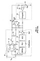
- Fig. 1 depicts a switched mode voltage regulator 10 having a conventional digital control circuit.
- the voltage regulator 10 comprises a buck converter topology to convert an input DC voltage V in to an output DC voltage V o applied to a resistive load 20 (R load ).
- the voltage regulator 10 includes a pair of power switches 12, 14 provided by MOSFET devices.
- the drain terminal of the high side power switch 12 is coupled to the input voltage V in
- the source terminal of the low side power switch 14 is connected to ground
- the source terminal of power switch 12 and the drain terminal of power switch 14 are coupled together to define a phase node.
- An output inductor 16 is coupled in series between the phase node and the terminal providing the output voltage V o
- a capacitor 18 is coupled in parallel with the resistive load R load .
- Respective drivers 22, 24 alternatingly drive the gate terminals of the power switches 12, 14.
- digital control circuit 30 controls operation of the drivers 22, 24.
- the opening and closing of the power switches 12, 14 provides an intermediate voltage having a generally rectangular waveform at the phase node, and the filter formed by the output inductor 16 and capacitor 18 converts the rectangular waveform into a substantially DC output voltage V o .
- the digital control circuit 30 receives a feedback signal from the output portion of the voltage regulator 10. As shown in Fig. 1, the feedback signal corresponds to the output voltage V o , though it should be appreciated that the feedback signal could alternatively (or additionally) correspond to the output current drawn by the resistive load R load or a combination thereof.
- the feedback path may further include a voltage divider provided by resistors 26, 28 to reduce the detected output voltage V o to a representative voltage level.
- the digital control circuit 30 provides a pulse width modulated waveform having a duty cycle controlled to regulate the output voltage V o (or output current) at a desired level.
- the exemplary voltage regulator 10 is illustrated as having a buck converter topology, it should be understood that the use of feedback loop control of the voltage regulator 10 using the digital control circuit 30 is equally applicable to other known voltage regulator topologies, such as boost and buck-boost converters in isolated or non-isolated configurations.
- the digital control circuit 30 includes subtractor 32, analog-to-digital converter (ADC) 34, digital filter 36, and digital pulse width modulator (DPWM) 38.
- the subtractor 32 receives as inputs the feedback signal (i.e., output voltage V o ) and a voltage reference (Ref) and provides an analog voltage error signal (Ref - V o ).
- the ADC 34 produces a digital representation of the voltage error signal.
- the digital filter 36 has a transfer function H(z) that transforms the voltage error signal to a digital output provided to the DPWM 38, which converts the digital output into a waveform having a proportional pulse width.
- the pulse-modulated waveform produced by the DPWM 38 is coupled to the gate terminals of the power switches 12, 14 through respective drivers 22, 24.
- the digital filter 36 may further comprise an infinite impulse response (IIR) filter having filter coefficients that may be selectively modified through a suitable input to thereby alter the performance characteristics of the digital filter.
- IIR infinite impulse response
- a second analog control loop 40 may be added, as shown in Fig. 2.
- the second control loop includes an amplifier 46 and an integrator 48.
- the second control loop 40 receives a feedback signal from the output portion of the voltage regulator 10 that corresponds to the output voltage V o .
- the feedback path may further include a voltage divider provided by resistors 42, 44 to reduce the detected output voltage V o to a representative voltage level.
- the feedback signal is provided to the inverting input terminal of the amplifier 46, and the non-inverting input terminal of the amplifier is coupled to a reference voltage.
- the amplifier 46 is selected to have lower bandwidth than the subtractor 32, thereby allowing greater accuracy with lower speed.
- the output of the amplifier 46 is provided to the integrator 48, which in turn provides an adjusting voltage to the subtractor 32 of the first loop through a suitable resistor.
- the integrator 48 assures that the error signal of the second control loop remains at zero during steady state operation.
- the first control loop provides fast transient response, while the second control loop provides high DC accuracy under steady state conditions.
- the digital control circuit includes a serial interface 52 that permits bidirectional data communication with a host system to receive data to control operation of the digital control circuit, and hence the voltage regulator, and to send status information back to the host system.
- a digital-to-analog converter 56 is coupled to the serial interface 52.
- a digital reference value provided from the host system via the serial interface 52 is converted by the digital-to-analog converter 56 to a reference voltage, that is in turn provided to the subtractor 32 for comparison to the representation of the output voltage V o .
- the serial interface 52 also communicates filter coefficient values to the digital filter 36 from the host system to thereby control the characteristics of the digital filter 36.
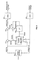
- the digital control circuit includes a first control loop that is substantially the same as the circuit described above with respect to Fig. 1.
- a second digital control loop is provided by analog-to-digital converter 58 and a digital filter circuit 70.
- the analog-to-digital converter 58 receives a feedback signal corresponding to the output voltage V o , reduced to a representative voltage level by voltage divider provided by resistors 62, 66.
- the analog-to-digital converter 58 is coupled to the serial interface 52 through a monitoring circuit 54. This way, the analog-to-digital converter 58 provides an accurate digital measurement of the output voltage, and this information may be communicated back to the host system through the monitoring circuit and the serial interface 52.
- the digital-to-analog converter 56 has a much lower resolution than the monitoring analog-to-digital converter 58.
- the resolution of the digital-to-analog converter 56 is selected to correspond to the specific supply voltage requirements of different loads R load .
- the analog-to-digital converter 34 has a small conversion range, but needs to be fast. Since there is always some residual ripple voltage present at the output of the regulator and the analog-to-digital converter 34 needs to have a fast response time, the ripple voltage cannot be filtered out since this would slow down the conversion process. The ripple therefore yields to an additional error signal in the first loop.
- the monitoring analog-to-digital converter 58 can run with a rather low sampling rate, but it should be accurate. To increase accuracy, the monitoring analog-to-digital converter 58 will include an anti-aliasing filter on its input which also will reduce the ripple voltage seen on the output of the regulator. This analog-to-digital converter 58 will therefore measure the true average value of the output and therefore has inherently better accuracy than the analog-to-digital converter 34.
- the digital filter circuit 70 further includes a digital comparator 76, a digital filter 74, and a variable resistor 72.
- the digital comparator 76 receives at a first input the digital reference value provided by the host system and at a second input the digital measurement of the output voltage V o , and produces a digital error value.
- the digital error value passes through the digital filter 74 and controls the setting of the variable resistor 72.
- the variable resistor 72 is part of the voltage divider defined by resistors 28 and 64. Accordingly, the representation of the output voltage V o provided to the subtractor 32 may be adjusted by controlling the setting of the variable resistor 72.
- Fig. 4 illustrates an embodiment of the digital filter circuit 70 in greater detail.
- the digital reference value will usually have less resolution than the monitoring output of the analog-to-digital converter 58.
- the reference signal has nine-bit resolution and the monitoring output has twelve-bit resolution.
- a digital comparator 82 is shown as having two twelve-bit inputs. The reference signal is multiplied by eight (i.e., by adding three trailing 0 bits) to scale it to the same width as the monitoring output.
- the digital comparator 82 compares the values and generates two outputs (i.e., A > B, and A ⁇ B).
- the two signals control an up/down counter 84 that acts as an integrator.
- the counter is incremented when the reference signal exceeds the monitoring output (A > B), and the counter is decremented when the monitoring output exceeds the reference signal (A ⁇ B).
- the counter 84 is selected such that it does not over-roll (i.e., the count does not go below zero and stops when it has reached its maximum). As shown in Fig. 4, the counter 84 has four-bit resolution with a range from zero to fifteen.
- a variable resistor is formed from field effect transistors 86 1 -86 4 , each having a source terminal coupled to ground and respective drain terminals coupled to resistors 88 2 -88 5 .
- Resistors 88 1 and 92 1 -92 4 are coupled together in series and between successive ones of the transistors 86 1 -86 4 .
- the gate terminals of the transistors 86 1 -86 4 are coupled to respective bits of the four-bit output of the counter 84.
- the counter 84 is clocked by a signal having a frequency that is substantially lower than the PWM frequency of the first digital control loop.
- the counter 84 is clocked by a signal having a frequency ranging from 100 to 1000 times lower than the PWM frequency. Accordingly, the second digital control loop is substantially slower than the first digital control loop, yet provides higher accuracy in view of the larger resolution of the monitoring analog-to-digital converter 58.
- the digital comparator 82 and the counter 84 are simple digital circuits, it is relatively easy to implement these circuits within a single digital control circuit containing both digital control loops.
- a drawback of this embodiment is that the digital filter 74 still acts on an analog circuit, i.e., the variable resistor 72. Thus, the digital correction value is converted back into an analog signal before acting upon the first digital control loop. It would therefore be further advantageous to have a control circuit that can be implemented using entirely digital circuitry.
- a switched mode voltage regulator having a digital double-loop control circuit is illustrated in accordance with a second embodiment of the invention.
- This embodiment differs from the preceding embodiment by including a digital filter circuit 100 having a digital comparator 102, a digital filter 104, and adder 106.
- the digital comparator 102 receives at a first input the digital reference value provided by the host system and at a second input the digital measurement of the output voltage V o , and produces a digital error value.
- the digital error value passes through the digital filter 104 and provides a digital value to the adder 106.
- the adder combines the digital reference value with the filtered digital value to produce an adjusted digital reference value.
- the adjusted digital reference value is provided to digital-to-analog converter 56, which converts the digital reference value to a reference voltage that is in turn provided to the subtractor 32 for comparison to the representation of the output voltage V o .
- the digital filter 104 modifies the reference value directly instead of using the resistor divider of the first control loop.
- the digital filter circuit 100 is adapted to virtually increase the resolution of the reference digital-to-analog converter 56. Moreover, the digital filter circuit 100 takes advantage of the fact that the first digital control loop has a low pass filter characteristic. In particular, if the digital reference value can be switched up and down by one count fast enough, then the first digital control loop will average the switching reference value and present an average reference value at the output of the reference digital-to-analog converter 56.
- Fig. 6 shows the digital filter circuit 100 of Fig. 5 in greater detail.
- the digital filter circuit includes a phase accumulator that provides dithering of the digital reference value.
- the digital filter circuit is further illustrated as including counter 112, adders 114, 116, 120, and phase converter 118.
- digital comparator 102 compares the monitored and referenced values and generates two outputs (i.e., A > B, and A ⁇ B).
- the two signals control an up/down counter 112 that acts as an integrator.
- the counter is incremented when the reference signal exceeds the monitoring output (A > B), and the counter is decremented when the monitoring output exceeds the reference signal (A ⁇ B).
- the counter 112 generates a six-bit digital error value that is divided such that the most significant two bits are provided to the adder 114 and the least significant four bits are provided to the adder 120. These least significant bits are considered to be the fractional part of the correction signal and are dithered over time by the phase register 118, which stores a continuous sum of the four-bit error values.
- the adder 120 which combined with the phase register 118 provides a phase accumulator in which the lower four bits of the error value are added to the phase value, is in turn fed back to the phase register. Whenever the adder 120 overflows, it produces a carry bit that is provided to adder 116. By adding the carry from the digital error value produced by adder 114, the adder 116 results in dithering of the fractional part of the digital error value E(5:0).
- the average value of the dithered reference can be set in increments ranging from 0, 1/16, 2/16.... 15/16, ... 3 14/16, 3 15/16, etc.
- the resolution of the digital-to-analog converter 56 resolution can be programmed in fractional amounts to permit controlling of the output voltage of the first loop in a more accurate way without requiring a digital-to-analog converter having high resolution.
Landscapes
- Engineering & Computer Science (AREA)
- Theoretical Computer Science (AREA)
- Power Engineering (AREA)
- General Engineering & Computer Science (AREA)
- Software Systems (AREA)
- Physics & Mathematics (AREA)
- General Physics & Mathematics (AREA)
- Computer Security & Cryptography (AREA)
- Quality & Reliability (AREA)
- Dc-Dc Converters (AREA)
- Feedback Control In General (AREA)
Applications Claiming Priority (1)
| Application Number | Priority Date | Filing Date | Title |
|---|---|---|---|
| US11/084,766 US7141956B2 (en) | 2005-03-18 | 2005-03-18 | Digital output voltage regulation circuit having first control loop for high speed and second control loop for high accuracy |
Publications (3)
| Publication Number | Publication Date |
|---|---|
| EP1703624A2 true EP1703624A2 (de) | 2006-09-20 |
| EP1703624A3 EP1703624A3 (de) | 2011-03-09 |
| EP1703624B1 EP1703624B1 (de) | 2015-07-15 |
Family
ID=36607479
Family Applications (1)
| Application Number | Title | Priority Date | Filing Date |
|---|---|---|---|
| EP05026905.9A Expired - Lifetime EP1703624B1 (de) | 2005-03-18 | 2005-12-08 | Digitale doppelschleifige Ausgangsspannungsregelung |
Country Status (4)
| Country | Link |
|---|---|
| US (2) | US7141956B2 (de) |
| EP (1) | EP1703624B1 (de) |
| KR (1) | KR100779785B1 (de) |
| CN (1) | CN100465823C (de) |
Cited By (3)
| Publication number | Priority date | Publication date | Assignee | Title |
|---|---|---|---|---|
| WO2007108974A3 (en) * | 2006-03-16 | 2008-01-10 | Analog Devices Inc | Multi-path digital power supply controller |
| WO2008097720A2 (en) | 2007-02-06 | 2008-08-14 | Power-One, Inc. | Digital double-loop output voltage regulation |
| WO2018060990A1 (en) * | 2016-09-28 | 2018-04-05 | B. G. Negev Technologies And Applications Ltd., At Ben-Gurion University | Digital average current-mode control voltage regulator and a method for tuning compensation coefficients thereof |
Families Citing this family (65)
| Publication number | Priority date | Publication date | Assignee | Title |
|---|---|---|---|---|
| US8008901B2 (en) * | 2006-02-28 | 2011-08-30 | Infineon Technologies Austria Ag | Regulated power supply with multiple regulators sharing the total current supplied to a load |
| US6949916B2 (en) * | 2002-11-12 | 2005-09-27 | Power-One Limited | System and method for controlling a point-of-load regulator |
| US7394445B2 (en) * | 2002-11-12 | 2008-07-01 | Power-One, Inc. | Digital power manager for controlling and monitoring an array of point-of-load regulators |
| US7456617B2 (en) | 2002-11-13 | 2008-11-25 | Power-One, Inc. | System for controlling and monitoring an array of point-of-load regulators by a host |
| US7882372B2 (en) | 2002-12-21 | 2011-02-01 | Power-One, Inc. | Method and system for controlling and monitoring an array of point-of-load regulators |
| US7673157B2 (en) | 2002-12-21 | 2010-03-02 | Power-One, Inc. | Method and system for controlling a mixed array of point-of-load regulators through a bus translator |
| US7249267B2 (en) | 2002-12-21 | 2007-07-24 | Power-One, Inc. | Method and system for communicating filter compensation coefficients for a digital power control system |
| US7743266B2 (en) | 2002-12-21 | 2010-06-22 | Power-One, Inc. | Method and system for optimizing filter compensation coefficients for a digital power control system |
| US7836322B2 (en) | 2002-12-21 | 2010-11-16 | Power-One, Inc. | System for controlling an array of point-of-load regulators and auxiliary devices |
| US7266709B2 (en) | 2002-12-21 | 2007-09-04 | Power-One, Inc. | Method and system for controlling an array of point-of-load regulators and auxiliary devices |
| US7737961B2 (en) | 2002-12-21 | 2010-06-15 | Power-One, Inc. | Method and system for controlling and monitoring an array of point-of-load regulators |
| US7373527B2 (en) | 2002-12-23 | 2008-05-13 | Power-One, Inc. | System and method for interleaving point-of-load regulators |
| US7710092B2 (en) * | 2003-02-10 | 2010-05-04 | Power-One, Inc. | Self tracking ADC for digital power supply control systems |
| US7080265B2 (en) | 2003-03-14 | 2006-07-18 | Power-One, Inc. | Voltage set point control scheme |
| US7372682B2 (en) | 2004-02-12 | 2008-05-13 | Power-One, Inc. | System and method for managing fault in a power system |
| US7141956B2 (en) * | 2005-03-18 | 2006-11-28 | Power-One, Inc. | Digital output voltage regulation circuit having first control loop for high speed and second control loop for high accuracy |
| US7323855B2 (en) * | 2005-03-31 | 2008-01-29 | Silicon Laboratories Inc. | Digital pulse width modulated power supply with variable LSB |
| US7501801B2 (en) * | 2005-06-30 | 2009-03-10 | Potentia Semiconductor Inc. | Power supply output voltage trimming |
| US8294441B2 (en) * | 2006-11-13 | 2012-10-23 | Decicon, Inc. | Fast low dropout voltage regulator circuit |
| US8304931B2 (en) | 2006-12-18 | 2012-11-06 | Decicon, Inc. | Configurable power supply integrated circuit |
| TW200830676A (en) * | 2007-01-03 | 2008-07-16 | Richtek Techohnology Corp | Digital compensator improving the voltage output function of switching power supply and method of designing the same |
| US8004111B2 (en) * | 2007-01-19 | 2011-08-23 | Astec International Limited | DC-DC switching cell modules for on-board power systems |
| KR101117416B1 (ko) * | 2007-02-06 | 2012-02-29 | 파워-원 인코포레이티드 | 디지털 이중-루프 출력 전압 조정 |
| US8274265B1 (en) | 2007-02-28 | 2012-09-25 | Netlogic Microsystems, Inc. | Multi-phase power system with redundancy |
| TW200847593A (en) * | 2007-05-18 | 2008-12-01 | Richtek Techohnology Corp | Digital voltage transformer and its control method |
| US7705577B2 (en) * | 2007-05-30 | 2010-04-27 | Virginia Tech Intellectual Properties, Inc. | Digital power supply control |
| US7570035B2 (en) * | 2007-08-01 | 2009-08-04 | Zerog Wireless, Inc. | Voltage regulator with a hybrid control loop |
| US7834613B2 (en) | 2007-10-30 | 2010-11-16 | Power-One, Inc. | Isolated current to voltage, voltage to voltage converter |
| US8305061B1 (en) * | 2008-06-04 | 2012-11-06 | National Semiconductor Corporation | Apparatus and method for digitally controlled buck-boost switching regulator |
| DE102009013897A1 (de) | 2009-03-19 | 2010-09-23 | Tridonicatco Gmbh & Co. Kg | Schaltung und Beleuchtungssystem zum Dimmen eines Leuchtmittels |
| KR101008432B1 (ko) | 2009-04-28 | 2011-01-14 | 삼성전기주식회사 | 디지털 디밍 led 구동 회로 |
| US8749213B2 (en) * | 2009-06-09 | 2014-06-10 | Silergy Technology | Mixed mode control for switching regulator with fast transient responses |
| TWI434494B (zh) * | 2009-10-12 | 2014-04-11 | Richtek Technology Corp | 具適應性電壓位置控制之電源轉換器控制電路及其控制方法 |
| CN102044966B (zh) * | 2009-10-26 | 2013-01-09 | 立锜科技股份有限公司 | 具有自适应电压位置控制的电源转换器控制电路及其控制方法 |
| KR101291344B1 (ko) | 2011-10-28 | 2013-07-30 | 숭실대학교산학협력단 | 스위치 모드 전원 제어장치 |
| EP2642650A1 (de) * | 2012-03-19 | 2013-09-25 | Zentrum Mikroelektronik Dresden AG | Stromwandler mit gemittelter Strombegrenzung |
| US9071136B2 (en) | 2012-03-30 | 2015-06-30 | Qualcomm Incorporated | System and method for suppression of peaking in an external LC filter of a buck regulator |
| US9389628B2 (en) | 2012-04-20 | 2016-07-12 | Intel Deutschland Gmbh | Digitally controlled buck-boost regulator having a custom mapping controller |
| KR101319989B1 (ko) * | 2012-04-25 | 2013-10-18 | 한국에너지기술연구원 | 복수의 전력변환모듈을 제어하는 장치 및 방법과, 전력량 불균형 분석 장치 및 방법 |
| US9136760B2 (en) | 2012-06-27 | 2015-09-15 | Analog Devices Global | Digital switched mode voltage regulator |
| US9231463B2 (en) * | 2012-08-06 | 2016-01-05 | Peter Oaklander | Noise resistant regulator including an encoded control signal |
| US8937468B2 (en) * | 2012-08-13 | 2015-01-20 | Northrop Grumman Systems Corporation | Power supply systems and methods |
| US9423807B2 (en) * | 2013-03-06 | 2016-08-23 | Qualcomm Incorporated | Switching power converter |
| WO2014142842A1 (en) * | 2013-03-13 | 2014-09-18 | Schneider Electric USA, Inc. | Supply regulation circuit with energy efficient digital control |
| US9000736B2 (en) * | 2013-05-03 | 2015-04-07 | Cooper Technologies Company | Power factor correction algorithm for arbitrary input waveform |
| US9190901B2 (en) | 2013-05-03 | 2015-11-17 | Cooper Technologies Company | Bridgeless boost power factor correction circuit for constant current input |
| US9214855B2 (en) | 2013-05-03 | 2015-12-15 | Cooper Technologies Company | Active power factor correction circuit for a constant current power converter |
| US9548794B2 (en) | 2013-05-03 | 2017-01-17 | Cooper Technologies Company | Power factor correction for constant current input with power line communication |
| US9209703B2 (en) * | 2013-08-14 | 2015-12-08 | Stmicroelectronics S.R.L. | Control device for a rectifier of a switching converter |
| CN103616556B (zh) * | 2013-11-22 | 2017-01-18 | 矽力杰半导体技术(杭州)有限公司 | 用于同步降压型变换器的过零检测电路及检测方法 |
| CN103869862A (zh) * | 2014-03-14 | 2014-06-18 | 北京理工大学 | 一种用于超声检测仪器脉冲激励电路供电的宽范围输出稳压电源方案 |
| US9397566B2 (en) * | 2014-03-20 | 2016-07-19 | Intel Corporation | Master-slave digital voltage regulators |
| JP6370929B2 (ja) * | 2014-05-22 | 2018-08-08 | テキサス インスツルメンツ インコーポレイテッド | デュアルカウンタデジタル積分器を備えるdc‐dcコンバータコントローラ装置 |
| DE102014210660A1 (de) * | 2014-06-04 | 2015-12-17 | Siemens Aktiengesellschaft | Eingangsschaltung zur Verarbeitung eines analogen Eingangssignals in Form eines analogen Messsignals mit einem aufmodulierten Zusatzsignal und Verfahren zum Betrieb einer solchen Eingangsschaltung |
| KR102204678B1 (ko) | 2014-12-11 | 2021-01-20 | 삼성전자주식회사 | 인버터 증폭기 기반의 이중 루프 레귤레이터 및 그에 따른 전압 레귤레이팅 방법 |
| CN104899636A (zh) * | 2015-05-12 | 2015-09-09 | 广州中大微电子有限公司 | 一种应用于rfid阅读器全芯片的供电管理装置及方法 |
| US9614506B1 (en) * | 2015-12-03 | 2017-04-04 | Texas Instruments Incorporated | Digital pre-compensation for voltage slewing in a power converter |
| US9843257B2 (en) * | 2016-02-05 | 2017-12-12 | Infineon Technologies Austria Ag | Set point independent regulation of a switched mode power converter |
| CN105573391B (zh) * | 2016-03-04 | 2017-06-30 | 哈尔滨工业大学深圳研究生院 | 太阳阵模拟器的开路电压控制电路及其开路电压控制方法 |
| US10404172B1 (en) * | 2018-06-29 | 2019-09-03 | Apple Inc. | Transient booster for zero static loadline switching regulator |
| JP7166179B2 (ja) * | 2019-01-25 | 2022-11-07 | 株式会社東芝 | 電源回路 |
| US11469666B2 (en) * | 2019-10-01 | 2022-10-11 | Allegro Microsystems, Llc | Converter digital control circuit with adaptive feedforward compensation |
| KR102921043B1 (ko) * | 2021-03-03 | 2026-02-03 | 삼성전자주식회사 | 데드 타임 컨트롤러 및 이를 포함하는 dc-dc 컨버터 |
| CN113485200A (zh) * | 2021-07-30 | 2021-10-08 | 蔚来汽车科技(安徽)有限公司 | 用于电子器件的控制装置、方法、移动装备和存储介质 |
| CN113556043B (zh) * | 2021-09-17 | 2021-12-24 | 四川英杰电气股份有限公司 | 一种谐振变换器的调频控制电路及其控制方法 |
Family Cites Families (193)
| Publication number | Priority date | Publication date | Assignee | Title |
|---|---|---|---|---|
| US429581A (en) * | 1890-06-03 | parmelee | ||
| US3660672A (en) * | 1971-02-25 | 1972-05-02 | Pioneer Magnetics Inc | Power supply dual output |
| GB1536046A (en) * | 1976-06-30 | 1978-12-20 | Ibm | Data processing system power control |
| US4194147A (en) * | 1977-12-05 | 1980-03-18 | Burr-Brown Research Corporation | Parallel connected switching regulator system |
| DE2904786C2 (de) | 1979-02-08 | 1981-02-19 | Siemens Ag, 1000 Berlin Und 8000 Muenchen | Verfahren zur Regelung von Wechselrichtern im Parallelbetrieb und Schaltungsanordnungen zur Durchführung des Verfahrens |
| US4335445A (en) * | 1979-02-26 | 1982-06-15 | Kepco, Inc. | System for interfacing computers with programmable power supplies |
| JPS5790721A (en) * | 1980-11-28 | 1982-06-05 | Toshiba Corp | Tap switching controller |
| US4451773A (en) * | 1982-04-02 | 1984-05-29 | Bell Telephone Laboratories, Incorporated | Rectifier control system for a DC power plant system |
| DE3369778D1 (en) * | 1982-06-04 | 1987-03-12 | Nippon Chemicon | Power supply device |
| JPS59108121A (ja) * | 1982-12-14 | 1984-06-22 | Tokyo Denshi Kogyo Kk | 交流電圧調整装置 |
| US4538073A (en) * | 1983-05-09 | 1985-08-27 | Convergent Technologies, Inc. | Modular power supply system |
| US4622627A (en) * | 1984-02-16 | 1986-11-11 | Theta-J Corporation | Switching electrical power supply utilizing miniature inductors integrally in a PCB |
| US4677566A (en) * | 1984-10-18 | 1987-06-30 | Burroughs Corporation | Power control network for multiple digital modules |
| US4654769A (en) * | 1984-11-02 | 1987-03-31 | California Institute Of Technology | Transformerless dc-to-dc converters with large conversion ratios |
| US4616142A (en) * | 1984-12-31 | 1986-10-07 | Sundstrand Corporation | Method of operating parallel-connected semiconductor switch elements |
| US4630187A (en) | 1985-09-09 | 1986-12-16 | Sperry Corporation | Power converter with duty ratio quantization |
| SU1359874A1 (ru) | 1985-10-14 | 1987-12-15 | Специальное Конструкторское Бюро Телевизионной Аппаратуры Симферопольского Производственного Объединения "Фотон" | Преобразователь посто нного напр жени |
| CA1295014C (en) | 1986-08-01 | 1992-01-28 | Christopher Paul Henze | Digitally controlled a.c. to d.c. power conditioner that draws sinusoidal input current |
| US4761725A (en) | 1986-08-01 | 1988-08-02 | Unisys Corporation | Digitally controlled A.C. to D.C. power conditioner |
| US4766364A (en) | 1987-11-04 | 1988-08-23 | International Business Machines Corporation | Parallel power systems |
| US5168208A (en) | 1988-05-09 | 1992-12-01 | Onan Corporation | Microprocessor based integrated generator set controller apparatus and method |
| US4988942A (en) | 1988-11-08 | 1991-01-29 | Spectra-Physics, Inc. | Switched resistor regulator control when transfer function includes discontinuity |
| US5053920A (en) * | 1989-06-09 | 1991-10-01 | Digital Equipment Corporation | Integrated power conversion |
| US4940930A (en) | 1989-09-07 | 1990-07-10 | Honeywell Incorporated | Digitally controlled current source |
| US5004972A (en) | 1989-12-26 | 1991-04-02 | Honeywell Inc. | Integrated power level control and on/off function circuit |
| FR2656932B1 (fr) | 1990-01-09 | 1992-05-07 | Sgs Thomson Microelectronics | Circuit de mesure du courant dans un transistor mos de puissance. |
| US5270904A (en) | 1990-05-02 | 1993-12-14 | Zdzislaw Gulczynski | Switching power apparatus with 3-state driver |
| RU1814177C (ru) | 1990-11-05 | 1993-05-07 | Киевский Политехнический Институт Им.50-Летия Великой Октябрьской Социалистической Революции | Преобразователь напр жени |
| US5073848A (en) * | 1990-11-21 | 1991-12-17 | General Electric Company | Power distribution system |
| US5117430A (en) * | 1991-02-08 | 1992-05-26 | International Business Machines Corporation | Apparatus and method for communicating between nodes in a network |
| US5079498A (en) * | 1991-03-26 | 1992-01-07 | Vickers Systems Limited | Digital pulse-width-modulation generator for current control |
| US6115441A (en) * | 1991-07-09 | 2000-09-05 | Dallas Semiconductor Corporation | Temperature detector systems and methods |
| DE4122945A1 (de) * | 1991-07-11 | 1993-01-14 | Philips Patentverwaltung | Mikroprozessorgesteuerter gleichspannungswandler |
| US5229699A (en) * | 1991-10-15 | 1993-07-20 | Industrial Technology Research Institute | Method and an apparatus for PID controller tuning |
| US5481140A (en) * | 1992-03-10 | 1996-01-02 | Mitsubishi Denki Kabushiki Kaisha | Demand control apparatus and power distribution control system |
| GB9205995D0 (en) | 1992-03-19 | 1992-04-29 | Astec Int Ltd | A power supply |
| US5426425A (en) | 1992-10-07 | 1995-06-20 | Wescom, Inc. | Intelligent locator system with multiple bits represented in each pulse |
| US5377090A (en) * | 1993-01-19 | 1994-12-27 | Martin Marietta Corporation | Pulsed power converter with multiple output voltages |
| JP3191275B2 (ja) * | 1993-02-22 | 2001-07-23 | 横河電機株式会社 | スイッチング電源装置 |
| US5481178A (en) | 1993-03-23 | 1996-01-02 | Linear Technology Corporation | Control circuit and method for maintaining high efficiency over broad current ranges in a switching regulator circuit |
| US5489904A (en) * | 1993-09-28 | 1996-02-06 | The Regents Of The University Of California | Analog current mode analog/digital converter |
| JPH07143741A (ja) * | 1993-11-15 | 1995-06-02 | Hitachi Ltd | スイッチング電源 |
| JP2833460B2 (ja) | 1993-12-27 | 1998-12-09 | 株式会社日立製作所 | 電源システム |
| US6121760A (en) | 1994-03-17 | 2000-09-19 | Texas Instruments Incorporated | Turn-on controller for switch-mode regulator |
| US5532577A (en) * | 1994-04-01 | 1996-07-02 | Maxim Integrated Products, Inc. | Method and apparatus for multiple output regulation in a step-down switching regulator |
| US5627460A (en) * | 1994-12-28 | 1997-05-06 | Unitrode Corporation | DC/DC converter having a bootstrapped high side driver |
| US5949226A (en) * | 1995-04-10 | 1999-09-07 | Kabushiki Kaisha Toyoda Jidoshokki Seisakush | DC/DC converter with reduced power consumpton and improved efficiency |
| US5727208A (en) * | 1995-07-03 | 1998-03-10 | Dell U.S.A. L.P. | Method and apparatus for configuration of processor operating parameters |
| US5752047A (en) * | 1995-08-11 | 1998-05-12 | Mcdonnell Douglas Corporation | Modular solid state power controller with microcontroller |
| US5646509A (en) * | 1995-12-01 | 1997-07-08 | International Business Machines Corporation | Battery capacity test and electronic system utilizing same |
| US5631550A (en) | 1996-04-25 | 1997-05-20 | Lockheed Martin Tactical Defense Systems | Digital control for active power factor correction |
| US5675480A (en) * | 1996-05-29 | 1997-10-07 | Compaq Computer Corporation | Microprocessor control of parallel power supply systems |
| US5943227A (en) * | 1996-06-26 | 1999-08-24 | Fairchild Semiconductor Corporation | Programmable synchronous step down DC-DC converter controller |
| US5815018A (en) * | 1996-07-16 | 1998-09-29 | Systech Solutions, Inc. | Pulse modulator circuit for an illuminator system |
| JP3042423B2 (ja) * | 1996-09-30 | 2000-05-15 | 日本電気株式会社 | 直並列型a/d変換器 |
| US5929620A (en) | 1996-11-07 | 1999-07-27 | Linear Technology Corporation | Switching regulators having a synchronizable oscillator frequency with constant ramp amplitude |
| WO1998024247A1 (de) * | 1996-11-22 | 1998-06-04 | Siemens Aktiengesellschaft | Verfahren und routing-system zur dynamischen verkehrslenkung in einem kommunikationsnetz |
| US5847950A (en) * | 1997-02-19 | 1998-12-08 | Electronic Measurements, Inc. | Control system for a power supply |
| US5889392A (en) | 1997-03-06 | 1999-03-30 | Maxim Integrated Products, Inc. | Switch-mode regulators and methods providing transient response speed-up |
| US5892933A (en) * | 1997-03-31 | 1999-04-06 | Compaq Computer Corp. | Digital bus |
| US5872984A (en) * | 1997-04-01 | 1999-02-16 | International Business Machines Corporation | Uninterruptible power supply providing continuous power mainstore function for a computer system |
| US5946495A (en) * | 1997-04-08 | 1999-08-31 | Compaq Computer Corp. | Data communication circuit for controlling data communication between redundant power supplies and peripheral devices |
| US5933453A (en) | 1997-04-29 | 1999-08-03 | Hewlett-Packard Company | Delta-sigma pulse width modulator control circuit |
| US5905370A (en) * | 1997-05-06 | 1999-05-18 | Fairchild Semiconductor Corporation | Programmable step down DC-DC converter controller |
| US5883797A (en) * | 1997-06-30 | 1999-03-16 | Power Trends, Inc. | Parallel path power supply |
| US5917719A (en) * | 1997-08-11 | 1999-06-29 | Power Ten, Inc. | Internally programmable modular power supply and method |
| US5935252A (en) * | 1997-08-18 | 1999-08-10 | International Business Machines Corporation | Apparatus and method for determining and setting system device configuration relating to power and cooling using VPD circuits associated with system devices |
| US6000042A (en) | 1997-08-25 | 1999-12-07 | 3Com Corporation | Fault detection on a dual supply system for a universal serial bus system |
| US5870296A (en) | 1997-10-14 | 1999-02-09 | Maxim Integrated Products, Inc. | Dual interleaved DC to DC switching circuits realized in an integrated circuit |
| US5936565A (en) * | 1997-12-10 | 1999-08-10 | Nortel Networks Corporation | Digitally controlled duty cycle integration |
| US6079026A (en) * | 1997-12-11 | 2000-06-20 | International Business Machines Corporation | Uninterruptible memory backup power supply system using threshold value of energy in the backup batteries for control of switching from AC to DC output |
| US5990669A (en) * | 1997-12-15 | 1999-11-23 | Dell Usa, L.P. | Voltage supply regulation using master/slave timer circuit modulation |
| JP3702091B2 (ja) * | 1998-03-31 | 2005-10-05 | 富士通株式会社 | 電源装置、および電源回路の制御方法 |
| JP3744680B2 (ja) * | 1998-03-31 | 2006-02-15 | 富士通株式会社 | 電源装置、および電源回路の制御方法 |
| FI107418B (fi) * | 1998-05-22 | 2001-07-31 | Muuntolaite Oy | Menetelmä ja laitteisto teholähdejärjestelmän ohjaamiseksi |
| US6199130B1 (en) * | 1998-06-04 | 2001-03-06 | International Business Machines Corporation | Concurrent maintenance for PCI based DASD subsystem with concurrent maintenance message being communicated between SPCN (system power control network) and I/O adapter using PCI bridge |
| US5929618A (en) * | 1998-06-04 | 1999-07-27 | Lucent Technologies Inc. | System and method for synchronizing and interleaving power modules |
| US6055163A (en) | 1998-08-26 | 2000-04-25 | Northrop Grumman Corporation | Communications processor remote host and multiple unit control devices and methods for micropower generation systems |
| US6177787B1 (en) | 1998-09-11 | 2001-01-23 | Linear Technology Corporation | Circuits and methods for controlling timing and slope compensation in switching regulators |
| US6304823B1 (en) | 1998-09-16 | 2001-10-16 | Microchip Technology Incorporated | Microprocessor power supply system including a programmable power supply and a programmable brownout detector |
| US6268716B1 (en) | 1998-10-30 | 2001-07-31 | Volterra Semiconductor Corporation | Digital voltage regulator using current control |
| DE19850125B4 (de) | 1998-10-30 | 2007-06-28 | Siemens Ag | Netzteil für Spannungsversorgung eines Busses |
| US6198261B1 (en) | 1998-10-30 | 2001-03-06 | Volterra Semiconductor Corporation | Method and apparatus for control of a power transistor in a digital voltage regulator |
| US6100676A (en) | 1998-10-30 | 2000-08-08 | Volterra Semiconductor Corporation | Method and apparatus for digital voltage regulation |
| US6181029B1 (en) * | 1998-11-06 | 2001-01-30 | International Business Machines Corporation | Method of controlling battery back-up for multiple power supplies |
| US6163178A (en) | 1998-12-28 | 2000-12-19 | Rambus Incorporated | Impedance controlled output driver |
| US6021059A (en) | 1998-12-31 | 2000-02-01 | Honeywell Inc. | Integrated synchronous rectifier for power supplies |
| WO2000044098A1 (en) * | 1999-01-19 | 2000-07-27 | Steensgaard Madsen Jesper | Residue-compensating a / d converter |
| US6137280A (en) | 1999-01-22 | 2000-10-24 | Science Applications International Corporation | Universal power manager with variable buck/boost converter |
| US6184659B1 (en) | 1999-02-16 | 2001-02-06 | Microchip Technology Incorporated | Microcontroller with integral switch mode power supply controller |
| US6355990B1 (en) | 1999-03-24 | 2002-03-12 | Rockwell Collins, Inc. | Power distribution system and method |
| US6111396A (en) | 1999-04-15 | 2000-08-29 | Vanguard International Semiconductor Corporation | Any value, temperature independent, voltage reference utilizing band gap voltage reference and cascode current mirror circuits |
| US6917186B2 (en) | 2000-04-24 | 2005-07-12 | S & C Electric Co. | Monitoring and control for power electronic system |
| JP3644531B2 (ja) | 1999-07-06 | 2005-04-27 | 富士電機機器制御株式会社 | オンディレイ補償用アームオン検出回路 |
| US6057607A (en) * | 1999-07-16 | 2000-05-02 | Semtech Corporation | Method and apparatus for voltage regulation in multi-output switched mode power supplies |
| US6191566B1 (en) * | 1999-08-26 | 2001-02-20 | Lucent Technologies Inc. | Board mountable power supply module with multi-function control pin |
| US6294954B1 (en) | 1999-09-23 | 2001-09-25 | Audiologic, Incorporated | Adaptive dead time control for switching circuits |
| US6157093A (en) | 1999-09-27 | 2000-12-05 | Philips Electronics North America Corporation | Modular master-slave power supply controller |
| US6211579B1 (en) * | 1999-09-29 | 2001-04-03 | Lucent Technologies, Inc. | Multiple output converter having a low power dissipation cross regulation compensation circuit |
| US6392577B1 (en) * | 1999-10-05 | 2002-05-21 | Stmicroelectronics, Inc. | System and method for regulating an alternator |
| US6465993B1 (en) | 1999-11-01 | 2002-10-15 | John Clarkin | Voltage regulation employing a composite feedback signal |
| US6208127B1 (en) * | 1999-11-02 | 2001-03-27 | Maxim Integrated Products, Inc. | Methods and apparatus to predictably change the output voltage of regulators |
| EP1259866A2 (de) * | 2000-01-27 | 2002-11-27 | Primarion, Inc. | Vorrichtung zum herstellen von geregelter versorgungsspannung an einer integrierten schaltung |
| US6396169B1 (en) * | 2000-02-29 | 2002-05-28 | 3Com Corporation | Intelligent power supply control for electronic systems requiring multiple voltages |
| US6385024B1 (en) * | 2000-03-07 | 2002-05-07 | Ss8 Networks, Inc. | System and method for monitoring current consumption from current share components |
| US6246219B1 (en) | 2000-03-24 | 2001-06-12 | The Boeing Company | String switching apparatus and associated method for controllably connecting the output of a solar array string to a respective power bus |
| US6291975B1 (en) | 2000-03-27 | 2001-09-18 | Rockwell Collins | Method and system for efficiently regulating power supply voltages with reduced propagation of power transients capable of communicating information |
| US6150803A (en) | 2000-03-28 | 2000-11-21 | Linear Technology Corporation | Dual input, single output power supply |
| US6373334B1 (en) | 2000-06-12 | 2002-04-16 | Cirrus Logic, Inc. | Real time correction of a digital PWM amplifier |
| US20010052862A1 (en) | 2000-06-20 | 2001-12-20 | Koninklijke Philips Electronics N.V. | Security system simulates patterns of usage of appliances |
| US6249111B1 (en) | 2000-06-22 | 2001-06-19 | Intel Corporation | Dual drive buck regulator |
| US6465909B1 (en) | 2000-07-31 | 2002-10-15 | Linear Technology Corporation | Circuits and methods for controlling load sharing by multiple power supplies |
| US6396250B1 (en) * | 2000-08-31 | 2002-05-28 | Texas Instruments Incorporated | Control method to reduce body diode conduction and reverse recovery losses |
| IT1318879B1 (it) * | 2000-09-19 | 2003-09-10 | St Microelectronics Srl | Dispositivo controllore di tensione/corrente, in particolare perregolatori switching interleaving. |
| US6320768B1 (en) | 2000-10-06 | 2001-11-20 | Texas Instruments Incorporated | Power supply pulse width modulation (PWM) control system |
| US7007176B2 (en) * | 2000-10-10 | 2006-02-28 | Primarion, Inc. | System and method for highly phased power regulation using adaptive compensation control |
| AU2002211583A1 (en) * | 2000-10-10 | 2002-04-22 | Primarion, Inc. | System and method for highly phased power regulation |
| EP1325547A2 (de) | 2000-10-13 | 2003-07-09 | Primarion, Inc. | Verfahren und vorrichtung zur hochphasenleistungsregelung |
| IT1319007B1 (it) * | 2000-10-16 | 2003-09-19 | St Microelectronics Srl | Sistema di gestione di una pluralita' di moduli vrm e relativo metododi sincronizzazione |
| US6654264B2 (en) | 2000-12-13 | 2003-11-25 | Intel Corporation | System for providing a regulated voltage with high current capability and low quiescent current |
| EP1215808B1 (de) * | 2000-12-13 | 2011-05-11 | Semiconductor Components Industries, LLC | Stromversorgungsschaltung und dazugehöriges Verfahren zur Entmagnetisierungsdetektion der Stromversorgung |
| TW554605B (en) | 2000-12-20 | 2003-09-21 | Delta Electronics Inc | Output voltage adjustable electrical power switcher |
| US7092041B2 (en) | 2000-12-20 | 2006-08-15 | Thomson Licensing | I2C bus control for isolating selected IC's for fast I2C bus communication |
| US6421259B1 (en) * | 2000-12-28 | 2002-07-16 | International Business Machines Corporation | Modular DC distribution system for providing flexible power conversion scalability within a power backplane between an AC source and low voltage DC outputs |
| US6411071B1 (en) | 2000-12-29 | 2002-06-25 | Volterra Semiconductor Corporation | Lag compensating controller having an improved transient response |
| US6828765B1 (en) | 2000-12-29 | 2004-12-07 | Volterra Semiconductor Corporation | Method and computer program product for improved transient response |
| US6686831B2 (en) | 2001-01-23 | 2004-02-03 | Invensys Systems, Inc. | Variable power control for process control instruments |
| US6947273B2 (en) * | 2001-01-29 | 2005-09-20 | Primarion, Inc. | Power, ground, and routing scheme for a microprocessor power regulator |
| US6965502B2 (en) * | 2001-03-21 | 2005-11-15 | Primarion, Inc. | System, device and method for providing voltage regulation to a microelectronic device |
| US6791302B2 (en) * | 2001-03-21 | 2004-09-14 | Primarion, Inc. | Methods and apparatus for open-loop enhanced control of power supply transients |
| US6975494B2 (en) | 2001-01-29 | 2005-12-13 | Primarion, Inc. | Method and apparatus for providing wideband power regulation to a microelectronic device |
| US6366069B1 (en) | 2001-02-01 | 2002-04-02 | Intel Corporation | Hysteretic-mode multi-phase switching regulator |
| US6800957B2 (en) * | 2001-02-06 | 2004-10-05 | General Electric Company | Electronic distribution system for 36V automobiles |
| TW575949B (en) | 2001-02-06 | 2004-02-11 | Hitachi Ltd | Mixed integrated circuit device, its manufacturing method and electronic apparatus |
| US6400127B1 (en) | 2001-02-12 | 2002-06-04 | Philips Electronics North America Corporation | Dual mode pulse-width modulator for power control applications |
| TW556396B (en) * | 2001-03-22 | 2003-10-01 | Primarion Inc | Power regulation system, apparatus, and method for providing regulated power to a microelectronic device |
| EP1374394B1 (de) * | 2001-03-26 | 2006-05-31 | Harman International Industries, Incorporated | Pulsbreitemodulationsverstärker mit digitalem signalprozessor |
| US6731023B2 (en) * | 2001-03-29 | 2004-05-04 | Autoliv Asp, Inc. | Backup power supply for restraint control module |
| US20040225811A1 (en) | 2001-04-04 | 2004-11-11 | Fosler Ross M. | Digital addressable lighting interface bridge |
| US6476589B2 (en) | 2001-04-06 | 2002-11-05 | Linear Technology Corporation | Circuits and methods for synchronizing non-constant frequency switching regulators with a phase locked loop |
| US6411072B1 (en) | 2001-04-17 | 2002-06-25 | Honeywell International Inc. | PWM power supply with constant RMS output voltage control |
| US6469478B1 (en) | 2001-04-23 | 2002-10-22 | Artesyn Technologies, Inc. | Multiple output power supply including one regulated converter and at least one semi-regulated converter |
| US6816758B2 (en) | 2001-04-26 | 2004-11-09 | The Boeing Company | Programmable controller for remotely controlling input power through a switch to a load and an associated method of operation |
| US6621259B2 (en) * | 2001-05-30 | 2003-09-16 | Texas Instruments Incorporated | Current sense amplifier and method |
| US6788035B2 (en) * | 2001-06-12 | 2004-09-07 | Primarion, Inc. | Serial bus control method and apparatus for a microelectronic power regulation system |
| US6915440B2 (en) * | 2001-06-12 | 2005-07-05 | International Business Machines Corporation | Apparatus, program product and method of performing power fault analysis in a computer system |
| US6744243B2 (en) | 2001-06-28 | 2004-06-01 | Texas Instruments Incorporated | System and method for dynamically regulating a step down power supply |
| US6928560B1 (en) | 2001-09-28 | 2005-08-09 | Unisys Corporation | Distributed power control system |
| US6577258B2 (en) | 2001-10-01 | 2003-06-10 | Nokia Corporation | Adaptive sigma-delta data converter for mobile terminals |
| US6795009B2 (en) * | 2002-09-09 | 2004-09-21 | Primarion, Inc. | System and method for current handling in a digitally-controlled power converter |
| WO2003041238A2 (en) | 2001-11-05 | 2003-05-15 | Shakti Systems, Inc. | Monolithic battery charging device |
| CN2521825Y (zh) | 2001-11-20 | 2002-11-20 | 罗代云 | 一种新型的数字音频功率放大器 |
| US7554828B2 (en) | 2001-12-03 | 2009-06-30 | Igo, Inc. | Power converter with retractable cable system |
| US6903949B2 (en) | 2001-12-12 | 2005-06-07 | International Rectifier Corporation | Resonant converter with phase delay control |
| US6807070B2 (en) | 2001-12-12 | 2004-10-19 | International Rectifier Corporation | Resonant converter with phase delay control |
| US6717389B1 (en) | 2001-12-21 | 2004-04-06 | Unisys Corporation | Method and apparatus for current controlled transient reduction in a voltage regulator |
| US20030122429A1 (en) * | 2001-12-28 | 2003-07-03 | Zhang Kevin X. | Method and apparatus for providing multiple supply voltages for a processor |
| US6448745B1 (en) * | 2002-01-08 | 2002-09-10 | Dialog Semiconductor Gmbh | Converter with inductor and digital controlled timing |
| US6930893B2 (en) * | 2002-01-31 | 2005-08-16 | Vlt, Inc. | Factorized power architecture with point of load sine amplitude converters |
| US6975098B2 (en) | 2002-01-31 | 2005-12-13 | Vlt, Inc. | Factorized power architecture with point of load sine amplitude converters |
| JP4098533B2 (ja) * | 2002-02-28 | 2008-06-11 | Tdk株式会社 | スイッチング電源装置用制御回路及びこれを用いたスイッチング電源装置 |
| US6897636B2 (en) * | 2002-03-29 | 2005-05-24 | Intersil Americas Inc. | Method and circuit for scaling and balancing input and output currents in a multi-phase DC-DC converter using different input voltages |
| SE0201432D0 (sv) * | 2002-04-29 | 2002-05-13 | Emerson Energy Systems Ab | A Power supply system and apparatus |
| US6829547B2 (en) | 2002-04-29 | 2004-12-07 | Tektronix, Inc. | Measurement test instrument and associated voltage management system for accessory device |
| US6850426B2 (en) | 2002-04-30 | 2005-02-01 | Honeywell International Inc. | Synchronous and bi-directional variable frequency power conversion systems |
| KR200284495Y1 (ko) | 2002-05-10 | 2002-08-03 | 로보랜드(주) | 로봇용 서보모터 구동모듈 |
| US6693811B1 (en) | 2002-07-02 | 2004-02-17 | Tyco Electronics Power Systems, Inc. | Integrated controller, method of operation thereof and power supply employing the same |
| US6977492B2 (en) * | 2002-07-10 | 2005-12-20 | Marvell World Trade Ltd. | Output regulator |
| US6788033B2 (en) * | 2002-08-08 | 2004-09-07 | Vlt, Inc. | Buck-boost DC-DC switching power conversion |
| US6801027B2 (en) | 2002-09-26 | 2004-10-05 | Itt Manufacturing Enterprises, Inc. | Power conversion in variable load applications |
| US6949916B2 (en) * | 2002-11-12 | 2005-09-27 | Power-One Limited | System and method for controlling a point-of-load regulator |
| US7000125B2 (en) * | 2002-12-21 | 2006-02-14 | Power-One, Inc. | Method and system for controlling and monitoring an array of point-of-load regulators |
| US7049798B2 (en) * | 2002-11-13 | 2006-05-23 | Power-One, Inc. | System and method for communicating with a voltage regulator |
| US6979987B2 (en) * | 2002-11-14 | 2005-12-27 | Fyre Storm, Inc. | Method of regulating an output voltage of a power converter by sensing the output voltage during a first time interval and calculating a next current value in an inductor sufficient to bring the output voltage to a target voltage within a second time interval immediately following the first time interval and varying a duty cycle of a switch during the second time interval |
| US6833691B2 (en) | 2002-11-19 | 2004-12-21 | Power-One Limited | System and method for providing digital pulse width modulation |
| US6778414B2 (en) | 2002-12-20 | 2004-08-17 | The Boeing Company | Distributed system and methodology of electrical power regulation, conditioning and distribution on an aircraft |
| US6933709B2 (en) * | 2003-02-10 | 2005-08-23 | Power-One Limited | Digital control system and method for switched mode power supply |
| US7249267B2 (en) | 2002-12-21 | 2007-07-24 | Power-One, Inc. | Method and system for communicating filter compensation coefficients for a digital power control system |
| US7373527B2 (en) * | 2002-12-23 | 2008-05-13 | Power-One, Inc. | System and method for interleaving point-of-load regulators |
| US6771052B2 (en) * | 2003-01-03 | 2004-08-03 | Astec International Limited | Programmable multiple output DC-DC isolated power supply |
| TWI221534B (en) * | 2003-01-08 | 2004-10-01 | Aimtron Technology Corp | Current detection circuit for high speed driving stage |
| US7023672B2 (en) * | 2003-02-03 | 2006-04-04 | Primarion, Inc. | Digitally controlled voltage regulator |
| US6850046B2 (en) | 2003-02-10 | 2005-02-01 | Power-One Limited | Digital signal processor architecture optimized for controlling switched mode power supply |
| JP2004259951A (ja) | 2003-02-26 | 2004-09-16 | Renesas Technology Corp | 半導体装置 |
| US7080265B2 (en) | 2003-03-14 | 2006-07-18 | Power-One, Inc. | Voltage set point control scheme |
| US6936999B2 (en) * | 2003-03-14 | 2005-08-30 | Power-One Limited | System and method for controlling output-timing parameters of power converters |
| US6888339B1 (en) | 2003-04-03 | 2005-05-03 | Lockheed Martin Corporation | Bus voltage control using gated fixed energy pulses |
| US7506179B2 (en) | 2003-04-11 | 2009-03-17 | Zilker Labs, Inc. | Method and apparatus for improved DC power delivery management and configuration |
| JP3943524B2 (ja) * | 2003-05-14 | 2007-07-11 | 太陽誘電株式会社 | 電源装置 |
| US20050093594A1 (en) * | 2003-10-30 | 2005-05-05 | Infineon Technologies North America Corp. | Delay locked loop phase blender circuit |
| US7038437B2 (en) | 2003-12-31 | 2006-05-02 | Agilent Technologies, Inc. | Programmable power supply having digitally implemented slew rate controller |
| US7142140B2 (en) * | 2004-07-27 | 2006-11-28 | Silicon Laboratories Inc. | Auto scanning ADC for DPWM |
| US7141956B2 (en) * | 2005-03-18 | 2006-11-28 | Power-One, Inc. | Digital output voltage regulation circuit having first control loop for high speed and second control loop for high accuracy |
-
2005
- 2005-03-18 US US11/084,766 patent/US7141956B2/en not_active Expired - Lifetime
- 2005-12-08 EP EP05026905.9A patent/EP1703624B1/de not_active Expired - Lifetime
-
2006
- 2006-01-11 CN CNB2006100036738A patent/CN100465823C/zh not_active Expired - Lifetime
- 2006-01-13 KR KR1020060003954A patent/KR100779785B1/ko not_active Expired - Lifetime
- 2006-11-27 US US11/605,045 patent/US7394236B2/en not_active Expired - Lifetime
Non-Patent Citations (1)
| Title |
|---|
| "Digital current-mode controller for DC-DC converters", APPLIED POWER ELECTRONICS CONFERENCE AND EXPOSITION, vol. 2, 6 March 2005 (2005-03-06), pages 899 - 905 |
Cited By (5)
| Publication number | Priority date | Publication date | Assignee | Title |
|---|---|---|---|---|
| WO2007108974A3 (en) * | 2006-03-16 | 2008-01-10 | Analog Devices Inc | Multi-path digital power supply controller |
| WO2008097720A2 (en) | 2007-02-06 | 2008-08-14 | Power-One, Inc. | Digital double-loop output voltage regulation |
| EP2122831A4 (de) * | 2007-02-06 | 2012-02-15 | Power One Inc | Spannungsregulierung für digitale doppelschleifenausgänge |
| WO2018060990A1 (en) * | 2016-09-28 | 2018-04-05 | B. G. Negev Technologies And Applications Ltd., At Ben-Gurion University | Digital average current-mode control voltage regulator and a method for tuning compensation coefficients thereof |
| US10770969B2 (en) | 2016-09-28 | 2020-09-08 | B. G. Negev Technologies And Applications Ltd., At Ben-Gurion University | Digital average current-mode control voltage regulator and a method for tuning compensation coefficients thereof |
Also Published As
| Publication number | Publication date |
|---|---|
| KR100779785B1 (ko) | 2007-11-27 |
| EP1703624A3 (de) | 2011-03-09 |
| EP1703624B1 (de) | 2015-07-15 |
| KR20060101213A (ko) | 2006-09-22 |
| US7394236B2 (en) | 2008-07-01 |
| US20070069706A1 (en) | 2007-03-29 |
| CN100465823C (zh) | 2009-03-04 |
| US7141956B2 (en) | 2006-11-28 |
| US20060208716A1 (en) | 2006-09-21 |
| CN1834825A (zh) | 2006-09-20 |
Similar Documents
| Publication | Publication Date | Title |
|---|---|---|
| US7141956B2 (en) | Digital output voltage regulation circuit having first control loop for high speed and second control loop for high accuracy | |
| US7554310B2 (en) | Digital double-loop output voltage regulation | |
| EP1593195B1 (de) | Digitales steuersystem und verfahren für ein schaltnetzteil | |
| CN1930541B (zh) | 提供开关式电源内改善的动态调整的模数变换器传递函数 | |
| EP1593014B1 (de) | Zur steuerung eines schaltnetzteilsoptimierte digitalsignalprozessorarchitektur | |
| US7710092B2 (en) | Self tracking ADC for digital power supply control systems | |
| US20230361681A1 (en) | Control circuit and control method for multiphase power supply and multiphase power supply | |
| EP3525332B1 (de) | Laststromaufschaltungsschemata für strommodusgesteuerte leistungswandler | |
| US20240405656A1 (en) | Dynamic ac droop control for dc-dc regulators | |
| KR101117416B1 (ko) | 디지털 이중-루프 출력 전압 조정 | |
| WO2007120604A2 (en) | Adaptive dc to dc converter system | |
| IL293057B2 (en) | Controlling a dc–dc converter to supply constant current to a pulsed load | |
| CN117498690A (zh) | 数字控制的dc-dc转换器 |
Legal Events
| Date | Code | Title | Description |
|---|---|---|---|
| PUAI | Public reference made under article 153(3) epc to a published international application that has entered the european phase |
Free format text: ORIGINAL CODE: 0009012 |
|
| 17P | Request for examination filed |
Effective date: 20060221 |
|
| AK | Designated contracting states |
Kind code of ref document: A2 Designated state(s): AT BE BG CH CY CZ DE DK EE ES FI FR GB GR HU IE IS IT LI LT LU LV MC NL PL PT RO SE SI SK TR |
|
| AX | Request for extension of the european patent |
Extension state: AL BA HR MK YU |
|
| RIN1 | Information on inventor provided before grant (corrected) |
Inventor name: ROARK, DENNIS R. Inventor name: CHAPUIS, ALAIN |
|
| PUAL | Search report despatched |
Free format text: ORIGINAL CODE: 0009013 |
|
| AK | Designated contracting states |
Kind code of ref document: A3 Designated state(s): AT BE BG CH CY CZ DE DK EE ES FI FR GB GR HU IE IS IT LI LT LU LV MC NL PL PT RO SE SI SK TR |
|
| AX | Request for extension of the european patent |
Extension state: AL BA HR MK YU |
|
| AKX | Designation fees paid |
Designated state(s): AT BE BG CH CY CZ DE DK EE ES FI FR GB GR HU IE IS IT LI LT LU LV MC NL PL PT RO SE SI SK TR |
|
| RAP1 | Party data changed (applicant data changed or rights of an application transferred) |
Owner name: PAI CAPITAL LLC |
|
| GRAP | Despatch of communication of intention to grant a patent |
Free format text: ORIGINAL CODE: EPIDOSNIGR1 |
|
| RIC1 | Information provided on ipc code assigned before grant |
Ipc: H02M 1/00 20070101ALN20141219BHEP Ipc: H02M 3/158 20060101ALI20141219BHEP Ipc: H02M 3/157 20060101AFI20141219BHEP |
|
| INTG | Intention to grant announced |
Effective date: 20150127 |
|
| GRAS | Grant fee paid |
Free format text: ORIGINAL CODE: EPIDOSNIGR3 |
|
| GRAA | (expected) grant |
Free format text: ORIGINAL CODE: 0009210 |
|
| AK | Designated contracting states |
Kind code of ref document: B1 Designated state(s): AT BE BG CH CY CZ DE DK EE ES FI FR GB GR HU IE IS IT LI LT LU LV MC NL PL PT RO SE SI SK TR |
|
| REG | Reference to a national code |
Ref country code: CH Ref legal event code: EP Ref country code: GB Ref legal event code: FG4D |
|
| REG | Reference to a national code |
Ref country code: DE Ref legal event code: R081 Ref document number: 602005046954 Country of ref document: DE Owner name: BEL POWER SOLUTIONS INC., SAN JOSE, US Free format text: FORMER OWNER: POWER-ONE, INC., CAMARILLO, CALIF., US |
|
| REG | Reference to a national code |
Ref country code: IE Ref legal event code: FG4D |
|
| REG | Reference to a national code |
Ref country code: AT Ref legal event code: REF Ref document number: 737225 Country of ref document: AT Kind code of ref document: T Effective date: 20150815 |
|
| REG | Reference to a national code |
Ref country code: DE Ref legal event code: R096 Ref document number: 602005046954 Country of ref document: DE |
|
| REG | Reference to a national code |
Ref country code: AT Ref legal event code: MK05 Ref document number: 737225 Country of ref document: AT Kind code of ref document: T Effective date: 20150715 |
|
| REG | Reference to a national code |
Ref country code: NL Ref legal event code: MP Effective date: 20150715 |
|
| REG | Reference to a national code |
Ref country code: LT Ref legal event code: MG4D |
|
| PG25 | Lapsed in a contracting state [announced via postgrant information from national office to epo] |
Ref country code: FI Free format text: LAPSE BECAUSE OF FAILURE TO SUBMIT A TRANSLATION OF THE DESCRIPTION OR TO PAY THE FEE WITHIN THE PRESCRIBED TIME-LIMIT Effective date: 20150715 Ref country code: GR Free format text: LAPSE BECAUSE OF FAILURE TO SUBMIT A TRANSLATION OF THE DESCRIPTION OR TO PAY THE FEE WITHIN THE PRESCRIBED TIME-LIMIT Effective date: 20151016 Ref country code: LV Free format text: LAPSE BECAUSE OF FAILURE TO SUBMIT A TRANSLATION OF THE DESCRIPTION OR TO PAY THE FEE WITHIN THE PRESCRIBED TIME-LIMIT Effective date: 20150715 Ref country code: LT Free format text: LAPSE BECAUSE OF FAILURE TO SUBMIT A TRANSLATION OF THE DESCRIPTION OR TO PAY THE FEE WITHIN THE PRESCRIBED TIME-LIMIT Effective date: 20150715 |
|
| PG25 | Lapsed in a contracting state [announced via postgrant information from national office to epo] |
Ref country code: PT Free format text: LAPSE BECAUSE OF FAILURE TO SUBMIT A TRANSLATION OF THE DESCRIPTION OR TO PAY THE FEE WITHIN THE PRESCRIBED TIME-LIMIT Effective date: 20151116 Ref country code: SE Free format text: LAPSE BECAUSE OF FAILURE TO SUBMIT A TRANSLATION OF THE DESCRIPTION OR TO PAY THE FEE WITHIN THE PRESCRIBED TIME-LIMIT Effective date: 20150715 Ref country code: AT Free format text: LAPSE BECAUSE OF FAILURE TO SUBMIT A TRANSLATION OF THE DESCRIPTION OR TO PAY THE FEE WITHIN THE PRESCRIBED TIME-LIMIT Effective date: 20150715 Ref country code: ES Free format text: LAPSE BECAUSE OF FAILURE TO SUBMIT A TRANSLATION OF THE DESCRIPTION OR TO PAY THE FEE WITHIN THE PRESCRIBED TIME-LIMIT Effective date: 20150715 Ref country code: PL Free format text: LAPSE BECAUSE OF FAILURE TO SUBMIT A TRANSLATION OF THE DESCRIPTION OR TO PAY THE FEE WITHIN THE PRESCRIBED TIME-LIMIT Effective date: 20150715 |
|
| REG | Reference to a national code |
Ref country code: DE Ref legal event code: R097 Ref document number: 602005046954 Country of ref document: DE |
|
| PG25 | Lapsed in a contracting state [announced via postgrant information from national office to epo] |
Ref country code: SK Free format text: LAPSE BECAUSE OF FAILURE TO SUBMIT A TRANSLATION OF THE DESCRIPTION OR TO PAY THE FEE WITHIN THE PRESCRIBED TIME-LIMIT Effective date: 20150715 Ref country code: EE Free format text: LAPSE BECAUSE OF FAILURE TO SUBMIT A TRANSLATION OF THE DESCRIPTION OR TO PAY THE FEE WITHIN THE PRESCRIBED TIME-LIMIT Effective date: 20150715 Ref country code: DK Free format text: LAPSE BECAUSE OF FAILURE TO SUBMIT A TRANSLATION OF THE DESCRIPTION OR TO PAY THE FEE WITHIN THE PRESCRIBED TIME-LIMIT Effective date: 20150715 Ref country code: IT Free format text: LAPSE BECAUSE OF FAILURE TO SUBMIT A TRANSLATION OF THE DESCRIPTION OR TO PAY THE FEE WITHIN THE PRESCRIBED TIME-LIMIT Effective date: 20150715 Ref country code: CZ Free format text: LAPSE BECAUSE OF FAILURE TO SUBMIT A TRANSLATION OF THE DESCRIPTION OR TO PAY THE FEE WITHIN THE PRESCRIBED TIME-LIMIT Effective date: 20150715 |
|
| PLBE | No opposition filed within time limit |
Free format text: ORIGINAL CODE: 0009261 |
|
| STAA | Information on the status of an ep patent application or granted ep patent |
Free format text: STATUS: NO OPPOSITION FILED WITHIN TIME LIMIT |
|
| PG25 | Lapsed in a contracting state [announced via postgrant information from national office to epo] |
Ref country code: BE Free format text: LAPSE BECAUSE OF NON-PAYMENT OF DUE FEES Effective date: 20151231 Ref country code: RO Free format text: LAPSE BECAUSE OF FAILURE TO SUBMIT A TRANSLATION OF THE DESCRIPTION OR TO PAY THE FEE WITHIN THE PRESCRIBED TIME-LIMIT Effective date: 20150715 |
|
| 26N | No opposition filed |
Effective date: 20160418 |
|
| PG25 | Lapsed in a contracting state [announced via postgrant information from national office to epo] |
Ref country code: IS Free format text: LAPSE BECAUSE OF FAILURE TO SUBMIT A TRANSLATION OF THE DESCRIPTION OR TO PAY THE FEE WITHIN THE PRESCRIBED TIME-LIMIT Effective date: 20150715 |
|
| PG25 | Lapsed in a contracting state [announced via postgrant information from national office to epo] |
Ref country code: LU Free format text: LAPSE BECAUSE OF FAILURE TO SUBMIT A TRANSLATION OF THE DESCRIPTION OR TO PAY THE FEE WITHIN THE PRESCRIBED TIME-LIMIT Effective date: 20151208 Ref country code: MC Free format text: LAPSE BECAUSE OF FAILURE TO SUBMIT A TRANSLATION OF THE DESCRIPTION OR TO PAY THE FEE WITHIN THE PRESCRIBED TIME-LIMIT Effective date: 20150715 |
|
| REG | Reference to a national code |
Ref country code: CH Ref legal event code: PL |
|
| PG25 | Lapsed in a contracting state [announced via postgrant information from national office to epo] |
Ref country code: SI Free format text: LAPSE BECAUSE OF FAILURE TO SUBMIT A TRANSLATION OF THE DESCRIPTION OR TO PAY THE FEE WITHIN THE PRESCRIBED TIME-LIMIT Effective date: 20150715 |
|
| REG | Reference to a national code |
Ref country code: IE Ref legal event code: MM4A |
|
| REG | Reference to a national code |
Ref country code: FR Ref legal event code: ST Effective date: 20160831 |
|
| PG25 | Lapsed in a contracting state [announced via postgrant information from national office to epo] |
Ref country code: LI Free format text: LAPSE BECAUSE OF NON-PAYMENT OF DUE FEES Effective date: 20151231 Ref country code: IE Free format text: LAPSE BECAUSE OF NON-PAYMENT OF DUE FEES Effective date: 20151208 Ref country code: CH Free format text: LAPSE BECAUSE OF NON-PAYMENT OF DUE FEES Effective date: 20151231 |
|
| PG25 | Lapsed in a contracting state [announced via postgrant information from national office to epo] |
Ref country code: FR Free format text: LAPSE BECAUSE OF NON-PAYMENT OF DUE FEES Effective date: 20151231 |
|
| PG25 | Lapsed in a contracting state [announced via postgrant information from national office to epo] |
Ref country code: BE Free format text: LAPSE BECAUSE OF FAILURE TO SUBMIT A TRANSLATION OF THE DESCRIPTION OR TO PAY THE FEE WITHIN THE PRESCRIBED TIME-LIMIT Effective date: 20150715 |
|
| PG25 | Lapsed in a contracting state [announced via postgrant information from national office to epo] |
Ref country code: HU Free format text: LAPSE BECAUSE OF FAILURE TO SUBMIT A TRANSLATION OF THE DESCRIPTION OR TO PAY THE FEE WITHIN THE PRESCRIBED TIME-LIMIT; INVALID AB INITIO Effective date: 20051208 Ref country code: BG Free format text: LAPSE BECAUSE OF FAILURE TO SUBMIT A TRANSLATION OF THE DESCRIPTION OR TO PAY THE FEE WITHIN THE PRESCRIBED TIME-LIMIT Effective date: 20150715 |
|
| PG25 | Lapsed in a contracting state [announced via postgrant information from national office to epo] |
Ref country code: CY Free format text: LAPSE BECAUSE OF FAILURE TO SUBMIT A TRANSLATION OF THE DESCRIPTION OR TO PAY THE FEE WITHIN THE PRESCRIBED TIME-LIMIT Effective date: 20150715 Ref country code: NL Free format text: LAPSE BECAUSE OF FAILURE TO SUBMIT A TRANSLATION OF THE DESCRIPTION OR TO PAY THE FEE WITHIN THE PRESCRIBED TIME-LIMIT Effective date: 20150715 |
|
| PG25 | Lapsed in a contracting state [announced via postgrant information from national office to epo] |
Ref country code: TR Free format text: LAPSE BECAUSE OF FAILURE TO SUBMIT A TRANSLATION OF THE DESCRIPTION OR TO PAY THE FEE WITHIN THE PRESCRIBED TIME-LIMIT Effective date: 20150715 |
|
| REG | Reference to a national code |
Ref country code: DE Ref legal event code: R082 Ref document number: 602005046954 Country of ref document: DE Representative=s name: WINTER, BRANDL - PARTNERSCHAFT MBB, PATENTANWA, DE Ref country code: DE Ref legal event code: R082 Ref document number: 602005046954 Country of ref document: DE Representative=s name: WINTER, BRANDL, FUERNISS, HUEBNER, ROESS, KAIS, DE Ref country code: DE Ref legal event code: R081 Ref document number: 602005046954 Country of ref document: DE Owner name: BEL POWER SOLUTIONS INC., SAN JOSE, US Free format text: FORMER OWNER: PAI CAPITAL LLC, CAMARILLO, CALIF., US |
|
| REG | Reference to a national code |
Ref country code: GB Ref legal event code: 732E Free format text: REGISTERED BETWEEN 20171026 AND 20171101 |
|
| PGFP | Annual fee paid to national office [announced via postgrant information from national office to epo] |
Ref country code: DE Payment date: 20241216 Year of fee payment: 20 |
|
| PGFP | Annual fee paid to national office [announced via postgrant information from national office to epo] |
Ref country code: GB Payment date: 20241206 Year of fee payment: 20 |
|
| REG | Reference to a national code |
Ref country code: DE Ref legal event code: R071 Ref document number: 602005046954 Country of ref document: DE |
|
| REG | Reference to a national code |
Ref country code: GB Ref legal event code: PE20 Expiry date: 20251207 |