EP1703120B1 - Elektromagnetisch gesteuerte Kraftstoffeinspritzanordnung mit Ventil - Google Patents
Elektromagnetisch gesteuerte Kraftstoffeinspritzanordnung mit Ventil Download PDFInfo
- Publication number
- EP1703120B1 EP1703120B1 EP20060110374 EP06110374A EP1703120B1 EP 1703120 B1 EP1703120 B1 EP 1703120B1 EP 20060110374 EP20060110374 EP 20060110374 EP 06110374 A EP06110374 A EP 06110374A EP 1703120 B1 EP1703120 B1 EP 1703120B1
- Authority
- EP
- European Patent Office
- Prior art keywords
- poppet valve
- inside space
- fuel
- valve
- fuel injection
- Prior art date
- Legal status (The legal status is an assumption and is not a legal conclusion. Google has not performed a legal analysis and makes no representation as to the accuracy of the status listed.)
- Ceased
Links
- 239000000446 fuel Substances 0.000 title claims abstract description 72
- 238000002347 injection Methods 0.000 title claims abstract description 46
- 239000007924 injection Substances 0.000 title claims abstract description 46
- 230000033001 locomotion Effects 0.000 claims abstract description 15
- 239000007788 liquid Substances 0.000 claims description 5
- 239000000463 material Substances 0.000 claims description 5
- 238000005461 lubrication Methods 0.000 claims description 4
- 239000002184 metal Substances 0.000 claims description 3
- 230000000452 restraining effect Effects 0.000 description 10
- 230000000694 effects Effects 0.000 description 9
- 230000001788 irregular Effects 0.000 description 7
- 239000006247 magnetic powder Substances 0.000 description 7
- 238000010276 construction Methods 0.000 description 5
- 239000000126 substance Substances 0.000 description 5
- 229910000831 Steel Inorganic materials 0.000 description 4
- 239000007787 solid Substances 0.000 description 4
- 239000010959 steel Substances 0.000 description 4
- 238000013016 damping Methods 0.000 description 3
- 239000000295 fuel oil Substances 0.000 description 3
- 239000003921 oil Substances 0.000 description 3
- 230000002238 attenuated effect Effects 0.000 description 2
- 238000002485 combustion reaction Methods 0.000 description 2
- 238000004891 communication Methods 0.000 description 2
- 230000005284 excitation Effects 0.000 description 2
- 239000010687 lubricating oil Substances 0.000 description 2
- 239000004033 plastic Substances 0.000 description 2
- 239000005060 rubber Substances 0.000 description 2
- 239000000470 constituent Substances 0.000 description 1
- 239000012530 fluid Substances 0.000 description 1
- 230000004907 flux Effects 0.000 description 1
- 238000000034 method Methods 0.000 description 1
- 239000000203 mixture Substances 0.000 description 1
Images


Classifications
-
- F—MECHANICAL ENGINEERING; LIGHTING; HEATING; WEAPONS; BLASTING
- F02—COMBUSTION ENGINES; HOT-GAS OR COMBUSTION-PRODUCT ENGINE PLANTS
- F02M—SUPPLYING COMBUSTION ENGINES IN GENERAL WITH COMBUSTIBLE MIXTURES OR CONSTITUENTS THEREOF
- F02M59/00—Pumps specially adapted for fuel-injection and not provided for in groups F02M39/00 -F02M57/00, e.g. rotary cylinder-block type of pumps
- F02M59/20—Varying fuel delivery in quantity or timing
- F02M59/36—Varying fuel delivery in quantity or timing by variably-timed valves controlling fuel passages to pumping elements or overflow passages
- F02M59/366—Valves being actuated electrically
- F02M59/368—Pump inlet valves being closed when actuated
-
- F—MECHANICAL ENGINEERING; LIGHTING; HEATING; WEAPONS; BLASTING
- F02—COMBUSTION ENGINES; HOT-GAS OR COMBUSTION-PRODUCT ENGINE PLANTS
- F02M—SUPPLYING COMBUSTION ENGINES IN GENERAL WITH COMBUSTIBLE MIXTURES OR CONSTITUENTS THEREOF
- F02M63/00—Other fuel-injection apparatus having pertinent characteristics not provided for in groups F02M39/00 - F02M57/00 or F02M67/00; Details, component parts, or accessories of fuel-injection apparatus, not provided for in, or of interest apart from, the apparatus of groups F02M39/00 - F02M61/00 or F02M67/00; Combination of fuel pump with other devices, e.g. lubricating oil pump
- F02M63/0012—Valves
- F02M63/0031—Valves characterized by the type of valves, e.g. special valve member details, valve seat details, valve housing details
- F02M63/004—Sliding valves, e.g. spool valves, i.e. whereby the closing member has a sliding movement along a seat for opening and closing
-
- F—MECHANICAL ENGINEERING; LIGHTING; HEATING; WEAPONS; BLASTING
- F02—COMBUSTION ENGINES; HOT-GAS OR COMBUSTION-PRODUCT ENGINE PLANTS
- F02M—SUPPLYING COMBUSTION ENGINES IN GENERAL WITH COMBUSTIBLE MIXTURES OR CONSTITUENTS THEREOF
- F02M2200/00—Details of fuel-injection apparatus, not otherwise provided for
- F02M2200/30—Fuel-injection apparatus having mechanical parts, the movement of which is damped
- F02M2200/304—Fuel-injection apparatus having mechanical parts, the movement of which is damped using hydraulic means
-
- F—MECHANICAL ENGINEERING; LIGHTING; HEATING; WEAPONS; BLASTING
- F02—COMBUSTION ENGINES; HOT-GAS OR COMBUSTION-PRODUCT ENGINE PLANTS
- F02M—SUPPLYING COMBUSTION ENGINES IN GENERAL WITH COMBUSTIBLE MIXTURES OR CONSTITUENTS THEREOF
- F02M2200/00—Details of fuel-injection apparatus, not otherwise provided for
- F02M2200/30—Fuel-injection apparatus having mechanical parts, the movement of which is damped
- F02M2200/306—Fuel-injection apparatus having mechanical parts, the movement of which is damped using mechanical means
-
- Y—GENERAL TAGGING OF NEW TECHNOLOGICAL DEVELOPMENTS; GENERAL TAGGING OF CROSS-SECTIONAL TECHNOLOGIES SPANNING OVER SEVERAL SECTIONS OF THE IPC; TECHNICAL SUBJECTS COVERED BY FORMER USPC CROSS-REFERENCE ART COLLECTIONS [XRACs] AND DIGESTS
- Y10—TECHNICAL SUBJECTS COVERED BY FORMER USPC
- Y10T—TECHNICAL SUBJECTS COVERED BY FORMER US CLASSIFICATION
- Y10T137/00—Fluid handling
- Y10T137/7722—Line condition change responsive valves
- Y10T137/7837—Direct response valves [i.e., check valve type]
- Y10T137/785—With retarder or dashpot
Definitions
- the present invention relates to an electromagnetic controlled fuel injection apparatus applied to an electromagnetic controlled unit injector, etc. for a diesel engine and composed such that fuel injection timing thereof is controlled by means of a poppet valve which is reciprocated by means of a solenoid device to open or close the passage between the fuel passage to the plunger room where fuel is received and compressed to high pressure and the spill passage to the fuel return line.
- An electromagnetic controlled unit injector applied to a diesel engine is composed such that fuel injection timing is controlled through shutting-off/allowing communication of a fuel passage, which connects to a plunger room where fuel is introduced and compressed to high pressure, with a spill passage connecting to a fuel return line by closing/opening a poppet valve reciprocated by a solenoid device and a poppet valve spring. Injection of fuel begins when the poppet valve sits on the seat portion of the valve seat and ends when the poppet valve leaves the seat portion.
- a magnetic powder of a specified mass is received in a sealed inside space formed inside the needle valve axially movably therein.
- the magnetic powder which is an inertial collision element moves in the inside space by inertia force generated by the move of the needle valve and collide against the undersurface of a plug screwed in the upper part of the inside space of the needle valve or against the bottom face of the inside space, and the occurrence of bounce of the needle valve when needle valve sits on the stopper plate in the upper part or on the valve seat portion in the lower part is restrained, and the durability of the electromagnetic fuel injection valve is improved.
- JP5-223031A US005284302
- the magnetic powder is received in an enclosed space inside the needle valve and the magnetic powder is allowed to move in the enclosed space by the inertia force to collide against the undersurface of a plug screwed in the upper part of the inside space of the needle valve, so there is a risk that the magnetic powder leaks out of the inside space when enclosing it in the inside space or the magnetic powder leaks through the gap in the screwed part of the screw plug and mixes in the fuel resulting in jeopardizing safe and stable operation of the engine.
- a means to prevent vibrations of an armature, in an electromagnetic controlled fuel injection apparatus is disclosed by the patent application US 2004/0195349 .
- a fluid exiting through a passage formed as an armature moves toward a contact wall is used to dampen the vibrations of the armature.
- the object of the present invention is to provide an electromagnetic controlled fuel injection apparatus with a poppet valve of which the beginning and end of fuel injection is controlled by the reciprocation of the poppet valve, in which inertia force and friction force due to the reciprocating motion of the poppet valve are utilized effectively to suppress the bounce of the poppet valve.
- the present invention proposes an electromagnetic controlled fuel injection apparatus with a poppet valve composed such that the beginning and end of fuel injection is controlled by opening and closing a passage connecting to a fuel passage communicating to a plunger room where fuel is compressed to high pressure by a plunger and to a spill passage communicating to a fuel return line by means of a poppet valve reciprocated in an axial direction by a solenoid device and a poppet valve spring, wherein the poppet valve has a sealed inside space, and a plurality of mass objects which are spherical bodies made of material including metal are received in the inside space in a single file so that the mass objects can move in said inside space in the axial direction while having the possibility of contacting the previous and following mass object in the file, these movements beingdue to inertia force generated by the reciprocating motion of the poppet valve.
- the mass objects are received in the inside space of the poppet valve together with liquid such as fuel or lubrication oil.
- the spherical bodies exert inertia force to the poppet valve in the direction opposite to bouncing direction of the poppet valve by colliding against an end of the inside space of the poppet valve when the poppet valve sits on the seat portion of the valve seat member or sits on the seat face of the injector body and begins rebounding.
- the mass objects received in the inside space of the poppet valve are solid bodies such as spherical bodies, they can be inserted easily into the inside space, fear of spilling of them from the inside space when inserting them or during operation of the engine is eliminated, handling is easy, and safety is increased.
- the distance (Ls) of movement of the mass objects in the inside space in the axial direction of the poppet valve is defined to be equal to or smaller than the stroke(Lp) of reciprocation of the poppet valve, i.e. (Ls ⁇ Lp).
- the mass objects contact without fail an opposite side end of the inside space opposite to the moving direction of the poppet valve and moves together with the poppet valve, and the mass objects can be allowed to collide against the other side end of the inside space to exert inertia force in the direction in which it restrains the rebounding of the poppet valve when it sits on the seat face of the injector body. Further, when the rebound is not completely prevented and repetition of bounces i.e. bounce vibration occurs, the bounce vibration can be attenuated by reciprocation of the mass objects in the inside space.
- the mass objects are needle-like bodies made of material including metal.
- the electromagnetic controlled fuel injection apparatus is composed such that the poppet valve has an inside space, and a small hole is provided at an end or at each of both ends of the inside space to communicate the inside space to an outside fuel passage, whereby fuel is allowed to flow in or out of the inside space through the small hole by the reciprocating motion of the poppet valve.
- dash pot function is performed by the flowing of fuel into or out of the inside space of the poppet valve through the small hole in correspondence with the reciprocation of the poppet valve, bouncing of the poppet valve from the seat after it sits on the seat can be restrained by the dash pot function.
- effect of restraining bouncing is further increased by being doubly effected by the damping effect of the dash pot function and the bounce restraining effect of the inertia force of the mass objects.
- the distance(Ls) of movement of the mass objects in the inside space, where fuel oil can flow into or out from through the small hole, in the axial direction of the poppet valve is defined to be equal to or smaller than the stroke (Lp) of reciprocation of the poppet valve, i.e. (Ls ⁇ Lp).
- inertia force of several of a plurality of the mass objects can be exerted in the direction contrary to the bouncing direction at optimal timing to prevent or restrain the bouncing of the poppet valve irrespective or regardless of the positions of the mass objects in the inside space. Therefore, bouncing of the poppet valve can be effectively prevented or restrained in a wide range of operation compared to the prior art with which bouncing is restrained under a definite condition, and the occurrence of irregular injection at the beginning and end of the injection, variation of injection quantity, and irregular injection resulting from the bouncing of the poppet valve can be prevented.
- the mass objects received in the inside space of the poppet valve are solid bodies such as spherical bodies, they can be inserted easily into the inside space, fear of spilling of them from the inside space when inserting them or during operation of the engine is eliminated, handling is easy, and safety is increased.
- the apparatus is composed such that a dash pot function is performed by the flowing of fuel into or out of the inside space of the poppet valve through the small hole in correspondence with the reciprocation of the poppet valve, bouncing of the poppet valve from the seat after it sits on the seat can be restrained by the dash pot function.
- FIG.7 is a longitudinal sectional view of an electromagnetic controlled unit injector for a diesel engine to which the present invention is applied.
- reference numeral 50 is an electromagnetic controlled unit injector.
- Reference numeral 51 is an injector body
- 7 is a plunger provided reciprocatably in the injector body 51
- 56 and 55 is respectively a tappet and a tappet spring for reciprocating the plunger
- 8 is a plunger room in which fuel is pressurized by the plunger 7
- 9 is a fuel passage
- 52 is an injection nozzle having injection holes 52a from which the high pressure fuel in the plunger room 8 is injected into the combustion chamber of an engine not shown in the drawing
- 53 is a needle valve provided reciprocatably in the fuel injection nozzle 52
- 54 is a needle valve spring exerting force to the needle valve 53.
- Reference numeral 100 is an electromagnetic valve device composed as follows:
- Reference numeral 1 is a poppet valve
- 2 is a valve seat member in which the poppet valve 1 is inserted reciprocatably
- 5a is a poppet vale spring
- 2b is a fuel passage communicating to the fuel passage 9 in the injector body 51
- 3 is a spill passage.
- Reference numeral 6 is a solenoid device having a electromagnetic coil 6a, 5 is an armature fixed to the upper end of the poppet valve 1 which can be attracted to be lifted upward by the electromagnetic coil 6a.
- the needle valve 53 opens and high pressure fuel is injected from the injection hole 52a into the combustion chamber not shown in the drawing.
- the present invention relates to an improvement of the electromagnetic open/close valve device 100 of an electromagnetic controlled fuel injection apparatus such as an electromagnetic controlled fuel injector 50.
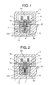
- FIG.1 is a sectional view of the substantial part of the first embodiment of the electromagnetic open/close valve with a poppet valve of an electromagnetic controlled unit injector for a diesel engine according to the present invention.
- reference numeral 6 is a solenoid device
- 6a is a electromagnetic coil of the solenoid device
- 1 is a poppet valve
- 5a is a poppet valve spring
- 2 is a valve seat member in which the poppet valve 1 is fitted reciprocatably
- 4 indicates the seat portion where the poppet valve 1 sits on.
- the poppet valve 1 is reciprocated by the attraction of solenoid device 6 and the spring force of the poppet valve spring 5a.
- Reference numeral 2a is a fuel pool communicating to a fuel passage 2b
- 3 is a spill passage in the valve seat member 2.
- Reference numeral 5 is an armature fixed to the upper end of the poppet valve 1, the armature can be attracted by the electromagnetic coil 6a.
- Reference numeral 1a is an inside space formed inside the poppet valve 1 to extend along the center axis 1b of the poppet valve.
- the inside space 1a is substantially an enclosed space closed with a fixing bolt 11 for fixing the armature 5 at the upper side thereof and closed with a plug 12 at the lower side thereof.
- Reference numeral 10 is a plurality of spherical bodies received in the inside space 1a.
- the spherical bodies 10 may be steel balls, rubber balls, or plastic balls.
- the spherical bodies 10 are received in the inside space 1a so that they can move axially therein contacting with each other when the poppet valve 1 reciprocates.
- the spherical bodies 10 such as steel balls are received axially movably in the enclosed space 1a provided inside the poppet valve 1 reciprocated by the solenoid device 6 and poppet valve spring 5a
- the solenoid device 6 when the solenoid device 6 is excited and the poppet valve 1 is moved upward at the injection beginning and the poppet valve 1 sits on the seat portion 4 of the valve seat member 2 and stops upward moving, the spherical bodies 10 received axially movably in the inside space 1a of the poppet valve 1 continue upward moving and some of the spherical bodies 10 collides against the upper end of the inside space 1a, i.e. the lower end of the fixing bolt 11, and exerts upward force to the poppet valve 1 at the beginning of rebound of the poppet valve 1 to push it up to counteract the downward rebounding force thereof.
- the time from the departure of the spherical bodies from the lower end of the inside space 1a when the poppet valve 1 sits on the seat portion 4 of the valve seat member 2 until the collision against the upper end of the inside space 1a differs according to velocity of the spherical bodies and distance of move thereof in the inside space 1a, and the velocity is influenced by the resistance against the move of the spherical bodies in the inside space 1a and the distance of move also changes according to operating conditions. Therefore, it is possible to make the number of the spherical bodies that collide against the poppet valve stochastically constant by receiving a plurality of the spherical bodies in the inside space in spite of change in the resistance and operating conditions.
- Stable bounce restraining effect can be attained through achieving nearly constant probability of collision of the spherical bodies against the poppet valve by increasing the number of the spherical bodies. Further, the probability of the collision can be adjusted by receiving the spherical bodies in the inside space 1a together with fuel or lube oil or by a method described in the second embodiment explained later.
- FIG.3 is a drawing for explaining the relation between the stroke of the poppet valve and the movable range of spherical bodies received in the inside space 1a of the poppet valve in the first embodiment shown in FIG. 1 .
- the distance (Ls) of movement of the mass objects 10 in the inside space 1a in the axial direction of the poppet valve is defined to be equal to or smaller than the stroke (Lp) of reciprocation of the poppet valve, i.e. (Ls ⁇ Lp) as shown in FIG.3 .
- the vibration system consisting of attraction force of the solenoid device 6, the mass of the poppet valve 1 including the armature 5, spring force of the poppet valve spring 5a, and spring constant at the seat portion 4 of the valve seat member 2 begins to vibrate and bouncing of the poppet valve 1 repeats, that is, bounce vibration occurs.
- the spherical bodies 10 is allowed to reciprocate more than once in the inside space 1a by composing such that Ls ⁇ Lp, and can exert inertia force to the poppet valve 1 in the direction opposite to the vibration direction of the poppet valve bounce vibration and the bounce vibration can be restrained.
- FIG.3 component members same as those of FIG. 1 are designated with the same reference numerals.
- the spherical bodies 10 received in the inside space 1a of the poppet valve 1 are solid bodies, they can be inserted easily into the inside space 1a, fear of spilling of them from the inside space 1a when inserting them or during operation of the engine is eliminated, handling is easy, and safety is increased.
- FIG.2 is a drawing of a second embodiment corresponding to FIG.1 . This embodiment is not claimed in this application.
- a plurality of needle bodies 15 are received in the inside space 1a of the poppet valve 1 instead of the spherical bodies 10.
- Each of the needle bodies 15 is of needle-like or bar-like shape made of steel, rubber, or plastic material, and a plurality of them are received in the inside space 1a movably in the axial direction 1b of the poppet valve 1 and capably of contacting with each other on their outer surfaces.
- the number of collision of the needle-like bodies against the poppet valve in the axial direction can be increased compared to the case of spherical bodies in which the spherical bodies collide with each other in the axial direction. Further, contacting portion increases and friction resistance when the needle-like bodies move in the inside space 1a of the poppet valve 1 can be increased.
- the time the needle bodies 15 collide against the upper end or lower end of the inside space 1a can be optimized for restraining rebounding of the poppet valve when it sits on the seat portion 4 of the valve seat member 2 or sits on the seat face of the injector body 51 as mentioned in the explanation of the first invention.
- Other construction is the same as that of the first embodiment of FIG. 1 , and components members same as those of FIG. 1 are designated with the same reference numerals.
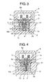
- FIG.4 is a drawing of the third embodiment corresponding to FIG.1
- FIG.5 is a drawing for explaining the relation between the stroke of the poppet valve and the movable range of spherical bodies received inside the poppet valve in the third embodiment shown in FIG.4
- FIG.6 is an enlarged detail of the part indicated with an arrow Z in the third embodiment shown in FIG.4 and FIG.5 .
- a plurality of spherical bodies 10 are received in an inside space 1a of a poppet valve 1 so that they can move axially therein contacting with each other when the poppet valve 1 reciprocates the same as is in the first embodiment, and a small hole 13 is provided in a plug 12 plugging the inside space 1a through which the inside space 1a is communicated to an outside fuel passage, i.e. a passage near the poppet valve 1.
- fuel can flow into or out from the inside space 1a of the poppet valve 1 through the small hole 13 allowing the inside space 1a to communicate to the outside fuel passage, thus a dash pot function is realized, so the bouncing of the poppet valve 1 can be restrained by the damping effect of the dash pot function.
- the spherical bodies 10 perform to restrain bouncing of the poppet valve by inertia force similarly as is done in the first embodiment.
- the distance (Ls) of movement of the mass objects in the inside space, where fuel oil can flow into or out from through the small hole, in the axial direction of the poppet valve is defined to be equal to or smaller than the stroke(Lp) of reciprocation of the poppet valve, i.e. (Ls ⁇ Lp) as shown in FIG.5 .
- FIG.5 components members same as those of FIG.4 are designated with the same reference numerals.
- effect of restraining bouncing is further increased by being doubly effected by the damping effect of the dash pot function and the bounce restraining effect of the inertia force of the mass objects.
- the spherical bodies 10 received in the inside space 1a can be replaced by the needle bodies 15 of the second embodiment.
- bouncing can be restrained only by the dash pot function without receiving in the inside space 1a the spherical bodies 10 or needle bodies 15.
- an electronic controlled fuel injection apparatus composed to control the fuel injection at the beginning and end of the injection by the reciprocation of the poppet valve improved in safety and eased in handling can be provided, in which effect of preventing or restraining bouncing of the poppet valve is increased by utilizing inertia and friction force arising from the reciprocating moving of the poppet valve.
Landscapes
- Engineering & Computer Science (AREA)
- Chemical & Material Sciences (AREA)
- Combustion & Propulsion (AREA)
- Mechanical Engineering (AREA)
- General Engineering & Computer Science (AREA)
- Fuel-Injection Apparatus (AREA)
Claims (4)
- Elektromagnetisch gesteuerte Kraftstoffeinspritzvorrichtung mit einem Tellerventil (1), die derart zusammengesetzt ist, daß der Beginn und das Ende der Kraftstoffeinspritzung durch das Öffnen und Schließe eines Kanals gesteuert werden, der die Verbindung mit einem Kraftstoffkanal (9) herstellt, der mit einem Kolbenraum (8), in dem der Kraftstoff von einem Kolben (7) auf einen hohen Druck komprimiert wird, und einem Überlaufkanal (3) verbunden ist, der mit Hilfe eines Tellerventils, das von einer Elektromagnetvorrichtung (6) und einer Tellerventilfeder (5a) in Axialrichtung hin- und herbewegt wird, mit einer Kraftstoffrücklaufleitung verbunden ist, dadurch gekennzeichnet, daß das Tellerventil einen abgedichteten Innenraum (1a) und mehrere Massenobjekte (10) aufweist, die kugelförmige Körper aus einem metallhaltigen Material sind, in dem Innenraum in einer einzelnen Reihe aufgenommen sind, so daß sich die Massenobjekte in dem Innenraum in Axialrichtung bewegen können und dabei die Möglichkeit zum Inkontaktkommen mit den vorhergehenden und den nachfolgenden Massenobjekten in der Reihe haben, wobei die Bewegungen auf Grund der Trägheitskraft erfolgen, die von der Hin- und Herbewegung des Tellerventils erzeugt wird.
- Elektromagnetisch gesteuerte Kraftstoffeinspritzvorrichtung mit einem Tellerventil (1) nach Anspruch 1, dadurch gekennzeichnet, daß der Abstand (Ls) der Bewegung der Massenobjekte (10) in dem Innenraum (1a) in der Axialrichtung des Tellerventils als gleich dem Hub (Lp) der Hin- und Herbewegung des Tellerventils oder kleiner als dieser, d.h. (Ls ≤ Lp), definiert ist.
- Elektromagnetisch gesteuerte Kraftstoffeinspritzvorrichtung mit einem Tellerventil (1) nach einem der Ansprüche 1 - 2, dadurch gekennzeichnet, daß die Massenobjekte (10) zusammen mit Flüssigkeit wie Kraftstoff oder Schmieröl in dem Innenraum (1a) des Tellerventils aufgenommen sind.
- Elektromagnetisch gesteuerte Kraftstoffeinspritzvorrichtung mit einem Tellerventil (1) nach einem der Ansprüchen 1 bis 3, wobei der Innenraum an einem Ende oder jedem von beiden Enden eine kleine Öffnung zum Verbinden des Innenraums mit einem äußeren Kraftstoffkanal aufweist, wodurch der Kraftstoff auf Grund der Hin- und Herbewegung des Tellerventils durch die kleine Öffnung hindurch in den Innenraum hinein oder aus diesem heraus strömen kann.
Applications Claiming Priority (2)
| Application Number | Priority Date | Filing Date | Title |
|---|---|---|---|
| JP2005049304 | 2005-02-24 | ||
| JP2005334725A JP4634285B2 (ja) | 2005-02-24 | 2005-11-18 | ポペット弁を備えた電磁制御燃料噴射装置 |
Publications (2)
| Publication Number | Publication Date |
|---|---|
| EP1703120A1 EP1703120A1 (de) | 2006-09-20 |
| EP1703120B1 true EP1703120B1 (de) | 2008-11-12 |
Family
ID=36084414
Family Applications (1)
| Application Number | Title | Priority Date | Filing Date |
|---|---|---|---|
| EP20060110374 Ceased EP1703120B1 (de) | 2005-02-24 | 2006-02-24 | Elektromagnetisch gesteuerte Kraftstoffeinspritzanordnung mit Ventil |
Country Status (5)
| Country | Link |
|---|---|
| US (1) | US7350539B2 (de) |
| EP (1) | EP1703120B1 (de) |
| JP (1) | JP4634285B2 (de) |
| AT (1) | ATE414224T1 (de) |
| DE (1) | DE602006003581D1 (de) |
Families Citing this family (7)
| Publication number | Priority date | Publication date | Assignee | Title |
|---|---|---|---|---|
| JP4227965B2 (ja) * | 2005-02-28 | 2009-02-18 | 三菱重工業株式会社 | 電磁制御燃料噴射装置 |
| JP2008045486A (ja) * | 2006-08-16 | 2008-02-28 | Yanmar Co Ltd | 蓄圧式燃料噴射装置 |
| JP4719140B2 (ja) * | 2006-12-20 | 2011-07-06 | 三菱重工業株式会社 | 電磁弁装置及びこれを備えたエンジンの燃料噴射装置 |
| DE102009006987B3 (de) * | 2009-01-31 | 2010-09-30 | Deutsches Zentrum für Luft- und Raumfahrt e.V. | Magnetventil |
| US7942349B1 (en) | 2009-03-24 | 2011-05-17 | Meyer Andrew E | Fuel injector |
| EP2363592A1 (de) * | 2010-02-25 | 2011-09-07 | Continental Automotive GmbH | Einspritzventil |
| US11118698B2 (en) * | 2018-07-23 | 2021-09-14 | Pratt & Whiiney Canada Corp. | Damping mechanism for valves |
Family Cites Families (15)
| Publication number | Priority date | Publication date | Assignee | Title |
|---|---|---|---|---|
| US455913A (en) * | 1891-07-14 | Means for equalizing the pressure of gas in gas service-pipes | ||
| US4566485A (en) * | 1984-11-19 | 1986-01-28 | Ruhle James L | Free-floating neutrally-buoyant reciprocating pump valve for abrasive fluids |
| JPH05223031A (ja) * | 1992-02-12 | 1993-08-31 | Nippondenso Co Ltd | 燃料噴射弁 |
| DE4332117B4 (de) * | 1993-09-22 | 2005-05-04 | Robert Bosch Gmbh | Elektromagnetventil |
| US5392811A (en) * | 1993-11-02 | 1995-02-28 | Caterpillar Inc. | High pressure fuel system valve |
| US5443209A (en) * | 1994-08-02 | 1995-08-22 | Diesel Technology Company | High pressure diesel fuel injector for internal combustion engines |
| US5954487A (en) | 1995-06-23 | 1999-09-21 | Diesel Technology Company | Fuel pump control valve assembly |
| US5984259A (en) * | 1997-11-26 | 1999-11-16 | Saturn Electronics & Engineering, Inc. | Proportional variable force solenoid control valve with armature damping |
| DE19820341C2 (de) * | 1998-05-07 | 2000-04-06 | Daimler Chrysler Ag | Betätigungsvorrichtung für eine Hochdruck-Einspritzdüse für flüssige Einspritzmedien |
| US6109541A (en) * | 1998-07-23 | 2000-08-29 | Caterpillar Inc. | Apparatus for reducing the bounce of a poppet valve |
| US6021999A (en) * | 1998-08-11 | 2000-02-08 | Caterpillar Inc. | Bounce suppression device for high speed poppet valve |
| US6145805A (en) * | 1999-08-23 | 2000-11-14 | Caterpillar Inc. | Liquid control valve assembly with local damping and hydraulically actuated fuel injector using same |
| JP2002098024A (ja) * | 2000-09-26 | 2002-04-05 | Mitsubishi Heavy Ind Ltd | 電子制御燃料噴射装置 |
| US6874703B2 (en) | 2002-06-11 | 2005-04-05 | General Motors Corporation | Anti-bounce needle valve for a fuel injector |
| US6702207B2 (en) * | 2002-07-16 | 2004-03-09 | Robert Bosch Gmbh | Fuel injector control module with unidirectional dampening |
-
2005
- 2005-11-18 JP JP2005334725A patent/JP4634285B2/ja not_active Expired - Fee Related
-
2006
- 2006-02-23 US US11/359,435 patent/US7350539B2/en not_active Expired - Lifetime
- 2006-02-24 DE DE200660003581 patent/DE602006003581D1/de not_active Expired - Fee Related
- 2006-02-24 AT AT06110374T patent/ATE414224T1/de not_active IP Right Cessation
- 2006-02-24 EP EP20060110374 patent/EP1703120B1/de not_active Ceased
Also Published As
| Publication number | Publication date |
|---|---|
| JP4634285B2 (ja) | 2011-02-16 |
| ATE414224T1 (de) | 2008-11-15 |
| DE602006003581D1 (de) | 2008-12-24 |
| EP1703120A1 (de) | 2006-09-20 |
| US7350539B2 (en) | 2008-04-01 |
| US20060185650A1 (en) | 2006-08-24 |
| JP2006266254A (ja) | 2006-10-05 |
Similar Documents
| Publication | Publication Date | Title |
|---|---|---|
| EP1045135B1 (de) | Brennstoffeinspritzventil | |
| KR100347430B1 (ko) | 충돌완화된아마츄어와니들밸브조립체 | |
| KR100558588B1 (ko) | 자기밸브 | |
| KR100531744B1 (ko) | 연료분사기용 전자석 계량밸브 | |
| US7252245B2 (en) | Fuel injection valve | |
| KR102301677B1 (ko) | 연료 분사기 | |
| EP2336544A1 (de) | Prallschutzmechanismus für Kraftstoffverteiler | |
| US5967413A (en) | Damped solenoid actuated valve and fuel injector using same | |
| EP1801409B1 (de) | Kraftstoffinjektor | |
| EP1703120B1 (de) | Elektromagnetisch gesteuerte Kraftstoffeinspritzanordnung mit Ventil | |
| JP2004519609A (ja) | 内燃機関の噴射弁を制御するための電磁弁 | |
| US5284302A (en) | Fuel injection valve | |
| US6702207B2 (en) | Fuel injector control module with unidirectional dampening | |
| JP2004511718A (ja) | 内燃機関の噴射弁を制御するための磁石弁 | |
| JP2006266254A5 (de) | ||
| KR20200103716A (ko) | 유체 계량 밸브 | |
| US7467781B2 (en) | Poppet valve device and electronic controlled fuel injection apparatus equipped with the device | |
| US20180195477A1 (en) | Valve for metering a fluid | |
| CN112955643B (zh) | 螺线管机构及高压燃料泵 | |
| KR102706035B1 (ko) | 유체 계량용 밸브 | |
| US20190120189A1 (en) | Solenoid valve for controlling fluids | |
| JP2005069233A (ja) | 燃料噴射弁及びこれを搭載した内燃機関 | |
| JP2001214835A (ja) | 燃料噴射弁およびこれを搭載する内燃機関 | |
| JP2001020835A (ja) | 燃料噴射弁及びこれを搭載する内燃機関 |
Legal Events
| Date | Code | Title | Description |
|---|---|---|---|
| PUAI | Public reference made under article 153(3) epc to a published international application that has entered the european phase |
Free format text: ORIGINAL CODE: 0009012 |
|
| AK | Designated contracting states |
Kind code of ref document: A1 Designated state(s): AT BE BG CH CY CZ DE DK EE ES FI FR GB GR HU IE IS IT LI LT LU LV MC NL PL PT RO SE SI SK TR |
|
| AX | Request for extension of the european patent |
Extension state: AL BA HR MK YU |
|
| 17P | Request for examination filed |
Effective date: 20061227 |
|
| 17Q | First examination report despatched |
Effective date: 20070202 |
|
| AKX | Designation fees paid |
Designated state(s): AT DE FR GB |
|
| GRAP | Despatch of communication of intention to grant a patent |
Free format text: ORIGINAL CODE: EPIDOSNIGR1 |
|
| GRAS | Grant fee paid |
Free format text: ORIGINAL CODE: EPIDOSNIGR3 |
|
| GRAA | (expected) grant |
Free format text: ORIGINAL CODE: 0009210 |
|
| AK | Designated contracting states |
Kind code of ref document: B1 Designated state(s): AT DE FR GB |
|
| REG | Reference to a national code |
Ref country code: GB Ref legal event code: FG4D |
|
| REF | Corresponds to: |
Ref document number: 602006003581 Country of ref document: DE Date of ref document: 20081224 Kind code of ref document: P |
|
| PGFP | Annual fee paid to national office [announced via postgrant information from national office to epo] |
Ref country code: AT Payment date: 20090120 Year of fee payment: 4 |
|
| PGFP | Annual fee paid to national office [announced via postgrant information from national office to epo] |
Ref country code: DE Payment date: 20090211 Year of fee payment: 4 |
|
| PLBE | No opposition filed within time limit |
Free format text: ORIGINAL CODE: 0009261 |
|
| STAA | Information on the status of an ep patent application or granted ep patent |
Free format text: STATUS: NO OPPOSITION FILED WITHIN TIME LIMIT |
|
| 26N | No opposition filed |
Effective date: 20090813 |
|
| GBPC | Gb: european patent ceased through non-payment of renewal fee |
Effective date: 20100224 |
|
| PG25 | Lapsed in a contracting state [announced via postgrant information from national office to epo] |
Ref country code: DE Free format text: LAPSE BECAUSE OF NON-PAYMENT OF DUE FEES Effective date: 20100901 |
|
| PG25 | Lapsed in a contracting state [announced via postgrant information from national office to epo] |
Ref country code: GB Free format text: LAPSE BECAUSE OF NON-PAYMENT OF DUE FEES Effective date: 20100224 |
|
| PG25 | Lapsed in a contracting state [announced via postgrant information from national office to epo] |
Ref country code: AT Free format text: LAPSE BECAUSE OF NON-PAYMENT OF DUE FEES Effective date: 20110224 |
|
| REG | Reference to a national code |
Ref country code: FR Ref legal event code: PLFP Year of fee payment: 11 |
|
| REG | Reference to a national code |
Ref country code: FR Ref legal event code: PLFP Year of fee payment: 12 |
|
| REG | Reference to a national code |
Ref country code: FR Ref legal event code: PLFP Year of fee payment: 13 |
|
| PGFP | Annual fee paid to national office [announced via postgrant information from national office to epo] |
Ref country code: FR Payment date: 20210113 Year of fee payment: 16 |
|
| PG25 | Lapsed in a contracting state [announced via postgrant information from national office to epo] |
Ref country code: FR Free format text: LAPSE BECAUSE OF NON-PAYMENT OF DUE FEES Effective date: 20220228 |