EP1702864A1 - Transport- und Lagergestell - Google Patents
Transport- und Lagergestell Download PDFInfo
- Publication number
- EP1702864A1 EP1702864A1 EP06110670A EP06110670A EP1702864A1 EP 1702864 A1 EP1702864 A1 EP 1702864A1 EP 06110670 A EP06110670 A EP 06110670A EP 06110670 A EP06110670 A EP 06110670A EP 1702864 A1 EP1702864 A1 EP 1702864A1
- Authority
- EP
- European Patent Office
- Prior art keywords
- transport
- storage rack
- rotation
- axis
- rack according
- Prior art date
- Legal status (The legal status is an assumption and is not a legal conclusion. Google has not performed a legal analysis and makes no representation as to the accuracy of the status listed.)
- Granted
Links
- 239000000969 carrier Substances 0.000 description 8
- 238000010276 construction Methods 0.000 description 4
- 229910000831 Steel Inorganic materials 0.000 description 2
- 239000000463 material Substances 0.000 description 2
- 229910052751 metal Inorganic materials 0.000 description 2
- 239000010959 steel Substances 0.000 description 2
- 230000015572 biosynthetic process Effects 0.000 description 1
- 238000006073 displacement reaction Methods 0.000 description 1
- 239000002184 metal Substances 0.000 description 1
- 239000000203 mixture Substances 0.000 description 1
- 230000003068 static effect Effects 0.000 description 1
- 230000002459 sustained effect Effects 0.000 description 1
Images
Classifications
-
- B—PERFORMING OPERATIONS; TRANSPORTING
- B65—CONVEYING; PACKING; STORING; HANDLING THIN OR FILAMENTARY MATERIAL
- B65D—CONTAINERS FOR STORAGE OR TRANSPORT OF ARTICLES OR MATERIALS, e.g. BAGS, BARRELS, BOTTLES, BOXES, CANS, CARTONS, CRATES, DRUMS, JARS, TANKS, HOPPERS, FORWARDING CONTAINERS; ACCESSORIES, CLOSURES, OR FITTINGS THEREFOR; PACKAGING ELEMENTS; PACKAGES
- B65D88/00—Large containers
- B65D88/52—Large containers collapsible, i.e. with walls hinged together or detachably connected
- B65D88/522—Large containers collapsible, i.e. with walls hinged together or detachably connected all side walls hingedly connected to each other or to another component of the container
-
- B—PERFORMING OPERATIONS; TRANSPORTING
- B65—CONVEYING; PACKING; STORING; HANDLING THIN OR FILAMENTARY MATERIAL
- B65D—CONTAINERS FOR STORAGE OR TRANSPORT OF ARTICLES OR MATERIALS, e.g. BAGS, BARRELS, BOTTLES, BOXES, CANS, CARTONS, CRATES, DRUMS, JARS, TANKS, HOPPERS, FORWARDING CONTAINERS; ACCESSORIES, CLOSURES, OR FITTINGS THEREFOR; PACKAGING ELEMENTS; PACKAGES
- B65D19/00—Pallets or like platforms, with or without side walls, for supporting loads to be lifted or lowered
- B65D19/02—Rigid pallets with side walls, e.g. box pallets
- B65D19/06—Rigid pallets with side walls, e.g. box pallets with bodies formed by uniting or interconnecting two or more components
- B65D19/18—Rigid pallets with side walls, e.g. box pallets with bodies formed by uniting or interconnecting two or more components made wholly or mainly of plastics material
-
- B—PERFORMING OPERATIONS; TRANSPORTING
- B65—CONVEYING; PACKING; STORING; HANDLING THIN OR FILAMENTARY MATERIAL
- B65D—CONTAINERS FOR STORAGE OR TRANSPORT OF ARTICLES OR MATERIALS, e.g. BAGS, BARRELS, BOTTLES, BOXES, CANS, CARTONS, CRATES, DRUMS, JARS, TANKS, HOPPERS, FORWARDING CONTAINERS; ACCESSORIES, CLOSURES, OR FITTINGS THEREFOR; PACKAGING ELEMENTS; PACKAGES
- B65D19/00—Pallets or like platforms, with or without side walls, for supporting loads to be lifted or lowered
- B65D19/38—Details or accessories
- B65D19/385—Frames, corner posts or pallet converters, e.g. for facilitating stacking of charged pallets
-
- B—PERFORMING OPERATIONS; TRANSPORTING
- B65—CONVEYING; PACKING; STORING; HANDLING THIN OR FILAMENTARY MATERIAL
- B65D—CONTAINERS FOR STORAGE OR TRANSPORT OF ARTICLES OR MATERIALS, e.g. BAGS, BARRELS, BOTTLES, BOXES, CANS, CARTONS, CRATES, DRUMS, JARS, TANKS, HOPPERS, FORWARDING CONTAINERS; ACCESSORIES, CLOSURES, OR FITTINGS THEREFOR; PACKAGING ELEMENTS; PACKAGES
- B65D85/00—Containers, packaging elements or packages, specially adapted for particular articles or materials
- B65D85/20—Containers, packaging elements or packages, specially adapted for particular articles or materials for incompressible or rigid rod-shaped or tubular articles
-
- B—PERFORMING OPERATIONS; TRANSPORTING
- B65—CONVEYING; PACKING; STORING; HANDLING THIN OR FILAMENTARY MATERIAL
- B65D—CONTAINERS FOR STORAGE OR TRANSPORT OF ARTICLES OR MATERIALS, e.g. BAGS, BARRELS, BOTTLES, BOXES, CANS, CARTONS, CRATES, DRUMS, JARS, TANKS, HOPPERS, FORWARDING CONTAINERS; ACCESSORIES, CLOSURES, OR FITTINGS THEREFOR; PACKAGING ELEMENTS; PACKAGES
- B65D88/00—Large containers
- B65D88/02—Large containers rigid
- B65D88/12—Large containers rigid specially adapted for transport
- B65D88/122—Large containers rigid specially adapted for transport with access from above
- B65D88/123—Large containers rigid specially adapted for transport with access from above open top
-
- B—PERFORMING OPERATIONS; TRANSPORTING
- B65—CONVEYING; PACKING; STORING; HANDLING THIN OR FILAMENTARY MATERIAL
- B65D—CONTAINERS FOR STORAGE OR TRANSPORT OF ARTICLES OR MATERIALS, e.g. BAGS, BARRELS, BOTTLES, BOXES, CANS, CARTONS, CRATES, DRUMS, JARS, TANKS, HOPPERS, FORWARDING CONTAINERS; ACCESSORIES, CLOSURES, OR FITTINGS THEREFOR; PACKAGING ELEMENTS; PACKAGES
- B65D88/00—Large containers
- B65D88/52—Large containers collapsible, i.e. with walls hinged together or detachably connected
- B65D88/522—Large containers collapsible, i.e. with walls hinged together or detachably connected all side walls hingedly connected to each other or to another component of the container
- B65D88/524—Large containers collapsible, i.e. with walls hinged together or detachably connected all side walls hingedly connected to each other or to another component of the container and one or more side walls being foldable along an additional median line
-
- B—PERFORMING OPERATIONS; TRANSPORTING
- B65—CONVEYING; PACKING; STORING; HANDLING THIN OR FILAMENTARY MATERIAL
- B65D—CONTAINERS FOR STORAGE OR TRANSPORT OF ARTICLES OR MATERIALS, e.g. BAGS, BARRELS, BOTTLES, BOXES, CANS, CARTONS, CRATES, DRUMS, JARS, TANKS, HOPPERS, FORWARDING CONTAINERS; ACCESSORIES, CLOSURES, OR FITTINGS THEREFOR; PACKAGING ELEMENTS; PACKAGES
- B65D2519/00—Pallets or like platforms, with or without side walls, for supporting loads to be lifted or lowered
- B65D2519/00004—Details relating to pallets
- B65D2519/00009—Materials
- B65D2519/00014—Materials for the load supporting surface
- B65D2519/00034—Plastic
-
- B—PERFORMING OPERATIONS; TRANSPORTING
- B65—CONVEYING; PACKING; STORING; HANDLING THIN OR FILAMENTARY MATERIAL
- B65D—CONTAINERS FOR STORAGE OR TRANSPORT OF ARTICLES OR MATERIALS, e.g. BAGS, BARRELS, BOTTLES, BOXES, CANS, CARTONS, CRATES, DRUMS, JARS, TANKS, HOPPERS, FORWARDING CONTAINERS; ACCESSORIES, CLOSURES, OR FITTINGS THEREFOR; PACKAGING ELEMENTS; PACKAGES
- B65D2519/00—Pallets or like platforms, with or without side walls, for supporting loads to be lifted or lowered
- B65D2519/00004—Details relating to pallets
- B65D2519/00009—Materials
- B65D2519/00049—Materials for the base surface
- B65D2519/00069—Plastic
-
- B—PERFORMING OPERATIONS; TRANSPORTING
- B65—CONVEYING; PACKING; STORING; HANDLING THIN OR FILAMENTARY MATERIAL
- B65D—CONTAINERS FOR STORAGE OR TRANSPORT OF ARTICLES OR MATERIALS, e.g. BAGS, BARRELS, BOTTLES, BOXES, CANS, CARTONS, CRATES, DRUMS, JARS, TANKS, HOPPERS, FORWARDING CONTAINERS; ACCESSORIES, CLOSURES, OR FITTINGS THEREFOR; PACKAGING ELEMENTS; PACKAGES
- B65D2519/00—Pallets or like platforms, with or without side walls, for supporting loads to be lifted or lowered
- B65D2519/00004—Details relating to pallets
- B65D2519/00009—Materials
- B65D2519/00154—Materials for the side walls
- B65D2519/00169—Wood
-
- B—PERFORMING OPERATIONS; TRANSPORTING
- B65—CONVEYING; PACKING; STORING; HANDLING THIN OR FILAMENTARY MATERIAL
- B65D—CONTAINERS FOR STORAGE OR TRANSPORT OF ARTICLES OR MATERIALS, e.g. BAGS, BARRELS, BOTTLES, BOXES, CANS, CARTONS, CRATES, DRUMS, JARS, TANKS, HOPPERS, FORWARDING CONTAINERS; ACCESSORIES, CLOSURES, OR FITTINGS THEREFOR; PACKAGING ELEMENTS; PACKAGES
- B65D2519/00—Pallets or like platforms, with or without side walls, for supporting loads to be lifted or lowered
- B65D2519/00004—Details relating to pallets
- B65D2519/00009—Materials
- B65D2519/00154—Materials for the side walls
- B65D2519/00174—Plastic
-
- B—PERFORMING OPERATIONS; TRANSPORTING
- B65—CONVEYING; PACKING; STORING; HANDLING THIN OR FILAMENTARY MATERIAL
- B65D—CONTAINERS FOR STORAGE OR TRANSPORT OF ARTICLES OR MATERIALS, e.g. BAGS, BARRELS, BOTTLES, BOXES, CANS, CARTONS, CRATES, DRUMS, JARS, TANKS, HOPPERS, FORWARDING CONTAINERS; ACCESSORIES, CLOSURES, OR FITTINGS THEREFOR; PACKAGING ELEMENTS; PACKAGES
- B65D2519/00—Pallets or like platforms, with or without side walls, for supporting loads to be lifted or lowered
- B65D2519/00004—Details relating to pallets
- B65D2519/00009—Materials
- B65D2519/00223—Materials for the corner elements or corner frames
- B65D2519/00243—Plastic
-
- B—PERFORMING OPERATIONS; TRANSPORTING
- B65—CONVEYING; PACKING; STORING; HANDLING THIN OR FILAMENTARY MATERIAL
- B65D—CONTAINERS FOR STORAGE OR TRANSPORT OF ARTICLES OR MATERIALS, e.g. BAGS, BARRELS, BOTTLES, BOXES, CANS, CARTONS, CRATES, DRUMS, JARS, TANKS, HOPPERS, FORWARDING CONTAINERS; ACCESSORIES, CLOSURES, OR FITTINGS THEREFOR; PACKAGING ELEMENTS; PACKAGES
- B65D2519/00—Pallets or like platforms, with or without side walls, for supporting loads to be lifted or lowered
- B65D2519/00004—Details relating to pallets
- B65D2519/00258—Overall construction
- B65D2519/00263—Overall construction of the pallet
- B65D2519/00273—Overall construction of the pallet made of more than one piece
-
- B—PERFORMING OPERATIONS; TRANSPORTING
- B65—CONVEYING; PACKING; STORING; HANDLING THIN OR FILAMENTARY MATERIAL
- B65D—CONTAINERS FOR STORAGE OR TRANSPORT OF ARTICLES OR MATERIALS, e.g. BAGS, BARRELS, BOTTLES, BOXES, CANS, CARTONS, CRATES, DRUMS, JARS, TANKS, HOPPERS, FORWARDING CONTAINERS; ACCESSORIES, CLOSURES, OR FITTINGS THEREFOR; PACKAGING ELEMENTS; PACKAGES
- B65D2519/00—Pallets or like platforms, with or without side walls, for supporting loads to be lifted or lowered
- B65D2519/00004—Details relating to pallets
- B65D2519/00258—Overall construction
- B65D2519/00283—Overall construction of the load supporting surface
- B65D2519/00293—Overall construction of the load supporting surface made of more than one piece
-
- B—PERFORMING OPERATIONS; TRANSPORTING
- B65—CONVEYING; PACKING; STORING; HANDLING THIN OR FILAMENTARY MATERIAL
- B65D—CONTAINERS FOR STORAGE OR TRANSPORT OF ARTICLES OR MATERIALS, e.g. BAGS, BARRELS, BOTTLES, BOXES, CANS, CARTONS, CRATES, DRUMS, JARS, TANKS, HOPPERS, FORWARDING CONTAINERS; ACCESSORIES, CLOSURES, OR FITTINGS THEREFOR; PACKAGING ELEMENTS; PACKAGES
- B65D2519/00—Pallets or like platforms, with or without side walls, for supporting loads to be lifted or lowered
- B65D2519/00004—Details relating to pallets
- B65D2519/00258—Overall construction
- B65D2519/00313—Overall construction of the base surface
- B65D2519/00323—Overall construction of the base surface made of more than one piece
-
- B—PERFORMING OPERATIONS; TRANSPORTING
- B65—CONVEYING; PACKING; STORING; HANDLING THIN OR FILAMENTARY MATERIAL
- B65D—CONTAINERS FOR STORAGE OR TRANSPORT OF ARTICLES OR MATERIALS, e.g. BAGS, BARRELS, BOTTLES, BOXES, CANS, CARTONS, CRATES, DRUMS, JARS, TANKS, HOPPERS, FORWARDING CONTAINERS; ACCESSORIES, CLOSURES, OR FITTINGS THEREFOR; PACKAGING ELEMENTS; PACKAGES
- B65D2519/00—Pallets or like platforms, with or without side walls, for supporting loads to be lifted or lowered
- B65D2519/00004—Details relating to pallets
- B65D2519/00258—Overall construction
- B65D2519/00313—Overall construction of the base surface
- B65D2519/00328—Overall construction of the base surface shape of the contact surface of the base
- B65D2519/00333—Overall construction of the base surface shape of the contact surface of the base contact surface having a stringer-like shape
-
- B—PERFORMING OPERATIONS; TRANSPORTING
- B65—CONVEYING; PACKING; STORING; HANDLING THIN OR FILAMENTARY MATERIAL
- B65D—CONTAINERS FOR STORAGE OR TRANSPORT OF ARTICLES OR MATERIALS, e.g. BAGS, BARRELS, BOTTLES, BOXES, CANS, CARTONS, CRATES, DRUMS, JARS, TANKS, HOPPERS, FORWARDING CONTAINERS; ACCESSORIES, CLOSURES, OR FITTINGS THEREFOR; PACKAGING ELEMENTS; PACKAGES
- B65D2519/00—Pallets or like platforms, with or without side walls, for supporting loads to be lifted or lowered
- B65D2519/00004—Details relating to pallets
- B65D2519/00258—Overall construction
- B65D2519/00492—Overall construction of the side walls
- B65D2519/00502—Overall construction of the side walls whereby at least one side wall is made of two or more pieces
-
- B—PERFORMING OPERATIONS; TRANSPORTING
- B65—CONVEYING; PACKING; STORING; HANDLING THIN OR FILAMENTARY MATERIAL
- B65D—CONTAINERS FOR STORAGE OR TRANSPORT OF ARTICLES OR MATERIALS, e.g. BAGS, BARRELS, BOTTLES, BOXES, CANS, CARTONS, CRATES, DRUMS, JARS, TANKS, HOPPERS, FORWARDING CONTAINERS; ACCESSORIES, CLOSURES, OR FITTINGS THEREFOR; PACKAGING ELEMENTS; PACKAGES
- B65D2519/00—Pallets or like platforms, with or without side walls, for supporting loads to be lifted or lowered
- B65D2519/00004—Details relating to pallets
- B65D2519/00736—Details
- B65D2519/00741—Dimensional aspects of the pallet
- B65D2519/00746—Dimensional aspects of the pallet divisible into sub-pallets of smaller dimensions
-
- B—PERFORMING OPERATIONS; TRANSPORTING
- B65—CONVEYING; PACKING; STORING; HANDLING THIN OR FILAMENTARY MATERIAL
- B65D—CONTAINERS FOR STORAGE OR TRANSPORT OF ARTICLES OR MATERIALS, e.g. BAGS, BARRELS, BOTTLES, BOXES, CANS, CARTONS, CRATES, DRUMS, JARS, TANKS, HOPPERS, FORWARDING CONTAINERS; ACCESSORIES, CLOSURES, OR FITTINGS THEREFOR; PACKAGING ELEMENTS; PACKAGES
- B65D2519/00—Pallets or like platforms, with or without side walls, for supporting loads to be lifted or lowered
- B65D2519/00004—Details relating to pallets
- B65D2519/00736—Details
- B65D2519/00741—Dimensional aspects of the pallet
- B65D2519/00746—Dimensional aspects of the pallet divisible into sub-pallets of smaller dimensions
- B65D2519/00756—Dimensional aspects of the pallet divisible into sub-pallets of smaller dimensions joined together by removable elements, e.g. bands encircling the feed
-
- B—PERFORMING OPERATIONS; TRANSPORTING
- B65—CONVEYING; PACKING; STORING; HANDLING THIN OR FILAMENTARY MATERIAL
- B65D—CONTAINERS FOR STORAGE OR TRANSPORT OF ARTICLES OR MATERIALS, e.g. BAGS, BARRELS, BOTTLES, BOXES, CANS, CARTONS, CRATES, DRUMS, JARS, TANKS, HOPPERS, FORWARDING CONTAINERS; ACCESSORIES, CLOSURES, OR FITTINGS THEREFOR; PACKAGING ELEMENTS; PACKAGES
- B65D2519/00—Pallets or like platforms, with or without side walls, for supporting loads to be lifted or lowered
- B65D2519/00004—Details relating to pallets
- B65D2519/00736—Details
- B65D2519/00741—Dimensional aspects of the pallet
- B65D2519/00761—Dimensional aspects of the pallet the surface being variable, e.g. extendable pallets
- B65D2519/00766—Dimensional aspects of the pallet the surface being variable, e.g. extendable pallets with one set of interchangeable elements to adapt the surface to different dimensions
Definitions
- the present invention relates to a transport and storage rack, in particular a Langgutpalette, with at least two U-shaped carriers, which are interconnected by profiles and have a bottom-side portion and two upwardly projecting legs.
- a transport and storage rack is known in which a base frame of longitudinal struts and cross struts is formed on the bottom side, wherein on the longitudinal struts upwardly projecting removable plug-in supports are provided.
- the transport and storage rack can be stacked in the unloaded state to save space on each other.
- no crane hooks can engage the plug-in supports and, after the crane cables have been secured to the longitudinal struts, the cables can damage the loading of the transport and storage rack.
- the transport and storage rack is comparatively heavy and therefore expensive to handle.
- At least one axis of rotation is formed on the bottom-side portion of the carrier and the legs can be pivoted so in an expanding position.
- This allows the transport and storage rack are stacked in an open position into each other, so that only a minimum of space required for the transport of empty transport and storage racks.
- the transport and storage rack still retains a high degree of stability for the loaded condition, since the rotation axis is arranged only in the bottom-side section and thus does not weaken the critical point adjacent to the legs.
- a rotation axis is formed centrally on the bottom-side portion.
- the transport and storage rack can be swung open along a median plane and stacked centered one inside the other.
- the load on the bottom-side portion causes a force to be in the closed position. so that the transport and storage rack in the loaded state can not accidentally open.
- the bars abut each other with one end face and offer a high degree of stability, wherein the axis of rotation is loaded only with a certain amount of tension.
- a stop is formed adjacent to the axis of rotation, which limits the maximum opening position of the carrier.
- the stacking position is predetermined and can be dimensioned so that the width of a pallet stack is adapted to the width of a bed of the truck.
- the carriers are preferably stackable in the open position in a W-shape, wherein they can be latched in the open position, which simplifies handling.
- a hinge joint can be fixed to a split beam at the bottom-side portion.
- the hinge joint may be connected to the carrier via plates.
- only a bolt can be provided as the axis of rotation, which is encompassed by webs on the beam of the carrier.
- a plurality of axes of rotation are arranged on the bottom-side portion, so that the bottom-side portion can be folded and the legs are collapsible.
- the carriers are preferably made of plastic.
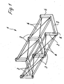
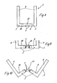
- a transport and storage rack 1 is used to transport elongated up to about 6m long objects, such as profiles, pipes, etc. and is also referred to as Langgutpalette.
- the transport and storage rack 1 consists of several carriers 2 made of plastic, which are U-shaped and have a bottom-side portion 5 and two upwardly projecting leg 6.
- the carrier 2 are connected to each other via profiles 3, which hold the individual carrier 2 at a predetermined distance.
- Between the supports 2 diagonally tensioned clamping elements 4 are mounted, which are arranged like a truss between the profiles 3.
- the transport and storage rack 1 may consist of seven to nine carriers 2, which are interconnected via profiles 3 and clamping elements 4, with only three carriers 2 being shown for better clarity.
- the profiles 3 and clamping elements 4 high forces can be absorbed by the transport and storage rack, for example, when a forklift attacks in the middle or a crane pulls the transport and storage rack 1 on protruding legs 6 and moves without a major deflection takes place.
- the transport and storage rack 1 may be relatively easily formed.
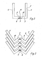
- the bottom-side portion 5 is formed by divided beams 9 and 10, which are each formed integrally with the legs 6.
- a rotation axis 7 is formed on the bottom side, which is formed by a hinge joint which is fixed with plates 8 on the beam 9 and 10 respectively.
- the beams 9 and 10 In the closed state, the beams 9 and 10 abut each other with an end face 11, and by loading, the carrier 2 is also held in the closed position, regardless of whether a forklift engages under a carrier 2 or a crane at the top of the legs 6 attacks.
- the carriers 2 are shown in the opened and nested position.
- the bottom portion 5 has been pivoted with the split beam 9 and 10 about the axis 7, so that the legs 6 are slightly spread apart.
- the maximum opening position of the transport and storage rack 1 may be limited by a stop which is arranged adjacent to the axis of rotation 7.
- the transport and storage racks 1 can also be locked in the slightly open position in order to be able to move them back into the closed position only after applying a certain force.
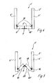
- FIG. 4 shows a modified embodiment of a transport and storage rack 1 'is shown.
- the transport and storage rack 1 ' comprises U-shaped support 2', the upwardly projecting leg 6 'and the bottom side have a portion 5'.
- the bottom-side portion 5 ' is formed of two beams 9' and 10 ', which are connected centrally via a hinge joint with a rotation axis 7.
- the beams 9' and 10 ' are over another hinge joint connected to a rotation axis 16.
- the U-shaped contour shown in Figures 1 and 2 results again.
- the transport and storage rack 1 ' is shown in a possible transport position without loading.
- the bottom-side bars 9 'and 10' have been pivoted about the axes 7 and 16, so that the bar 9 'and 10' is folded and the legs 6 'are pushed together.
- the folding mechanism can also be made until a side surface 17 of the beam 9 'abuts against the leg 6' and the lower sides 19 and 20 of the beams 9 'and 10' abut each other and further the surface of the beam 10 'adjacent to the leg 6' , Then the transport and storage rack 1 'is completely folded and requires only a small space.
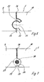
- FIG 6 a transport and storage rack 1 according to Figures 1 and 2 is shown, in which the axis of rotation 7 is designed modified.
- a rotation axis 21 on the bottom-side portion 5 is integrally formed with the one beam 10 of the carrier 2, while on the beam 9, a web portion 22 is provided which engages around the rotation axis 21.
- these are pivotable about the rotation axis 21, wherein below the rotation axis 21, a gap 23 is provided so that a projection on the beam 9 can pivot into the gap up to a stop 25.
- the maximum open position of the carrier 2 is predetermined. In the closed position, the beams 9 and 10 rest against one another with an end face 24 above the axis of rotation 21.
- FIG. 7 shows a further embodiment of a transport and storage rack in the region of the bottom-side section 5, in which the bars 9 and 10 are pivotable about an axis 26.
- the axis 26 is formed by a metallic bolt, which is encompassed by webs 27 and 28.
- the axis 26 can not be moved in the radial direction, since the webs 27 and 28 engage around this substantially form-fitting manner.
- a gap 23 is provided, so that the bars 9 and 10 can be pivoted to a stop 25 in the open position.
- the beams 9 and 10 rest against a front face 24 in a closed position.
- FIGS. 8 to 10 An embodiment of the invention is shown in FIGS. 8 to 10, in which the axes of rotation 7, which make it possible to unfold into the transport position according to FIG. 10, are arranged in the region of a central part 12.
- the central part 12 is formed in three parts in total, and accordingly two axes of rotation 7 are provided.
- the extent so far symmetrically formed central portion 12 with the axes of rotation 7 may be arranged displaceably within the beams 9 and 10. It is also possible to postpone the middle part 12 as a sleeve on the adjacent ends of the beams.
- the carrier 2 can be swung back into a position shown in FIG 9 and then completely pushed together, so that again the starting position of Figure 8 is taken.
- This construction is advantageous insofar as only a transverse displacement of the two halves of the carrier 2 is necessary in order to move from the stacking position according to FIG. 10 into the use position according to FIG. 8 or vice versa.
- constructions according to the invention are of course also applicable to pallets of metal, in particular of steel and other materials, in which the handling and stackability is in the foreground.
- the rotation axis 7, 21 and 26 are each closer to the bottom than at the top of the bottom-side portion 5 of the carrier. 2 arranged.
- the axis of rotation it is also possible to arrange the axis of rotation further up, if this simplifies handling.
- the central part 12 may also be formed in two parts and then be equipped according to only one axis of rotation 7. In the latter case, then an asymmetrical construction of the central part 12, while the central part 12 in the case of its three-part design with two axes of rotation 7, as shown in Figures 8 to 10, has a symmetrical construction.
- the middle part 12 can be inserted into the bottom-side section 5, so that the axes of rotation 7 are concealed in the state of charge and a kink-resistant connection is provided. For transport then the middle-side section 5 can be moved so that the central part 12 with the axes of rotation 7 allows spreading of the transport and storage rack 1.
- the carrier 2 and 3 profiles are made of plastic.
- plastic and metal elements which still have a lower dead weight than the long pallets made of steel.
- 6 hooks can be provided with metallic fasteners on the legs, so that the transport and storage rack 1 can also be transported hanging.
Landscapes
- Engineering & Computer Science (AREA)
- Mechanical Engineering (AREA)
- Pallets (AREA)
- Vending Machines For Individual Products (AREA)
- Warehouses Or Storage Devices (AREA)
- Bending Of Plates, Rods, And Pipes (AREA)
- Stackable Containers (AREA)
- Casings For Electric Apparatus (AREA)
- Floor Finish (AREA)
Abstract
Description
- Die vorliegende Erfindung betrifft ein Transport- und Lagergestell, insbesondere eine Langgutpalette, mit mindestens zwei U-förmigen Trägem, die über Profile miteinander verbunden sind und einen bodenseitigen Abschnitt sowie zwei nach oben hervorstehende Schenkel aufweisen.
- Aus der
DE 93 13 003 ist ein Transport- und Lagergestell bekannt, bei dem bodenseitig ein Grundrahmen aus Längsstreben und Querstreben gebildet ist, wobei an den Längsstreben nach oben ragende entfernbare Einsteckstützen vorgesehen sind. Durch Herausnehmen der Einsteckstützen kann das Transport- und Lagergestell im nicht beladenen Zustand raumsparend übereinander gestapelt werden. Nachteilig ist jedoch, daß alle Einsteckstützen einzeln demontiert werden müssen und somit die Montage und Demontage vergleichsweise aufwendig ist. Zudem besteht der Nachteil, daß an den Einsteckstützen keine Kranhaken eingreifen können und nach dem Festlegen der Kranseile an den Längsstreben die Seile die Beladung des Transport-und Lagergestells beschädigen kann. Ferner ist das Transport- und Lagergestell vergleichsweise schwer und damit aufwendig in der Handhabung. - Aus der
DE 42 33 673 ist ein Transportgestell für Langgut bekannt, bei dem U-förmige Träger vorgesehen sind, deren seitliche Schenkel nach innen verschwenkt werden können. Dadurch können die leeren Transportgestelle raumsparend gestapelt werden. Der Drehpunkt an den Schenkeln ist jedoch für statische Belastungen ungünstig und die Stabilität des Transportgestells begrenzt. Zudem besteht der Nachteil, daß ein Kran an den Schenkeln nicht angreifen kann, da diese sonst aus ihrer fixierten Position herausgezogen werden. - Es ist daher Aufgabe der vorliegenden Erfindung ein Transport- und Lagergestell zu schaffen, das einen stabilen Aufbau besitzt und im Leerzustand nur ein geringes Lagervolumen benötigt. Ferner sollen auch hohe mechanische Belastungen ausgehalten werden können.
- Diese Aufgabe wird mit einem Transport- und Lagergestell mit den Merkmalen des Anspruches 1 gelöst.
- Erfindungsgemäß ist an dem bodenseitigen Abschnitt der Träger mindestens eine Drehachse ausgebildet und die Schenkel können so in eine aufspreizende Position verschwenkt werden. Dadurch kann das Transport- und Lagergestell in einer geöffneten Position ineinander gestapelt werden, so daß nur ein Minimum an Platzbedarf für den Transport leerer Transport- und Lagergestelle benötigt wird. Das Transport-und Lagergestell behält dennoch für den beladenen Zustand ein hohes Maß an Stabilität, da die Drehachse nur in dem bodenseitigen Abschnitt angeordnet ist und somit nicht den kritischen Punkt benachbart zu den Schenkeln schwächt.
- Gemäß einer bevorzugten Ausgestaltung der Erfindung ist eine Drehachse mittig an dem bodenseitigen Abschnitt ausgebildet. Dadurch kann das Transport- und Lagergestell entlang einer Mittelebene aufgeschwenkt werden und zentriert ineinander gestapelt werden.
- Wenn der bodenseitige Abschnitt durch einen geteilten Balken gebildet ist und die Drehachse näher am Boden als an der Oberseite des Balkens angeordnet ist, bewirkt die Ladung auf dem bodenseitigen Abschnitt eine Kraft in die geschlossene Position, so daß sich das Transport- und Lagergestell im beladenen Zustand nicht versehentlich öffnen kann. Zudem liegen die Balken mit einer Stirnseite aneinander an und bieten ein hohes Maß an Stabilität, wobei die Drehachse nur mit einem gewissen Zug belastet ist.
- Gemäß einer weiteren Ausgestaltung der Erfindung ist benachbart zu der Drehachse ein Anschlag ausgebildet, der die maximale Öffnungsstellung der Träger begrenzt. Dadurch wird die Stapelposition vorgegeben und kann so bemessen werden, daß die Breite eines Palettenstapels an die Breite einer Ladefläche des Lkw angepaßt ist. Die Träger sind in der geöffneten Position vorzugsweise W-förmig stapelbar, wobei sie in der geöffneten Position verrastbar sein können, was die Handhabung vereinfacht.
- Für eine besonders stabile Ausbildung der Drehachse kann ein Scharniergelenk an einem geteilten Balken an dem bodenseitigen Abschnitt festgelegt sein. Das Scharniergelenk kann über Platten mit dem Träger verbunden sein. Alternativ kann als Drehachse auch nur ein Bolzen vorgesehen sein, der von Stegen an dem Balken des Trägers umgriffen ist.
- Gemäß einer weiteren Ausgestaltung der Erfindung sind mehrere Drehachsen an dem bodenseitigen Abschnitt angeordnet, so daß der bodenseitige Abschnitt zusammengefaltet werden kann und die Schenkel zusammenschiebbar sind.
- Für ein möglichst geringes Gewicht des Transport- und Lagergestells bestehen die Träger vorzugsweise aus Kunststoff.
- Die Erfindung wird nachfolgend anhand mehrerer Ausführungsbeispiele mit Bezug auf die beigefügten Zeichnungen näher beschrieben. Es zeigen:
- Figur 1
- eine perspektivische Ansicht eines Ausführungsbeispiels eines Transport- und Lagergestells;
- Figur 2
- eine Seitenansicht auf das Transport- und Lagergestell der Figur 1 im geschlossenen Zustand;
- Figur 3
- eine Seitenansicht des Transport- und Lagergestells in der gestapelten Position;
- Figur 4
- eine Seitenansicht eines modifizierten Ausführungsbeispiels;
- Figur 5
- eine Seitenansicht des in Figur 4 gezeigten Ausführungsbeispiels mit zusammengeklapptem Bodenabschnitt;
- Figur 6
- eine Detailansicht im Bereich der Drehachse des Bodenabschnitts, und
- Figur 7
- eine Detailansicht einer modifizierten Gestaltung der Drehachse am Bodenabschnitt;
- Figur 8
- eine der Figur 2 entsprechende Ansicht auf ein Transport- und Lagergestell nach einem weiteren Ausführungsbeispiel der Erfindung;
- Figur 9
- eine der Figur 8 entsprechende Teilansicht in einer auseinandergeschobenen Position des Gestelles;
- Figur 10
- eine Ansicht des Transport- und Lagergestelles im aufgeschwenkten Zustand.
- Ein Transport- und Lagergestell 1 dient dem Transport von länglichen bis zu etwa 6m langen Gegenständen, wie Profilen, Rohren etc. und wird auch als Langgutpalette bezeichnet. Das Transport- und Lagergestell 1 besteht aus mehreren aus Kunststoff hergestellten Trägem 2, die U-förmig ausgebildet sind und einen bodenseitigen Abschnitt 5 sowie zwei nach oben hervorstehende Schenkel 6 aufweisen. Die Träger 2 sind über Profile 3 miteinander verbunden, die die einzelnen Träger 2 in einem vorbestimmten Abstand halten. Zwischen den Trägem 2 sind diagonal gespannte Spannelemente 4 montiert, die fachwerkartig zwischen den Profilen 3 angeordnet sind. Das Transport- und Lagergestell 1 kann aus sieben bis neun Trägem 2 bestehen, die über Profile 3 und Spannelemente 4 miteinander verbunden sind, wobei für eine bessere Übersichtlichkeit nur drei Träger 2 dargestellt sind. Durch die Profile 3 und Spannelemente 4 können durch das Transport- und Lagergestell hohe Kräfte aufgenommen werden, beispielsweise wenn ein Gabelstapler mittig angreift oder ein Kran das Transport- und Lagergestell 1 an hervorstehenden Schenkeln 6 zieht und bewegt, ohne daß eine größere Durchbiegung stattfindet. Zudem kann aufgrund des Einsatzes von Kunststoffmaterialien das Transport- und Lagergestell 1 vergleichsweise leicht ausgebildet sein.
- Statt der gezeigten Seitenwände aus Profilen 3 und Spannelementen 4 können auch Streben oder Wandelemente eingesetzt werden, die wie ein Zaun zwischen zwei Trägem 2 montiert werden.
- In Figur 2 ist ein U-förmiger Träger 2 des Transport- und Lagergestells 1 in der Seitenansicht gezeigt. Der bodenseitige Abschnitt 5 ist durch geteilte Balken 9 und 10 gebildet, die jeweils einstückig mit den Schenkeln 6 ausgebildet sind. In dem Verbindungsbereich zwischen den Balken 9 und 10 ist eine Drehachse 7 bodenseitig ausgebildet, die durch ein Scharniergelenk gebildet ist, das mit Platten 8 an dem Balken 9 bzw. 10 befestigt ist. In dem geschlossenen Zustand liegen die Balken 9 und 10 mit einer Stirnfläche 11 aneinander an und durch eine Beladung wird der Träger 2 auch in der geschlossenen Position gehalten, unabhängig davon, ob ein Gabelstapler unter einen Träger 2 greift oder ein Kran an der Oberseite der Schenkel 6 angreift.
- In Figur 3 sind die Träger 2 in der geöffneten und ineinandergestapelten Position gezeigt. Hierfür ist der Bodenabschnitt 5 mit dem geteilten Balken 9 und 10 um die Achse 7 verschwenkt worden, so daß die Schenkel 6 leicht aufspreizend auseinanderstehen. Dadurch ergibt sich eine W-förmige Kontur und die einzelnen Transport-und Lagergestelle 1 können ineinandergelegt werden, wobei die Breite so bemessen ist, daß sie auf die Ladefläche eines Lkw oder eines Teils davon abgestimmt ist. Dabei kann die maximale Öffnungsstellung des Transport- und Lagergestells 1 durch einen Anschlag begrenzt sein, der benachbart zu der Drehachse 7 angeordnet ist. Für eine einfache Handhabung können die Transport- und Lagergestelle 1 in der leicht geöffneten Position auch verrastet werden, um erst nach Aufbringen einer gewissen Kraft diese wieder in die geschlossene Position bewegen zu können.
- In Figur 4 ist ein modifiziertes Ausführungsbeispiel eines Transport- und Lagergestelles 1' dargestellt. Das Transport- und Lagergestell 1' umfaßt U-förmige Träger 2', die nach oben hervorstehende Schenkel 6' und bodenseitig einen Abschnitt 5' aufweisen. Der bodenseitige Abschnitt 5' ist aus zwei Balken 9' und 10' gebildet, die mittig über ein Scharniergelenk mit einer Drehachse 7 verbunden sind. Auf der Seite zu den Schenkeln 6' sind die Balken 9' und 10' über ein weiteres Schamiergelenk mit einer Drehachse 16 verbunden. Im geschlossenen Zustand ergibt sich wieder die in den Figuren 1 und 2 dargestellte U-förmige Kontur.
- In Figur 5 ist das Transport- und Lagergestell 1' in einer möglichen Transportstellung ohne Beladung gezeigt. Hierfür sind die bodenseitigen Balken 9' und 10' um die Achsen 7 und 16 verschwenkt worden, so daß der Balken 9' und 10' zusammengefaltet ist und die Schenkel 6' zusammengeschoben sind. Der Faltmechanismus kann auch erfolgen, bis eine Seitenfläche 17 des Balkens 9' an dem Schenkel 6' anliegt und die Unterseiten 19 und 20 der Balken 9' und 10' aneinander anliegen und ferner die Oberfläche des Balkens 10' benachbart zu dem Schenkel 6' liegt. Dann ist das Transport- und Lagergestell 1' vollständig zusammengeklappt und benötigt nur einen geringen Raum.
- In Figur 6 ist ein Transport- und Lagergestell 1 nach den Figuren 1 und 2 dargestellt, bei dem die Drehachse 7 modifiziert ausgestaltet ist. Eine Drehachse 21 an dem bodenseitigen Abschnitt 5 ist integral mit dem einen Balken 10 des Trägers 2 ausgebildet, während an dem Balken 9 ein Stegabschnitt 22 vorgesehen ist, der die Drehachse 21 umgreift. Durch eine entsprechende Profilierung der Balken 9 und 10 sind diese um die Drehachse 21 verschwenkbar, wobei unterhalb der Drehachse 21 ein Spalt 23 vorgesehen ist, damit ein Vorsprung an dem Balken 9 in den Spalt bis zu einem Anschlag 25 verschwenken kann. Dadurch wird die maximale Öffnungsstellung des Trägers 2 vorgegeben. In der geschlossenen Position lehnen die Balken 9 und 10 mit einer Stirnfläche 24 oberhalb der Drehachse 21 aneinander an.
- In Figur 7 ist eine weitere Ausführungsform eines Transport- und Lagergestells im Bereich des bodenseitigen Abschnittes 5 gezeigt, bei dem die Balken 9 und 10 um eine Achse 26 verschwenkbar sind. Die Achse 26 ist durch einen metallischen Bolzen gebildet, der von Stegen 27 und 28 umgriffen ist. Die Achse 26 kann nicht in radiale Richtung bewegt werden, da die Stege 27 und 28 diese im wesentlichen formschlüssig umgreifen. Unterhalb der Achs 26 ist wiederum ein Spalt 23 vorgesehen, so daß die Balken 9 und 10 bis zu einem Anschlag 25 in die geöffnete Position verschwenkt werden können. Oberhalb der Achse 26 liegen die Balken 9 und 10 in einer geschlossenen Position wieder an einer Stirnfläche 24 an.
- In den Figuren 8 bis 10 ist ein Ausführungsbeispiel der Erfindung dargestellt, bei dem die Drehachsen 7, welche das Aufklappen in die Transportstellung gemäß Figur 10 ermöglichen, im Bereich eines Mittelteiles 12 angeordnet sind. Im dargestellten Ausführungsbeispiel ist das Mittelteil 12 insgesamt dreiteilig ausgebildet und entsprechend sind zwei Drehachsen 7 vorgesehen.
- Das insoweit insgesamt symmetrisch ausgebildete Mittelteil 12 mit den Drehachsen 7 kann innerhalb der Balken 9 und 10 verschiebbar angeordnet sein. Ebenso besteht die Möglichkeit, das Mittelteil 12 als Hülse auf die einander benachbarten Enden der Balken aufzuschieben.
- Sind die beiden Balken 9 und 10 wie in Figur 8 gezeigt, zusammengeschoben, sind die Drehachsen 7 funktionslos und der Träger 2 in sich stabilisiert. Erst dann, wenn die beiden Balken 9 und 10 soweit auseinandergezogen sind, dass die Drehachsen frei liegen, wie in Figur 9 gezeigt, kann der Träger 2 in die aus Figur 10 ersichtliche Form aufgeschwenkt werden.
- Anschließend kann der Träger 2 wieder in eine Position gemäß Figur 9 zurückgeschwenkt und dann vollständig zusammengeschoben werden, sodass wieder die Ausgangsposition der Figur 8 eingenommen wird.
- Diese Konstruktion ist insoweit vorteilhaft, als lediglich eine Querverschiebung der beiden Hälften des Trägers 2 notwendig ist, um aus der Stapelposition gemäß Figur 10 in die Gebrauchsstellung gemäß Figur 8 oder umgekehrt zu gelangen.
- Die erfindungsgemäßen Konstruktionen sind selbstverständlich auch anwendbar bei Paletten aus Metall, insbesondere aus Stahl und anderen Werkstoffen, bei denen die Handhabung und Stapelbarkeit im Vordergrund steht.
- In den dargestellten Ausführungsbeispielen ist die Drehachse 7, 21 und 26 jeweils näher am Boden als an der Oberseite des bodenseitigen Abschnitts 5 der Träger 2 angeordnet. Es ist natürlich auch möglich, die Drehachse weiter oben anzuordnen, wenn dies die Handhabung vereinfacht.
- Abweichend von dem in den Figuren 8 bis 10 gezeigten Ausführungsbeispiel kann das Mittelteil 12 auch zweiteilig ausgebildet und dann entsprechend nur mit einer Drehachse 7 ausgestattet sein. Im letzteren Falle ergibt sich dann eine asymmetrische Konstruktion des Mittelteiles 12, während das Mittelteil 12 im Falle seiner dreiteiligen Ausbildung mit zwei Drehachsen 7, wie in den Figuren 8 bis 10 gezeigt, eine symmetrische Konstruktion aufweist. Das Mittelteil 12 kann dabei in den bodenseitigen Abschnitt 5 eingeschoben werden, so dass die Drehachsen 7 im Ladezustand verdeckt angeordnet sind und eine knickfeste Verbindung bereitgestellt ist. Für den Transport kann dann der mittelseitige Abschnitt 5 verschoben werden, so dass das Mittelteil 12 mit den Drehachsen 7 ein Aufspreizen des Transport- und Lagergestells 1 ermöglicht.
- In den dargestellten Ausführungsbeispielen sind die Träger 2 und Profile 3 aus Kunststoff hergestellt. Es ist natürlich auch möglich, Mischungen aus Kunststoff und Metallelementen vorzusehen, die immer noch ein geringeres Eigengewicht als die Langgutpaletten aus Stahl besitzen. Insbesondere können an den Schenkeln 6 Haken mit metallischen Befestigungselementen vorgesehen sein, damit das Transport- und Lagergestell 1 auch hängend transportiert werden kann.
Claims (11)
- Transport- und Lagergestell (1), insbesondere Langgutpalette, mit mindestens zwei U-förmigen Trägem (2), die über Profile (3) miteinander verbunden sind und einen bodenseitigen Abschnitt (5) sowie zwei nach oben hervorstehende Schenkel (6) aufweisen, dadurch gekennzeichnet, dass an dem bodenseitigen Abschnitt (5) mindestens eine Drehachse (7, 21, 26) ausgebildet ist und die Schenkel (6) in eine aufspreizende Position verschwenkbar sind.
- Transport- und Lagergestell nach Anspruch 1, dadurch gekennzeichnet, dass eine Drehachse (7, 21, 26) mittig an den bodenseitigen Abschnitten (5) ausgebildet ist.
- Transport- und Lagergestell nach Anspruch 1 oder 2, dadurch gekennzeichnet, dass der bodenseitige Abschnitt (5) durch einen geteilten Balken (9, 10) gebildet ist und die Drehachse (7) näher am Boden als an der Oberseite des Balkens (9, 10) angeordnet ist.
- Transport- und Lagergestell nach einem der Ansprüche 1 bis 3, dadurch gekennzeichnet, dass benachbart zu der Drehachse (7, 21, 26) ein Anschlag (25) ausgebildet ist, der die maximale Öffnungsstellung der Träger (2) begrenzt.
- Transport- und Lagergestell nach einem der Ansprüche 1 bis 4, dadurch gekennzeichnet, dass die Träger (2) in einer geöffneten Position W-förmig stapelbar sind.
- Transport- und Lagergestell nach einem der Ansprüche 1 bis 5, dadurch gekennzeichnet, dass die Träger (2) in einer geöffneten Position verrastbar sind.
- Transport- und Lagergestell nach einem der Ansprüche 1 bis 6, dadurch gekennzeichnet, dass ein Scharniergelenk (7, 8) an einem geteilten Balken (9, 10) an den bodenseitigen Abschnitten (5) festgelegt ist.
- Transport- und Lagergestell nach einem der Ansprüche 1 bis 7, dadurch gekennzeichnet, dass der bodenseitige Abschnitt (5) um einen von Stegen umgriffenen Bolzen (21, 26) verschwenkbar ist.
- Transport- und Lagergestell nach einem der Ansprüche 1 bis 8, dadurch gekennzeichnet, dass mehrere Drehachsen (7, 16) an dem bodenseitigen Abschnitt (5) angeordnet sind und die Schenkel (6') für den Transport zusammenschiebbar sind.
- Transport- und Lagergestell nach einem der Ansprüche 1 bis 9, dadurch gekennzeichnet, dass die Träger (2) aus Kunststoff hergestellt sind.
- Transport- und Lagergestell nach einem der Ansprüche 1 bis 3, dadurch gekennzeichnet, dass die Drehachse (7) oder die Drehachsen (7) an einem zwei-oder dreiteiligen Mittelteil (12) angeordnet sind, welches innerhalb oder außerhalb der Balken (9, 10) verschiebbar geführt ist.
Priority Applications (1)
| Application Number | Priority Date | Filing Date | Title |
|---|---|---|---|
| PL06110670T PL1702864T3 (pl) | 2005-03-09 | 2006-03-03 | Rama magazynowa i transportowa |
Applications Claiming Priority (1)
| Application Number | Priority Date | Filing Date | Title |
|---|---|---|---|
| DE102005011212A DE102005011212A1 (de) | 2005-03-09 | 2005-03-09 | Transport- und Lagergestell |
Publications (2)
| Publication Number | Publication Date |
|---|---|
| EP1702864A1 true EP1702864A1 (de) | 2006-09-20 |
| EP1702864B1 EP1702864B1 (de) | 2008-07-23 |
Family
ID=36354133
Family Applications (1)
| Application Number | Title | Priority Date | Filing Date |
|---|---|---|---|
| EP06110670A Expired - Lifetime EP1702864B1 (de) | 2005-03-09 | 2006-03-03 | Transport- und Lagergestell |
Country Status (7)
| Country | Link |
|---|---|
| EP (1) | EP1702864B1 (de) |
| AT (1) | ATE402095T1 (de) |
| DE (2) | DE102005011212A1 (de) |
| DK (1) | DK1702864T3 (de) |
| ES (1) | ES2310885T3 (de) |
| PL (1) | PL1702864T3 (de) |
| PT (1) | PT1702864E (de) |
Cited By (6)
| Publication number | Priority date | Publication date | Assignee | Title |
|---|---|---|---|---|
| WO2013025676A1 (en) * | 2011-08-15 | 2013-02-21 | Kochanowski George E | Reversibly foldable freight container and method for positioning doors of a container inside the volume of the container |
| ITTO20121059A1 (it) * | 2012-12-10 | 2014-06-11 | Giordano Poultry Plast | Pedana per il trasporto di merci, particolarmente fiori e piante |
| US9199788B2 (en) | 2011-08-15 | 2015-12-01 | George E. Kochanowski | Door assembly for freight container |
| US9327868B1 (en) * | 2014-03-20 | 2016-05-03 | Michael Marquis | Pallet system for cable-enabled loading |
| TWI640461B (zh) * | 2012-08-14 | 2018-11-11 | 喬治E 寇查諾斯基 | 可逆式可折合貨櫃 |
| US10533313B2 (en) | 2011-08-15 | 2020-01-14 | George E. Kochanowski | Jointed member |
Families Citing this family (2)
| Publication number | Priority date | Publication date | Assignee | Title |
|---|---|---|---|---|
| RU209741U1 (ru) * | 2021-11-09 | 2022-03-22 | Общество с ограниченной ответственностью "ВНИЦТТ" | Контейнер-цистерна |
| CN118701517B (zh) * | 2024-07-30 | 2025-03-04 | 苏州密卡特诺精密机械有限公司 | 一种劈刀存取机 |
Citations (9)
| Publication number | Priority date | Publication date | Assignee | Title |
|---|---|---|---|---|
| US3402845A (en) * | 1966-12-30 | 1968-09-24 | Eriksson Lars Erik | Device for connecting collapsed containers in stacked relation |
| US3752349A (en) * | 1971-03-15 | 1973-08-14 | Flexogenics Inc | Collapsible container |
| US3752332A (en) * | 1970-12-17 | 1973-08-14 | Plasser Bahnbaumasch Franz | Pallet for transporting track ties |
| DE4218176A1 (de) * | 1991-12-05 | 1993-06-09 | Sommer Metallbau-Stahlbau Gmbh & Co Kg, 8671 Doehlau, De | Einrichtung zum transport von gegenstaenden, insbesondere profilen, profilierten staeben oder dergleichen |
| DE9313003U1 (de) | 1993-08-30 | 1994-02-10 | Hydro Aluminium Nenzing Ges.m.b.H., Nenzing | Container zum Transport und Lagern von stranggepreßten Profilen |
| DE4233673A1 (de) | 1992-10-07 | 1994-05-05 | Stewing Kunststoff | Transportgestell für Langgut wie Balken, Rohre oder dergleichen, insbesondere Kabelkanalrohre |
| DE4436261A1 (de) * | 1994-10-11 | 1996-04-18 | Johannes Josef Dipl Ing Poeter | Vorrichtung zum Transport von Bauelementen |
| EP0890528A2 (de) * | 1997-07-09 | 1999-01-13 | Ht Troplast Ag | Mehrweg-Transportgestell zum Transport zylinderförmiger Transportgüter |
| FR2782309A1 (fr) * | 1998-08-17 | 2000-02-18 | Tuyauterie Maintenance Soudure | Palette de stockage et de transport d'elements longilignes |
Family Cites Families (1)
| Publication number | Priority date | Publication date | Assignee | Title |
|---|---|---|---|---|
| FR1241565A (fr) * | 1959-05-11 | 1960-09-16 | Palette de levage |
-
2005
- 2005-03-09 DE DE102005011212A patent/DE102005011212A1/de not_active Withdrawn
-
2006
- 2006-03-03 AT AT06110670T patent/ATE402095T1/de active
- 2006-03-03 ES ES06110670T patent/ES2310885T3/es not_active Expired - Lifetime
- 2006-03-03 PT PT06110670T patent/PT1702864E/pt unknown
- 2006-03-03 DK DK06110670T patent/DK1702864T3/da active
- 2006-03-03 EP EP06110670A patent/EP1702864B1/de not_active Expired - Lifetime
- 2006-03-03 DE DE502006001157T patent/DE502006001157D1/de not_active Expired - Lifetime
- 2006-03-03 PL PL06110670T patent/PL1702864T3/pl unknown
Patent Citations (9)
| Publication number | Priority date | Publication date | Assignee | Title |
|---|---|---|---|---|
| US3402845A (en) * | 1966-12-30 | 1968-09-24 | Eriksson Lars Erik | Device for connecting collapsed containers in stacked relation |
| US3752332A (en) * | 1970-12-17 | 1973-08-14 | Plasser Bahnbaumasch Franz | Pallet for transporting track ties |
| US3752349A (en) * | 1971-03-15 | 1973-08-14 | Flexogenics Inc | Collapsible container |
| DE4218176A1 (de) * | 1991-12-05 | 1993-06-09 | Sommer Metallbau-Stahlbau Gmbh & Co Kg, 8671 Doehlau, De | Einrichtung zum transport von gegenstaenden, insbesondere profilen, profilierten staeben oder dergleichen |
| DE4233673A1 (de) | 1992-10-07 | 1994-05-05 | Stewing Kunststoff | Transportgestell für Langgut wie Balken, Rohre oder dergleichen, insbesondere Kabelkanalrohre |
| DE9313003U1 (de) | 1993-08-30 | 1994-02-10 | Hydro Aluminium Nenzing Ges.m.b.H., Nenzing | Container zum Transport und Lagern von stranggepreßten Profilen |
| DE4436261A1 (de) * | 1994-10-11 | 1996-04-18 | Johannes Josef Dipl Ing Poeter | Vorrichtung zum Transport von Bauelementen |
| EP0890528A2 (de) * | 1997-07-09 | 1999-01-13 | Ht Troplast Ag | Mehrweg-Transportgestell zum Transport zylinderförmiger Transportgüter |
| FR2782309A1 (fr) * | 1998-08-17 | 2000-02-18 | Tuyauterie Maintenance Soudure | Palette de stockage et de transport d'elements longilignes |
Cited By (17)
| Publication number | Priority date | Publication date | Assignee | Title |
|---|---|---|---|---|
| US10501262B2 (en) | 2011-08-15 | 2019-12-10 | George E. Kochanowski | Reversibly foldable freight container |
| US10533313B2 (en) | 2011-08-15 | 2020-01-14 | George E. Kochanowski | Jointed member |
| CN103889861A (zh) * | 2011-08-15 | 2014-06-25 | 乔治·E·科查诺斯基 | 可逆式可折合货柜和在货柜的容积内设置货柜的门的方法 |
| US9181024B2 (en) | 2011-08-15 | 2015-11-10 | George E. Kochanowski | Reversibly foldable freight container |
| US9199788B2 (en) | 2011-08-15 | 2015-12-01 | George E. Kochanowski | Door assembly for freight container |
| US11603691B2 (en) | 2011-08-15 | 2023-03-14 | George E. Kochanowski | Door assembly for freight container |
| TWI582025B (zh) * | 2011-08-15 | 2017-05-11 | 喬治E 寇查諾斯基 | 可逆式可折合貨櫃 |
| US9701464B2 (en) | 2011-08-15 | 2017-07-11 | George E. Kochanowski | Reversibly foldable freight container |
| US11332922B2 (en) | 2011-08-15 | 2022-05-17 | George E. Kochanowski | Jointed member |
| US9988209B2 (en) | 2011-08-15 | 2018-06-05 | George E. Kochanowski | Door assembly for freight container |
| US10787848B2 (en) | 2011-08-15 | 2020-09-29 | George E. Kochanowski | Door assembly for freight container |
| TWI646031B (zh) * | 2011-08-15 | 2019-01-01 | 喬治E 寇查諾斯基 | 可逆式可折合貨櫃 |
| WO2013025676A1 (en) * | 2011-08-15 | 2013-02-21 | Kochanowski George E | Reversibly foldable freight container and method for positioning doors of a container inside the volume of the container |
| TWI640461B (zh) * | 2012-08-14 | 2018-11-11 | 喬治E 寇查諾斯基 | 可逆式可折合貨櫃 |
| ITTO20121059A1 (it) * | 2012-12-10 | 2014-06-11 | Giordano Poultry Plast | Pedana per il trasporto di merci, particolarmente fiori e piante |
| US9840349B2 (en) | 2014-03-20 | 2017-12-12 | M2 Concepts And Design Llc | Pallet system for cable-enabled loading |
| US9327868B1 (en) * | 2014-03-20 | 2016-05-03 | Michael Marquis | Pallet system for cable-enabled loading |
Also Published As
| Publication number | Publication date |
|---|---|
| DK1702864T3 (da) | 2008-11-17 |
| PT1702864E (pt) | 2008-10-31 |
| EP1702864B1 (de) | 2008-07-23 |
| ATE402095T1 (de) | 2008-08-15 |
| ES2310885T3 (es) | 2009-01-16 |
| DE102005011212A1 (de) | 2006-09-14 |
| PL1702864T3 (pl) | 2009-01-30 |
| DE502006001157D1 (de) | 2008-09-04 |
Similar Documents
| Publication | Publication Date | Title |
|---|---|---|
| DE69903859T2 (de) | Zusammenklappbarer behälter mit ungeteilter oberer wand | |
| EP3403942B1 (de) | Palette | |
| EP3398870B1 (de) | Kunststoffpalette mit versteifungsstruktur | |
| EP1702864B1 (de) | Transport- und Lagergestell | |
| EP3880570A1 (de) | Kunststoffpalette mit geschützten kufen | |
| EP0945564A1 (de) | Deckenschaltisch-Anordnung | |
| DE69115893T2 (de) | Transportbehälter | |
| DE4233673C2 (de) | Transportgestell für Langgut wie Balken, Rohre oder dergleichen, insbesondere Kabelkanalrohre | |
| EP4146552B1 (de) | Kunststoffpalette mit schnappverbindung | |
| DE1917833A1 (de) | Zusammenklappbare Ladepalette | |
| DE19614530A1 (de) | Zusammenklappbarer Transportbehälter | |
| DE9309927U1 (de) | Transportbehaelter | |
| DE4135677A1 (de) | Ladungstraeger | |
| DE202017103919U1 (de) | Transportpalette und Transportanordnung | |
| CH424634A (de) | Gestell für Warenlagerung | |
| DE9401032U1 (de) | Tragevorrichtung für Ladepaletten | |
| EP1739022B1 (de) | Gelenk für die Pfosten eines Transport- und Lagergestells | |
| EP1702863B1 (de) | Transport- und Lagergestell für längliche Gegenstände | |
| EP3703540B1 (de) | Verkaufstisch | |
| DE9310513U1 (de) | Metallhohlprofil und daraus hergestellte Metallpalette | |
| DE202006002645U1 (de) | Transport- und Lagervorrichtung | |
| DE9313977U1 (de) | Palette zum Lagern und Transportieren von Gegenständen | |
| EP0962404A1 (de) | Lagerregal, insbesondere für die Lagerung bestückter Paletten | |
| DE202021101142U1 (de) | Bodenteil und Transportbehälter | |
| DE8807422U1 (de) | Palette |
Legal Events
| Date | Code | Title | Description |
|---|---|---|---|
| PUAI | Public reference made under article 153(3) epc to a published international application that has entered the european phase |
Free format text: ORIGINAL CODE: 0009012 |
|
| AK | Designated contracting states |
Kind code of ref document: A1 Designated state(s): AT BE BG CH CY CZ DE DK EE ES FI FR GB GR HU IE IS IT LI LT LU LV MC NL PL PT RO SE SI SK TR |
|
| AX | Request for extension of the european patent |
Extension state: AL BA HR MK YU |
|
| 17P | Request for examination filed |
Effective date: 20061017 |
|
| 17Q | First examination report despatched |
Effective date: 20061121 |
|
| AKX | Designation fees paid |
Designated state(s): AT BE BG CH CY CZ DE DK EE ES FI FR GB GR HU IE IS IT LI LT LU LV MC NL PL PT RO SE SI SK TR |
|
| GRAP | Despatch of communication of intention to grant a patent |
Free format text: ORIGINAL CODE: EPIDOSNIGR1 |
|
| RIN1 | Information on inventor provided before grant (corrected) |
Inventor name: EWERING, CHRISTIAN Inventor name: HOECKER, EITEL-FRIEDRICH Inventor name: GOETZ, OLAF Inventor name: HANKE, CARSTEN |
|
| GRAS | Grant fee paid |
Free format text: ORIGINAL CODE: EPIDOSNIGR3 |
|
| GRAA | (expected) grant |
Free format text: ORIGINAL CODE: 0009210 |
|
| AK | Designated contracting states |
Kind code of ref document: B1 Designated state(s): AT BE BG CH CY CZ DE DK EE ES FI FR GB GR HU IE IS IT LI LT LU LV MC NL PL PT RO SE SI SK TR |
|
| REG | Reference to a national code |
Ref country code: GB Ref legal event code: FG4D Free format text: NOT ENGLISH |
|
| REG | Reference to a national code |
Ref country code: CH Ref legal event code: EP |
|
| REG | Reference to a national code |
Ref country code: IE Ref legal event code: FG4D Free format text: LANGUAGE OF EP DOCUMENT: GERMAN |
|
| REF | Corresponds to: |
Ref document number: 502006001157 Country of ref document: DE Date of ref document: 20080904 Kind code of ref document: P |
|
| REG | Reference to a national code |
Ref country code: CH Ref legal event code: NV Representative=s name: KATZAROV S.A. |
|
| REG | Reference to a national code |
Ref country code: PT Ref legal event code: SC4A Free format text: AVAILABILITY OF NATIONAL TRANSLATION Effective date: 20081020 |
|
| REG | Reference to a national code |
Ref country code: SE Ref legal event code: TRGR |
|
| REG | Reference to a national code |
Ref country code: DK Ref legal event code: T3 |
|
| REG | Reference to a national code |
Ref country code: ES Ref legal event code: FG2A Ref document number: 2310885 Country of ref document: ES Kind code of ref document: T3 |
|
| PG25 | Lapsed in a contracting state [announced via postgrant information from national office to epo] |
Ref country code: IS Free format text: LAPSE BECAUSE OF FAILURE TO SUBMIT A TRANSLATION OF THE DESCRIPTION OR TO PAY THE FEE WITHIN THE PRESCRIBED TIME-LIMIT Effective date: 20081123 Ref country code: LT Free format text: LAPSE BECAUSE OF FAILURE TO SUBMIT A TRANSLATION OF THE DESCRIPTION OR TO PAY THE FEE WITHIN THE PRESCRIBED TIME-LIMIT Effective date: 20080723 |
|
| REG | Reference to a national code |
Ref country code: PL Ref legal event code: T3 |
|
| PG25 | Lapsed in a contracting state [announced via postgrant information from national office to epo] |
Ref country code: SI Free format text: LAPSE BECAUSE OF FAILURE TO SUBMIT A TRANSLATION OF THE DESCRIPTION OR TO PAY THE FEE WITHIN THE PRESCRIBED TIME-LIMIT Effective date: 20080723 Ref country code: LV Free format text: LAPSE BECAUSE OF FAILURE TO SUBMIT A TRANSLATION OF THE DESCRIPTION OR TO PAY THE FEE WITHIN THE PRESCRIBED TIME-LIMIT Effective date: 20080723 Ref country code: BG Free format text: LAPSE BECAUSE OF FAILURE TO SUBMIT A TRANSLATION OF THE DESCRIPTION OR TO PAY THE FEE WITHIN THE PRESCRIBED TIME-LIMIT Effective date: 20081023 |
|
| REG | Reference to a national code |
Ref country code: IE Ref legal event code: FD4D |
|
| PG25 | Lapsed in a contracting state [announced via postgrant information from national office to epo] |
Ref country code: IE Free format text: LAPSE BECAUSE OF FAILURE TO SUBMIT A TRANSLATION OF THE DESCRIPTION OR TO PAY THE FEE WITHIN THE PRESCRIBED TIME-LIMIT Effective date: 20080723 Ref country code: EE Free format text: LAPSE BECAUSE OF FAILURE TO SUBMIT A TRANSLATION OF THE DESCRIPTION OR TO PAY THE FEE WITHIN THE PRESCRIBED TIME-LIMIT Effective date: 20080723 |
|
| PG25 | Lapsed in a contracting state [announced via postgrant information from national office to epo] |
Ref country code: RO Free format text: LAPSE BECAUSE OF FAILURE TO SUBMIT A TRANSLATION OF THE DESCRIPTION OR TO PAY THE FEE WITHIN THE PRESCRIBED TIME-LIMIT Effective date: 20080723 |
|
| PLBE | No opposition filed within time limit |
Free format text: ORIGINAL CODE: 0009261 |
|
| STAA | Information on the status of an ep patent application or granted ep patent |
Free format text: STATUS: NO OPPOSITION FILED WITHIN TIME LIMIT |
|
| 26N | No opposition filed |
Effective date: 20090424 |
|
| PG25 | Lapsed in a contracting state [announced via postgrant information from national office to epo] |
Ref country code: MC Free format text: LAPSE BECAUSE OF NON-PAYMENT OF DUE FEES Effective date: 20090331 |
|
| PG25 | Lapsed in a contracting state [announced via postgrant information from national office to epo] |
Ref country code: GR Free format text: LAPSE BECAUSE OF FAILURE TO SUBMIT A TRANSLATION OF THE DESCRIPTION OR TO PAY THE FEE WITHIN THE PRESCRIBED TIME-LIMIT Effective date: 20081024 |
|
| PG25 | Lapsed in a contracting state [announced via postgrant information from national office to epo] |
Ref country code: LU Free format text: LAPSE BECAUSE OF NON-PAYMENT OF DUE FEES Effective date: 20090303 |
|
| PGFP | Annual fee paid to national office [announced via postgrant information from national office to epo] |
Ref country code: SK Payment date: 20110331 Year of fee payment: 6 Ref country code: CZ Payment date: 20110323 Year of fee payment: 6 |
|
| PG25 | Lapsed in a contracting state [announced via postgrant information from national office to epo] |
Ref country code: HU Free format text: LAPSE BECAUSE OF FAILURE TO SUBMIT A TRANSLATION OF THE DESCRIPTION OR TO PAY THE FEE WITHIN THE PRESCRIBED TIME-LIMIT Effective date: 20090124 |
|
| PG25 | Lapsed in a contracting state [announced via postgrant information from national office to epo] |
Ref country code: CY Free format text: LAPSE BECAUSE OF FAILURE TO SUBMIT A TRANSLATION OF THE DESCRIPTION OR TO PAY THE FEE WITHIN THE PRESCRIBED TIME-LIMIT Effective date: 20080723 |
|
| PGFP | Annual fee paid to national office [announced via postgrant information from national office to epo] |
Ref country code: TR Payment date: 20120228 Year of fee payment: 7 Ref country code: PT Payment date: 20120223 Year of fee payment: 7 |
|
| PGFP | Annual fee paid to national office [announced via postgrant information from national office to epo] |
Ref country code: FI Payment date: 20120321 Year of fee payment: 7 |
|
| PGFP | Annual fee paid to national office [announced via postgrant information from national office to epo] |
Ref country code: DK Payment date: 20130320 Year of fee payment: 8 Ref country code: CH Payment date: 20130319 Year of fee payment: 8 Ref country code: SE Payment date: 20130319 Year of fee payment: 8 Ref country code: ES Payment date: 20130320 Year of fee payment: 8 |
|
| PGFP | Annual fee paid to national office [announced via postgrant information from national office to epo] |
Ref country code: NL Payment date: 20130318 Year of fee payment: 8 |
|
| PGFP | Annual fee paid to national office [announced via postgrant information from national office to epo] |
Ref country code: AT Payment date: 20130318 Year of fee payment: 8 |
|
| PGFP | Annual fee paid to national office [announced via postgrant information from national office to epo] |
Ref country code: BE Payment date: 20130318 Year of fee payment: 8 |
|
| REG | Reference to a national code |
Ref country code: PT Ref legal event code: MM4A Free format text: LAPSE DUE TO NON-PAYMENT OF FEES Effective date: 20130903 |
|
| PG25 | Lapsed in a contracting state [announced via postgrant information from national office to epo] |
Ref country code: CZ Free format text: LAPSE BECAUSE OF NON-PAYMENT OF DUE FEES Effective date: 20130303 Ref country code: PT Free format text: LAPSE BECAUSE OF NON-PAYMENT OF DUE FEES Effective date: 20130903 Ref country code: FI Free format text: LAPSE BECAUSE OF NON-PAYMENT OF DUE FEES Effective date: 20130303 |
|
| REG | Reference to a national code |
Ref country code: SK Ref legal event code: MM4A Ref document number: E 4169 Country of ref document: SK Effective date: 20130303 |
|
| PG25 | Lapsed in a contracting state [announced via postgrant information from national office to epo] |
Ref country code: SK Free format text: LAPSE BECAUSE OF NON-PAYMENT OF DUE FEES Effective date: 20130303 |
|
| PGFP | Annual fee paid to national office [announced via postgrant information from national office to epo] |
Ref country code: PL Payment date: 20140226 Year of fee payment: 9 Ref country code: IT Payment date: 20140325 Year of fee payment: 9 Ref country code: FR Payment date: 20140319 Year of fee payment: 9 |
|
| PGFP | Annual fee paid to national office [announced via postgrant information from national office to epo] |
Ref country code: GB Payment date: 20140324 Year of fee payment: 9 |
|
| REG | Reference to a national code |
Ref country code: DK Ref legal event code: EBP Effective date: 20140331 |
|
| REG | Reference to a national code |
Ref country code: NL Ref legal event code: V1 Effective date: 20141001 |
|
| REG | Reference to a national code |
Ref country code: CH Ref legal event code: PL |
|
| REG | Reference to a national code |
Ref country code: SE Ref legal event code: EUG |
|
| REG | Reference to a national code |
Ref country code: AT Ref legal event code: MM01 Ref document number: 402095 Country of ref document: AT Kind code of ref document: T Effective date: 20140303 |
|
| PG25 | Lapsed in a contracting state [announced via postgrant information from national office to epo] |
Ref country code: SE Free format text: LAPSE BECAUSE OF NON-PAYMENT OF DUE FEES Effective date: 20140304 |
|
| PG25 | Lapsed in a contracting state [announced via postgrant information from national office to epo] |
Ref country code: CH Free format text: LAPSE BECAUSE OF NON-PAYMENT OF DUE FEES Effective date: 20140331 Ref country code: LI Free format text: LAPSE BECAUSE OF NON-PAYMENT OF DUE FEES Effective date: 20140331 |
|
| PG25 | Lapsed in a contracting state [announced via postgrant information from national office to epo] |
Ref country code: AT Free format text: LAPSE BECAUSE OF NON-PAYMENT OF DUE FEES Effective date: 20140303 Ref country code: NL Free format text: LAPSE BECAUSE OF NON-PAYMENT OF DUE FEES Effective date: 20141001 |
|
| REG | Reference to a national code |
Ref country code: ES Ref legal event code: FD2A Effective date: 20150424 |
|
| PG25 | Lapsed in a contracting state [announced via postgrant information from national office to epo] |
Ref country code: DK Free format text: LAPSE BECAUSE OF NON-PAYMENT OF DUE FEES Effective date: 20140331 |
|
| PG25 | Lapsed in a contracting state [announced via postgrant information from national office to epo] |
Ref country code: ES Free format text: LAPSE BECAUSE OF NON-PAYMENT OF DUE FEES Effective date: 20140304 |
|
| GBPC | Gb: european patent ceased through non-payment of renewal fee |
Effective date: 20150303 |
|
| PG25 | Lapsed in a contracting state [announced via postgrant information from national office to epo] |
Ref country code: IT Free format text: LAPSE BECAUSE OF NON-PAYMENT OF DUE FEES Effective date: 20150303 |
|
| REG | Reference to a national code |
Ref country code: FR Ref legal event code: ST Effective date: 20151130 |
|
| PG25 | Lapsed in a contracting state [announced via postgrant information from national office to epo] |
Ref country code: GB Free format text: LAPSE BECAUSE OF NON-PAYMENT OF DUE FEES Effective date: 20150303 |
|
| PG25 | Lapsed in a contracting state [announced via postgrant information from national office to epo] |
Ref country code: FR Free format text: LAPSE BECAUSE OF NON-PAYMENT OF DUE FEES Effective date: 20150331 |
|
| PG25 | Lapsed in a contracting state [announced via postgrant information from national office to epo] |
Ref country code: PL Free format text: LAPSE BECAUSE OF NON-PAYMENT OF DUE FEES Effective date: 20150303 |
|
| PGFP | Annual fee paid to national office [announced via postgrant information from national office to epo] |
Ref country code: DE Payment date: 20160408 Year of fee payment: 11 |
|
| PG25 | Lapsed in a contracting state [announced via postgrant information from national office to epo] |
Ref country code: BE Free format text: LAPSE BECAUSE OF NON-PAYMENT OF DUE FEES Effective date: 20140331 |
|
| PG25 | Lapsed in a contracting state [announced via postgrant information from national office to epo] |
Ref country code: TR Free format text: LAPSE BECAUSE OF NON-PAYMENT OF DUE FEES Effective date: 20140303 |
|
| REG | Reference to a national code |
Ref country code: DE Ref legal event code: R119 Ref document number: 502006001157 Country of ref document: DE |
|
| PG25 | Lapsed in a contracting state [announced via postgrant information from national office to epo] |
Ref country code: DE Free format text: LAPSE BECAUSE OF NON-PAYMENT OF DUE FEES Effective date: 20171003 |