EP1702193B1 - Plattenwärmetauscher - Google Patents
Plattenwärmetauscher Download PDFInfo
- Publication number
- EP1702193B1 EP1702193B1 EP04809149A EP04809149A EP1702193B1 EP 1702193 B1 EP1702193 B1 EP 1702193B1 EP 04809149 A EP04809149 A EP 04809149A EP 04809149 A EP04809149 A EP 04809149A EP 1702193 B1 EP1702193 B1 EP 1702193B1
- Authority
- EP
- European Patent Office
- Prior art keywords
- heat exchanger
- plate
- surface area
- exchanger plates
- plates
- Prior art date
- Legal status (The legal status is an assumption and is not a legal conclusion. Google has not performed a legal analysis and makes no representation as to the accuracy of the status listed.)
- Active
Links
- 239000002826 coolant Substances 0.000 claims description 33
- 238000000748 compression moulding Methods 0.000 claims description 7
- 238000005219 brazing Methods 0.000 claims description 5
- 239000012530 fluid Substances 0.000 claims description 5
- 238000007789 sealing Methods 0.000 description 9
- 238000009826 distribution Methods 0.000 description 3
- 238000001816 cooling Methods 0.000 description 2
- 238000001704 evaporation Methods 0.000 description 2
- 230000008020 evaporation Effects 0.000 description 2
- 238000004026 adhesive bonding Methods 0.000 description 1
- 238000004378 air conditioning Methods 0.000 description 1
- 239000007788 liquid Substances 0.000 description 1
- 238000004519 manufacturing process Methods 0.000 description 1
- 238000000034 method Methods 0.000 description 1
- 238000000465 moulding Methods 0.000 description 1
- 238000009827 uniform distribution Methods 0.000 description 1
- 238000003466 welding Methods 0.000 description 1
Images


Classifications
-
- F—MECHANICAL ENGINEERING; LIGHTING; HEATING; WEAPONS; BLASTING
- F28—HEAT EXCHANGE IN GENERAL
- F28F—DETAILS OF HEAT-EXCHANGE AND HEAT-TRANSFER APPARATUS, OF GENERAL APPLICATION
- F28F9/00—Casings; Header boxes; Auxiliary supports for elements; Auxiliary members within casings
- F28F9/02—Header boxes; End plates
- F28F9/026—Header boxes; End plates with static flow control means, e.g. with means for uniformly distributing heat exchange media into conduits
- F28F9/0282—Header boxes; End plates with static flow control means, e.g. with means for uniformly distributing heat exchange media into conduits by varying the geometry of conduit ends, e.g. by using inserts or attachments for modifying the pattern of flow at the conduit inlet or outlet
-
- F—MECHANICAL ENGINEERING; LIGHTING; HEATING; WEAPONS; BLASTING
- F28—HEAT EXCHANGE IN GENERAL
- F28D—HEAT-EXCHANGE APPARATUS, NOT PROVIDED FOR IN ANOTHER SUBCLASS, IN WHICH THE HEAT-EXCHANGE MEDIA DO NOT COME INTO DIRECT CONTACT
- F28D9/00—Heat-exchange apparatus having stationary plate-like or laminated conduit assemblies for both heat-exchange media, the media being in contact with different sides of a conduit wall
- F28D9/0031—Heat-exchange apparatus having stationary plate-like or laminated conduit assemblies for both heat-exchange media, the media being in contact with different sides of a conduit wall the conduits for one heat-exchange medium being formed by paired plates touching each other
- F28D9/0043—Heat-exchange apparatus having stationary plate-like or laminated conduit assemblies for both heat-exchange media, the media being in contact with different sides of a conduit wall the conduits for one heat-exchange medium being formed by paired plates touching each other the plates having openings therein for circulation of at least one heat-exchange medium from one conduit to another
- F28D9/005—Heat-exchange apparatus having stationary plate-like or laminated conduit assemblies for both heat-exchange media, the media being in contact with different sides of a conduit wall the conduits for one heat-exchange medium being formed by paired plates touching each other the plates having openings therein for circulation of at least one heat-exchange medium from one conduit to another the plates having openings therein for both heat-exchange media
-
- F—MECHANICAL ENGINEERING; LIGHTING; HEATING; WEAPONS; BLASTING
- F28—HEAT EXCHANGE IN GENERAL
- F28F—DETAILS OF HEAT-EXCHANGE AND HEAT-TRANSFER APPARATUS, OF GENERAL APPLICATION
- F28F2240/00—Spacing means
Definitions
- the present invention refers generally to a plate heat exchanger, in particular a plate heat exchanger in the form of an evaporator, i. e. a plate heat exchanger designed for evaporation of a cooling agent in a cooling agent circuit for various applications, such as air conditioning, cooling systems, heat pump systems, etc.
- the present invention refers especially to a plate heat exchanger according to the preamble of claim 1.
- a plate heat exchanger is disclosed in DE-36 00 656 .
- the cooling agent supplied to the inlet channel of such a plate heat exchanger for evaporation of the cooling agent is usually present both in a gaseous state and a liquid state. It is then difficult to provide an optimum distribution of the cooling agent to the different plate interspaces in the evaporator in such a way that an equal quantity of cooling agent is supplied and flows through each plate interspace. It is known that this problem of the distribution of the cooling agent at least partly can be solved by providing a throttling of the cooling agent at each plate interspace. In such a way a pressure drop of the cooling agent is obtained when it enters the respective plate interspace.
- SE-C-502 984 discloses a plate heat exchanger of the kind initially defined having an inlet channel for a cooling agent.
- the inlet channel is through compression-moulding of the heat exchanger plates completely closed to the second plate interspaces for the fluid to be cooled and has a number of small openings extending to each of the first plate interspaces. These openings form throttlings, which provide a certain pressure drop of the cooling agent at the entrance into the respective plate interspace.
- the small openings may be designed as a hole through the sheet of each heat exchanger plate or as a thin channel provided through the compression-moulding.
- US-A-5,971,065 discloses a similar plate heat exchanger having a number of small openings between the inlet channel for the cooling agent and the respective plate interspace.
- the plate heat exchanger according to US-A-5,971,065 differs from the solution proposed in the above-mentioned SE-C-502 984 in that a common space for the cooling agent has been created through the compression-moulding between the inlet channel and the respective plate interspace for the cooling agent.
- This common space extends through substantially the whole plate package in parallel to the inlet channel.
- a plurality of small openings extend between the inlet channel and the common space, and at least one small hole extends between the common space and each of the plate interspaces for the cooling agent.
- EP-B-1 203 193 disclosed another plate heat exchanger including a package with heat exchanger plates, which together with sealing means defines first plate interspaces and second plate interspaces.
- the inlet channel is partly closed to the first plate interspaces by means of loose gaskets.
- the inlet channel communicates according to an embodiment disclosed with the first plate interspaces by means of small pipes extending through the respective gasket and forming a small opening for throttling of the cooling agent flow.
- the object of the present invention is to provide an improved plate heat exchanger remedying the problems mentioned above. Especially it is aimed at a plate heat exchanger, which creates a sufficient pressure drop in a cooling agent at the entrance into the respective plate interspace.
- a further object of the invention is to provide a plate heat exchanger, which may be manufactured with small dimensions.
- the present invention thus defines two throttlings provided in series with each other and a separate space lying between the throttlings for each plate interspace.
- an efficient total throttling may be achieved when a cooling agent enters the respective plate interspace in such a way that a sufficient pressure drop is ensured for achieving a uniform distribution of the cooling agent in all of the first plate interspaces.
- the separate spaces may in principal be provided in a substantially arbitrary position in the plate package.
- said separate space is, however, provided in the proximity of the inlet channel. Especially, these separate spaces may be provided around the inlet channel.
- the plate package and the plate heat exchanger according to the invention may be manufactured in an easy and inexpensive manner.
- Said nozzles are formed by a respective hole, which extends through each of said heat exchanger plates.
- a nozzle in the form of a hole may be provided in an easy manner from a manufacturing point of view.
- Such a hole also has the advantage that it may form an effective throttling and at the same time ensure that the nozzle remains open, for instance in connection with brazing of the plate package
- the inlet nozzle is formed by a respective hole, which extends through each of said second heat exchanger plates. Furthermore, also the outlet nozzle is formed by a respective hole, which extends through each of said second heat exchanger plates.
- said separate space may be provided between a respective pair of adjacent second heat exchanger plates and first heat exchanger plates, i.e. said separate spaces are provided between the same pair of heat exchanger plates as the second plate interspaces.
- each of said heat exchanger plates includes a central extension plane, an upper plate plane on one side of the central extension plane and a lower plate plane on the other side of the central extension plane.
- Each of said second heat exchanger plates may then include an upper surface area, which extends around said first porthole and which delimits said separate space, wherein the upper surface area is located at the level of the upper plate plane.
- the hole of the outlet nozzle extends through the upper surface area.
- the plate heat exchanger may then advantageously include an end plate, which is provided adjacent to one of said second heat exchanger plates in such a way that it closes the hole of the outlet nozzle of this second heat exchanger plate.
- This embodiment is especially advantageous since the outermost of said separate spaces will be sealed to the environment by means of a single, substantially plane end plate abutting said second heat exchanger plate.
- each of said second heat exchanger plates includes a lower surface area, which extends around said first porthole between the first porthole and the upper surface area, wherein the lower surface area is located at the level of the second lower plate plane.
- the hole of the inlet nozzle may then extend through the lower surface area.
- each of said first heat exchanger plates includes a lower surface area, which extends around said first porthole and which delimits said separate space, wherein the lower surface area is located at the level of the lower plate plane.
- the upper surface area of said second heat exchanger plates may then be located partly opposite to the lower surface area of said first heat exchanger plates for forming said separate space between these areas.
- the inlet nozzle may be located opposite to the lower surface area of said first heat exchanger plates.
- the outlet nozzle may, with regard to the extension plane, be displaced in relation to the lower surface area of said first heat exchanger plates.
- each of said first heat exchanger plates includes an upper surface area, which extends around said first porthole between the first porthole and the lower surface area, wherein the upper surface area is located at the level of the upper plate plane.
- the lower surface area of said second heat exchanger plates may be located partly opposite to the upper surface area of said first heat exchanger plates, wherein these two surface areas partly abut each other in the plate package.
- said first plate interspaces form first passages for a cooling agent and said second plate interspaces form second passages for a fluid, which is adapted to be cooled by the cooling agent.
- the plate heat exchanger may then advantageously be adapted to operate as an evaporator.
- substantially each exchanger plate has at least a third porthole and a fourth porthole, which extend through the plate package, wherein the third portholes form a second inlet channel to the second plate interspaces and the fourth portholes form a second outlet channel from the second plate interspaces.
- said heat exchanger plates in the plate package are connected to each other through brazing.
- Figs. 1 to 3 disclose a possible embodiment of the plate heat exchanger according to the invention.
- the plate heat exchanger includes a plate package P, which is formed by a number of compression-moulded heat exchanger plates A, B, which are provided beside each other.
- the heat exchanger plates include in the embodiment disclosed two different plates, which in the following are called the first heat exchanger plates A, see Figs. 3, 4 and 6 , and the second heat exchanger plate B, see Figs. 3, 5 and 7 .
- the plate package P includes substantially the same number of first heat exchanger plates A and second heat exchanger plates B.
- the heat exchanger plates A, B are provided beside each other in such a way that a first plate interspace 1 is formed between each pair of adjacent first heat exchanger plates A and second heat exchanger plates B, and a second plate interspace 2 between each pair of adjacent second heat exchanger plates B and first heat exchanger plates A. Every second plate interspace thus forms a respective first plate interspace 1 and the remaining plate interspaces form a respective second plate interspace 2, i.e. the first and second plate interspaces 1 and 2 are provided in an alternating order in the plate package P. Furthermore, the first and second plate interspaces 1 and 2 are substantially completely separated from each other.
- the plate heat exchanger according to the invention may advantageously be adapted to operate as an evaporator in a cooling agent circuit, not disclosed.
- the first plate interspaces 1 may form first passages for a cooling agent whereas the second plate interspaces 2 form second passages for a fluid, which is adapted to cooled by the cooling agent.
- the plate package P also includes an upper sealing plate 3 and a lower sealing plate 4, which are provided on a respective side of the plate package P and form the end plates of the plate package.
- the heat exchanger plates A, B and the sealing plates 3, 4 are permanently connected to each other. Such a permanent connection may advantageously be performed through brazing. Other possible connection techniques include welding and gluing. However, it is also possible to apply the invention to plate heat exchangers where the plate package P is kept together by tie-bolts extending through the heat exchanger plates A, B and the sealing plates 3, 4.
- substantially each heat exchanger plate A, B has four portholes 5, namely a first porthole 5, a second porthole 5, a third porthole 5 and a fourth porthole 5.
- the first portholes 5 form a first inlet channel 6 to the first plate interspaces 1, which extends through substantially the whole plate package P, i. e. all plates A, B and 3 except for the sealing plate 4.
- the second portholes 5 form a first outlet channel 7 from the first plate interspaces 1, which also extends through substantially the whole plate package P, i.e. all plates A, B and 3 except for the sealing plate 4.
- the third portholes 5 form a second inlet channel 8 to the second plate interspaces 2, and the fourth portholes 5 form a second outlet channel 9 from the second plate interspaces 2. Also these two channels 8 and 9 extend through substantially the whole plate package P, i.e. all plates A, B and 3 except for the sealing plate 4.
- the four portholes 5 are provided in the proximity of a respective corner of the substantially rectangular heat exchanger plates A, B. In a central area of each heat exchanger plate A, B there is an active heat transfer area 10, which is provided with a corrugation of ridges and valleys in a manner known per se.
- the corrugations extend in a herringbone-like pattern, wherein the corrugations of the first heat exchanger plates A point in a direction and the corrugations of the second heat exchanger plates B point in the opposite direction.
- the heat transfer area 10 may of course have other kinds of patterns.
- each separate space 11 is formed around the first inlet channel 6.
- Each separate space 11 is substantially completely closed to the second plate interspaces 2.
- each separate space 11 is provided between a respective pair of adjacent second heat exchanger plates B and first heat exchanger plates A, i.e. the separate spaces 11 are provided between the same pair of the heat exchanger plates B and A as the second plate interspaces 2.
- the invention also may be performed by means of non compression-moulded, i.e. substantially plane heat exchanger plates.
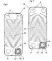
- the separate spaces 11 may be produced by means of rings 31, 32 located between the heat exchanger plates A, B, see Fig 8 .
- rings 31, 32 located between the heat exchanger plates A, B, see Fig 8 .
- the invention also includes combinations of these solutions, i.e. the separate spaces 11 may be delimited by a delimiting surface, provided through the compression-moulding, and by a ring.
- Embodiments having one or several rings 31, 32 may also be combined with a compression-moulded central heat transfer area 10 with corrugations having a suitable pattern, see Fig.
- each heat exchanger plate A, B may be provided with one or two ring grooves for receiving one or both rings 31 and 32, in such a way that each of said rings 31, 32 are provided in a ring groove in the adjacent heat exchanger plate A, B.
- Each such separate space 11 communicates with the first inlet channel 6 and with a respective one of the first plate interspaces 1.
- Each separate space 11 communicates with the first inlet channel 6 via an inlet nozzle forming a throttling having a significantly reduced flow area.
- Each separate space 11 communicates with a respective first plate interspace 1 via an outlet nozzle forming a throttling with a significantly reduced flow area.
- the flow area of the two nozzles is thus significantly reduced in comparison with the flow area of the first inlet channel 6 and in comparison with the flow area of each of the first plate interspaces 1.
- the inlet nozzle is formed by a hole 13 extending through each second heat exchanger plate B.
- the outlet nozzle is formed in a corresponding manner by a hole 14, extending through each second heat exchanger plate B.
- the cooling agent is thus conveyed from the first inlet channel 6 through the holes 13 in the separate spaces 11 and from there through the holes 14 out into the first plate interspaces 1. Thanks to the fact that the holes 13 and 14 thus lie in series with each other, a larger pressure drop may be provided than if merely one throttling is used, since there is a practical delimit for how small the hole may be made. Too small holes lead to a risk that the holes are clogged, for instance in connection with the brazing of the plate package.
- the holes 13 and 14 disclosed may in an easy manner be manufactured with a desired flow area so that a sufficient throttling and thus a sufficient pressure drop is obtained.
- the holes 13 - 14 have a diameter, which may vary with the actual application.
- the holes 13, 15 may have a diameter, which is less than or equal to 9 mm, preferably less than or equal to 7 mm or more preferably less than or equal to 5 mm.
- the diameter of the holes 13, 14 is preferably larger than or equal to 1 mm.
- these rings 31, 32 may include corresponding holes 13, 14 for forming inlet and/or outlet nozzles.
- the inlet nozzle and the outlet nozzle may also be formed in another way than through a respective hole extending through the B-plate.
- a small passage 15, see Fig. 3 between an adjacent first heat exchanger plate A and a second heat exchanger plate B may be provided in connection with the moulding of the second heat exchanger plate B.
- the cooling agent will flow into the separate space 11 via the passage 15 and out of the separate space 11 into the first plate interspace 1 via the hole 14.
- the hole 14 may in an alternative way be designed as a thin passage between the first heat exchanger plate A and the second heat exchanger plate B. In this latter case, the second passages 2 will however receive the cooling agent whereas the first passages 1 receive the fluid cooling the cooling agent.
- the thin passage 15 may have a cross-sectional diameter or cross-sectional size corresponding to the diameter defined above for the holes 13 and 14.
- Each of the heat exchanger plates A, B extends along a central extension plane 16.
- the heat exchanger plates A, B are compression-moulded in such a way that they extend from the central extension plane to an upper plate plane 17 on one side of the central extension plane 16 and to a lower plate plane 18 on the other side of the central extension plane 16.
- Each of the heat exchanger plates B includes an upper surface area 21, which extends around the first porthole 5.
- the upper surface area 21 is located at the level of the upper plate plane 17.
- Each of the second heat exchanger plates B also includes a lower surface area 22, which extends around the first porthole 5 and the upper surface area 21.
- the lower surface area 21 is located at the level of the lower plate plane 18.
- Each of the first heat exchanger plates A includes a lower surface area 23, which extends around the first porthole 5.
- the lower surface area 23 is located at the level of the lower plate plane 18.
- Each of the first heat exchanger plates A also includes an upper surface area 24, which extends around the first porthole 5 and is located between the first porthole 5 and the lower surface area 23.
- the upper surface area 24 is located at the level of the upper plate plane 17.
- the upper surface area 21 of the second heat exchanger plates B is located partly opposite to the lower surface area 23 of the first heat exchanger plates A for forming the separate space 11 between these surface areas 21 and 23. Furthermore, the lower surface area 22 of the second heat exchanger plates B is partly located opposite to the upper surface area 24 of the first heat exchanger plates A. These two surface areas 22 and 24 will thus partly abut each other in the plate package P in such a way that the separate space 11 is closed to the first inlet channel 6 except via the hole 13 or the thin passage 15.
- the hole 13 of the inlet nozzle extends through the lower surface area 22 of the second heat exchanger plates B and is located opposite to the lower surface 23 of the first heat exchanger plates A.
- the hole 14 of the outlet nozzle extends through the upper surface area 21 of the second heat exchanger plates P and is with regard to the central extension 16 displaced in relation to the second surface area 23 of the first heat exchanger plates A.
- the position of the hole 14 in relation to the first heat exchanger plate A is indicated in Fig. 6 . Since the hole 14 is located at the level of the upper plate plane 17, the hole 14 of the uppermost or outermost second heat exchanger plate B will in an easy manner be closed by the upper sealing plate 3 when the plate package P has been mounted.
- the separate space 11 will thus be delimited by the upper surface area 21 of the second heat exchanger plates B and the lower surface area 23 of the first heat exchanger plates A.
- the separate space is delimited to the inlet channels 6 by the lower surface area 22 and the upper surface are 24, which abut each other in the plate package P.
Claims (18)
- Plattenwärmetauscher, umfassend einen Plattenstapel (P), der eine Anzahl von ersten Wärmetauschplatten (A) und eine Anzahl von zweiten Wärmetauschplatten (B) umfasst, die dauerhaft miteinander verbunden und auf eine solche Weise nebeneinander angeordnet sind, dass ein erster Plattenzwischenraum (1) zwischen jedem Paar von benachbarten ersten Wärmetauschplatten (A) und zweiten Wärmetauschplatten (B) gebildet wird sowie ein zweiter Plattenzwischenraum (2) zwischen jedem Paar von benachbarten zweiten Wärmetauschplatten (B) und ersten Wärmetauschplatten (A), wobei die ersten Plattenzwischenräume (1) und die zweiten Plattenzwischenräume (2) voneinander getrennt sind und nebeneinander in abwechselnder Weise im Plattenstapel (P) angeordnet sind,
wobei im Wesentlichen jede Wärmetauschplatte (A, B) mindestens ein erstes Durchgangsloch (5) und ein zweites Durchgangsloch (5) umfasst, wobei die ersten Durchgangslöcher (5) einen ersten Einlasskanal (6) zu den ersten Plattenzwischenräumen (1) und die zweiten Durchgangslöcher (5) einen ersten Auslasskanal (7) aus den ersten Flattenzwischenräumen (1) bilden,
wobei der Plattenstapel einen separater Raum (11) für jeden der ersten Plattenzwischenräume (1) umfasst, wobei dieser Raum (11) den zweiten Plattenzwischenräumen (2) gegenüber geschlossen ist, um
wobei der separate Raum (11) mit dem ersten Einlasskanal (6) über eine Einlassdüse (13, 5) verbunden ist, die eine Drosselung mit einem wesentlich reduzierten Strömungsbereich bildet, und mit dem jeweiligen ersten Plattenzwischenraum (1) über eine Auslassdüse (14), die eine Drosselung mit einem wesentlich reduzierten Strömungsbereich bildet,
dadurch gekennzeichnet,
dass der separate Raum (11) durch Pressformen der Wärmetauschplatten (A, B) hergestellt worden ist,
dass die Einlassdüse durch ein jeweiliges Loch (13) gebildet ist, das sich durch jede der zweiten Wärmetauschplatten (B) erstreckt, und
dass die Auslassdüse von einem jeweiligen Loch (14) gebildet wird, das sich durch jede der zweiten Wärmetauschplatten (B) erstreckt. - Plattenwärmetauscher nach Anspruch 1, dadurch gekennzeichnet, dass der separate Raum in der Nähe des Einlasskanals vorgesehen ist.
- Plattenwärmetauscher nach einem der Ansprüche 1 und 2, dadurch gekennzeichnet, dass der separate Raum (11) zwischen einem jeweiligen Paar benachbarter zweiter Wärmetauschplatten (B) und erster Wärmetauschplatten (A) vorgesehen ist.
- Plattenwärmetauscher nach einem der vorangegangenen Ansprüche, dadurch gekennzeichnet, dass jede der Wärmetauschplatten (A, B) eine mittlere Ausdehnungsebene (16) umfasst sowie eine obere Plattenebene (17) auf einer Seite der mittleren Ausdehnungsebene (16) und eine untere Plattenebene (18) auf der anderen Seite der mittleren Ausdehnungsebene (16).
- Plattenwärmetauscher nach Anspruch 4, dadurch gekennzeichnet, dass jede der zweiten Wärmetauschplatten (B) einen oberen Oberflächenbereich (21) umfasst, der sich um das erste Durchgangsloch (5) herum erstreckt und den separaten Raum (11) begrenzt, wobei sich der obere Oberflächenbereich (21) auf der Höhe der oberen Plattenebene (17) befindet.
- Plattenwärmetauscher nach Anspruch 5, dadurch gekennzeichnet, dass sich das Loch (14) der Auslassdüse durch den oberen Oberflächenbereich (21) erstreckt.
- Plattenwärmetauscher nach Anspruch 6, dadurch gekennzeichnet, dass der Plattenwärmetauscher, eine Endplatte (3) umfasst, die in der Nähe einer der zweiten Wärmetauschplatten (B) auf eine solche Weise vorgesehen ist, dass sie das Loch (14) der Auslassdüse dieser zweiten Wärmetauschplatte (B) schießt.
- Plattenwärmetauscher nach einem der Ansprüche 5 bis 7, dadurch gekennzeichnet, dass jede der zweiten Wärmetauschplatten (B) einen unteren Oberflächenbereich (22) umfasst, der sich um das erste Durchgangsloch (5) herum zwischen dem ersten Durchgangsloch und dem oberen Oberflächenbereich (21) erstreckt, wobei sich der untere Oberflächenbereich (22) auf der Höhe der zweiten unteren Plattenebene (18) befindet.
- Platkenwärmetauscher nach Anspruch 3 und 8, dadurch gekennzeichnet dass sich das Loch (13) der Einlassdüse durch den unteren Oberflächenbereich (22) erstreckt.
- Plattenwärmetauscher nach einem der Ansprüche 4 bis 9, dadurch gekennzeichnet, dass jede der ersten Wärmetauschplatten (A) einen unteren Oberflächenbereich (23) umfasst, der sich um das erste Durchgangsloch (5) herum erstreckt und den separaten Raum (11) begrenzt, wobei sich der untere Oberflächenbereich (23) auf der Höhe der unteren Plattenebene (18) befindet.
- Plattenwärmetauscher nach Anspruch 5 und 10, dadurch gekennzeichnet, dass sich der obere Oberflächenbereich (21) der zweiten Wärmetauschplatten (B) teilweise gegenüber dem unteren Oberflächenbereich (23) der ersten Wärmetauschplatten (A) befindet, um den separaten Raum (11) zwischen diesen Oberflächenbereichen (21, 23) zu bilden.
- Plattenwärmetauscher nach Anspruch 11, dadurch gekennzeichnet, dass sich die Einlassdüse gegenüber dem unteren Oberflächenbereich (23) der ersten Wärmetauschplatten (A) befindet.
- Plattenwärmetauscher nach Anspruch 12, dadurch gekennzeichnet, dass die Auslassdüse im Hinblick auf die Ausdehnungsebene (16) relativ zum unteren Oberflächenbereich (23) der ersten Wärmetauschplatten (A) verschoben ist.
- Plattenwärmetauscher nach einem der Ansprüche 10 bis 13, dadurch gekennzeichnet, dass jede der ersten Wärmetauschplatten (A) einen oberen Oberflächenbereich (24) umfasst, der sich um das erste Durchgangsloch (5) herum zwischen dem ersten Durchgangsloch und dem unteren Oberflächenbereich (23) erstreckt, wobei sich der obere Oberflächenbereich (24) auf der Höhe der oberen Plattenebene (17) befindet.
- Plattenwärmetauscher nach Anspruch 8 und 14, dadurch gekennzeichnet, dass sich der untere Oberflächenbereich (22) der zweiten Wärmetauschplatten (B) teilweise gegenüber dem oberen Oberflächenbereich (24) der ersten Wärmetauschplatten (A) befindet, wobei diese beiden Oberflächenbereiche (22, 24) teilweise im Plattenstapel (P) aneinander anstoßen.
- Plattenwärmetauscher nach einem der vorangegangenen Ansprüche, dadurch gekennzeichnet, dass die ersten Plattenzwischenräume (1) erste Durchgänge für ein Kühlmittel bilden und die zweiten Plattenzwischenräume (2) zweite Durchgänge für ein Fluidum, das vom Kühlmittel gekühlt wird.
- Plattenwärmetauscher nach einem der vorangegangenen Ansprüche, dadurch gekennzeichnet, dass im Wesentlichen jede Wärmetauschplatte (A, B) mindestens ein drittes Durchgangsloch (5) und ein viertes Durchgangsloch (5) aufweist, die sich durch den Plattenstapel erstrecken, wobei die dritten Durchgangslöcher (5) einen zweiten Einlasskanal (8) zu den zweiten Plattenzwischenräumen (2) und die vierten Durchgangslöcher (5) einen zweiten Auslasskanal (9) aus den zweiten Plattenzwischenräumen (2) bilden.
- Plattenwärmetauscher nach einem der vorangegangenen Ansprüche, dadurch gekennzeichnet, dass die Wärmetauschplatten (A, B) im Plattenstapel (P) miteinander durch Löten verbunden sind.
Applications Claiming Priority (2)
| Application Number | Priority Date | Filing Date | Title |
|---|---|---|---|
| SE0400017A SE526409C2 (sv) | 2004-01-09 | 2004-01-09 | Plattvärmeväxlare |
| PCT/SE2004/001976 WO2005066572A1 (en) | 2004-01-09 | 2004-12-22 | A plate heat exchanger |
Publications (2)
| Publication Number | Publication Date |
|---|---|
| EP1702193A1 EP1702193A1 (de) | 2006-09-20 |
| EP1702193B1 true EP1702193B1 (de) | 2011-03-16 |
Family
ID=31493002
Family Applications (1)
| Application Number | Title | Priority Date | Filing Date |
|---|---|---|---|
| EP04809149A Active EP1702193B1 (de) | 2004-01-09 | 2004-12-22 | Plattenwärmetauscher |
Country Status (9)
| Country | Link |
|---|---|
| US (1) | US7690420B2 (de) |
| EP (1) | EP1702193B1 (de) |
| JP (1) | JP4607904B2 (de) |
| CN (1) | CN100483063C (de) |
| AT (1) | ATE502274T1 (de) |
| DE (1) | DE602004031877D1 (de) |
| ES (1) | ES2359635T3 (de) |
| SE (1) | SE526409C2 (de) |
| WO (1) | WO2005066572A1 (de) |
Families Citing this family (15)
| Publication number | Priority date | Publication date | Assignee | Title |
|---|---|---|---|---|
| SE532524C2 (sv) * | 2008-06-13 | 2010-02-16 | Alfa Laval Corp Ab | Värmeväxlarplatta samt värmeväxlarmontage innefattandes fyra plattor |
| JP5940970B2 (ja) * | 2012-02-10 | 2016-06-29 | 株式会社ティラド | 積層型熱交換器 |
| CN103808189A (zh) * | 2012-11-13 | 2014-05-21 | 浙江鸿远制冷设备有限公司 | 板式换热器用于分配蒸发液的换热波纹板片 |
| US9372018B2 (en) * | 2013-06-05 | 2016-06-21 | Hamilton Sundstrand Corporation | Evaporator heat exchanger |
| CN105793662B (zh) * | 2013-12-10 | 2020-03-10 | 舒瑞普国际股份公司 | 具有改进的流动的热交换器 |
| CN103940267B (zh) * | 2014-04-10 | 2016-06-01 | 浙江峰煌热交换器有限公司 | 板式换热器及其流体分配器、板片 |
| CN106415183B (zh) * | 2014-05-27 | 2019-03-15 | 舒瑞普国际股份公司 | 热交换器 |
| CN105466255B (zh) * | 2014-09-05 | 2019-06-21 | 丹佛斯微通道换热器(嘉兴)有限公司 | 板式换热器 |
| SE541284C2 (en) * | 2016-05-30 | 2019-06-11 | Alfa Laval Corp Ab | A plate heat exchanger |
| SE541355C2 (en) | 2016-12-22 | 2019-08-13 | Alfa Laval Corp Ab | A plate heat exchanger with six ports for three different media |
| CN111380386B (zh) * | 2018-12-28 | 2021-08-27 | 丹佛斯有限公司 | 多回路板式换热器 |
| SE543419C2 (en) * | 2019-02-26 | 2021-01-12 | Alfa Laval Corp Ab | A heat exchanger plate and a plate heat exchanger |
| JP7247717B2 (ja) * | 2019-04-01 | 2023-03-29 | 株式会社デンソー | 熱交換器 |
| US11920876B2 (en) * | 2020-12-10 | 2024-03-05 | Danfoss Micro Channel Heat Exchanger (Jiaxing) Co., Ltd. | Distributor for plate heat exchanger and plate heat exchanger |
| SE2150186A1 (en) * | 2021-02-22 | 2022-08-23 | Swep Int Ab | A brazed plate heat exchanger |
Citations (1)
| Publication number | Priority date | Publication date | Assignee | Title |
|---|---|---|---|---|
| JP2001280888A (ja) * | 2000-03-31 | 2001-10-10 | Hisaka Works Ltd | プレート式熱交換器 |
Family Cites Families (13)
| Publication number | Priority date | Publication date | Assignee | Title |
|---|---|---|---|---|
| FR958699A (de) * | 1942-05-22 | 1950-03-17 | ||
| US2550339A (en) * | 1948-08-03 | 1951-04-24 | York Corp | Plate type heat exchanger |
| US3444926A (en) * | 1967-11-28 | 1969-05-20 | Rosenblads Patenter Ab | Arrangement in heat exchangers of the plate type |
| AT380739B (de) * | 1984-03-14 | 1986-06-25 | Helmut Ing Fischer | Zerlegbarer plattenwaermeaustauscher und presswerkzeug zur herstellung von waermeaustauschplatten dieses waermeaustauschers |
| DE3600656A1 (de) | 1986-01-11 | 1987-07-16 | Gea Ahlborn Gmbh & Co Kg | Waermeaustauscher |
| SE502984C2 (sv) * | 1993-06-17 | 1996-03-04 | Alfa Laval Thermal Ab | Plattvärmeväxlare med speciellt utformade portpartier |
| IT1276990B1 (it) | 1995-10-24 | 1997-11-03 | Tetra Laval Holdings & Finance | Scambiatore di calore a piastre |
| SE508474C2 (sv) * | 1997-02-14 | 1998-10-12 | Alfa Laval Ab | Sätt att framställa värmeväxlingsplattor; sortiment av värmeväxlingsplattor; och en plattvärmeväxlare innefattande värmeväxlingsplattor ingående i sortimentet |
| JPH10267580A (ja) * | 1997-03-27 | 1998-10-09 | Hisaka Works Ltd | プレート式熱交換器 |
| JPH10267581A (ja) * | 1997-03-28 | 1998-10-09 | Hisaka Works Ltd | プレート式熱交換器 |
| US20010030043A1 (en) * | 1999-05-11 | 2001-10-18 | William T. Gleisle | Brazed plate heat exchanger utilizing metal gaskets and method for making same |
| US6478081B1 (en) * | 1999-08-04 | 2002-11-12 | Apv North America Inc. | Plate heat exchanger |
| JP2002107090A (ja) * | 2000-09-29 | 2002-04-10 | Hisaka Works Ltd | プレート式熱交換器及び製造方法 |
-
2004
- 2004-01-09 SE SE0400017A patent/SE526409C2/sv not_active IP Right Cessation
- 2004-12-22 ES ES04809149T patent/ES2359635T3/es active Active
- 2004-12-22 EP EP04809149A patent/EP1702193B1/de active Active
- 2004-12-22 JP JP2006549181A patent/JP4607904B2/ja active Active
- 2004-12-22 US US10/581,351 patent/US7690420B2/en active Active
- 2004-12-22 WO PCT/SE2004/001976 patent/WO2005066572A1/en not_active Application Discontinuation
- 2004-12-22 AT AT04809149T patent/ATE502274T1/de not_active IP Right Cessation
- 2004-12-22 CN CNB200480040182XA patent/CN100483063C/zh active Active
- 2004-12-22 DE DE602004031877T patent/DE602004031877D1/de active Active
Patent Citations (1)
| Publication number | Priority date | Publication date | Assignee | Title |
|---|---|---|---|---|
| JP2001280888A (ja) * | 2000-03-31 | 2001-10-10 | Hisaka Works Ltd | プレート式熱交換器 |
Also Published As
| Publication number | Publication date |
|---|---|
| ATE502274T1 (de) | 2011-04-15 |
| SE0400017L (sv) | 2005-07-10 |
| CN1902456A (zh) | 2007-01-24 |
| JP2007518056A (ja) | 2007-07-05 |
| US20080283231A1 (en) | 2008-11-20 |
| EP1702193A1 (de) | 2006-09-20 |
| WO2005066572A1 (en) | 2005-07-21 |
| SE526409C2 (sv) | 2005-09-06 |
| US7690420B2 (en) | 2010-04-06 |
| JP4607904B2 (ja) | 2011-01-05 |
| SE0400017D0 (sv) | 2004-01-09 |
| DE602004031877D1 (de) | 2011-04-28 |
| CN100483063C (zh) | 2009-04-29 |
| ES2359635T3 (es) | 2011-05-25 |
Similar Documents
| Publication | Publication Date | Title |
|---|---|---|
| EP1998132B1 (de) | Rippenplattenwärmetauscher | |
| EP1702193B1 (de) | Plattenwärmetauscher | |
| US6164371A (en) | Plate heat exchanger for three heat exchanging fluids | |
| US6199626B1 (en) | Self-enclosing heat exchangers | |
| US6305466B1 (en) | Three circuit plate heat exchanger | |
| US5924484A (en) | Plate heat exchanger | |
| EP1484567B1 (de) | Wärmetauscher mit paralleler Fluidströmung | |
| EP2267391B1 (de) | Asymmetrischer Wärmetauscher | |
| EP2674714B1 (de) | Plattenwärmetauscher mit Einspritzdüsen | |
| JPH073315B2 (ja) | 熱交換器 | |
| EP2002195B1 (de) | Plattenwärmeaustauscher mit verstärkungsplatten ausserhalb der äussersten wärmetauscherplatten | |
| US7121331B2 (en) | Heat exchanger | |
| CN110073163B (zh) | 板式热交换器 | |
| EP2815198B1 (de) | Plattenwärmetauscher mit verbesserter festigkeit im verbindungsbereich | |
| US7204297B2 (en) | Plate-type heat exchanger with double-walled heat transfer plates | |
| WO2003010482A1 (en) | Heat transfer plate, plate pack and plate heat exchanger | |
| JP7057654B2 (ja) | オイルクーラ | |
| JP6986431B2 (ja) | オイルクーラ | |
| JP6929765B2 (ja) | オイルクーラ | |
| SE9904786D0 (sv) | Plattvärmeväxlare |
Legal Events
| Date | Code | Title | Description |
|---|---|---|---|
| PUAI | Public reference made under article 153(3) epc to a published international application that has entered the european phase |
Free format text: ORIGINAL CODE: 0009012 |
|
| 17P | Request for examination filed |
Effective date: 20060531 |
|
| AK | Designated contracting states |
Kind code of ref document: A1 Designated state(s): AT BE BG CH CY CZ DE DK EE ES FI FR GB GR HU IE IS IT LI LT LU MC NL PL PT RO SE SI SK TR |
|
| DAX | Request for extension of the european patent (deleted) | ||
| TPAC | Observations filed by third parties |
Free format text: ORIGINAL CODE: EPIDOSNTIPA |
|
| 17Q | First examination report despatched |
Effective date: 20100208 |
|
| GRAP | Despatch of communication of intention to grant a patent |
Free format text: ORIGINAL CODE: EPIDOSNIGR1 |
|
| RIN1 | Information on inventor provided before grant (corrected) |
Inventor name: HOERTE, TOBIAS |
|
| GRAS | Grant fee paid |
Free format text: ORIGINAL CODE: EPIDOSNIGR3 |
|
| GRAA | (expected) grant |
Free format text: ORIGINAL CODE: 0009210 |
|
| AK | Designated contracting states |
Kind code of ref document: B1 Designated state(s): AT BE BG CH CY CZ DE DK EE ES FI FR GB GR HU IE IS IT LI LT LU MC NL PL PT RO SE SI SK TR |
|
| REG | Reference to a national code |
Ref country code: GB Ref legal event code: FG4D |
|
| REG | Reference to a national code |
Ref country code: CH Ref legal event code: EP |
|
| REG | Reference to a national code |
Ref country code: IE Ref legal event code: FG4D |
|
| REF | Corresponds to: |
Ref document number: 602004031877 Country of ref document: DE Date of ref document: 20110428 Kind code of ref document: P |
|
| REG | Reference to a national code |
Ref country code: DE Ref legal event code: R096 Ref document number: 602004031877 Country of ref document: DE Effective date: 20110428 |
|
| REG | Reference to a national code |
Ref country code: ES Ref legal event code: FG2A Ref document number: 2359635 Country of ref document: ES Kind code of ref document: T3 Effective date: 20110525 |
|
| REG | Reference to a national code |
Ref country code: NL Ref legal event code: VDEP Effective date: 20110316 |
|
| PG25 | Lapsed in a contracting state [announced via postgrant information from national office to epo] |
Ref country code: GR Free format text: LAPSE BECAUSE OF FAILURE TO SUBMIT A TRANSLATION OF THE DESCRIPTION OR TO PAY THE FEE WITHIN THE PRESCRIBED TIME-LIMIT Effective date: 20110617 Ref country code: LT Free format text: LAPSE BECAUSE OF FAILURE TO SUBMIT A TRANSLATION OF THE DESCRIPTION OR TO PAY THE FEE WITHIN THE PRESCRIBED TIME-LIMIT Effective date: 20110316 Ref country code: SE Free format text: LAPSE BECAUSE OF FAILURE TO SUBMIT A TRANSLATION OF THE DESCRIPTION OR TO PAY THE FEE WITHIN THE PRESCRIBED TIME-LIMIT Effective date: 20110316 |
|
| LTIE | Lt: invalidation of european patent or patent extension |
Effective date: 20110316 |
|
| PG25 | Lapsed in a contracting state [announced via postgrant information from national office to epo] |
Ref country code: BG Free format text: LAPSE BECAUSE OF FAILURE TO SUBMIT A TRANSLATION OF THE DESCRIPTION OR TO PAY THE FEE WITHIN THE PRESCRIBED TIME-LIMIT Effective date: 20110616 Ref country code: CY Free format text: LAPSE BECAUSE OF FAILURE TO SUBMIT A TRANSLATION OF THE DESCRIPTION OR TO PAY THE FEE WITHIN THE PRESCRIBED TIME-LIMIT Effective date: 20110316 Ref country code: FI Free format text: LAPSE BECAUSE OF FAILURE TO SUBMIT A TRANSLATION OF THE DESCRIPTION OR TO PAY THE FEE WITHIN THE PRESCRIBED TIME-LIMIT Effective date: 20110316 Ref country code: SI Free format text: LAPSE BECAUSE OF FAILURE TO SUBMIT A TRANSLATION OF THE DESCRIPTION OR TO PAY THE FEE WITHIN THE PRESCRIBED TIME-LIMIT Effective date: 20110316 Ref country code: AT Free format text: LAPSE BECAUSE OF FAILURE TO SUBMIT A TRANSLATION OF THE DESCRIPTION OR TO PAY THE FEE WITHIN THE PRESCRIBED TIME-LIMIT Effective date: 20110316 |
|
| PG25 | Lapsed in a contracting state [announced via postgrant information from national office to epo] |
Ref country code: BE Free format text: LAPSE BECAUSE OF FAILURE TO SUBMIT A TRANSLATION OF THE DESCRIPTION OR TO PAY THE FEE WITHIN THE PRESCRIBED TIME-LIMIT Effective date: 20110316 |
|
| PG25 | Lapsed in a contracting state [announced via postgrant information from national office to epo] |
Ref country code: EE Free format text: LAPSE BECAUSE OF FAILURE TO SUBMIT A TRANSLATION OF THE DESCRIPTION OR TO PAY THE FEE WITHIN THE PRESCRIBED TIME-LIMIT Effective date: 20110316 Ref country code: PT Free format text: LAPSE BECAUSE OF FAILURE TO SUBMIT A TRANSLATION OF THE DESCRIPTION OR TO PAY THE FEE WITHIN THE PRESCRIBED TIME-LIMIT Effective date: 20110718 |
|
| PG25 | Lapsed in a contracting state [announced via postgrant information from national office to epo] |
Ref country code: IS Free format text: LAPSE BECAUSE OF FAILURE TO SUBMIT A TRANSLATION OF THE DESCRIPTION OR TO PAY THE FEE WITHIN THE PRESCRIBED TIME-LIMIT Effective date: 20110716 Ref country code: CZ Free format text: LAPSE BECAUSE OF FAILURE TO SUBMIT A TRANSLATION OF THE DESCRIPTION OR TO PAY THE FEE WITHIN THE PRESCRIBED TIME-LIMIT Effective date: 20110316 Ref country code: RO Free format text: LAPSE BECAUSE OF FAILURE TO SUBMIT A TRANSLATION OF THE DESCRIPTION OR TO PAY THE FEE WITHIN THE PRESCRIBED TIME-LIMIT Effective date: 20110316 Ref country code: SK Free format text: LAPSE BECAUSE OF FAILURE TO SUBMIT A TRANSLATION OF THE DESCRIPTION OR TO PAY THE FEE WITHIN THE PRESCRIBED TIME-LIMIT Effective date: 20110316 |
|
| PG25 | Lapsed in a contracting state [announced via postgrant information from national office to epo] |
Ref country code: NL Free format text: LAPSE BECAUSE OF FAILURE TO SUBMIT A TRANSLATION OF THE DESCRIPTION OR TO PAY THE FEE WITHIN THE PRESCRIBED TIME-LIMIT Effective date: 20110316 |
|
| PLBE | No opposition filed within time limit |
Free format text: ORIGINAL CODE: 0009261 |
|
| STAA | Information on the status of an ep patent application or granted ep patent |
Free format text: STATUS: NO OPPOSITION FILED WITHIN TIME LIMIT |
|
| 26N | No opposition filed |
Effective date: 20111219 |
|
| PG25 | Lapsed in a contracting state [announced via postgrant information from national office to epo] |
Ref country code: DK Free format text: LAPSE BECAUSE OF FAILURE TO SUBMIT A TRANSLATION OF THE DESCRIPTION OR TO PAY THE FEE WITHIN THE PRESCRIBED TIME-LIMIT Effective date: 20110316 Ref country code: PL Free format text: LAPSE BECAUSE OF FAILURE TO SUBMIT A TRANSLATION OF THE DESCRIPTION OR TO PAY THE FEE WITHIN THE PRESCRIBED TIME-LIMIT Effective date: 20110316 |
|
| REG | Reference to a national code |
Ref country code: DE Ref legal event code: R097 Ref document number: 602004031877 Country of ref document: DE Effective date: 20111219 |
|
| PG25 | Lapsed in a contracting state [announced via postgrant information from national office to epo] |
Ref country code: MC Free format text: LAPSE BECAUSE OF NON-PAYMENT OF DUE FEES Effective date: 20111231 |
|
| REG | Reference to a national code |
Ref country code: CH Ref legal event code: PL |
|
| REG | Reference to a national code |
Ref country code: IE Ref legal event code: MM4A |
|
| PG25 | Lapsed in a contracting state [announced via postgrant information from national office to epo] |
Ref country code: CH Free format text: LAPSE BECAUSE OF NON-PAYMENT OF DUE FEES Effective date: 20111231 Ref country code: IE Free format text: LAPSE BECAUSE OF NON-PAYMENT OF DUE FEES Effective date: 20111222 Ref country code: LI Free format text: LAPSE BECAUSE OF NON-PAYMENT OF DUE FEES Effective date: 20111231 |
|
| PG25 | Lapsed in a contracting state [announced via postgrant information from national office to epo] |
Ref country code: LU Free format text: LAPSE BECAUSE OF NON-PAYMENT OF DUE FEES Effective date: 20111222 |
|
| PG25 | Lapsed in a contracting state [announced via postgrant information from national office to epo] |
Ref country code: TR Free format text: LAPSE BECAUSE OF FAILURE TO SUBMIT A TRANSLATION OF THE DESCRIPTION OR TO PAY THE FEE WITHIN THE PRESCRIBED TIME-LIMIT Effective date: 20110316 |
|
| PG25 | Lapsed in a contracting state [announced via postgrant information from national office to epo] |
Ref country code: HU Free format text: LAPSE BECAUSE OF FAILURE TO SUBMIT A TRANSLATION OF THE DESCRIPTION OR TO PAY THE FEE WITHIN THE PRESCRIBED TIME-LIMIT Effective date: 20110316 |
|
| REG | Reference to a national code |
Ref country code: FR Ref legal event code: PLFP Year of fee payment: 12 |
|
| REG | Reference to a national code |
Ref country code: FR Ref legal event code: PLFP Year of fee payment: 13 |
|
| REG | Reference to a national code |
Ref country code: FR Ref legal event code: PLFP Year of fee payment: 14 |
|
| PGFP | Annual fee paid to national office [announced via postgrant information from national office to epo] |
Ref country code: ES Payment date: 20230110 Year of fee payment: 19 |
|
| REG | Reference to a national code |
Ref country code: DE Ref legal event code: R082 Ref document number: 602004031877 Country of ref document: DE Representative=s name: MEISSNER BOLTE PATENTANWAELTE RECHTSANWAELTE P, DE |
|
| P01 | Opt-out of the competence of the unified patent court (upc) registered |
Effective date: 20230412 |
|
| PGFP | Annual fee paid to national office [announced via postgrant information from national office to epo] |
Ref country code: GB Payment date: 20231102 Year of fee payment: 20 |
|
| PGFP | Annual fee paid to national office [announced via postgrant information from national office to epo] |
Ref country code: IT Payment date: 20231110 Year of fee payment: 20 Ref country code: FR Payment date: 20231108 Year of fee payment: 20 Ref country code: DE Payment date: 20231024 Year of fee payment: 20 |
|
| PGFP | Annual fee paid to national office [announced via postgrant information from national office to epo] |
Ref country code: ES Payment date: 20240115 Year of fee payment: 20 |