EP2002195B1 - Plattenwärmeaustauscher mit verstärkungsplatten ausserhalb der äussersten wärmetauscherplatten - Google Patents
Plattenwärmeaustauscher mit verstärkungsplatten ausserhalb der äussersten wärmetauscherplatten Download PDFInfo
- Publication number
- EP2002195B1 EP2002195B1 EP07748359.2A EP07748359A EP2002195B1 EP 2002195 B1 EP2002195 B1 EP 2002195B1 EP 07748359 A EP07748359 A EP 07748359A EP 2002195 B1 EP2002195 B1 EP 2002195B1
- Authority
- EP
- European Patent Office
- Prior art keywords
- plate
- heat exchanger
- strengthening
- plates
- ports
- Prior art date
- Legal status (The legal status is an assumption and is not a legal conclusion. Google has not performed a legal analysis and makes no representation as to the accuracy of the status listed.)
- Not-in-force
Links
- 238000005728 strengthening Methods 0.000 title claims description 87
- 230000008018 melting Effects 0.000 claims description 3
- 238000002844 melting Methods 0.000 claims description 3
- 239000007769 metal material Substances 0.000 claims description 3
- 238000003466 welding Methods 0.000 description 5
- 238000005219 brazing Methods 0.000 description 4
- 238000004519 manufacturing process Methods 0.000 description 3
- 239000000463 material Substances 0.000 description 3
- 238000005452 bending Methods 0.000 description 2
- 238000000748 compression moulding Methods 0.000 description 2
- 238000004026 adhesive bonding Methods 0.000 description 1
- 230000001419 dependent effect Effects 0.000 description 1
Images

Classifications
-
- F—MECHANICAL ENGINEERING; LIGHTING; HEATING; WEAPONS; BLASTING
- F28—HEAT EXCHANGE IN GENERAL
- F28D—HEAT-EXCHANGE APPARATUS, NOT PROVIDED FOR IN ANOTHER SUBCLASS, IN WHICH THE HEAT-EXCHANGE MEDIA DO NOT COME INTO DIRECT CONTACT
- F28D9/00—Heat-exchange apparatus having stationary plate-like or laminated conduit assemblies for both heat-exchange media, the media being in contact with different sides of a conduit wall
- F28D9/0031—Heat-exchange apparatus having stationary plate-like or laminated conduit assemblies for both heat-exchange media, the media being in contact with different sides of a conduit wall the conduits for one heat-exchange medium being formed by paired plates touching each other
- F28D9/0043—Heat-exchange apparatus having stationary plate-like or laminated conduit assemblies for both heat-exchange media, the media being in contact with different sides of a conduit wall the conduits for one heat-exchange medium being formed by paired plates touching each other the plates having openings therein for circulation of at least one heat-exchange medium from one conduit to another
- F28D9/005—Heat-exchange apparatus having stationary plate-like or laminated conduit assemblies for both heat-exchange media, the media being in contact with different sides of a conduit wall the conduits for one heat-exchange medium being formed by paired plates touching each other the plates having openings therein for circulation of at least one heat-exchange medium from one conduit to another the plates having openings therein for both heat-exchange media
-
- F—MECHANICAL ENGINEERING; LIGHTING; HEATING; WEAPONS; BLASTING
- F28—HEAT EXCHANGE IN GENERAL
- F28F—DETAILS OF HEAT-EXCHANGE AND HEAT-TRANSFER APPARATUS, OF GENERAL APPLICATION
- F28F9/00—Casings; Header boxes; Auxiliary supports for elements; Auxiliary members within casings
- F28F9/02—Header boxes; End plates
-
- F—MECHANICAL ENGINEERING; LIGHTING; HEATING; WEAPONS; BLASTING
- F28—HEAT EXCHANGE IN GENERAL
- F28F—DETAILS OF HEAT-EXCHANGE AND HEAT-TRANSFER APPARATUS, OF GENERAL APPLICATION
- F28F2225/00—Reinforcing means
-
- F—MECHANICAL ENGINEERING; LIGHTING; HEATING; WEAPONS; BLASTING
- F28—HEAT EXCHANGE IN GENERAL
- F28F—DETAILS OF HEAT-EXCHANGE AND HEAT-TRANSFER APPARATUS, OF GENERAL APPLICATION
- F28F3/00—Plate-like or laminated elements; Assemblies of plate-like or laminated elements
- F28F3/08—Elements constructed for building-up into stacks, e.g. capable of being taken apart for cleaning
- F28F3/083—Elements constructed for building-up into stacks, e.g. capable of being taken apart for cleaning capable of being taken apart
-
- Y—GENERAL TAGGING OF NEW TECHNOLOGICAL DEVELOPMENTS; GENERAL TAGGING OF CROSS-SECTIONAL TECHNOLOGIES SPANNING OVER SEVERAL SECTIONS OF THE IPC; TECHNICAL SUBJECTS COVERED BY FORMER USPC CROSS-REFERENCE ART COLLECTIONS [XRACs] AND DIGESTS
- Y10—TECHNICAL SUBJECTS COVERED BY FORMER USPC
- Y10S—TECHNICAL SUBJECTS COVERED BY FORMER USPC CROSS-REFERENCE ART COLLECTIONS [XRACs] AND DIGESTS
- Y10S165/00—Heat exchange
- Y10S165/906—Reinforcement
-
- Y—GENERAL TAGGING OF NEW TECHNOLOGICAL DEVELOPMENTS; GENERAL TAGGING OF CROSS-SECTIONAL TECHNOLOGIES SPANNING OVER SEVERAL SECTIONS OF THE IPC; TECHNICAL SUBJECTS COVERED BY FORMER USPC CROSS-REFERENCE ART COLLECTIONS [XRACs] AND DIGESTS
- Y10—TECHNICAL SUBJECTS COVERED BY FORMER USPC
- Y10S—TECHNICAL SUBJECTS COVERED BY FORMER USPC CROSS-REFERENCE ART COLLECTIONS [XRACs] AND DIGESTS
- Y10S165/00—Heat exchange
- Y10S165/916—Oil cooler
Definitions
- the invention refers to a plate heat exchanger comprising a plate package with plates according to the preamble of claim 1, see EP-347961 , DE20010816U or US2006/053833 .
- a high strength is required. This is important when the working pressure of one or both of the media conveyed through the plate heat exchanger is high or when the working pressure for one or both of the media various over time.
- Plate heat exchangers are pressure tested before delivery. It is desirable to achieve such a strength and rigidity of the plate heat exchanger that the plastic deformation in connection with the pressure testing is as small as possible. In order to meet requirements of higher strength it is known to use thicker end or strengthening plates, i.e.
- These strengthening plates may also be designated as adapter plates or frame and pressure plates. It is also known to use sheets, washers or thick plane plates as strengthening plates. Such sheets, washers or thick plane plates may also be provided outside the frame and/or pressure plates.
- a disadvantage of such additional plates, washers or the like is that the manufacturing becomes more complicated since more components have to be fixed when the plate heat exchanger is produced, for instance when it is brazed.
- Another disadvantage of thicker strengthening plates with more material is that the thermal "slowness" increases for this strengthening plates. Due to this higher thermal slowness of the strengthening plates, a reduced thermal fatigue performance of the plate heat exchanger is obtained, in particular in the heat exchanger plates which are provided most adjacent inside the strengthening plates. Since the heat exchanger plates are manufactured of a thinner material, they will more rapidly be adapted to the temperature of the media, which results in an undesired temperature difference between the heat exchanger plates and the strengthening plates, and thus to thermally dependent stresses.
- US-A-4,987,955 discloses a plate heat exchanger comprising a plurality of plates extending in parallel with a main extension plane.
- the plates comprise a plurality of heat exchanger plates and at least one strengthening plate.
- the heat exchanger plates are provided beside each other and form a plate package with first plate interspaces for a first medium and second plate interspaces for a second medium.
- Each of the heat exchanger plates has four portholes which form ports extending through the plate package.
- the heat exchanger plates comprises an outermost heat exchanger plate at one side of the plate package and an outermost heat exchanger plate at an opposite side of the plate package.
- Two of the plate interspaces in the plate package form a respective outermost plate interspace at a respective side of the plate package, which are delimited outwardly by a respective one of the outermost heat exchanger plates.
- the strengthening plate is provided beside and outside one of the outermost heat exchanger plates.
- US2005/039895 refers to a heat exchanger comprising consecutively arranged tubes defining one flow path for one heat exchanging media in the plate interspaces defined by the tubes. Each tube is formed by two heat exchanger plates. Each plate comprises four portholes, wherein the portholes form inlets and outlets for one and the same heat exchanging media. The tubes are arranged with a distance from each other. The second medium, i.e. air, is intended to flow in the space formed between the tubes.
- US2005/039895 does not refer to a plate heat exchanger in the conventional sense, but to a heat exchanger or radiator having tubes formed by plates.
- JP-H10-170101 discloses a similar heat exchanger as US2005/039895 comprising tubes formed by two adjacent plates and provided beside each other. Also in this case, the second medium is intended to flow in the space between the tubes.
- the object of the present invention is to remedy the disadvantages mentioned above and to provide a plate heat exchanger with a high strength. Furthermore, it is aimed at a plate heat exchanger that can be manufactured at low costs. In particular, it is aimed at a permanently joined plate heat exchanger with a high strength.
- the plate heat exchanger initially defined which is characterized by the characterizing features of claim 1.
- One such strengthening plate with a strengthening pattern may be made thinner than a completely plane plate and at the same time resist the forces acting on the plate package.
- such a strengthening pattern may counteract the force which, due to a high pressure of any of the media, tends to deform the heat exchanger plates outwardly.
- the depressions extend in a plane which is perpendicular to this force tending to deform the heat exchanger plates outwardly.
- the depressions may be obtained in connection with the compression-moulding of the strengthening plate.
- the depressions are longer than wide and may obtain a significant length in said plane being perpendicular to this force tending to deform the heat exchanger plates outwardly.
- the plate heat exchanger are permanently joined to each other.
- the plates are permanently joined to each other through melting of a metallic material, such as through brazing and/or welding.
- the plates also may be glued to each other.
- the invention also is applicable to plate heat exchangers provided with gaskets, where the heat exchanger plates are compressed against each other by means of suitable tie members, such as tie bolts.
- the strengthening pattern is design to coact with a press pattern of the outermost heat exchanger plate which is provided beside the strengthening plate in such a way that the strengthening plate is positioned in a defined position in relation to the outermost heat exchanger plate.
- the manufacturing of the plate heat exchanger is facilitated since the strengthening plate does not have to be attached to the outermost heat exchanger plate, for instance through welding, before the brazing of the plate heat exchanger.
- the strengthening plate may be locked in the desired position in relation to the outermost heat exchanger plate and the plate package.
- the straight extension of the depressions may, as indicated above, extend in parallel with a plane being perpendicular to the force tending to deform the heat exchanger plates. This plane is perpendicular, or substantially perpendicular, to the extension plane.
- the depressions extend between said two ports. Especially between the ports, forces, which act outwardly from the plate package in a normal direction with respect to the extension plane, appear. Depressions in this area may in an efficient manner counteract such forces.
- the main zone has a substantially plane extension, wherein the strengthening pattern extends outwardly from the plane extension.
- the main zone has an area which forms at least a larger part of the area of the strengthening plate.
- the area of the strengthening plate may be somewhat less than the area of the heat exchanger plates.
- the strengthening plate comprises at least two portholes, which are concentric to a respective port of said two ports. Consequently, the portholes of the strengthening plate may form a part of the ports of the plate heat exchanger. It is also to be noted that the strengthening plate may be continuous, i.e. comprising no portholes since the inlet and/or the outlet for the ports in question may be located on the side of the plate package which faces away from the strengthening plate.
- the strengthening plate comprises two strengthening patterns, which are provided in the proximity of a respective pair of ports and which each comprises several depressions extending outwardly from the heat exchanger plates, wherein said depressions are elongated along the extension plane and seen in a normal direction to the extension plane and wherein said depressions have a substantially straight extension and extend between the ports of said respective pair of ports.
- the strengthening plate may then comprise at least four portholes, which are concentric to a respective port of the ports of the plate package.
- each heat exchanger plates comprises a heat exchanger zone and an outer edge zone, which extends around the heat exchanger zone, wherein the strengthening plate has such a size that it is contained within the outer edge zone.
- the outer edge zone may comprise a surrounding flange which extends outwardly from the extension plane.
- the area of the strengthening plate is thus less than the area of the heat exchanger plates, and the strengthening plate may then advantageously be substantially plane in the sense that it does not comprise any flange as comprised by the heat exchanger plates.
- the strengthening plate may in principle have the same area as the heat exchanger plates and be provided with a surrounding flange in the same way as the heat exchanger plates.
- the plates comprise a further strengthening plate which is provided outside the second of the outermost heat exchanger plates, wherein the further strengthening plate has a main zone, which extends in parallel with the extension plane and comprises a strengthening pattern, which is provided in the proximity of two of the ports and comprises at least one depression extending outwardly from the heat exchanger plates. Consequently, the plate package may on both sides comprise a strengthening plate for strengthening of the zone around the ports.
- the further strengthening plate may in principle have the same design as the above described strengthening plate.
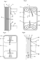
- Figs. 1-4 disclose a first embodiment of a plate heat exchanger according to the invention.
- the plate heat exchanger comprises a plurality of plates, which each extends substantially in parallel with a main extension plane p.
- the plates comprises in the first embodiment a plurality of heat exchanger plates 1 and at least one strengthening plate 2.
- the plate heat exchanger comprises four strengthening plates 2.
- the plates comprises a frame plate 3 and a pressure plate 4, which are provided on a respective side of the heat exchanger plates 1.
- the heat exchanger plates 1 form a plate package with first plate interspaces 5 for a first medium and second interspaces 6 for a second medium.
- the plate interspaces 5, 6 are provided in an alternating order in such a way that every second plate interspace is a first plate interspace 5 and the remaining plate interspaces are second plate interspaces 6, see Fig. 4 .
- Each heat exchanger plate 1 comprises four portholes 7 which form ports 8 extending through the plate package and forming inlets and outlets for the two media to the first plate interspaces 5 and the second plate interspaces 6, respectively.
- the inlets and the outlets are connected to schematically disclosed inlet and outlet pipes 9.
- Each heat exchanger plate 1 comprises an inner heat exchanger zone 10 and an outer edge zone 11 extending around the heat exchanger zone 10.
- the outer edge zone 11 comprises or forms a surrounding flange extending outwardly from the extension plane p.
- the frame plate 3 and the pressure plate 4 have such an outer edge zone 11 which comprises or forms a flange extending outwardly from the extension plane p.
- each strengthening plate 2 has such a size that they are contained within the outer edge zone 11.
- each heat exchanger plate 1 has in a manner known per se a press pattern 13, see Fig. 5 , in the form of at least one corrugation of ridges and valleys on the heat exchanger zone 10.
- the press pattern 13 which is disclosed in Fig. 5 is merely schematic and one example of such a pattern. It is to be noted that the heat exchanger plates 1 may have press patterns of a variety of designs.
- the heat exchanger plates 1 comprise an outermost heat exchanger plate 1' at a one side of the plate package and an outermost heat exchanger plate 1" at an opposite side of the plate package. Furthermore, the heat exchanger plates 1, 1', 1" form two outermost plate interspaces (reference sign 6 in Fig. 4 ) at a respective side of the plate package. The two outermost plate interspaces are delimited outwardly by the outermost heat exchanger plate 1' and the outermost heat exchanger plate 1", respectively.
- the strengthening plates 2 are provided outside one of the outermost heat exchanger plates 1' and 1", respectively.
- the frame plate 3 is provided immediately outside the outermost heat exchanger plate 1' and the pressure plate 4 is provided immediately outside the outermost heat exchanger plate 1".
- the frame plate 3 and the pressure plate 3 have in the first embodiment no thermal function, i.e. non of the media is conveyed between the outermost heat exchanger plate 1' and the frame plate 3, or between the outermost heat exchanger plate 1" and the pressure plate 4.
- the frame plate 3 and the pressure plate 4 may thus be substantially plane, i.e. lack the press pattern 13 which is provided on the heat exchanger plates 1.
- All the plates i.e. the strengthening plates 2, the frame plate 3, the heat exchanger plates 1, 1', 1" and the pressure plate 4, are permanently connected to each other, preferably through melting of a metallic material, such as brazing, welding or a combination of brazing and welding.
- the inlet and the outlet pipes 9 may be brazed to the plates, and more precisely to the strengthening plates 2.
- the plates may also be permanently connected to each other through gluing. It is to be noted that the plates also may be connected to each other by means of a releasable connection, wherein the plates may be compressed to each other by means of tie bolts.
- the strengthening plates 2 are provided immediately outside the frame plates 3 and immediately outside the pressure plate 4, respectively.
- Each strengthening plate 2 has a main zone 20 which extends in parallel with the extension plane p.
- the main zone 20 comprises a strengthening pattern 21, which is provided in the proximity of two of the ports 8 and comprises at least one, in the first embodiment four elongated depressions 22 which extend outwardly from the plate package, see Fig. 4 which schematically shows the cross sectional shape of the depressions 22. In reality the cross sectional shape may be more smooth and for instance be close to a semi-circular shape.
- the strengthening pattern 21 may advantageously be obtained in connection with the compression-moulding of the strengthening plates 2.
- the strengthening plates 2, which are provided beside the frame plate 3, comprise two portholes which are concentric to a respective port 8.
- the strengthening plates 2, which are provided beside the pressure plate 4, see Fig. 4 are continuous, i.e. comprises no portholes.
- the depressions 22 have a certain extension in a plane being perpendicular to this force which tends to deform the heat exchanger plates 1, 1', 1" outwardly.
- the depressions 22 have an elongated, substantially straight extension, with a substantially larger length than width seen in the above mentioned normal direction.
- the elongated depressions 22 extend substantially in parallel to each other. At least three of the elongated depressions 22 extend between two of the ports 8 in the first embodiment. It is to be noted that one or several of the elongated depression 22 may have an extension which deviates from the disclosed straight shape. For instance one or several of the elongated depressions 22 may be smoothly curved or angled in two or several sections.
- the strengthening pattern 21 may also advantageously be designed to coact with a protrusion and/or depression of a press pattern of the plate which is provided most closely to the strengthening plate 2, i.e. in the first embodiment the frame plate 3 and the pressure plate 4. Thanks to such a cooperation, the strengthening plate 2 may be positioned in a defined position in relation to said most closely provided plate in connection with the manufacturing of the plate heat exchanger. In such a way, it is not necessary to attach the strengthening plates, for instance through spot welding to said most closely provided plate in advance, for instance before the plate heat exchanger is brazed.
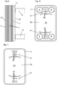
- Figs. 6-8 disclose a second embodiment which differs from the first embodiment in that it comprises two strengthening plates 2 instead of four strengthening plates 2. It is to be noted that in all embodiments, elements having substantially the same function are designated with the same reference signs.
- the strengthening plates 2 in the second embodiment are larger than in the first embodiment and extend over a zone including all four ports 8. Furthermore, in the second embodiment two of the inlet and outlet pipes 9 extend from one side of the plate heat exchanger and two of the inlet and outlet pipes 9 from the other opposite side of the plate heat exchanger.
- the strengthening plate 2, which is provided beside the frame plate 3, comprises four portholes which are concentric to a respective port 8.
- the strengthening plate 2, which is provided beside the pressure plate 4, see Fig. 8 is continuous, i.e. comprises no portholes.
- Figs. 9-11 disclose a third embodiment which differs from the first and second embodiments in that it comprises a strengthening plate 32 which also forms a frame plate on one side of the plate package and a strengthening 42 which also forms a pressure plate on the other opposite side of the plate package.
- the strengthening plates 32, 42 in the third embodiment are somewhat larger than in the second embodiment and comprises also a respective edge zone 11 forming a flange extending outwardly from the extension plane.
- the strengthening plates 32 comprise four portholes which are concentric to a respective port, whereas the strengthening plate 42, see Fig. 11 is continuous, i.e. comprises no portholes.
- one of the elongated depressions 22 of each strengthening pattern 21 has in the third embodiment received an alternative design with somewhat angled end sections.
Landscapes
- Engineering & Computer Science (AREA)
- Physics & Mathematics (AREA)
- Thermal Sciences (AREA)
- Mechanical Engineering (AREA)
- General Engineering & Computer Science (AREA)
- Heat-Exchange Devices With Radiators And Conduit Assemblies (AREA)
Claims (12)
- Plattenwärmeaustauscher, umfassend eine Mehrzahl von Platten, welche sich jeweils parallel zu einer Haupterstreckungsebene (p) erstrecken und welche eine Mehrzahl von Wärmetauscherplatten (1) und zumindest eine Verstärkungsplatte (2, 32, 42) umfassen,
wobei die Wärmetauscherplatten (1) nebeneinander angeordnet sind und ein Plattenpaket mit ersten Plattenzwischenräumen (5) für ein erstes Medium und zweiten Plattenzwischenräumen (6) für ein zweites Medium bilden,
wobei jede der Wärmetauscherplatten vier Bullaugen (7) aufweist, welche Öffnungen (8) bilden, welche sich durch das Plattenpaket erstrecken und Einlässe und Auslässe für das erste Medium zu den ersten Plattenzwischenräumen (5) und für das zweite Medium zu den zweiten Plattenzwischenräumen (6) bilden,
wobei die Wärmetauscherplatten (1) eine äußerste Wärmetauscherplatte (1') auf einer Seite des Plattenpakets und eine äußerste Wärmetauscherplatte (1") auf einer gegenüberliegenden Seite des Plattenpakets umfassen,
wobei zwei der Plattenzwischenräume (5, 6) im Plattenpaket einen jeweiligen äußersten Plattenzwischenraum auf einer jeweiligen Seite des Plattenpakets bilden, welche nach außen durch eine jeweilige der äußersten Wärmetauscherplatten (1', 1") begrenzt sind, und
wobei die Verstärkungsplatte (2, 32, 42) außerhalb einer der äußersten Wärmetauscherplatten (1', 1") bereitgestellt ist und einen Hauptbereich (20) aufweist, welcher sich parallel zur Erstreckungsebene (p) erstreckt,
dadurch gekennzeichnet, dass die Verstärkungsplatte (2, 32, 42) ein Verstärkungsmuster (21) umfasst, welches in der Nähe von zwei der Öffnungen (8) bereitgestellt ist und mehrere Vertiefungen (22) umfasst, welche sich nach außen vom Plattenpaket und den Wärmetauscherplatten (1) erstrecken, wobei die Vertiefungen (22) entlang der Erstreckungsebene (p) und, in einer senkrechten Richtung zur Erstreckungsebene (p) gesehen, langgestreckt sind, und wobei die Vertiefungen (22) eine im Wesentlichen gerade Erstreckung aufweisen und sich zwischen den zwei Öffnungen (8) erstrecken. - Plattenwärmeaustauscher nach Anspruch 1, dadurch gekennzeichnet, dass die Platten dauerhaft miteinander verbunden sind.
- Plattenwärmeaustauscher nach Anspruch 2, dadurch gekennzeichnet, dass die Platten dauerhaft miteinander durch Schmelzen eines metallischen Materials verbunden sind.
- Plattenwärmeaustauscher nach einem der vorhergehenden Ansprüche, dadurch gekennzeichnet, dass das Verstärkungsmuster (21) ausgebildet ist, um mit einem Druckmuster (13) der äußersten Wärmetauscherplatte (1', 1") zusammenzuwirken, welches neben der Verstärkungsplatte (2) so angeordnet ist, dass die Verstärkungsplatte (2) in einer definierten Position relativ zur äußersten Wärmetauscherplatte (1', 1") angeordnet ist.
- Plattenwärmeaustauscher nach einem der vorhergehenden Ansprüche, dadurch gekennzeichnet, dass der Hauptbereich (20) eine im Wesentlichen ebene Erstreckung aufweist, wobei das Verstärkungsmuster (21) sich nach außen von der Ebenenerstreckung erstreckt.
- Plattenwärmeaustauscher nach einem der vorhergehenden Ansprüche, dadurch gekennzeichnet, dass der Hauptbereich (20) eine Fläche aufweist, welche zumindest einen größeren Teil der Fläche der Verstärkungsplatte (2) bildet.
- Plattenwärmeaustauscher nach einem der vorhergehenden Ansprüche, dadurch gekennzeichnet, dass die Verstärkungsplatte (2, 32, 42) zumindest zwei Bullaugen umfasst, welche zu einer entsprechenden Öffnung (8) der zwei Öffnungen (8) konzentrisch sind.
- Plattenwärmeaustauscher nach einem der vorhergehenden Ansprüche, dadurch gekennzeichnet, dass die Verstärkungsplatte (2) zwei Verstärkungsmuster (21) umfasst, welche in der Nähe eines jeweiligen Paars von Öffnungen (8) angeordnet sind und welche jeweils mehrere Vertiefungen (22) aufweisen, welche sich nach außen von den Wärmetauscherplatten (1) erstrecken, wobei die Vertiefungen (22) entlang der Erstreckungsebene (p) und in einer senkrechten Richtung zur Erstreckungsebene (p) gesehen langgestreckt sind und wobei die Vertiefungen (22) eine im Wesentlichen gerade Erstreckung aufweisen und sich zwischen den Öffnungen (8) des jeweiligen Paars von Öffnungen erstrecken.
- Plattenwärmeaustauscher nach Anspruch 8, dadurch gekennzeichnet, dass die Verstärkungsplatte (2) zumindest vier Bullaugen umfasst, welche zu einer jeweiligen Öffnung (8) unter den Öffnungen (8) des Plattenpakets konzentrisch sind.
- Plattenwärmeaustauscher nach einem der vorhergehenden Ansprüche, dadurch gekennzeichnet, dass jede Wärmetauscherplatte (1) einen Wärmeaustauschbereich (10) und einen äußeren Randbereich (11) umfasst, welcher sich um den Wärmeaustauschbereich (10) erstreckt, wobei die Verstärkungsplatte (2) solche Abmessungen aufweist, dass sie innerhalb des äußeren Randbereichs (11) aufgenommen ist.
- Plattenwärmeaustauscher nach Anspruch 10, dadurch gekennzeichnet, dass der äußere Randbereich (11) einen umschließenden Flansch umfasst, welcher sich nach außen von der Erstreckungsebene (p) erstreckt.
- Plattenwärmeaustauscher nach einem der vorhergehenden Ansprüche, dadurch gekennzeichnet, dass die Platten eine weitere Verstärkungsplatte (2, 42) umfassen, welche außerhalb der zweiten der äußersten Wärmetauscherplatten (1") bereitgestellt ist, wobei die weitere Verstärkungsplatte (2, 42) einen Hauptbereich (20) aufweist, welcher sich parallel zur Erstreckungsebene (p) erstreckt und ein Verstärkungsmuster (21) umfasst, welches in der Nähe von zwei der Öffnungen (8) angeordnet ist und zumindest eine Vertiefung (22) umfasst, welche sich nach außen von den Wärmetauscherplatten (1) erstreckt.
Priority Applications (1)
| Application Number | Priority Date | Filing Date | Title |
|---|---|---|---|
| SI200731979T SI2002195T1 (sl) | 2006-04-04 | 2007-03-29 | Ploščni toplotni izmenjevalnik, ki vključuje ojačitvene plošče, predvidene zunaj najbolj oddaljenih plošč toplotnega izmenjevalnika |
Applications Claiming Priority (2)
| Application Number | Priority Date | Filing Date | Title |
|---|---|---|---|
| SE0600758A SE529769E (sv) | 2006-04-04 | 2006-04-04 | Plattvärmeväxlare vilken innefattar åtminstone en förstärkningsplatta vilken är anordnad utanför en av de yttre värmeväxlarplattorna |
| PCT/SE2007/050198 WO2007114779A1 (en) | 2006-04-04 | 2007-03-29 | Plate heat exchanger including strengthening plates provided outside of the outermost heat exhanger plates |
Publications (3)
| Publication Number | Publication Date |
|---|---|
| EP2002195A1 EP2002195A1 (de) | 2008-12-17 |
| EP2002195A4 EP2002195A4 (de) | 2013-09-11 |
| EP2002195B1 true EP2002195B1 (de) | 2017-10-18 |
Family
ID=38563956
Family Applications (1)
| Application Number | Title | Priority Date | Filing Date |
|---|---|---|---|
| EP07748359.2A Not-in-force EP2002195B1 (de) | 2006-04-04 | 2007-03-29 | Plattenwärmeaustauscher mit verstärkungsplatten ausserhalb der äussersten wärmetauscherplatten |
Country Status (11)
| Country | Link |
|---|---|
| US (1) | US8181696B2 (de) |
| EP (1) | EP2002195B1 (de) |
| JP (1) | JP5043930B2 (de) |
| CN (1) | CN101416017B (de) |
| BR (1) | BRPI0708132B1 (de) |
| DK (1) | DK2002195T3 (de) |
| ES (1) | ES2648219T3 (de) |
| RU (1) | RU2419053C2 (de) |
| SE (1) | SE529769E (de) |
| SI (1) | SI2002195T1 (de) |
| WO (1) | WO2007114779A1 (de) |
Families Citing this family (14)
| Publication number | Priority date | Publication date | Assignee | Title |
|---|---|---|---|---|
| SE532489C2 (sv) * | 2007-02-26 | 2010-02-02 | Alfa Laval Corp Ab | Plattvärmeväxlare |
| FR2985012B1 (fr) * | 2011-12-22 | 2015-05-08 | Valeo Sys Controle Moteur Sas | Echangeur de chaleur a plaques empilees comprenant un collecteur. |
| SE537142C2 (sv) * | 2012-02-14 | 2015-02-17 | Alfa Laval Corp Ab | Plattvärmeväxlare med förbättrad hållfasthet i portområdet |
| US20140196870A1 (en) * | 2013-01-17 | 2014-07-17 | Hamilton Sundstrand Corporation | Plate heat exchanger |
| CN103148735A (zh) * | 2013-03-05 | 2013-06-12 | 浙江鸿远制冷设备有限公司 | 一种钎焊板式换热器 |
| WO2015040065A1 (en) * | 2013-09-17 | 2015-03-26 | Swep International Ab | A plate heat exchanger having reinforcing means |
| SI2886994T1 (sl) | 2013-12-20 | 2016-10-28 | Alfa Laval Corporate Ab | Ploščni izmenjevalnik toplote z montirno prirobnico |
| JP6626086B2 (ja) * | 2014-04-04 | 2019-12-25 | チタンエックス ホールディング アクチエボラグTitanX Holding AB | 熱交換器および熱交換器の製造方法 |
| EP3182048A1 (de) * | 2015-12-16 | 2017-06-21 | Alfa Laval Corporate AB | Lukendichtung, anordnung für einen wärmetauscher und wärmetauscher mit solch einer anordnung |
| US10876794B2 (en) * | 2017-06-12 | 2020-12-29 | Ingersoll-Rand Industrial U.S., Inc. | Gasketed plate and shell heat exchanger |
| DE112018006972T5 (de) * | 2018-01-29 | 2020-10-08 | Dana Canada Corporation | Baulich unterstützter wärmetauscher |
| SE544093C2 (en) * | 2019-05-21 | 2021-12-21 | Alfa Laval Corp Ab | Plate heat exchanger, and a method of manufacturing a plate heat exchanger |
| CN112146483A (zh) * | 2019-06-28 | 2020-12-29 | 浙江三花智能控制股份有限公司 | 板式换热器 |
| EP4603780A1 (de) * | 2024-02-15 | 2025-08-20 | Alfa Laval Corporate AB | Verfahren zur herstellung einer verstärkten wärmeübertragungsplatte mittels generativer fertigung |
Family Cites Families (25)
| Publication number | Priority date | Publication date | Assignee | Title |
|---|---|---|---|---|
| FR2224727B1 (de) * | 1973-04-04 | 1975-08-22 | Chausson Usines Sa | |
| JPS5937986U (ja) * | 1982-08-31 | 1984-03-10 | 株式会社土屋製作所 | 熱交換器用プレ−トフインチユ−ブ |
| JPH0141033Y2 (de) * | 1985-02-28 | 1989-12-06 | ||
| SE458884B (sv) | 1987-05-29 | 1989-05-16 | Alfa Laval Thermal Ab | Permanent sammanfogad plattvaermevaexlare med sammanhaallande organ vid portarna |
| US4872578A (en) * | 1988-06-20 | 1989-10-10 | Itt Standard Of Itt Corporation | Plate type heat exchanger |
| SU1636680A1 (ru) | 1988-12-06 | 1991-03-23 | Предприятие П/Я А-1496 | Пластинчатый теплообменник |
| SE9000712L (sv) * | 1990-02-28 | 1991-08-29 | Alfa Laval Thermal | Permanent sammanfogad plattvaermevaexlare |
| SE467275B (sv) * | 1990-05-02 | 1992-06-22 | Alfa Laval Thermal Ab | Loedd dubbelvaeggig plattvaermevaexlare med bockade kanter |
| JPH0614777U (ja) * | 1992-07-27 | 1994-02-25 | 株式会社アタゴ製作所 | プレート式熱交換器 |
| JPH06257983A (ja) * | 1993-03-09 | 1994-09-16 | Nissan Motor Co Ltd | 積層型熱交換器 |
| DE4313506A1 (de) | 1993-04-24 | 1994-10-27 | Knecht Filterwerke Gmbh | Ölkühler in Scheibenbauweise |
| KR950704665A (ko) * | 1993-09-16 | 1995-11-20 | 이시마루 쓰네오 | 알루미늄제 열교환기(aluminum heat exchanger) |
| FR2720490B1 (fr) * | 1994-05-26 | 1996-07-12 | Valeo Thermique Moteur Sa | Plaque collectrice renforcée pour échangeur de chaleur. |
| JP2887442B2 (ja) * | 1994-09-22 | 1999-04-26 | 株式会社ゼクセル | 積層型熱交換器 |
| FR2735855B1 (fr) * | 1995-06-23 | 1997-08-01 | Valeo Climatisation | Procede d'assemblage d'un sous-ensemble d'echangeur de chaleur |
| SE504868C2 (sv) * | 1995-10-23 | 1997-05-20 | Swep International Ab | Plattvärmeväxlare med ändplatta med pressat mönster |
| JPH09273886A (ja) | 1996-04-04 | 1997-10-21 | Tokyo Radiator Seizo Kk | 積層型熱交換器 |
| US5964280A (en) | 1996-07-16 | 1999-10-12 | Modine Manufacturing Company | Multiple fluid path plate heat exchanger |
| JP3812021B2 (ja) * | 1996-12-03 | 2006-08-23 | 株式会社デンソー | 積層型熱交換器 |
| SE515467C2 (sv) * | 1999-12-23 | 2001-08-13 | Alfa Laval Ab | Plattvärmeväxlare med minst en platta försedd med ett trågformat parti för bildande av ett avtätat utrymme. |
| DE20010816U1 (de) * | 2000-06-17 | 2001-11-15 | Behr Gmbh & Co, 70469 Stuttgart | Stapelscheiben-Wärmeübertrager |
| JP2002286394A (ja) * | 2001-03-23 | 2002-10-03 | Denso Corp | 熱交換器 |
| DE10158387B4 (de) * | 2001-11-28 | 2017-01-19 | Modine Manufacturing Co. | Anordnung zur Kühlung von elektrischen Komponenten |
| FR2846733B1 (fr) * | 2002-10-31 | 2006-09-15 | Valeo Thermique Moteur Sa | Condenseur, notamment pour un circuit de cimatisation de vehicule automobile, et circuit comprenant ce condenseur |
| JP2005055074A (ja) * | 2003-08-04 | 2005-03-03 | Calsonic Kansei Corp | 熱交換器 |
-
2006
- 2006-04-04 SE SE0600758A patent/SE529769E/sv unknown
-
2007
- 2007-03-29 WO PCT/SE2007/050198 patent/WO2007114779A1/en not_active Ceased
- 2007-03-29 ES ES07748359.2T patent/ES2648219T3/es active Active
- 2007-03-29 SI SI200731979T patent/SI2002195T1/sl unknown
- 2007-03-29 RU RU2008143407/06A patent/RU2419053C2/ru not_active IP Right Cessation
- 2007-03-29 JP JP2009504158A patent/JP5043930B2/ja not_active Expired - Fee Related
- 2007-03-29 CN CN200780011930.5A patent/CN101416017B/zh not_active Expired - Fee Related
- 2007-03-29 BR BRPI0708132A patent/BRPI0708132B1/pt not_active IP Right Cessation
- 2007-03-29 US US12/281,505 patent/US8181696B2/en not_active Expired - Fee Related
- 2007-03-29 DK DK07748359.2T patent/DK2002195T3/en active
- 2007-03-29 EP EP07748359.2A patent/EP2002195B1/de not_active Not-in-force
Non-Patent Citations (1)
| Title |
|---|
| None * |
Also Published As
| Publication number | Publication date |
|---|---|
| BRPI0708132B1 (pt) | 2018-11-21 |
| SE0600758L (sv) | 2007-10-05 |
| DK2002195T3 (en) | 2018-01-08 |
| US20090008072A1 (en) | 2009-01-08 |
| CN101416017A (zh) | 2009-04-22 |
| RU2008143407A (ru) | 2010-05-10 |
| SE529769E (sv) | 2014-04-22 |
| EP2002195A4 (de) | 2013-09-11 |
| BRPI0708132A8 (pt) | 2018-05-08 |
| JP5043930B2 (ja) | 2012-10-10 |
| CN101416017B (zh) | 2010-11-10 |
| RU2419053C2 (ru) | 2011-05-20 |
| SI2002195T1 (sl) | 2017-12-29 |
| BRPI0708132A2 (pt) | 2011-05-17 |
| JP2009532660A (ja) | 2009-09-10 |
| SE529769C2 (sv) | 2007-11-20 |
| WO2007114779A1 (en) | 2007-10-11 |
| US8181696B2 (en) | 2012-05-22 |
| ES2648219T3 (es) | 2017-12-29 |
| EP2002195A1 (de) | 2008-12-17 |
Similar Documents
| Publication | Publication Date | Title |
|---|---|---|
| EP2002195B1 (de) | Plattenwärmeaustauscher mit verstärkungsplatten ausserhalb der äussersten wärmetauscherplatten | |
| EP2585783B1 (de) | Wärmetauscherplatte und wärmetauscher | |
| EP2361365B1 (de) | Platte und dichtung für einen plattenwärmetauscher | |
| EP2394129B1 (de) | Plattenwärmetauscher | |
| CA2228011C (en) | Heat exchanger | |
| EP1702193B1 (de) | Plattenwärmetauscher | |
| CA2269058C (en) | Heat exchanger | |
| CA2861234C (en) | Plate heat exchanger with improved strength in port area | |
| EP1593923B1 (de) | Wärmetauscher | |
| EP3742100B1 (de) | Plattenwärmetauscher | |
| EP2064507B1 (de) | Plattenwärmetauscher | |
| US12529522B2 (en) | Heat exchanger construction | |
| CA2512318A1 (en) | Heat exchangers with corrugated heat exchange elements of improved strength | |
| EP1712864A1 (de) | Verfahren zur Herstellung eines Wärmetauschers und Abstandshalters |
Legal Events
| Date | Code | Title | Description |
|---|---|---|---|
| PUAI | Public reference made under article 153(3) epc to a published international application that has entered the european phase |
Free format text: ORIGINAL CODE: 0009012 |
|
| 17P | Request for examination filed |
Effective date: 20080722 |
|
| AK | Designated contracting states |
Kind code of ref document: A1 Designated state(s): AT BE BG CH CY CZ DE DK EE ES FI FR GB GR HU IE IS IT LI LT LU LV MC MT NL PL PT RO SE SI SK TR |
|
| DAX | Request for extension of the european patent (deleted) | ||
| A4 | Supplementary search report drawn up and despatched |
Effective date: 20130809 |
|
| RIC1 | Information provided on ipc code assigned before grant |
Ipc: F28F 3/08 20060101ALI20130805BHEP Ipc: F28D 9/00 20060101ALI20130805BHEP Ipc: F28F 9/02 20060101AFI20130805BHEP |
|
| STAA | Information on the status of an ep patent application or granted ep patent |
Free format text: STATUS: EXAMINATION IS IN PROGRESS |
|
| 17Q | First examination report despatched |
Effective date: 20170206 |
|
| GRAP | Despatch of communication of intention to grant a patent |
Free format text: ORIGINAL CODE: EPIDOSNIGR1 |
|
| STAA | Information on the status of an ep patent application or granted ep patent |
Free format text: STATUS: GRANT OF PATENT IS INTENDED |
|
| INTG | Intention to grant announced |
Effective date: 20170526 |
|
| GRAS | Grant fee paid |
Free format text: ORIGINAL CODE: EPIDOSNIGR3 |
|
| GRAA | (expected) grant |
Free format text: ORIGINAL CODE: 0009210 |
|
| STAA | Information on the status of an ep patent application or granted ep patent |
Free format text: STATUS: THE PATENT HAS BEEN GRANTED |
|
| AK | Designated contracting states |
Kind code of ref document: B1 Designated state(s): AT BE BG CH CY CZ DE DK EE ES FI FR GB GR HU IE IS IT LI LT LU LV MC MT NL PL PT RO SE SI SK TR |
|
| REG | Reference to a national code |
Ref country code: GB Ref legal event code: FG4D |
|
| REG | Reference to a national code |
Ref country code: CH Ref legal event code: EP |
|
| REG | Reference to a national code |
Ref country code: SE Ref legal event code: TRGR |
|
| REG | Reference to a national code |
Ref country code: AT Ref legal event code: REF Ref document number: 938341 Country of ref document: AT Kind code of ref document: T Effective date: 20171115 Ref country code: IE Ref legal event code: FG4D |
|
| REG | Reference to a national code |
Ref country code: DE Ref legal event code: R096 Ref document number: 602007052731 Country of ref document: DE |
|
| REG | Reference to a national code |
Ref country code: ES Ref legal event code: FG2A Ref document number: 2648219 Country of ref document: ES Kind code of ref document: T3 Effective date: 20171229 |
|
| REG | Reference to a national code |
Ref country code: DK Ref legal event code: T3 Effective date: 20180104 |
|
| REG | Reference to a national code |
Ref country code: NL Ref legal event code: MP Effective date: 20171018 |
|
| REG | Reference to a national code |
Ref country code: FR Ref legal event code: PLFP Year of fee payment: 12 |
|
| REG | Reference to a national code |
Ref country code: LT Ref legal event code: MG4D |
|
| REG | Reference to a national code |
Ref country code: AT Ref legal event code: MK05 Ref document number: 938341 Country of ref document: AT Kind code of ref document: T Effective date: 20171018 |
|
| PG25 | Lapsed in a contracting state [announced via postgrant information from national office to epo] |
Ref country code: NL Free format text: LAPSE BECAUSE OF FAILURE TO SUBMIT A TRANSLATION OF THE DESCRIPTION OR TO PAY THE FEE WITHIN THE PRESCRIBED TIME-LIMIT Effective date: 20171018 |
|
| PG25 | Lapsed in a contracting state [announced via postgrant information from national office to epo] |
Ref country code: LT Free format text: LAPSE BECAUSE OF FAILURE TO SUBMIT A TRANSLATION OF THE DESCRIPTION OR TO PAY THE FEE WITHIN THE PRESCRIBED TIME-LIMIT Effective date: 20171018 Ref country code: FI Free format text: LAPSE BECAUSE OF FAILURE TO SUBMIT A TRANSLATION OF THE DESCRIPTION OR TO PAY THE FEE WITHIN THE PRESCRIBED TIME-LIMIT Effective date: 20171018 |
|
| PG25 | Lapsed in a contracting state [announced via postgrant information from national office to epo] |
Ref country code: LV Free format text: LAPSE BECAUSE OF FAILURE TO SUBMIT A TRANSLATION OF THE DESCRIPTION OR TO PAY THE FEE WITHIN THE PRESCRIBED TIME-LIMIT Effective date: 20171018 Ref country code: GR Free format text: LAPSE BECAUSE OF FAILURE TO SUBMIT A TRANSLATION OF THE DESCRIPTION OR TO PAY THE FEE WITHIN THE PRESCRIBED TIME-LIMIT Effective date: 20180119 Ref country code: AT Free format text: LAPSE BECAUSE OF FAILURE TO SUBMIT A TRANSLATION OF THE DESCRIPTION OR TO PAY THE FEE WITHIN THE PRESCRIBED TIME-LIMIT Effective date: 20171018 Ref country code: BG Free format text: LAPSE BECAUSE OF FAILURE TO SUBMIT A TRANSLATION OF THE DESCRIPTION OR TO PAY THE FEE WITHIN THE PRESCRIBED TIME-LIMIT Effective date: 20180118 Ref country code: IS Free format text: LAPSE BECAUSE OF FAILURE TO SUBMIT A TRANSLATION OF THE DESCRIPTION OR TO PAY THE FEE WITHIN THE PRESCRIBED TIME-LIMIT Effective date: 20180218 |
|
| REG | Reference to a national code |
Ref country code: DE Ref legal event code: R097 Ref document number: 602007052731 Country of ref document: DE |
|
| PG25 | Lapsed in a contracting state [announced via postgrant information from national office to epo] |
Ref country code: EE Free format text: LAPSE BECAUSE OF FAILURE TO SUBMIT A TRANSLATION OF THE DESCRIPTION OR TO PAY THE FEE WITHIN THE PRESCRIBED TIME-LIMIT Effective date: 20171018 Ref country code: CZ Free format text: LAPSE BECAUSE OF FAILURE TO SUBMIT A TRANSLATION OF THE DESCRIPTION OR TO PAY THE FEE WITHIN THE PRESCRIBED TIME-LIMIT Effective date: 20171018 |
|
| PLBE | No opposition filed within time limit |
Free format text: ORIGINAL CODE: 0009261 |
|
| STAA | Information on the status of an ep patent application or granted ep patent |
Free format text: STATUS: NO OPPOSITION FILED WITHIN TIME LIMIT |
|
| PG25 | Lapsed in a contracting state [announced via postgrant information from national office to epo] |
Ref country code: PL Free format text: LAPSE BECAUSE OF FAILURE TO SUBMIT A TRANSLATION OF THE DESCRIPTION OR TO PAY THE FEE WITHIN THE PRESCRIBED TIME-LIMIT Effective date: 20171018 Ref country code: RO Free format text: LAPSE BECAUSE OF FAILURE TO SUBMIT A TRANSLATION OF THE DESCRIPTION OR TO PAY THE FEE WITHIN THE PRESCRIBED TIME-LIMIT Effective date: 20171018 |
|
| 26N | No opposition filed |
Effective date: 20180719 |
|
| REG | Reference to a national code |
Ref country code: CH Ref legal event code: PL |
|
| PG25 | Lapsed in a contracting state [announced via postgrant information from national office to epo] |
Ref country code: MC Free format text: LAPSE BECAUSE OF FAILURE TO SUBMIT A TRANSLATION OF THE DESCRIPTION OR TO PAY THE FEE WITHIN THE PRESCRIBED TIME-LIMIT Effective date: 20171018 |
|
| REG | Reference to a national code |
Ref country code: BE Ref legal event code: MM Effective date: 20180331 |
|
| REG | Reference to a national code |
Ref country code: IE Ref legal event code: MM4A |
|
| PG25 | Lapsed in a contracting state [announced via postgrant information from national office to epo] |
Ref country code: LU Free format text: LAPSE BECAUSE OF NON-PAYMENT OF DUE FEES Effective date: 20180329 |
|
| PG25 | Lapsed in a contracting state [announced via postgrant information from national office to epo] |
Ref country code: IE Free format text: LAPSE BECAUSE OF NON-PAYMENT OF DUE FEES Effective date: 20180329 |
|
| PG25 | Lapsed in a contracting state [announced via postgrant information from national office to epo] |
Ref country code: BE Free format text: LAPSE BECAUSE OF NON-PAYMENT OF DUE FEES Effective date: 20180331 Ref country code: CH Free format text: LAPSE BECAUSE OF NON-PAYMENT OF DUE FEES Effective date: 20180331 Ref country code: LI Free format text: LAPSE BECAUSE OF NON-PAYMENT OF DUE FEES Effective date: 20180331 |
|
| PGFP | Annual fee paid to national office [announced via postgrant information from national office to epo] |
Ref country code: IT Payment date: 20190326 Year of fee payment: 13 Ref country code: DE Payment date: 20190319 Year of fee payment: 13 Ref country code: GB Payment date: 20190327 Year of fee payment: 13 |
|
| PGFP | Annual fee paid to national office [announced via postgrant information from national office to epo] |
Ref country code: SE Payment date: 20190311 Year of fee payment: 13 Ref country code: SI Payment date: 20190215 Year of fee payment: 13 Ref country code: DK Payment date: 20190312 Year of fee payment: 13 Ref country code: FR Payment date: 20190213 Year of fee payment: 13 |
|
| PGFP | Annual fee paid to national office [announced via postgrant information from national office to epo] |
Ref country code: SK Payment date: 20190227 Year of fee payment: 13 |
|
| PGFP | Annual fee paid to national office [announced via postgrant information from national office to epo] |
Ref country code: ES Payment date: 20190401 Year of fee payment: 13 |
|
| PG25 | Lapsed in a contracting state [announced via postgrant information from national office to epo] |
Ref country code: MT Free format text: LAPSE BECAUSE OF NON-PAYMENT OF DUE FEES Effective date: 20180329 |
|
| PG25 | Lapsed in a contracting state [announced via postgrant information from national office to epo] |
Ref country code: TR Free format text: LAPSE BECAUSE OF FAILURE TO SUBMIT A TRANSLATION OF THE DESCRIPTION OR TO PAY THE FEE WITHIN THE PRESCRIBED TIME-LIMIT Effective date: 20171018 |
|
| PG25 | Lapsed in a contracting state [announced via postgrant information from national office to epo] |
Ref country code: HU Free format text: LAPSE BECAUSE OF FAILURE TO SUBMIT A TRANSLATION OF THE DESCRIPTION OR TO PAY THE FEE WITHIN THE PRESCRIBED TIME-LIMIT; INVALID AB INITIO Effective date: 20070329 Ref country code: PT Free format text: LAPSE BECAUSE OF FAILURE TO SUBMIT A TRANSLATION OF THE DESCRIPTION OR TO PAY THE FEE WITHIN THE PRESCRIBED TIME-LIMIT Effective date: 20171018 |
|
| PG25 | Lapsed in a contracting state [announced via postgrant information from national office to epo] |
Ref country code: CY Free format text: LAPSE BECAUSE OF FAILURE TO SUBMIT A TRANSLATION OF THE DESCRIPTION OR TO PAY THE FEE WITHIN THE PRESCRIBED TIME-LIMIT Effective date: 20171018 |
|
| REG | Reference to a national code |
Ref country code: DE Ref legal event code: R119 Ref document number: 602007052731 Country of ref document: DE |
|
| REG | Reference to a national code |
Ref country code: DK Ref legal event code: EBP Effective date: 20200331 |
|
| REG | Reference to a national code |
Ref country code: SK Ref legal event code: MM4A Ref document number: E 25815 Country of ref document: SK Effective date: 20200329 |
|
| PG25 | Lapsed in a contracting state [announced via postgrant information from national office to epo] |
Ref country code: DE Free format text: LAPSE BECAUSE OF NON-PAYMENT OF DUE FEES Effective date: 20201001 Ref country code: FR Free format text: LAPSE BECAUSE OF NON-PAYMENT OF DUE FEES Effective date: 20200331 Ref country code: SE Free format text: LAPSE BECAUSE OF NON-PAYMENT OF DUE FEES Effective date: 20200330 |
|
| PG25 | Lapsed in a contracting state [announced via postgrant information from national office to epo] |
Ref country code: SK Free format text: LAPSE BECAUSE OF NON-PAYMENT OF DUE FEES Effective date: 20200329 |
|
| GBPC | Gb: european patent ceased through non-payment of renewal fee |
Effective date: 20200329 |
|
| PG25 | Lapsed in a contracting state [announced via postgrant information from national office to epo] |
Ref country code: DK Free format text: LAPSE BECAUSE OF NON-PAYMENT OF DUE FEES Effective date: 20200331 Ref country code: GB Free format text: LAPSE BECAUSE OF NON-PAYMENT OF DUE FEES Effective date: 20200329 |
|
| PG25 | Lapsed in a contracting state [announced via postgrant information from national office to epo] |
Ref country code: SI Free format text: LAPSE BECAUSE OF NON-PAYMENT OF DUE FEES Effective date: 20200330 |
|
| REG | Reference to a national code |
Ref country code: ES Ref legal event code: FD2A Effective date: 20210812 |
|
| PG25 | Lapsed in a contracting state [announced via postgrant information from national office to epo] |
Ref country code: IT Free format text: LAPSE BECAUSE OF NON-PAYMENT OF DUE FEES Effective date: 20200329 |
|
| PG25 | Lapsed in a contracting state [announced via postgrant information from national office to epo] |
Ref country code: ES Free format text: LAPSE BECAUSE OF NON-PAYMENT OF DUE FEES Effective date: 20200330 |