EP1700977B1 - Locking device for frames of scaffolds and strutting towers - Google Patents
Locking device for frames of scaffolds and strutting towers Download PDFInfo
- Publication number
- EP1700977B1 EP1700977B1 EP06358004.7A EP06358004A EP1700977B1 EP 1700977 B1 EP1700977 B1 EP 1700977B1 EP 06358004 A EP06358004 A EP 06358004A EP 1700977 B1 EP1700977 B1 EP 1700977B1
- Authority
- EP
- European Patent Office
- Prior art keywords
- frames
- balustrades
- balustrade
- locking
- orifices
- Prior art date
- Legal status (The legal status is an assumption and is not a legal conclusion. Google has not performed a legal analysis and makes no representation as to the accuracy of the status listed.)
- Not-in-force
Links
Images


Classifications
-
- E—FIXED CONSTRUCTIONS
- E04—BUILDING
- E04G—SCAFFOLDING; FORMS; SHUTTERING; BUILDING IMPLEMENTS OR AIDS, OR THEIR USE; HANDLING BUILDING MATERIALS ON THE SITE; REPAIRING, BREAKING-UP OR OTHER WORK ON EXISTING BUILDINGS
- E04G7/00—Connections between parts of the scaffold
- E04G7/02—Connections between parts of the scaffold with separate coupling elements
- E04G7/06—Stiff scaffolding clamps for connecting scaffold members of common shape
- E04G7/20—Stiff scaffolding clamps for connecting scaffold members of common shape for ends of members only, e.g. for connecting members in end-to-end relation
-
- E—FIXED CONSTRUCTIONS
- E04—BUILDING
- E04G—SCAFFOLDING; FORMS; SHUTTERING; BUILDING IMPLEMENTS OR AIDS, OR THEIR USE; HANDLING BUILDING MATERIALS ON THE SITE; REPAIRING, BREAKING-UP OR OTHER WORK ON EXISTING BUILDINGS
- E04G5/00—Component parts or accessories for scaffolds
- E04G5/14—Railings
-
- E—FIXED CONSTRUCTIONS
- E04—BUILDING
- E04G—SCAFFOLDING; FORMS; SHUTTERING; BUILDING IMPLEMENTS OR AIDS, OR THEIR USE; HANDLING BUILDING MATERIALS ON THE SITE; REPAIRING, BREAKING-UP OR OTHER WORK ON EXISTING BUILDINGS
- E04G7/00—Connections between parts of the scaffold
- E04G7/30—Scaffolding bars or members with non-detachably fixed coupling elements
- E04G7/301—Scaffolding bars or members with non-detachably fixed coupling elements for connecting bars or members which are parallel or in end-to-end relation
Definitions
- the present invention relates to a locking device of the safety pin type for the construction of shoring towers and other scaffolds.
- the technical field of the invention is that of the design of shoring materials, scaffolding and security for building and special works.
- the locking device of the invention applies in particular to the construction of shoring towers type "tour ladder” whose vertical payload per amount can go up to 6 tons.
- Such towers are traditionally composed of support elements such as jacks or base plates providing a stable planar support on the ground and possibly interconnected in pairs by horizontal diagonals spacing the feet of the tower.
- first frames comprising amounts interconnected by cross members forming ladder bars, the amounts of each frame fitting on a support member and being locked thereon by a pin.
- Railings are then installed between the upper ends of the uprights of the frames, said railings comprising smooth connectors having at their ends means of connection to said uprights allowing on the one hand the interlocking of the railings on the first level of frames and secondly the establishment of a second level of frames above the first level, the railings are thus "pinched" between two successive frames, the link between these two levels of frames being secured with locking pins inserted into holes pierced right through the upper and lower ends of the frame uprights.
- the locking pins currently used for the construction of shoring and scaffolding towers have a straight pin for insertion into the holes in the posts of the tower or scaffold frames, and a tab formed or attached in the frame. extension of said pin and forming an angle relative thereto, said tab being shaped and oriented (or orientable) relative to the pin so as to allow locking of the pin in the holes of the amounts of the frames.
- Specific examples of such pins are described in the patent FR 1 082 293 and in the German utility model DE 9215110 U1 which discloses all the features of the preamble of claim 1.
- the present invention aims to provide a new type of locking for such shoring towers and scaffolding that overcomes the disadvantages of existing pins.
- a device for locking construction elements of shoring towers or scaffolds comprising at least two pins forming a "U" capable of being inserted through holes pierced transversely from one side to the assembly ends of said construction elements.
- Said building elements nest or juxtapose to form a said tower or scaffold so that said orifices at their ends are aligned to allow the passage of said pins of the device.
- the device according to the invention is as defined in claim 1.
- the device according to the invention comprises a non-return latch, said latch having a determined length allowing its tilting from a raised position of disengagement of the device to a tilted position of locking as and when the insertion of said pins in said orifices of said elements to be locked, said locking position being reached when said pins are fully inserted into said orifices of said elements, the length of said latch being such that the free end of said latch abuts against at least a fixed part of said 'a said railing after tipping.
- the device of the invention comprises a connection and sliding means integral with one end of said pins and for fixing said device on the rail of a said guardrail.
- the locking device of the invention is particularly advantageous in that it makes it possible to prevent slipping and falling of the pin of the device out of the locking holes of the frames, even when case of vibrations of the tower or blows on the device.
- the latch anti-return whose shape and length are adapted depending on the guardrail models, abuts the reservation of the railing installed between two successive frames nested one in the other, thus preventing the recoil of the pin and the locking device as a whole.
- To then remove the device simply raise the latch manually and remove the pin out of the holes to release the frames and the guard.
- said connecting means advantageously avoids the loss of the locking device, while allowing easy and quick placement thereof on the rail of a guardrail.
- said latch In its said locking position, said latch abuts against a protruding portion of the construction element on which the device is optionally fixed by means of its said connection and sliding means, which can be reversible connection means.
- the device according to the invention has the advantage of allowing the locking of two successive frames on a guard rail on either side of the end of the rail thereof.
- This is particularly advantageous when it is the guardrail which, at the ends of its smooth, comprises connector sleeves on which fit the upper and lower ends respectively of two successive frames of a ladder tower. It is thus possible to move the set of the tower by cranage without risk of dismemberment of the tower by separation of its elements.
- the locking device of the invention can advantageously be installed on the rail of a railing, said device sliding in a limited manner between the fastening means of said railing at the ends of said rail and the guard's bookings. body, as defined in claim 5.
- a guardrail comprising a locking device according to the invention integral and sliding at each end of its rail by means of said connecting and sliding means, in order to allow inserting at least two of said pins of said locking device into said holes of said two successive frame members to be locked with said shoring tower or scaffold, said latch of the locking device engaging with abutment against said reservation of said guard when it is tilted in its said locking position.
- said means for connecting and sliding the device is a reversible connection means which will thus remove if necessary the locking device of the railing rail.
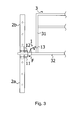
- the locking device 1 With reference first to Figures 1A, 1B , the locking device 1 according to the invention, named in the following description "locking pin”, comprises two pins 11, 12 parallel and connected to one another by a cord conferring on the pin 1 a shape "U".
- the cord connecting said pins 11, 12 is welded to the outer surface of a tubular parallelepipedal section 14 constituting a connecting ring for threading the pin 1 on a complementary shape guide such as a railing rail as represented at Figures 2 to 4 .
- the ring 14 can be made by two halves of tube connected to each other by a hinge along one of their longitudinal edge, thus constituting a reversible connection and sliding means of the pin 1, said ring 14 can be kept closed after installation of the pin by any suitable means such as collars, bolts or other.
- the locking device of the invention is particularly suitable for securing assemblies of shoring tower and scaffolding elements such as frames and guardrails.
- the pin 1 of the invention may in particular be slidably mounted via its ring 14 on the rail 32 of a railing 3 between the end connectors 33 of said rail 32 and the reservation 31 of said guard body.
- Said connectors 33 comprise orifices 8 pierced right through in the axis of the pins 11, 12 of the pin when it is mounted on the rail 32 of the railing 3, said pins being thus insertable into said orifices 8 by sliding the pin 1 to the connectors 33.
- the latch 13 is in a raised position of release of the pin, are free end bearing against the reservation 31 guardrail 3 and the elastic return means 5 of the latch being in tension.
- Said uprights of the frames 2a, 2b also have at their upper and lower ends respectively orifices 7 pierced right through so that they correspond exactly in alignment with the orifices 8 pierced in the connectors 33 of the guardrail.
- the sliding of the pin causes a sliding and tilting of the latch 13 of the pin against the reservation 31 of the railing under the effect of the weight of the latch 13.
- This tilting of the latch 13 of the pin continues until it reaches its locking position when the pins 11, 12 are fully inserted into the openings 7, 8 of the frames 2a, 2b and the railing connectors 33 ( figure 4 ).
- the free end of said latch 13 engages against the connection of the reservation 31 of the railing 3 on the rail 32, thus preventing the retraction of the pin 1 and the withdrawal of the pins 11, 12 of the latter out of orifices 7, 8.
- the length of the latch 13 will be determined according to the distance between the reservation 31 of the guard rail 3 connectors 33 at the ends of the rail 32 and the length of the ring 14 on which is fixed the latch 13.
- the locking pin according to the invention allows an automatic locking of the pins 11, 12 in the openings of the frames 2a, 2b to lock, the particular folded shape of the latch 13 and the return means 5 thereof ensuring the maintaining said latch in the locked position, even in case of blows on the ends of the pins 11, 12 or vibrations.
- the pin 1 being fixed by its ring 14 on the rail 32 of the railing 3, it is completely captive, even in case of regular assembly and disassembly of said railing and / or transport thereof.
- the locking pin 1 of the invention being captive, it further allows when the latch 13 and in its locking position abuts against the reservation 31 of the railing to transport the shoring towers and scaffolds whose elements are locked. using cranes without risk of dismemberment of the elements constituting said tower or said scaffolding.
Description
La présente invention concerne un dispositif de verrouillage de type goupille de sécurité pour la construction de tours d'étaiements et autres échafaudages.The present invention relates to a locking device of the safety pin type for the construction of shoring towers and other scaffolds.
Le domaine technique de l'invention est celui de la conception de matériels d'étaiement, d'échafaudage et de sécurité pour le bâtiment et les travaux spéciaux.The technical field of the invention is that of the design of shoring materials, scaffolding and security for building and special works.
Le dispositif de verrouillage de l'invention s'applique en particulier aux constructions de tours d'étaiement de type "tour échelle" dont la charge utile verticale par montant peut aller jusqu'à 6 tonnes. De telles tours sont traditionnellement composées d'éléments d'appui tels que des vérins ou des plaques de base fournissant un appui plan stable sur le sol et éventuellement reliés entre eux deux à deux par des diagonales horizontales d'écartement des pieds de la tour.The locking device of the invention applies in particular to the construction of shoring towers type "tour ladder" whose vertical payload per amount can go up to 6 tons. Such towers are traditionally composed of support elements such as jacks or base plates providing a stable planar support on the ground and possibly interconnected in pairs by horizontal diagonals spacing the feet of the tower.
Sur ces éléments d'appuis sont ensuite installés parallèlement des premiers cadres comprenant des montants reliés entre eux par des traverses formant des barreaux d'échelle, les montants de chaque cadre s'emboîtant sur un élément d'appui et étant verrouillé sur celui-ci par une goupille. Une fois les cadres sécurisés aux éléments d'appui, on relie deux à deux les montants des cadres par des croisillons ou diagonales verticales permettant de rigidifier l'ensemble et éviter le fléchissement vertical de la tour.On these support elements are then installed parallel first frames comprising amounts interconnected by cross members forming ladder bars, the amounts of each frame fitting on a support member and being locked thereon by a pin. Once the frames secured to the support elements, connecting the two uprights frame by vertical braces or diagonals to stiffen all and avoid the vertical deflection of the tower.
On installe ensuite des garde-corps entre les extrémités supérieures des montants des cadres, lesdits garde-corps comportant des lisses connecteurs présentant à leurs extrémités des moyens de connexion aux dits montants permettant d'une part l'emboîtement des garde-corps sur le premier niveau de cadres et d'autre part la mise en place d'un second niveau de cadres au dessus du premier niveau, les garde-corps étant ainsi "pincés" entre deux cadres successifs, la liaison entre ces deux niveaux de cadres étant sécurisée à l'aide de goupilles de verrouillage insérées dans des orifices percés de part en part dans les extrémités supérieures et inférieures des montants des cadres.Railings are then installed between the upper ends of the uprights of the frames, said railings comprising smooth connectors having at their ends means of connection to said uprights allowing on the one hand the interlocking of the railings on the first level of frames and secondly the establishment of a second level of frames above the first level, the railings are thus "pinched" between two successive frames, the link between these two levels of frames being secured with locking pins inserted into holes pierced right through the upper and lower ends of the frame uprights.
Les goupilles de verrouillage actuellement employées pour la construction de tours d'étaiement et d'échafaudage comportent une broche droite destinée à être insérée dans les orifices des montants des cadres de la tour ou de l'échafaudage, et une patte formée ou attachée dans le prolongement de ladite broche et formant un angle par rapport à celle-ci, ladite patte étant conformée et orientée (ou orientable) par rapport à la broche de façon à permettre le blocage de la goupille dans les orifices des montants des cadres. Des exemples particuliers de telles goupilles sont décrits dans le brevet
Toutefois, malgré la forme adaptée de la patte des goupilles, celles-ci sortent trop souvent des orifices des cadres suite aux vibrations et mouvements de la structure de la tour ou de l'échafaudage, ce qui engendre des problèmes de sécurité importants, particulièrement pour les tours grutables. De plus, il faut constamment mettre, puis enlever, les goupilles lors du montage/démontage des structures, ce qui résulte en des pertes de goupilles très fréquentes, qui demandent un remplacement régulier de ces pièces et donc un surcoût d'utilisation et d'entretien des tours d'étaiement et autres échafaudages nécessitant l'emploi de telles goupilles.However, despite the adapted form of the tab of the pins, they too often come out of the openings of the frames following the vibrations and movements of the structure of the tower or scaffolding, which causes significant safety problems, particularly for the grutable towers. In addition, it is necessary to constantly put on, then remove, the pins during assembly / disassembly of the structures, which results in frequent pin losses, which require a regular replacement of these parts and therefore an additional cost of use and maintenance of shoring towers and other scaffolding requiring the use of such pins.
On connaît également du document
On connait dans
La présente invention vise à fournir un nouveau type de verrouillage pour de telles tours d'étaiement et échafaudages qui pallie aux inconvénients des goupilles existantes.The present invention aims to provide a new type of locking for such shoring towers and scaffolding that overcomes the disadvantages of existing pins.
Ce but est atteint grâce à un dispositif de verrouillage d'éléments de construction de tours d'étaiements ou d'échafaudages, tels que cadres et garde-corps, comportant au moins deux broches formant un "U" apte à être insérées au travers d'orifices percés transversalement de part en part au niveau des extrémités d'assemblage des dits éléments de construction. Lesdits éléments de construction s'emboîtent ou se juxtaposent pour former une dite tour ou échafaudage de telle sorte que lesdits orifices en leurs extrémités sont alignés pour permettre le passage desdites broches du dispositif.This object is achieved by means of a device for locking construction elements of shoring towers or scaffolds, such as frames and railings, comprising at least two pins forming a "U" capable of being inserted through holes pierced transversely from one side to the assembly ends of said construction elements. Said building elements nest or juxtapose to form a said tower or scaffold so that said orifices at their ends are aligned to allow the passage of said pins of the device.
Plus précisément, le dispositif selon l'invention est tel que défini dans la revendication 1.More specifically, the device according to the invention is as defined in
Le dispositif selon l'invention comporte un loquet anti-retour, ledit loquet ayant une longueur déterminée permettant son basculement depuis une position relevée de dégagement du dispositif jusqu'à une position basculée de verrouillage au fur et à mesure de l'insertion desdites broches dans lesdits orifices desdits éléments à verrouiller, ladite position de verrouillage étant atteinte lorsque lesdites broches sont totalement insérées dans lesdits orifices desdits éléments, la longueur dudit loquet étant telle que l'extrémité libre dudit loquet s'engage en butée contre au moins une partie fixe d'un dit garde-corps après basculement. En outre, le dispositif de l'invention comporte un moyen de liaison et de coulissement solidaire d'une des extrémités desdites broches et permettant la fixation dudit dispositif sur la lisse d'un dit garde-corps.The device according to the invention comprises a non-return latch, said latch having a determined length allowing its tilting from a raised position of disengagement of the device to a tilted position of locking as and when the insertion of said pins in said orifices of said elements to be locked, said locking position being reached when said pins are fully inserted into said orifices of said elements, the length of said latch being such that the free end of said latch abuts against at least a fixed part of said 'a said railing after tipping. In addition, the device of the invention comprises a connection and sliding means integral with one end of said pins and for fixing said device on the rail of a said guardrail.
Le dispositif de verrouillage de l'invention est particulièrement avantageux en ce qu'il permet d'éviter tout glissement et toute chute de la broche du dispositif hors des orifices de verrouillage des cadres, même en cas de vibrations de la tour ou de coups sur le dispositif. En effet, lorsque la broche du dispositif est entièrement engagée dans les orifices des éléments à verrouiller, en pratique les cadres et les garde-corps d'une tour échelle par exemple, le loquet anti-retour, dont la forme et la longueur sont adaptées en fonction des modèles de garde-corps, vient buter contre la réservation du garde-corps installé entre deux cadres successifs emboîtés l'un dans l'autre, empêchant de la sorte le recul de la broche et du dispositif de verrouillage dans son ensemble. Pour retirer ensuite le dispositif, il suffit de relever le loquet manuellement et de retirer la broche hors des orifices pour libérer les cadres et le garde corps.The locking device of the invention is particularly advantageous in that it makes it possible to prevent slipping and falling of the pin of the device out of the locking holes of the frames, even when case of vibrations of the tower or blows on the device. Indeed, when the pin of the device is fully engaged in the orifices of the elements to be locked, in practice the frames and guardrails of a tower ladder for example, the latch anti-return, whose shape and length are adapted depending on the guardrail models, abuts the reservation of the railing installed between two successive frames nested one in the other, thus preventing the recoil of the pin and the locking device as a whole. To then remove the device, simply raise the latch manually and remove the pin out of the holes to release the frames and the guard.
De plus, ledit moyen de liaison évite avantageusement la perte du dispositif de verrouillage, tout en permettant une mise en place aisée et rapide de celui-ci sur la lisse d'un garde-corps.In addition, said connecting means advantageously avoids the loss of the locking device, while allowing easy and quick placement thereof on the rail of a guardrail.
Dans sa dite position de verrouillage, ledit loquet s'engage en butée contre une partie saillante de l'élément de construction sur lequel le dispositif est le cas échéant fixé par l'intermédiaire de son dit moyen de liaison et de coulissement, lequel peut être un moyen de liaison réversible.In its said locking position, said latch abuts against a protruding portion of the construction element on which the device is optionally fixed by means of its said connection and sliding means, which can be reversible connection means.
Dans cette configuration, le dispositif selon l'invention présente l'avantage de permettre le verrouillage de deux cadres successifs sur un garde-corps de part et d'autres de l'extrémité de la lisse de celui-ci. Ceci est notamment avantageux lorsque c'est le garde-corps qui, aux extrémités de sa lisse, comporte des manchons connecteurs sur lesquels s'emboîtent les extrémités respectivement supérieure et inférieure de deux cadres successif d'une tour échelle. Il est ainsi possible de déplacer l'ensemble de la tour par grutage sans risque de démembrement de la tour par séparation de ses éléments.In this configuration, the device according to the invention has the advantage of allowing the locking of two successive frames on a guard rail on either side of the end of the rail thereof. This is particularly advantageous when it is the guardrail which, at the ends of its smooth, comprises connector sleeves on which fit the upper and lower ends respectively of two successive frames of a ladder tower. It is thus possible to move the set of the tower by cranage without risk of dismemberment of the tower by separation of its elements.
Le dispositif de verrouillage de l'invention peut être installé de façon avantageuse sur la lisse d'un garde-corps, ledit dispositif coulissant de façon limitée entre les moyens de fixation dudit garde-corps aux extrémités de ladite lisse et les réservations du garde-corps, tel que défini dans la revendication 5. On obtient de la sorte un garde-corps comportant un dispositif de verrouillage selon l'invention solidaire et coulissant à chaque extrémité de sa lisse grâce au dit moyen de liaison et de coulissement, afin de permettre l'insertion d'au moins deux desdites broches dudit dispositif de verrouillage dans lesdits orifices de deux dits éléments de cadres successifs à verrouiller d'une dite tour d'étaiement ou d'un échafaudage, ledit loquet du dispositif de verrouillage s'engageant en butée contre ladite réservation dudit garde-corps lorsqu'il est basculé dans sa dite position de verrouillage.The locking device of the invention can advantageously be installed on the rail of a railing, said device sliding in a limited manner between the fastening means of said railing at the ends of said rail and the guard's bookings. body, as defined in
On supprime ainsi les problèmes de pertes rencontrés avec les goupilles actuelles. Toutefois, on pourra également envisager que ledit moyen de liaison et de coulissement du dispositif soit un moyen de liaison réversible qui permettra ainsi d'ôter si nécessaire le dispositif de verrouillage de la lisse du garde-corps.This eliminates the problems of losses encountered with the current pins. However, it may also be envisaged that said means for connecting and sliding the device is a reversible connection means which will thus remove if necessary the locking device of the railing rail.
Le procédé d'assemblage des cadres et des garde-corps d'une tour d'étaiement ou d'un échafaudage à l'aide d'un dispositif de verrouillage selon l'invention s'effectue de façon entièrement traditionnelle, tel que défini dans la revendication 6.The method of assembling the frames and guardrails of a shoring tower or scaffold with the aid of a locking device according to the invention is carried out in a completely traditional way, as defined in FIG. claim 6.
Bien entendu, il est possible d'utiliser des dispositifs de verrouillage individuels ou bien des garde-corps équipés de tels dispositifs fixés à demeure sur leurs lisses, tel que défini dans la revendication 7.Of course, it is possible to use individual locking devices or guardrails equipped with such devices permanently fixed on their rails, as defined in claim 7.
D'autres caractéristiques et avantages de la présente invention ressortiront mieux à la lecture de la description qui va suivre, faite de manière illustrative et non limitative, en référence aux dessins annexés sur lesquels :
- la
figure 1A représente le dispositif de verrouillage de l'invention dans un mode de réalisation préféré en vue de côté; - la
figure 1B représente le dispositif de verrouillage de lafigure 1A en vue de dessus; - la
figure 2 à 4 représente les étapes d'assemblage de deux cadres d'une tour échelle et d'un garde-corps à l'aide d'un dispositif de verrouillage selon l'invention.
- the
Figure 1A represents the locking device of the invention in a preferred embodiment in side view; - the
Figure 1B represents the locking device of theFigure 1A in top view; - the
figure 2 to 4 represents the steps of assembling two frames of a ladder tower and a railing with the aid of a locking device according to the invention.
En référence tout d'abord aux
En variante, la bague 14 peut être réalisée par deux moitiés de tube reliées l'une à l'autre par une charnière le long d'un de leur bord longitudinal, constituant ainsi un moyen de liaison et de coulissement réversible de la goupille 1, ladite bague 14 pouvant être maintenue fermée après mise en place de la goupille par tout moyen adapté tel que colliers, boulons ou autres. Un loquet basculant 13, constitué d'une plaque de préférence légèrement pliée comme représenté sur la
De façon complémentaire, on peut envisager d'usiner l'extrémité libre du loquet basculant 13 de façon à ce que celle-ci ait la forme d'un crochet, ce qui est susceptible d'améliorer l'effet de blocage du loquet.Complementarily, it is conceivable to machine the free end of the rocking
Le dispositif de verrouillage de l'invention est particulièrement adapté à la sécurisation des assemblages d'éléments de tours d'étaiement et d'échafaudage comme les cadres et les garde-corps. Comme représenté aux
Pour ce faire, il est possible, selon un premier mode de réalisation, d'enfiler la goupille 1 par sa bague 14 sur la lisse 32 avant soudage sur les extrémités de la lisse des connecteurs 33, ou, selon un second mode de réalisation, d'utiliser une goupille 1 comportant une bague de liaison réversible telle que décrite précédemment, permettant la mise en place de la goupille sur une lisse 32 de garde-corps déjà équipée de connecteurs 33.To do this, it is possible, according to a first embodiment, to thread the
Lesdits connecteurs 33 comportent des orifices 8 percés de part en part dans l'axe des broches 11, 12 de la goupille lorsque celle-ci est montée sur la lisse 32 du garde-corps 3, lesdites broches pouvant ainsi être insérées dans lesdits orifices 8 par coulissement de la goupille 1 vers les connecteurs 33. Lorsque lesdites broches 11, 12 ne sont pas insérées dans lesdits orifices 8, le loquet 13 est dans une position relevée de dégagement de la goupille, sont extrémité libre étant en appui contre la réservation 31 du garde-corps 3 et le moyen de rappel élastique 5 du loquet étant en tension.Said
L'assemblage d'éléments de cadres 2a, 2b et de garde-corps 3 pour l'édification d'une tour échelle ou d'un échafaudage s'effectue par simple emboîtement des extrémités respectivement supérieure et inférieure des montants des cadres 2a, 2b sur les connecteurs 33 aux extrémités de la lisse du garde-corps 3. Ledit garde-corps 3 étant rigoureusement identique aux extrémités de sa lisse 32, il n'est représenté que partiellement sur les figures par souci de clarté.The assembly of elements of
Lesdits montants des cadres 2a, 2b comportent également en leurs extrémités supérieures et inférieures respectivement des orifices 7 percés de part en part de tel sorte que ceux-ci correspondent exactement en alignement avec les orifices 8 percés dans les connecteurs 33 du garde-corps. Une fois lesdits cadres emboîtés sur lesdits connecteurs 33, il suffit de verrouiller l'assemblage à l'aide de la goupille 1 en faisant coulisser celle-ci sur la lisse 32 du garde-corps 3 dans le sens de la flèche F sur la
Le coulissement de la goupille entraîne un glissement et un basculement du loquet 13 de la goupille contre la réservation 31 du garde-corps sous l'effet du poids du loquet 13. Ce basculement du loquet 13 de la goupille se poursuit jusqu'à ce que celui-ci atteigne sa position de verrouillage lorsque les broches 11, 12 sont totalement insérées dans les orifices 7, 8 des cadres 2a, 2b et des connecteurs 33 de garde-corps (
Bien entendu, la longueur du loquet 13 sera déterminée en fonction de la distance séparant la réservation 31 du garde-corps 3 des connecteurs 33 aux extrémités de la lisse 32 et de la longueur de la bague 14 sur laquelle est fixé le loquet 13.Of course, the length of the
Ainsi, la goupille de verrouillage selon l'invention permet un blocage automatique des broches 11, 12 dans les orifices des cadres 2a, 2b à verrouiller, la forme pliée particulière du loquet 13 ainsi que le moyen de rappel 5 de celui-ci assurant le maintien dudit loquet en position de verrouillage, même en cas de coups sur les extrémités des broches 11, 12 ou de vibrations. De plus, la goupille 1 étant fixée par sa bague 14 sur la lisse 32 du garde-corps 3, elle est totalement imperdable, même en cas de montage et démontage régulier dudit garde-corps et/ou de transport de celui-ci.Thus, the locking pin according to the invention allows an automatic locking of the
La goupille de verrouillage 1 de l'invention étant imperdable, elle permet en outre lorsque le loquet 13 et dans sa position de verrouillage en butée contre la réservation 31 du garde-corps de transporter les tours d'étaiement et échafaudages dont les éléments sont verrouillés à l'aide de grues sans risques de démembrement des éléments constituant ladite tour ou ledit échafaudage.The
Une fois, le chantier terminé et que l'on souhaite démonter la tour ou l'échafaudage, il suffit, pour déverrouiller les cadres 2a, 2b et les garde-corps 3 de pousser à fond les broches de la goupille 1 dans les orifices 7, 8 des cadres et des connecteurs 33 afin de pouvoir ensuite relever manuellement le loquet 13 de ladite goupille jusqu'à une position sensiblement verticale de dégagement puis de faire coulisser ladite goupille 1 sur la lisse 32 du garde-corps 3 en direction de la réservation 31 de celui-ci jusqu'à ce que les broches 11, 12 soient sorties desdits orifices 7, 8, autorisant ainsi le démantèlement des cadres 2a, 2b et du garde-corps 3.Once the site is finished and it is desired to dismantle the tower or the scaffolding, it is sufficient, to unlock the
Claims (7)
- A locking device (1) adapted in particular to locking together frames (2a, 2b) and balustrades (3) of shoring towers or scaffolding, characterized in that it comprises at least two pins (11, 12) forming a U-shape, one of the ends of said pins secured to connection and sliding means (14) enabling said device (1) to be fastened to the rail (32) of a said balustrade (3), and in that it includes a rocking non-return latch (13) presenting a determined length constituted by a plate, preferably a slightly folded plate that is pivotally mounted on a top wall of said connection and sliding means, said latch being suitable for rocking from a raised disengagement position of the device (1) to a rocked locking position in which its free end is in abutment against at least one fixed portion of said balustrade, the rocking taking place progressively as said pins (11, 12) become inserted in orifices (7, 8) for locking together said frames (2a, 2b) and balustrade (3), are including respectively these orifices (7, 8).
- A device according to claim 1, characterized in that said connection and sliding means (14) of the device comprise reversible connection means.
- A device according to claim 1 or claim 2, characterized in that it includes resilient return means (5) for said latch (13).
- A device according to any one of claims 1 to 3, characterized in that the pivot axis of the latch on said connection and sliding means is perpendicular to the sliding axis, and said pins are parallel to the sliding axis.
- A balustrade (3) for constructing a shoring tower or scaffolding, the balustrade comprising a rail (32) secured to uprights (31) of said balustrade forming gaps and provided at its ends with fastener means (33) for fastening said balustrade to the ends of the frames (2a, 2b) of a said shoring tower or of scaffolding, the balustrade being characterized in that it includes at least one locking device (1) as defined in any one of claims 1 to 4 secured to and suitable for sliding along said rail (32) by a said connection and sliding means (14) between one end thereof and a said upright (31) of the balustrade in order to enable said pins (11, 12) of said locking device to be inserted in orifices (7, 8) formed transversely through assembly ends of two said elements (2a, 2b) of successive frames and fastener means (33) of the balustrade (3) for locking together respectively, said latch (13) of the locking device said latch having a length that is determined so that its free end engages in abutment against the upright (31) of said balustrade after rocking into said locking position.
- A method of building a shoring tower or scaffolding by assembling together frames (2a, 2b) and balustrades (3), said balustrades comprising rails (32) supporting uprights (31) and provided at their ends with fastener means (33) having transverse orifices (8) passing therethrough, and said frames also having orifices (7) at their top and bottom ends passing transversely through the bars of said frames, the method comprising:· firstly, assembling together at least two first frames (2a) and at least one balustrade (3) by engaging said fastener means (33) of said balustrades between the respective top ends of said first frames (2a) in such a manner that said orifices (7) of the frames correspond exactly with the orifices (8) of the balustrades; and· secondly, assembling two second frames (2b) by engaging their bottom ends on said fastener means (33) of said balustrades (3) assembling together said first frames in such a manner that said orifices (7) of the frames correspond exactly with the orifices (8) of the balustrades; and· thirdly, locking the assembly of said first and second frames (2a, 2b) with said balustrades (3) by inserting pins (11, 12) of locking devices (1) according to any one of claims 1 to 4 in the orifices (7, 8) of the frames (2a, 2b) and of the balustrades (3) and by rocking the latches (13) of said locking devices (1) into abutment against the uprights of the balustrades (3).
- A method according to claim 6, wherein said balustrades (3) are in accordance with the balustrade of claim 5, and wherein the assembly of said first and second frames (2a, 2b) with said balustrades (3) is locked by sliding said locking devices (1) secured to rails (32) of said balustrades by a said connection and sliding means (14) between a said rail fastening means and a said balustrade upright (31) in order to enable said pins (11, 12) of said locking device to be inserted in the orifices (7, 8) of the frames (2a, 2b) and of the balustrades (3).
Applications Claiming Priority (1)
| Application Number | Priority Date | Filing Date | Title |
|---|---|---|---|
| FR0502318A FR2883015B1 (en) | 2005-03-08 | 2005-03-08 | LOCKING DEVICE FOR SCAFFOLDING FRAMES AND STRETCHING TOWERS |
Publications (2)
| Publication Number | Publication Date |
|---|---|
| EP1700977A1 EP1700977A1 (en) | 2006-09-13 |
| EP1700977B1 true EP1700977B1 (en) | 2016-01-06 |
Family
ID=35044723
Family Applications (1)
| Application Number | Title | Priority Date | Filing Date |
|---|---|---|---|
| EP06358004.7A Not-in-force EP1700977B1 (en) | 2005-03-08 | 2006-03-06 | Locking device for frames of scaffolds and strutting towers |
Country Status (3)
| Country | Link |
|---|---|
| EP (1) | EP1700977B1 (en) |
| ES (1) | ES2566490T3 (en) |
| FR (1) | FR2883015B1 (en) |
Families Citing this family (2)
| Publication number | Priority date | Publication date | Assignee | Title |
|---|---|---|---|---|
| FR2959261B1 (en) * | 2010-04-23 | 2012-07-13 | Trium Invest | BODY-GUARD ELEMENT OF A UNITARY SHOOTING TOWER, AND SHUNT COMPRISING THE SAME. |
| FR2959260B1 (en) * | 2010-04-23 | 2012-05-18 | Trium Invest | TURNING TOWER |
Family Cites Families (9)
| Publication number | Priority date | Publication date | Assignee | Title |
|---|---|---|---|---|
| FR1082293A (en) * | 1953-08-17 | 1954-12-28 | metal prop, tubular and telescopic | |
| FR2450324A1 (en) * | 1979-02-27 | 1980-09-26 | Cinotto Simon | Telescopic metal raking shore for stabilising vertical panels - has safety catches at each fixing end engaging respective rings in panel and ground |
| US5069309A (en) * | 1989-09-28 | 1991-12-03 | Emerson Electric Co. | Rolling tower scaffold and method and tooling apparatus for manufacturing the same |
| DE9215110U1 (en) * | 1992-11-06 | 1993-03-18 | Scozzari, Agostino, 7958 Laupheim, De | |
| DE9319180U1 (en) * | 1993-12-14 | 1994-02-10 | Haenlein Helmut | Lock bolt unit with guided lock bolt, for length-adjustable concrete formwork and pit supports |
| JPH11247433A (en) * | 1998-02-27 | 1999-09-14 | Fumio Fujiki | Scaffold circular corner connecting member |
| FR2788804B1 (en) * | 1999-01-27 | 2001-04-06 | Mills | GUARDRAIL POST |
| JP2001003563A (en) * | 1999-06-25 | 2001-01-09 | Alinco Inc | Coupler for scaffold building frames |
| US6443262B1 (en) * | 1999-12-30 | 2002-09-03 | Waco International Corporation | Tubular frame scaffolding |
-
2005
- 2005-03-08 FR FR0502318A patent/FR2883015B1/en active Active
-
2006
- 2006-03-06 EP EP06358004.7A patent/EP1700977B1/en not_active Not-in-force
- 2006-03-06 ES ES06358004.7T patent/ES2566490T3/en active Active
Also Published As
| Publication number | Publication date |
|---|---|
| ES2566490T3 (en) | 2016-04-13 |
| EP1700977A1 (en) | 2006-09-13 |
| FR2883015B1 (en) | 2008-11-07 |
| FR2883015A1 (en) | 2006-09-15 |
Similar Documents
| Publication | Publication Date | Title |
|---|---|---|
| EP2097599B1 (en) | Mobile anchoring and fall prevention device | |
| FR2503754A1 (en) | SUSPENSION BRIDGE | |
| EP2044273B1 (en) | Shoring tower | |
| FR2979931A1 (en) | Post for e.g. safety railing utilized in building site, has blocker comprising clamp whose claws are formed by two parallel rods, where right cross section of each rod is in circular shape, and ends of rod are connected to each other | |
| FR3050749A1 (en) | MODULE FOR REALIZING A ROTARY SITE STAIRCASE, ASSEMBLY COMPRISING AT LEAST ONE SUCH MODULE AND SITE STAIRCASE COMPRISING AT LEAST ONE SUCH ASSEMBLY | |
| EP2450501A1 (en) | Device for moving a slab and/or balcony formwork platform | |
| EP1700977B1 (en) | Locking device for frames of scaffolds and strutting towers | |
| FR2934000A1 (en) | Climbing protection device for masonry construction, has integration parts integrating respective posts or masts to masonry construction in vertical raised position in which posts or masts support guardrail element | |
| EP0468907A1 (en) | Pliable supporting-console for wall-forms | |
| FR2914671A1 (en) | Basement level accessing tower for e.g. public works building site, has balustrade including supports for permitting manipulation of balustrade inside lower level and fixation of balustrade from lower level, to tubular structure | |
| EP0407680B1 (en) | Method for connecting a prefabricated scaffolding platform to a horizontal cross member, and prefabricated scaffolding platform thereto | |
| EP2706166B1 (en) | Modular strutting tower for civil engineering and construction | |
| EP1334236B1 (en) | Extensible barrier on rollers with manually extensible and retractable pivoting elements | |
| EP2085537B1 (en) | Method of securely installing and removing a rolling scaffold, secure guardrails used and scaffold obtained | |
| FR2973056A1 (en) | Secure scaffolding for tower or shoring structure, has horizontal braces fixed to posts, and safety railing secured to posts, where safety railing includes cylindrical protrusion and cross-piece for receiving portion of floor | |
| FR2919009A1 (en) | Parts assembling assembly for scaffolding level, has beam is connected to upright part along destination position, where assembly is arranged such that beam is connected to upright part in position lower than destination position | |
| EP2586932B1 (en) | Device for locking a rail bar to a rung bar of a scaffolding device | |
| EP2177691A1 (en) | Scaffolding structure including stairs | |
| FR2956424A1 (en) | Cantilever working platform for manufacturing construction equipment, has frame supported and fixed against load-bearing wall or on slab by floor, and anchoring device integrated to floor | |
| FR2946375A1 (en) | Balustrade for scaffolding installed in front of frontage of edifice or building, has hook whose sliding-surface permits moving balustrade by sliding sliding-surface on top of ladder bar at support state and at unhooked state | |
| FR2947849A1 (en) | Support leg for e.g. rapid scaffold, in building site, has blocking system occupying sliding position in which teeth are at distance from tubes and blocking position in which teeth are supported against one tube | |
| WO2023281211A1 (en) | Scaffolding tower and scaffold and use of the tower and scaffold | |
| FR2942635A1 (en) | Balustrade system for preventing fall during roof works in building, has flanges projected with respect to periphery of rails and axially retaining rails on corresponding rail posts equipped with locking units | |
| FR2995333A1 (en) | Modular strutting tower for supporting formwork of e.g. flagstones, of e.g. building, has tenon and opening that are encased by swiveling movement of frames relative to each other, where movement is included in safety perimeter | |
| FR2925089A1 (en) | METHOD FOR ASSEMBLING AND SECURING A ROLLING SCAFFOLD AND SMOOTH SAFETY ASSEMBLY USED |
Legal Events
| Date | Code | Title | Description |
|---|---|---|---|
| PUAI | Public reference made under article 153(3) epc to a published international application that has entered the european phase |
Free format text: ORIGINAL CODE: 0009012 |
|
| AK | Designated contracting states |
Kind code of ref document: A1 Designated state(s): AT BE BG CH CY CZ DE DK EE ES FI FR GB GR HU IE IS IT LI LT LU LV MC NL PL PT RO SE SI SK TR |
|
| AX | Request for extension of the european patent |
Extension state: AL BA HR MK YU |
|
| RIN1 | Information on inventor provided before grant (corrected) |
Inventor name: ROLAND, REMY Inventor name: PENIN, MICHEL |
|
| 17P | Request for examination filed |
Effective date: 20070115 |
|
| 17Q | First examination report despatched |
Effective date: 20070216 |
|
| AKX | Designation fees paid |
Designated state(s): AT BE BG CH CY CZ DE DK EE ES FI FR GB GR HU IE IS IT LI LT LU LV MC NL PL PT RO SE SI SK TR |
|
| RAP1 | Party data changed (applicant data changed or rights of an application transferred) |
Owner name: JALMAT FINANCE |
|
| REG | Reference to a national code |
Ref country code: DE Ref legal event code: R079 Ref document number: 602006047649 Country of ref document: DE Free format text: PREVIOUS MAIN CLASS: E04G0007200000 Ipc: E04G0005140000 |
|
| GRAP | Despatch of communication of intention to grant a patent |
Free format text: ORIGINAL CODE: EPIDOSNIGR1 |
|
| INTG | Intention to grant announced |
Effective date: 20150528 |
|
| RIC1 | Information provided on ipc code assigned before grant |
Ipc: E04G 7/30 20060101ALI20150518BHEP Ipc: E04G 7/20 20060101ALI20150518BHEP Ipc: E04G 5/14 20060101AFI20150518BHEP |
|
| GRAS | Grant fee paid |
Free format text: ORIGINAL CODE: EPIDOSNIGR3 |
|
| GRAA | (expected) grant |
Free format text: ORIGINAL CODE: 0009210 |
|
| AK | Designated contracting states |
Kind code of ref document: B1 Designated state(s): AT BE BG CH CY CZ DE DK EE ES FI FR GB GR HU IE IS IT LI LT LU LV MC NL PL PT RO SE SI SK TR |
|
| REG | Reference to a national code |
Ref country code: GB Ref legal event code: FG4D Free format text: NOT ENGLISH |
|
| REG | Reference to a national code |
Ref country code: DE Ref legal event code: R081 Ref document number: 602006047649 Country of ref document: DE Owner name: ALTRAD COFFRAGE ET ETAIEMENT, FR Free format text: FORMER OWNER: JALMAT INDUSTRIE MEDITERRANEE, VELAUX, FR |
|
| REG | Reference to a national code |
Ref country code: CH Ref legal event code: EP |
|
| REG | Reference to a national code |
Ref country code: IE Ref legal event code: FG4D Free format text: LANGUAGE OF EP DOCUMENT: FRENCH |
|
| REG | Reference to a national code |
Ref country code: AT Ref legal event code: REF Ref document number: 769005 Country of ref document: AT Kind code of ref document: T Effective date: 20160215 |
|
| REG | Reference to a national code |
Ref country code: DE Ref legal event code: R096 Ref document number: 602006047649 Country of ref document: DE |
|
| REG | Reference to a national code |
Ref country code: CH Ref legal event code: NV Representative=s name: BOVARD AG, CH Ref country code: CH Ref legal event code: PFA Owner name: ALTRAD COFFRAGE ET ETAIEMENT, FR Free format text: FORMER OWNER: JALMAT FINANCE, FR Ref country code: CH Ref legal event code: PK Free format text: RECTIFICATION TITULAIRE |
|
| REG | Reference to a national code |
Ref country code: FR Ref legal event code: PLFP Year of fee payment: 11 |
|
| REG | Reference to a national code |
Ref country code: DE Ref legal event code: R081 Ref document number: 602006047649 Country of ref document: DE Owner name: ALTRAD COFFRAGE ET ETAIEMENT, FR Free format text: FORMER OWNER: JALMAT FINANCE, VELAUX, FR |
|
| REG | Reference to a national code |
Ref country code: ES Ref legal event code: FG2A Ref document number: 2566490 Country of ref document: ES Kind code of ref document: T3 Effective date: 20160413 Ref country code: PT Ref legal event code: SC4A Free format text: AVAILABILITY OF NATIONAL TRANSLATION Effective date: 20160405 |
|
| REG | Reference to a national code |
Ref country code: NL Ref legal event code: FP |
|
| REG | Reference to a national code |
Ref country code: LT Ref legal event code: MG4D |
|
| REG | Reference to a national code |
Ref country code: AT Ref legal event code: MK05 Ref document number: 769005 Country of ref document: AT Kind code of ref document: T Effective date: 20160106 |
|
| REG | Reference to a national code |
Ref country code: FR Ref legal event code: CD Owner name: ALTRAD COFFRAGE ET ETAIEMENT, FR Effective date: 20160517 |
|
| PG25 | Lapsed in a contracting state [announced via postgrant information from national office to epo] |
Ref country code: GR Free format text: LAPSE BECAUSE OF FAILURE TO SUBMIT A TRANSLATION OF THE DESCRIPTION OR TO PAY THE FEE WITHIN THE PRESCRIBED TIME-LIMIT Effective date: 20160407 Ref country code: FI Free format text: LAPSE BECAUSE OF FAILURE TO SUBMIT A TRANSLATION OF THE DESCRIPTION OR TO PAY THE FEE WITHIN THE PRESCRIBED TIME-LIMIT Effective date: 20160106 |
|
| PG25 | Lapsed in a contracting state [announced via postgrant information from national office to epo] |
Ref country code: SE Free format text: LAPSE BECAUSE OF FAILURE TO SUBMIT A TRANSLATION OF THE DESCRIPTION OR TO PAY THE FEE WITHIN THE PRESCRIBED TIME-LIMIT Effective date: 20160106 Ref country code: LV Free format text: LAPSE BECAUSE OF FAILURE TO SUBMIT A TRANSLATION OF THE DESCRIPTION OR TO PAY THE FEE WITHIN THE PRESCRIBED TIME-LIMIT Effective date: 20160106 Ref country code: LT Free format text: LAPSE BECAUSE OF FAILURE TO SUBMIT A TRANSLATION OF THE DESCRIPTION OR TO PAY THE FEE WITHIN THE PRESCRIBED TIME-LIMIT Effective date: 20160106 Ref country code: IS Free format text: LAPSE BECAUSE OF FAILURE TO SUBMIT A TRANSLATION OF THE DESCRIPTION OR TO PAY THE FEE WITHIN THE PRESCRIBED TIME-LIMIT Effective date: 20160506 Ref country code: PL Free format text: LAPSE BECAUSE OF FAILURE TO SUBMIT A TRANSLATION OF THE DESCRIPTION OR TO PAY THE FEE WITHIN THE PRESCRIBED TIME-LIMIT Effective date: 20160106 Ref country code: AT Free format text: LAPSE BECAUSE OF FAILURE TO SUBMIT A TRANSLATION OF THE DESCRIPTION OR TO PAY THE FEE WITHIN THE PRESCRIBED TIME-LIMIT Effective date: 20160106 |
|
| REG | Reference to a national code |
Ref country code: NL Ref legal event code: HC Owner name: ALTRAD COFFRAGE ET ETAIEMENT; FR Free format text: DETAILS ASSIGNMENT: VERANDERING VAN EIGENAAR(S), VERANDERING VAN NAAM VAN DE EIGENAAR(S); FORMER OWNER NAME: JALMAT FINANCE Effective date: 20160404 |
|
| REG | Reference to a national code |
Ref country code: DE Ref legal event code: R097 Ref document number: 602006047649 Country of ref document: DE |
|
| PG25 | Lapsed in a contracting state [announced via postgrant information from national office to epo] |
Ref country code: DK Free format text: LAPSE BECAUSE OF FAILURE TO SUBMIT A TRANSLATION OF THE DESCRIPTION OR TO PAY THE FEE WITHIN THE PRESCRIBED TIME-LIMIT Effective date: 20160106 Ref country code: EE Free format text: LAPSE BECAUSE OF FAILURE TO SUBMIT A TRANSLATION OF THE DESCRIPTION OR TO PAY THE FEE WITHIN THE PRESCRIBED TIME-LIMIT Effective date: 20160106 |
|
| PLBE | No opposition filed within time limit |
Free format text: ORIGINAL CODE: 0009261 |
|
| STAA | Information on the status of an ep patent application or granted ep patent |
Free format text: STATUS: NO OPPOSITION FILED WITHIN TIME LIMIT |
|
| PG25 | Lapsed in a contracting state [announced via postgrant information from national office to epo] |
Ref country code: CZ Free format text: LAPSE BECAUSE OF FAILURE TO SUBMIT A TRANSLATION OF THE DESCRIPTION OR TO PAY THE FEE WITHIN THE PRESCRIBED TIME-LIMIT Effective date: 20160106 Ref country code: RO Free format text: LAPSE BECAUSE OF FAILURE TO SUBMIT A TRANSLATION OF THE DESCRIPTION OR TO PAY THE FEE WITHIN THE PRESCRIBED TIME-LIMIT Effective date: 20160106 Ref country code: SK Free format text: LAPSE BECAUSE OF FAILURE TO SUBMIT A TRANSLATION OF THE DESCRIPTION OR TO PAY THE FEE WITHIN THE PRESCRIBED TIME-LIMIT Effective date: 20160106 |
|
| 26N | No opposition filed |
Effective date: 20161007 |
|
| REG | Reference to a national code |
Ref country code: FR Ref legal event code: PLFP Year of fee payment: 12 |
|
| PG25 | Lapsed in a contracting state [announced via postgrant information from national office to epo] |
Ref country code: BG Free format text: LAPSE BECAUSE OF FAILURE TO SUBMIT A TRANSLATION OF THE DESCRIPTION OR TO PAY THE FEE WITHIN THE PRESCRIBED TIME-LIMIT Effective date: 20160406 Ref country code: SI Free format text: LAPSE BECAUSE OF FAILURE TO SUBMIT A TRANSLATION OF THE DESCRIPTION OR TO PAY THE FEE WITHIN THE PRESCRIBED TIME-LIMIT Effective date: 20160106 |
|
| PGFP | Annual fee paid to national office [announced via postgrant information from national office to epo] |
Ref country code: MC Payment date: 20170220 Year of fee payment: 12 Ref country code: FR Payment date: 20170113 Year of fee payment: 12 Ref country code: DE Payment date: 20170316 Year of fee payment: 12 Ref country code: CH Payment date: 20170323 Year of fee payment: 12 |
|
| PGFP | Annual fee paid to national office [announced via postgrant information from national office to epo] |
Ref country code: NL Payment date: 20170215 Year of fee payment: 12 Ref country code: PT Payment date: 20170220 Year of fee payment: 12 Ref country code: GB Payment date: 20170323 Year of fee payment: 12 Ref country code: LU Payment date: 20170224 Year of fee payment: 12 Ref country code: BE Payment date: 20170327 Year of fee payment: 12 Ref country code: IE Payment date: 20170220 Year of fee payment: 12 |
|
| PGFP | Annual fee paid to national office [announced via postgrant information from national office to epo] |
Ref country code: IT Payment date: 20170317 Year of fee payment: 12 |
|
| PGFP | Annual fee paid to national office [announced via postgrant information from national office to epo] |
Ref country code: ES Payment date: 20170331 Year of fee payment: 12 |
|
| PG25 | Lapsed in a contracting state [announced via postgrant information from national office to epo] |
Ref country code: HU Free format text: LAPSE BECAUSE OF FAILURE TO SUBMIT A TRANSLATION OF THE DESCRIPTION OR TO PAY THE FEE WITHIN THE PRESCRIBED TIME-LIMIT; INVALID AB INITIO Effective date: 20060306 Ref country code: CY Free format text: LAPSE BECAUSE OF FAILURE TO SUBMIT A TRANSLATION OF THE DESCRIPTION OR TO PAY THE FEE WITHIN THE PRESCRIBED TIME-LIMIT Effective date: 20160106 |
|
| PG25 | Lapsed in a contracting state [announced via postgrant information from national office to epo] |
Ref country code: TR Free format text: LAPSE BECAUSE OF FAILURE TO SUBMIT A TRANSLATION OF THE DESCRIPTION OR TO PAY THE FEE WITHIN THE PRESCRIBED TIME-LIMIT Effective date: 20160106 |
|
| REG | Reference to a national code |
Ref country code: DE Ref legal event code: R119 Ref document number: 602006047649 Country of ref document: DE |
|
| PG25 | Lapsed in a contracting state [announced via postgrant information from national office to epo] |
Ref country code: PT Free format text: LAPSE BECAUSE OF NON-PAYMENT OF DUE FEES Effective date: 20180906 |
|
| REG | Reference to a national code |
Ref country code: CH Ref legal event code: PL |
|
| REG | Reference to a national code |
Ref country code: NL Ref legal event code: MM Effective date: 20180401 |
|
| GBPC | Gb: european patent ceased through non-payment of renewal fee |
Effective date: 20180306 |
|
| PG25 | Lapsed in a contracting state [announced via postgrant information from national office to epo] |
Ref country code: MC Free format text: LAPSE BECAUSE OF NON-PAYMENT OF DUE FEES Effective date: 20180403 |
|
| REG | Reference to a national code |
Ref country code: BE Ref legal event code: HC Owner name: ALTRAD COFFRAGE ET ETAIEMENT; FR Free format text: DETAILS ASSIGNMENT: CHANGE OF OWNER(S), CHANGEMENT NOM PROPRIETAIRE; FORMER OWNER NAME: JALMAT FINANCE Effective date: 20160323 Ref country code: BE Ref legal event code: MM Effective date: 20180331 |
|
| REG | Reference to a national code |
Ref country code: IE Ref legal event code: MM4A |
|
| PG25 | Lapsed in a contracting state [announced via postgrant information from national office to epo] |
Ref country code: LU Free format text: LAPSE BECAUSE OF NON-PAYMENT OF DUE FEES Effective date: 20180306 Ref country code: NL Free format text: LAPSE BECAUSE OF NON-PAYMENT OF DUE FEES Effective date: 20180401 |
|
| PG25 | Lapsed in a contracting state [announced via postgrant information from national office to epo] |
Ref country code: DE Free format text: LAPSE BECAUSE OF NON-PAYMENT OF DUE FEES Effective date: 20181002 Ref country code: IE Free format text: LAPSE BECAUSE OF NON-PAYMENT OF DUE FEES Effective date: 20180306 |
|
| PG25 | Lapsed in a contracting state [announced via postgrant information from national office to epo] |
Ref country code: BE Free format text: LAPSE BECAUSE OF NON-PAYMENT OF DUE FEES Effective date: 20180331 Ref country code: GB Free format text: LAPSE BECAUSE OF NON-PAYMENT OF DUE FEES Effective date: 20180306 Ref country code: IT Free format text: LAPSE BECAUSE OF NON-PAYMENT OF DUE FEES Effective date: 20180306 Ref country code: CH Free format text: LAPSE BECAUSE OF NON-PAYMENT OF DUE FEES Effective date: 20180331 Ref country code: LI Free format text: LAPSE BECAUSE OF NON-PAYMENT OF DUE FEES Effective date: 20180331 |
|
| PG25 | Lapsed in a contracting state [announced via postgrant information from national office to epo] |
Ref country code: FR Free format text: LAPSE BECAUSE OF NON-PAYMENT OF DUE FEES Effective date: 20180331 |
|
| REG | Reference to a national code |
Ref country code: ES Ref legal event code: FD2A Effective date: 20190904 |
|
| PG25 | Lapsed in a contracting state [announced via postgrant information from national office to epo] |
Ref country code: ES Free format text: LAPSE BECAUSE OF NON-PAYMENT OF DUE FEES Effective date: 20180307 |