EP1699668B1 - Einstellbarer pedalensatz für ein kraftfahrzeug - Google Patents
Einstellbarer pedalensatz für ein kraftfahrzeug Download PDFInfo
- Publication number
- EP1699668B1 EP1699668B1 EP04801412A EP04801412A EP1699668B1 EP 1699668 B1 EP1699668 B1 EP 1699668B1 EP 04801412 A EP04801412 A EP 04801412A EP 04801412 A EP04801412 A EP 04801412A EP 1699668 B1 EP1699668 B1 EP 1699668B1
- Authority
- EP
- European Patent Office
- Prior art keywords
- clamping
- pedal
- adjustable set
- pedals
- axis
- Prior art date
- Legal status (The legal status is an assumption and is not a legal conclusion. Google has not performed a legal analysis and makes no representation as to the accuracy of the status listed.)
- Expired - Lifetime
Links
- 230000001133 acceleration Effects 0.000 claims abstract description 3
- 230000000903 blocking effect Effects 0.000 claims description 5
- 238000006073 displacement reaction Methods 0.000 claims description 5
- 230000008878 coupling Effects 0.000 claims description 3
- 238000010168 coupling process Methods 0.000 claims description 3
- 238000005859 coupling reaction Methods 0.000 claims description 3
- 230000010355 oscillation Effects 0.000 claims description 3
- 230000000284 resting effect Effects 0.000 description 4
- 230000007547 defect Effects 0.000 description 2
- 238000010276 construction Methods 0.000 description 1
Images


Classifications
-
- B—PERFORMING OPERATIONS; TRANSPORTING
- B60—VEHICLES IN GENERAL
- B60T—VEHICLE BRAKE CONTROL SYSTEMS OR PARTS THEREOF; BRAKE CONTROL SYSTEMS OR PARTS THEREOF, IN GENERAL; ARRANGEMENT OF BRAKING ELEMENTS ON VEHICLES IN GENERAL; PORTABLE DEVICES FOR PREVENTING UNWANTED MOVEMENT OF VEHICLES; VEHICLE MODIFICATIONS TO FACILITATE COOLING OF BRAKES
- B60T7/00—Brake-action initiating means
- B60T7/02—Brake-action initiating means for personal initiation
- B60T7/04—Brake-action initiating means for personal initiation foot actuated
- B60T7/06—Disposition of pedal
-
- Y—GENERAL TAGGING OF NEW TECHNOLOGICAL DEVELOPMENTS; GENERAL TAGGING OF CROSS-SECTIONAL TECHNOLOGIES SPANNING OVER SEVERAL SECTIONS OF THE IPC; TECHNICAL SUBJECTS COVERED BY FORMER USPC CROSS-REFERENCE ART COLLECTIONS [XRACs] AND DIGESTS
- Y10—TECHNICAL SUBJECTS COVERED BY FORMER USPC
- Y10T—TECHNICAL SUBJECTS COVERED BY FORMER US CLASSIFICATION
- Y10T74/00—Machine element or mechanism
- Y10T74/20—Control lever and linkage systems
- Y10T74/20528—Foot operated
-
- Y—GENERAL TAGGING OF NEW TECHNOLOGICAL DEVELOPMENTS; GENERAL TAGGING OF CROSS-SECTIONAL TECHNOLOGIES SPANNING OVER SEVERAL SECTIONS OF THE IPC; TECHNICAL SUBJECTS COVERED BY FORMER USPC CROSS-REFERENCE ART COLLECTIONS [XRACs] AND DIGESTS
- Y10—TECHNICAL SUBJECTS COVERED BY FORMER USPC
- Y10T—TECHNICAL SUBJECTS COVERED BY FORMER US CLASSIFICATION
- Y10T74/00—Machine element or mechanism
- Y10T74/20—Control lever and linkage systems
- Y10T74/20576—Elements
- Y10T74/20582—Levers
- Y10T74/206—Adjustable
-
- Y—GENERAL TAGGING OF NEW TECHNOLOGICAL DEVELOPMENTS; GENERAL TAGGING OF CROSS-SECTIONAL TECHNOLOGIES SPANNING OVER SEVERAL SECTIONS OF THE IPC; TECHNICAL SUBJECTS COVERED BY FORMER USPC CROSS-REFERENCE ART COLLECTIONS [XRACs] AND DIGESTS
- Y10—TECHNICAL SUBJECTS COVERED BY FORMER USPC
- Y10T—TECHNICAL SUBJECTS COVERED BY FORMER US CLASSIFICATION
- Y10T74/00—Machine element or mechanism
- Y10T74/20—Control lever and linkage systems
- Y10T74/20576—Elements
- Y10T74/20888—Pedals
Definitions
- the present invention relates to an adjustable set of pedals for a motor vehicle.
- a driving position comprising a driving seat, a steering wheel, a set of pedals, and a dashboard. Since the physical characteristics of the person or persons that will drive the motor vehicle are not known a priori, it is necessary to provide a series of adjusting devices, which enable the positions of the various components of the driving position to be varied with respect to one another so as to adapt the proportions of the driving position to the physical characteristics of the driver.
- the set of pedals and the dashboard are arranged in fixed positions
- the steering wheel is generally height-adjustable
- the seat is adjustable both as regards the height and as regards its distance from the steering wheel.
- US2860720 discloses an adjustable toeboard for an automobile; the toeboard is swingably mounted and means are provided for adjusting the angular position of the toeboard to swing it toward or away from the seat.
- US3151499 discloses an adjustable pedal for vehicle having a system for adjusting the positions of the brake and accelerator pedals to a particular operator without changing the motion transmitting relationships of the pedals to the systems being controlled by pedal actuation.
- the purpose of the present invention is to provide an adjustable set of pedals for a motor vehicle that will be free from the drawbacks described above and will be simple and inexpensive to produce. According to the present invention an adjustable set of pedals for a motor vehicle is provided as recited in the attached Claims.
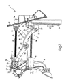
- the set of pedals 1 comprises a fixing plate 2, which enables anchorage of the set of pedals 1 itself to a fixed frame (not illustrated) of the motor vehicle (not illustrated), and supports a toothed guide rod 3, which projects from the plate 2 in a given direction 4, has a longitudinal axis 3a, and is provided with a toothing having, in longitudinal sectional view, a substantially V-shape.
- the rod 3 is slidably engaged by a slide 5, which extends in a direction 6 substantially transverse to the direction 4, has a central hole 5a ( Figure 4) made through the slide 5 and set so that it shares the axis 3a of the rod 3, supports, in the case in point, two pedals 7, 8 for acceleration and, respectively, braking of the motor vehicle (not illustrated), and is mobile along the rod 3 itself under the action of the thrust of an actuating device 9 that will be illustrated in greater detail in what follows.
- the slide 5 further supports a clutch pedal of the motor vehicle (not illustrated).
- the pedal 7 is a pedal of a known type, mounted on the slide 5 for oscillating, with respect to the slide 5 itself, about an axis 10 of fulcrum substantially parallel to the direction 6, and the pedal 8 is hinged, in a position corresponding to a free end of its own, to the slide 5 for oscillating, with respect to the slide 5 itself, about an axis 11 of fulcrum substantially parallel to the axis 10.
- the pedal 8 is hinged, moreover, in a position corresponding to an intermediate point thereof, to a sleeve 12 for oscillating, with respect to the sleeve 12 itself, about an axis 13 of fulcrum substantially parallel to the axis 11.
- the sleeve 12 is mounted coaxially to a toothed rod 14, which has a. longitudinal axis 14a parallel to the axis 3a, and is provided with a toothing having, in longitudinal sectional view, a substantially saw-toothed shape.
- the sleeve 12 is coupled in an axially slidable manner to the rod 14 to perform, along the rod 14 itself and under the action of the thrust of the device 9, rectilinear displacements in the direction 4, and is connectable (according to modalities that will be described in greater detail in what follows) to the rod 14 to impart on the rod 14 itself, following upon oscillation of the pedal 8 about the axis 11, rectilinear displacements in the direction 4 so as to control selectively operation of a braking device 15 of a known type.
- the actuating device 9 comprises a crank mechanism 16 comprising, in turn, a crank 17, hinged to the plate 2 for oscillating, with respect to the plate 2 itself, about an axis 18 of fulcrum substantially parallel to the direction 6, and a connecting rod 19, which is hinged, in a position corresponding to an intermediate point thereof, to one free end of the crank 17 for oscillating, with respect to the crank 17 itself, about an axis 20 of fulcrum parallel to the axis 18, and extends between two axes 21, 22 parallel to the axis 20, and of which the axis 21 is the axis of rotation of the connecting rod 19 with respect to the slide 5, and the axis 22 is the axis of rotation of the connecting rod 19 with respect to a pad 23 coupled slidably to a rectilinear guide 24 extending in a direction 25 orthogonal to the directions 4 and 6.
- the device 9 further comprises a clamping device 26, which enables blocking of the slide 5 along the rod 3, and comprises a plurality of gripping arms 27 (in the case in point, three arms 27), which are mounted within the hole 5a, are uniformly distributed around the rod 3 and hence around the axis 3a, and have respective toothed portions 28 set in a position facing the rod 3 itself.
- a clamping device 26 which enables blocking of the slide 5 along the rod 3, and comprises a plurality of gripping arms 27 (in the case in point, three arms 27), which are mounted within the hole 5a, are uniformly distributed around the rod 3 and hence around the axis 3a, and have respective toothed portions 28 set in a position facing the rod 3 itself.
- the arms 27 are hinged to the slide 5 for oscillating, with respect to the slide 5 itself and under the action of the thrust of an actuator device 29, about respective axes 30 of fulcrum transverse to the axis 3a itself between a position of clamping ( Figure 4b), in which the arms 27 set themselves at a distance from one another approximating by defect the diameter of the rod 3 so as to enable the portions 28 to engage the rod 3 itself, and a position of release ( Figure 4a), in which the arms 27 set themselves at a distance from one another approximating by excess the diameter of the rod 3 so as to enable the portions 28 to disengage the rod 3 itself.
- the device 29 comprises a mechanically actuated tubular piston 31, which is mounted, within the hole 5a, so that it shares the axis 3a of the rod 3, is coupled slidably to the rod 3, and is provided, in a position corresponding to a first free end of its own, with an annular flange 32 extending radially outwards from the outer surface of the piston 31, and, in a position corresponding to a second free end of its own, with a cup 33 fixed to the piston 31 itself perpendicular to the axis 3a.
- the piston 31 has a plurality of races 34, which are uniformly distributed about the axis 3a, are equal in number to the arms 27, are slidably engaged, each, by a respective arm 27, and comprise, each, a respective first stretch 34a made through the flange 32 parallel to the axis 3a and a respective second stretch 34b made through the piston 31 and inclined with respect to the axis 3a itself.
- the device 29 further comprises a spring 35, which is mounted within the hole 5a so that it shares the axis 3a of the rod 3, and is set between the cup 33 and an annular element 36 fixed within the hole 5a for displacing the piston 31 into, and normally maintaining it in, a resting position ( Figure 4b), in which the free ends of the arms 27 engage the corresponding stretches 34a and the portions 28 set themselves on the outside of the corresponding races 34 to engage the rod 3.
- a spring 35 which is mounted within the hole 5a so that it shares the axis 3a of the rod 3, and is set between the cup 33 and an annular element 36 fixed within the hole 5a for displacing the piston 31 into, and normally maintaining it in, a resting position (Figure 4b), in which the free ends of the arms 27 engage the corresponding stretches 34a and the portions 28 set themselves on the outside of the corresponding races 34 to engage the rod 3.
- the piston 31 is mobile, under the action of the thrust of a lever 37, hinged within the hole 5a for oscillating about an axis 38 of fulcrum transverse to the axis 3a and against the thrust of the spring 35, from the aforesaid resting position to an operative position ( Figure 4a), in which the free ends of the arms 27 engage the corresponding stretches 34b and the portions 28 engage the corresponding stretches 34a to disengage the rod 3.
- the lever 37 projects radially outwards from the slide 5 to be actuated by a cable 39 of a Bowden type designed to displace the lever 37 itself about the axis 38.
- the device 9 further comprises a clamping device 40, which enables blocking of the sleeve 12 along the rod 14 and comprises a plurality of gripping members 41 (in the case in point, three members 41), which are mounted within the sleeve 12, and are uniformly distributed around the rod 14.
- Each member 41 is limited radially by a toothed face 42, which extends parallel to the axis 14a and is set in a position facing the rod 14, and is limited axially by a substantially wedge-shaped portion 43 set in engagement with a race 44 shaped like a truncated cone made on the internal surface of the sleeve 12 and normally common to all the members 41.
- the members 41 are mobile, under the action of the thrust of an actuator device 45, between a position of clamping ( Figure 5a), in which the members 41 set themselves at a distance from one another approximating by defect the diameter of the rod 14 so as to enable the faces 42 to engage the rod 14 itself, and a position of release ( Figure 5b), in which the members 41 set themselves at a distance from one another, approximating by excess the diameter of the rod 14 so as to enable the faces 42 to disengage the rod 14 itself.
- the device 45 comprises: a mechanically actuated tubular piston 46, which is mounted within the sleeve 12 so that it shares the axis 14a of the rod 14, is coupled slidably to the rod 14, and is limited axially by a surface 47 substantially shaped like a truncated cone, set in engagement with the portions 43; and a spring 48, which is fitted on the rod 14 so that it shares the axis 14a of the rod 14 and is set between the sleeve 12 and the members 41 for displacing the members 41 themselves into, and normally maintaining them in, their clamping position, and for displacing the piston 46 into, and normally maintaining it in, a resting position ( Figure 5a).
- the piston 46 is mobile, under the action of the thrust of a lever 49, which extends through the sleeve 12 to be actuated by a cable 50 of a Bowden type, and against the thrust of the spring 48, from the aforesaid resting position to an operative position ( Figure 5b), in which the members 41 are displaced along the race 44 and into their position of release.
- the device 9 comprises a device 52 for clamping the pedal 8 about the axis 11, which in turn comprises a crank 53, which is hinged to the slide 5 for oscillating, with respect to the slide 5 itself, about an axis 54 of fulcrum parallel to the direction 6, and is mobile between a position of clamping ( Figure 4a), in which the crank 53 engages a pin 55 projecting from the pedal 8 parallel to the direction 6 itself, and a position of release ( Figures 1 and 4b).
- the crank 53 is actuated by the cable 39 via a pin 56, which is fixed to the cable 39 itself, extends parallel to the direction 6, and is mobile along a groove 57 made in the crank 53 so as to displace the device 52 into its clamping position, before displacing the devices 26 and 40 into their positions of release, and into its position of release, after displacing the devices 26 and 40 into their clamping positions.
- the device 26 is replaced with a clamping device designed to control selectively the position of the crank 17 about the axis 18.
- the rods 3 and 14 are replaced with two threaded rods, which are set in rotation by respective electric motors or, alternatively, by a single motor common to both of the threaded rods, and are coupled to the slide 5 and to the sleeve 12 via respective external-thread/internal-thread couplings.
- the driver of the motor vehicle actuates the cables 39 and 50 so as to displace, in the first place, the device 52 into its clamping position and prevent oscillation of the pedal 8 about the axis 11 and then displace the devices 26 and 40 into their positions of release.
- the crank mechanism 16 is displaced by the spring 51 into its operative position illustrated in Figures 1 and 2, the set of pedals 1 is displaced in the direction 4 by the driver via the engagement of the pedal 8, and, finally, once the desired position along the rod 3 has been reached, the cables 39 and 50 are released by the driver himself to enable, in the first place, the devices 26 and 40 to be set in their clamping positions and hence the device 52 to be set in its position of release.
- the set of pedals 1 presents a number of advantages chiefly deriving from the fact that the slide 5, and hence the axes 10, 11 of fulcrum of the pedal 7 and, respectively, of the pedal 8, are displaced along a rectilinear path parallel to the direction 4, and from the fact that the crank mechanism 16 enables, in a simple and inexpensive way, relatively extensive displacements of the slide 5 in the direction 4.
Landscapes
- Engineering & Computer Science (AREA)
- Transportation (AREA)
- Mechanical Engineering (AREA)
- Mechanical Control Devices (AREA)
- Auxiliary Drives, Propulsion Controls, And Safety Devices (AREA)
- Body Structure For Vehicles (AREA)
Claims (17)
- Einstellbare Pedalgruppe für ein Kraftfahrzeug, wobei die einstellbare Pedalgruppe umfasst:ein erstes Pedal (8) zum Bremsen des Kraftfahrzeugs;ein zweites Pedal (7) zum Beschleunigen des Kraftfahrzeugs;Mittel (5) zum Unterstützen des ersten und des zweiten Pedals (8, 7); undeine Einstellvorrichtung (9) zum wahlweisen Steuern der Position der Unterstützungsmittel (5) in Bezug auf einen Rahmen (2) des Kraftfahrzeugs, die einen Kurbelmechanismus (16) umfasst, der zwischen die Unterstützungsmittel (5) und den Rahmen (2) eingesetzt ist;wobei die einstellbare Pedalgruppe dadurch gekennzeichnet ist, dass die Einstellvorrichtung (9) umfasst:eine erste Führung (3), die sich in einer ersten Richtung (4) erstreckt und die Unterstützungsmittel (5), die längs der ersten Führung (3) beweglich sind, unterstützt; undeinen Steuerstab (14), der zu der ersten Richtung (4) parallel ist und durch das erste Pedal (8) in einem Gleiteingriff ist und mit dem ersten Pedal (8) verbunden werden kann, um eine Bremsvorrichtung (15) des Kraftfahrzeugs zu betätigen.
- Einstellbare Pedalgruppe nach Anspruch 1, bei der die erste Führung (3) eine erste Schraube umfasst, die so angebracht ist, dass sie sich um eine erste Längsachse (3a) drehen kann; wobei die Unterstützungsmittel (5) mit der ersten Schraube über eine erste Außengewinde-/Innengewinde-Kopplung gekoppelt sind.
- Einstellbare Pedalgruppe nach Anspruch 1 oder Anspruch 2, bei der die Einstellvorrichtung (9) ferner umfasst: eine zweite Führung (24), die sich in einer zu der ersten Richtung (4) im Wesentlichen quer orientierten zweiten Richtung (25) erstreckt; und einen Gleiter (23), der so angebracht ist, dass er längs der zweiten Führung (24) unter der Wirkung des Schubs des Kurbelmechanismus (16) gleiten kann.
- Einstellbare Pedalgruppe nach Anspruch 3, bei der der Kurbelmechanismus (16) einen Verbindungsstab (19), der zwischen die Unterstützungsmittel (5) und den Gleiter (23) eingesetzt ist; und eine Kurbel (17), die zwischen den Rahmen (2) und den Verbindungsstab (19) eingesetzt ist, umfasst.
- Einstellbare Pedalgruppe nach Anspruch 3 oder Anspruch 4, bei der die Unterstützungsmittel (5) unter der Wirkung des Schubs des Kurbelmechanismus (16) zwischen einer ersten Endposition und einer zweiten Endposition beweglich sind; und Schubmittel (51) vorgesehen sind, um die Unterstützungsmittel (5) entweder in die erste oder in die zweite Endposition zu verlagern und sie dort normalerweise zu halten.
- Einstellbare Pedalgruppe nach Anspruch 5, bei der die Schubmittel (51) elastische Schubmittel sind, die zwischen den Gleiter (23) und den Kurbelmechanismus (16) eingesetzt sind.
- Einstellbare Pedalgruppe nach einem der Ansprüche 1 bis 6, bei der die Einstellvorrichtung (9) ferner erste Feststellmittel (26) zum Blockieren der Unterstützungsmittel (5) längs der ersten Führung (3); und eine erste Betätigungsvorrichtung (29) zum Betätigen der ersten Feststellmittel (26) zwischen einer ersten Feststellposition der Unterstützungsmittel (5) längs der ersten Führung (3) und einer ersten Freigabeposition umfasst.
- Einstellbare Pedalgruppe nach Anspruch 7, bei der die ersten Feststellmittel (26) mehrere erste Feststellorgane (27), die von den Unterstützungsmitteln (5) getragen werden und um die erste Führung (3) verteilt sind und von der ersten Führung (3) weg und zu ihr hin beweglich sind, umfassen und die erste Betätigungsvorrichtung (29) erste Betätigungsmittel (31, 37) zum Verlagern der ersten Feststellorgane (27) aus der ersten Feststellposition in die erste Freigabeposition und zweite Betätigungsmittel (35) zum Verlagern der ersten Feststellorgane (27) aus der ersten Freigabeposition in die erste Feststellposition umfasst.
- Einstellbare Pedalgruppe nach Anspruch 7 oder Anspruch 8, die ferner zweite Feststellmittel (40) zum Blockieren des ersten Pedals (8) längs des Steuerstabs (14); und eine zweite Betätigungsvorrichtung (45) zum Betätigen der zweiten Feststellmittel (40) zwischen einer zweiten Feststellposition des ersten Pedals (8) längs des Steuerstabs (14) und einer zweiten Freigabeposition umfasst.
- Einstellbare Pedalgruppe nach Anspruch 9, bei der die zweiten Feststellmittel (40) mehrere zweite Feststellorgane (41), die von dem ersten Pedal (8) getragen werden, um den Steuerstab (14) verteilt sind und von dem Steuerstab (14) weg und zu ihm hin beweglich sind, umfasst und die zweite Betätigungsvorrichtung (45) dritte Betätigungsmittel (46, 49) zum Verlagern der zweiten Feststellorgane (41) aus der zweiten Feststellposition in die zweite Freigabeposition und vierte Betätigungsmittel (48) zum Verlagern der zweiten Feststellorgane (41) aus der zweiten Freigabeposition in die zweite Feststellposition umfasst.
- Einstellbare Pedalgruppe nach Anspruch 9 oder Anspruch 10, bei der das erste Pedal (8) an den Unterstützungsmitteln (5) drehbar angebracht ist, um um eine zweite Drehachse (11) zu oszillieren; dritte Feststellmittel (52) vorgesehen sind, um das erste Pedal (8) um die Drehachse (11) in Drehrichtung zu blockieren, und eine dritte Betätigungsvorrichtung (39) so entworfen ist, dass sie die dritten Feststellmittel (52) zwischen einer dritten Feststellposition des ersten Pedals (8) um die zweite Drehachse (11) und einer dritten Freigabeposition betätigt.
- Einstellbare Pedalgruppe nach Anspruch 11, bei der die erste, die zweite und die dritte Betätigungsvorrichtung (29, 45, 39) miteinander verbunden sind, um die dritten Feststellmittel (52) in die entsprechende Feststellposition zu verlagern, wenn die ersten und die zweiten Feststellmittel (26, 40) in ihre entsprechenden Freigabepositionen verlagert sind, und in die entsprechende Freigabeposition zu verlagern, wenn die ersten und die zweiten Feststellmittel (26, 40) in ihre entsprechenden Feststellpositionen verlagert sind.
- Einstellbare Pedalgruppe nach einem der Ansprüche 1 bis 12, bei der die erste Richtung (4) eine im Wesentlichen geradlinige Richtung ist.
- Einstellbare Pedalgruppe nach einem der Ansprüche 1 bis 13, bei der das erste Pedal (8) mit dem Steuerstab (14) über eine zweite Außengewinde-/lnnengewinde-Kopplung gekoppelt ist.
- Einstellbare Pedalgruppe nach einem der Ansprüche 1 bis 14, bei der das erste Pedal (8) an den Unterstützungsmitteln (5) angelenkt ist, um um eine zweite Drehachse (11) zu oszillieren, und das zweite Pedal (7) an den Unterstützungsmitteln (5) angelenkt ist, um in Bezug auf die Unterstützungsmittel (5) um eine vierte Drehachse (10), die zu der zweiten Drehachse (11) parallel ist, zu oszillieren.
- Einstellbare Pedalgruppe nach Anspruch 15, bei der das erste Pedal (8) darüber hinaus in einer Position, die einem Zwischenpunkt hiervon entspricht, an einer Hülse (12) angelenkt ist, die längs des Steuerstabs (14) gleiten kann, um in Bezug auf die Hülse (12) um eine fünfte Drehachse (13) zu oszillieren, die zu der zweiten Drehachse (11) im Wesentlichen parallel ist.
- Einstellbare Pedalgruppe nach Anspruch 16, bei der die Hülse (12) auf eine axial gleitende Weise mit dem Steuerstab (14) gekoppelt ist, um geradlinige Verlagerungen längs des Steuerstabs (14) auszuführen, und mit dem Steuerstab (14) verbunden werden kann, um auf den Steuerstab (14) in Folge einer Oszillation des ersten Pedals (8) um die zweite Drehachse (11) geradlinige Verlagerungen auszuüben, um den Betrieb einer Bremsvorrichtung (15) wahlweise zu steuern.
Applications Claiming Priority (2)
| Application Number | Priority Date | Filing Date | Title |
|---|---|---|---|
| IT000763A ITBO20030763A1 (it) | 2003-12-19 | 2003-12-19 | Pedaliera regolabile per un autoveicolo |
| PCT/IB2004/004195 WO2005061292A1 (en) | 2003-12-19 | 2004-12-15 | An adjustable set of pedals for a motor vehicle |
Publications (2)
| Publication Number | Publication Date |
|---|---|
| EP1699668A1 EP1699668A1 (de) | 2006-09-13 |
| EP1699668B1 true EP1699668B1 (de) | 2007-09-19 |
Family
ID=34708502
Family Applications (1)
| Application Number | Title | Priority Date | Filing Date |
|---|---|---|---|
| EP04801412A Expired - Lifetime EP1699668B1 (de) | 2003-12-19 | 2004-12-15 | Einstellbarer pedalensatz für ein kraftfahrzeug |
Country Status (6)
| Country | Link |
|---|---|
| US (1) | US20080022804A1 (de) |
| EP (1) | EP1699668B1 (de) |
| JP (1) | JP2007514604A (de) |
| DE (1) | DE602004009101T2 (de) |
| IT (1) | ITBO20030763A1 (de) |
| WO (1) | WO2005061292A1 (de) |
Families Citing this family (2)
| Publication number | Priority date | Publication date | Assignee | Title |
|---|---|---|---|---|
| FR2903062B1 (fr) * | 2006-06-30 | 2008-08-29 | Peugeot Citroen Automobiles Sa | Dispositif de pedalier retractable en cas de choc frontal sur un vehicule |
| DE102018203559A1 (de) * | 2018-03-08 | 2019-09-12 | Volkswagen Aktiengesellschaft | Verstaubares Bremspedal |
Family Cites Families (23)
| Publication number | Priority date | Publication date | Assignee | Title |
|---|---|---|---|---|
| US2694946A (en) * | 1951-07-11 | 1954-11-23 | Joseph D Vandal | Portable dual control mechanism |
| US2860720A (en) * | 1956-01-18 | 1958-11-18 | Gen Motors Corp | Adjustable toeboard for an automobile |
| US3151499A (en) * | 1962-11-13 | 1964-10-06 | Gen Motors Corp | Adjustable pedal for vehicle |
| US3643524A (en) * | 1970-05-26 | 1972-02-22 | Gen Motors Corp | Control pedals for vehicles |
| US3643525A (en) * | 1970-05-26 | 1972-02-22 | Gen Motors Corp | Adjustable control pedals for vehicles |
| US3975972A (en) * | 1975-04-16 | 1976-08-24 | Muhleck Earl M | Adjustable pedal construction |
| US4312246A (en) * | 1979-12-26 | 1982-01-26 | Barresi Zina V | Dual operating system for controlling a brake or the like, including a counter system to prevent or reverse operation |
| EP0363546A1 (de) * | 1987-05-22 | 1990-04-18 | Wickes Manufacturing Company | Einstellbare Vorrichtung für Brems- und Gaspedal |
| US5460061A (en) * | 1993-09-17 | 1995-10-24 | Comfort Pedals, Inc. | Adjustable control pedal apparatus |
| US5819881A (en) * | 1995-07-24 | 1998-10-13 | P. L. Porter Co. | Dual locking linear mechanical lock for high loads |
| US5634534A (en) * | 1996-04-09 | 1997-06-03 | Tachi-S Co., Ltd. | Longitudinal locking mechanism for vehicle seat |
| DE19631212C1 (de) * | 1996-08-02 | 1997-12-18 | Daimler Benz Ag | Fahrpedaleinheit |
| US6293584B1 (en) * | 1998-09-23 | 2001-09-25 | Vehicle Safety Systems, Inc. | Vehicle air bag minimum distance enforcement apparatus, method and system |
| US6189409B1 (en) * | 1999-01-11 | 2001-02-20 | Daimlerchrysler Corporation | Adjustable pedal system |
| US6151985A (en) * | 1999-04-01 | 2000-11-28 | Daimlerchrysler Corporation | Adjustable pedal apparatus |
| US6360629B2 (en) * | 1999-04-01 | 2002-03-26 | Daimlerchrysler Corporation | Adjustable pedal apparatus |
| DE10026751A1 (de) * | 2000-05-30 | 2001-12-06 | Wolf Woco & Co Franz J | Pedalerie und Pedalsystem mit einer Vielzahl von solchen Pedalerien |
| DE10033703B4 (de) * | 2000-07-12 | 2006-08-24 | Fico Cables, S.A., Rubi | Verstellbares Pedal |
| US20040040400A1 (en) * | 2000-09-22 | 2004-03-04 | Karlheninz Pilz | Driving school vehicle, double pedal device, pedal box, adjuster and driving instructor post for use in the driving school vehicle |
| US6443028B1 (en) * | 2000-10-02 | 2002-09-03 | General Motors Corporation | Adjustable control pedal assembly for motor vehicle |
| US6962094B2 (en) * | 2001-01-24 | 2005-11-08 | Orscheln Products Llc | Adjustable pedal assembly |
| US6722226B2 (en) * | 2001-09-24 | 2004-04-20 | Daimlerchrysler Corporation | Adjustable pedal assembly |
| US7111524B2 (en) * | 2002-07-03 | 2006-09-26 | Dura Global Technologies, Inc. | Cable actuated adjustable pedal |
-
2003
- 2003-12-19 IT IT000763A patent/ITBO20030763A1/it unknown
-
2004
- 2004-12-15 JP JP2006544596A patent/JP2007514604A/ja active Pending
- 2004-12-15 US US10/583,550 patent/US20080022804A1/en not_active Abandoned
- 2004-12-15 EP EP04801412A patent/EP1699668B1/de not_active Expired - Lifetime
- 2004-12-15 WO PCT/IB2004/004195 patent/WO2005061292A1/en not_active Ceased
- 2004-12-15 DE DE602004009101T patent/DE602004009101T2/de not_active Expired - Lifetime
Also Published As
| Publication number | Publication date |
|---|---|
| US20080022804A1 (en) | 2008-01-31 |
| DE602004009101T2 (de) | 2008-06-19 |
| ITBO20030763A1 (it) | 2005-06-20 |
| JP2007514604A (ja) | 2007-06-07 |
| WO2005061292A1 (en) | 2005-07-07 |
| WO2005061292A8 (en) | 2005-12-01 |
| DE602004009101D1 (de) | 2007-10-31 |
| EP1699668A1 (de) | 2006-09-13 |
Similar Documents
| Publication | Publication Date | Title |
|---|---|---|
| CA2119237C (en) | Adjustable automobile pedal system | |
| US3354981A (en) | Hand control mechanism for vehicle with hydrostatic transmission | |
| US20050199088A1 (en) | Adjustable pedal assembly | |
| JP2003530633A (ja) | 自動車用の調整可能ペダル組立体 | |
| JP2000515223A (ja) | 内部で枢動することにより、サイド荷重に対して自動的に調節されるアクチュエータ | |
| HU205310B (en) | Electromechanical brake assembly first for railway vehicles | |
| WO2007034567A1 (ja) | 自動車車両ドライブバイワイヤー操舵システム | |
| US6631654B2 (en) | Driving position selector with an emergency release for a parking position | |
| US4946013A (en) | Apparatus for manual operation of vehicle brake and accelerator pedals | |
| EP1699668B1 (de) | Einstellbarer pedalensatz für ein kraftfahrzeug | |
| US3541881A (en) | Adjustable pedal | |
| US6848545B2 (en) | Brake actuation assembly for a vehicle | |
| US6431022B1 (en) | Compact adjustable pedal system | |
| US20020023516A1 (en) | Adjustable foot-operated control mechanism | |
| JP2003502762A (ja) | 自動車用操作装置 | |
| JP2008114846A (ja) | 乗用田植機の無段変速操作装置 | |
| RU2295459C2 (ru) | Устройство управления со средствами его фиксации и регулировки | |
| JP3703681B2 (ja) | 前後調節可能な車両用ペダル装置 | |
| US7066048B2 (en) | Brake pedal designed to equip a motor vehicle | |
| DE102010020669A1 (de) | Vorrichtung zum Bremsen, Lenken und Fesstellen eines manuellen Rollstuhls | |
| EP2477830B1 (de) | Manuelle vorrichtung zur brems- und beschleunigungssteuerung bei einem fahrzeug | |
| RU110035U1 (ru) | Устройство для ручного управления рабочими приводами тормоза, сцепления и дроссельной заслонкой автомобиля | |
| KR100511857B1 (ko) | 자동차의 브레이크 페달 시스템 | |
| JP4003391B2 (ja) | 可動ペダル装置 | |
| JPH02116911A (ja) | 前後調節可能な足踏み式ペダル |
Legal Events
| Date | Code | Title | Description |
|---|---|---|---|
| PUAI | Public reference made under article 153(3) epc to a published international application that has entered the european phase |
Free format text: ORIGINAL CODE: 0009012 |
|
| 17P | Request for examination filed |
Effective date: 20060718 |
|
| AK | Designated contracting states |
Kind code of ref document: A1 Designated state(s): DE ES FR GB SE |
|
| DAX | Request for extension of the european patent (deleted) | ||
| RBV | Designated contracting states (corrected) |
Designated state(s): DE ES FR GB SE |
|
| GRAP | Despatch of communication of intention to grant a patent |
Free format text: ORIGINAL CODE: EPIDOSNIGR1 |
|
| GRAS | Grant fee paid |
Free format text: ORIGINAL CODE: EPIDOSNIGR3 |
|
| GRAA | (expected) grant |
Free format text: ORIGINAL CODE: 0009210 |
|
| AK | Designated contracting states |
Kind code of ref document: B1 Designated state(s): DE ES FR GB SE |
|
| REG | Reference to a national code |
Ref country code: GB Ref legal event code: FG4D |
|
| REF | Corresponds to: |
Ref document number: 602004009101 Country of ref document: DE Date of ref document: 20071031 Kind code of ref document: P |
|
| PG25 | Lapsed in a contracting state [announced via postgrant information from national office to epo] |
Ref country code: ES Free format text: LAPSE BECAUSE OF FAILURE TO SUBMIT A TRANSLATION OF THE DESCRIPTION OR TO PAY THE FEE WITHIN THE PRESCRIBED TIME-LIMIT Effective date: 20071230 |
|
| EN | Fr: translation not filed | ||
| PG25 | Lapsed in a contracting state [announced via postgrant information from national office to epo] |
Ref country code: SE Free format text: LAPSE BECAUSE OF FAILURE TO SUBMIT A TRANSLATION OF THE DESCRIPTION OR TO PAY THE FEE WITHIN THE PRESCRIBED TIME-LIMIT Effective date: 20071219 |
|
| PLBE | No opposition filed within time limit |
Free format text: ORIGINAL CODE: 0009261 |
|
| STAA | Information on the status of an ep patent application or granted ep patent |
Free format text: STATUS: NO OPPOSITION FILED WITHIN TIME LIMIT |
|
| 26N | No opposition filed |
Effective date: 20080620 |
|
| PG25 | Lapsed in a contracting state [announced via postgrant information from national office to epo] |
Ref country code: FR Free format text: LAPSE BECAUSE OF FAILURE TO SUBMIT A TRANSLATION OF THE DESCRIPTION OR TO PAY THE FEE WITHIN THE PRESCRIBED TIME-LIMIT Effective date: 20080523 |
|
| P01 | Opt-out of the competence of the unified patent court (upc) registered |
Effective date: 20230525 |
|
| PGFP | Annual fee paid to national office [announced via postgrant information from national office to epo] |
Ref country code: GB Payment date: 20231219 Year of fee payment: 20 |
|
| PGFP | Annual fee paid to national office [announced via postgrant information from national office to epo] |
Ref country code: DE Payment date: 20231227 Year of fee payment: 20 |
|
| REG | Reference to a national code |
Ref country code: DE Ref legal event code: R071 Ref document number: 602004009101 Country of ref document: DE |
|
| REG | Reference to a national code |
Ref country code: GB Ref legal event code: PE20 Expiry date: 20241214 |
|
| PG25 | Lapsed in a contracting state [announced via postgrant information from national office to epo] |
Ref country code: GB Free format text: LAPSE BECAUSE OF EXPIRATION OF PROTECTION Effective date: 20241214 |
|
| PG25 | Lapsed in a contracting state [announced via postgrant information from national office to epo] |
Ref country code: GB Free format text: LAPSE BECAUSE OF EXPIRATION OF PROTECTION Effective date: 20241214 |