EP1699645B1 - Fahrzeugreifen - Google Patents
Fahrzeugreifen Download PDFInfo
- Publication number
- EP1699645B1 EP1699645B1 EP04803958A EP04803958A EP1699645B1 EP 1699645 B1 EP1699645 B1 EP 1699645B1 EP 04803958 A EP04803958 A EP 04803958A EP 04803958 A EP04803958 A EP 04803958A EP 1699645 B1 EP1699645 B1 EP 1699645B1
- Authority
- EP
- European Patent Office
- Prior art keywords
- tyre
- layer
- carcass
- reinforcement
- angles
- Prior art date
- Legal status (The legal status is an assumption and is not a legal conclusion. Google has not performed a legal analysis and makes no representation as to the accuracy of the status listed.)
- Not-in-force
Links
- 230000002787 reinforcement Effects 0.000 claims abstract description 82
- 239000011324 bead Substances 0.000 claims abstract description 13
- 239000000463 material Substances 0.000 claims description 8
- 239000004753 textile Substances 0.000 claims description 6
- 239000002184 metal Substances 0.000 claims description 3
- 230000003014 reinforcing effect Effects 0.000 abstract description 58
- 239000010410 layer Substances 0.000 description 106
- 238000000034 method Methods 0.000 description 17
- 238000004519 manufacturing process Methods 0.000 description 11
- 238000004873 anchoring Methods 0.000 description 5
- 230000008569 process Effects 0.000 description 5
- 239000011265 semifinished product Substances 0.000 description 5
- 238000010586 diagram Methods 0.000 description 4
- 239000000203 mixture Substances 0.000 description 4
- 239000000047 product Substances 0.000 description 4
- 230000009993 protective function Effects 0.000 description 4
- 230000004048 modification Effects 0.000 description 3
- 238000012986 modification Methods 0.000 description 3
- 238000013459 approach Methods 0.000 description 2
- 230000000712 assembly Effects 0.000 description 2
- 238000000429 assembly Methods 0.000 description 2
- 230000008859 change Effects 0.000 description 2
- 238000013461 design Methods 0.000 description 2
- 238000009826 distribution Methods 0.000 description 2
- 238000005304 joining Methods 0.000 description 2
- 239000004953 Aliphatic polyamide Substances 0.000 description 1
- 238000004026 adhesive bonding Methods 0.000 description 1
- 230000016571 aggressive behavior Effects 0.000 description 1
- 229920003231 aliphatic polyamide Polymers 0.000 description 1
- 239000004760 aramid Substances 0.000 description 1
- 229920003235 aromatic polyamide Polymers 0.000 description 1
- 238000005119 centrifugation Methods 0.000 description 1
- 239000011248 coating agent Substances 0.000 description 1
- 238000000576 coating method Methods 0.000 description 1
- 239000002131 composite material Substances 0.000 description 1
- 238000007796 conventional method Methods 0.000 description 1
- 238000005520 cutting process Methods 0.000 description 1
- 238000013016 damping Methods 0.000 description 1
- 238000011161 development Methods 0.000 description 1
- 230000018109 developmental process Effects 0.000 description 1
- 230000002708 enhancing effect Effects 0.000 description 1
- 239000000835 fiber Substances 0.000 description 1
- 230000006870 function Effects 0.000 description 1
- 230000006872 improvement Effects 0.000 description 1
- 238000009776 industrial production Methods 0.000 description 1
- 238000012423 maintenance Methods 0.000 description 1
- 230000007935 neutral effect Effects 0.000 description 1
- 238000002360 preparation method Methods 0.000 description 1
- 239000011241 protective layer Substances 0.000 description 1
- 230000009467 reduction Effects 0.000 description 1
- 238000005096 rolling process Methods 0.000 description 1
- 239000002356 single layer Substances 0.000 description 1
- 238000004381 surface treatment Methods 0.000 description 1
- 230000002747 voluntary effect Effects 0.000 description 1
- 238000004073 vulcanization Methods 0.000 description 1
- 238000004804 winding Methods 0.000 description 1
Images


Classifications
-
- B—PERFORMING OPERATIONS; TRANSPORTING
- B60—VEHICLES IN GENERAL
- B60C—VEHICLE TYRES; TYRE INFLATION; TYRE CHANGING; CONNECTING VALVES TO INFLATABLE ELASTIC BODIES IN GENERAL; DEVICES OR ARRANGEMENTS RELATED TO TYRES
- B60C15/00—Tyre beads, e.g. ply turn-up or overlap
- B60C15/0009—Tyre beads, e.g. ply turn-up or overlap features of the carcass terminal portion
- B60C15/0018—Tyre beads, e.g. ply turn-up or overlap features of the carcass terminal portion not folded around the bead core, e.g. floating or down ply
-
- B—PERFORMING OPERATIONS; TRANSPORTING
- B60—VEHICLES IN GENERAL
- B60C—VEHICLE TYRES; TYRE INFLATION; TYRE CHANGING; CONNECTING VALVES TO INFLATABLE ELASTIC BODIES IN GENERAL; DEVICES OR ARRANGEMENTS RELATED TO TYRES
- B60C3/00—Tyres characterised by the transverse section
- B60C3/06—Tyres characterised by the transverse section asymmetric
-
- B—PERFORMING OPERATIONS; TRANSPORTING
- B60—VEHICLES IN GENERAL
- B60C—VEHICLE TYRES; TYRE INFLATION; TYRE CHANGING; CONNECTING VALVES TO INFLATABLE ELASTIC BODIES IN GENERAL; DEVICES OR ARRANGEMENTS RELATED TO TYRES
- B60C9/00—Reinforcements or ply arrangement of pneumatic tyres
- B60C9/02—Carcasses
- B60C9/04—Carcasses the reinforcing cords of each carcass ply arranged in a substantially parallel relationship
- B60C9/08—Carcasses the reinforcing cords of each carcass ply arranged in a substantially parallel relationship the cords extend transversely from bead to bead, i.e. radial ply
-
- B—PERFORMING OPERATIONS; TRANSPORTING
- B60—VEHICLES IN GENERAL
- B60C—VEHICLE TYRES; TYRE INFLATION; TYRE CHANGING; CONNECTING VALVES TO INFLATABLE ELASTIC BODIES IN GENERAL; DEVICES OR ARRANGEMENTS RELATED TO TYRES
- B60C9/00—Reinforcements or ply arrangement of pneumatic tyres
- B60C9/18—Structure or arrangement of belts or breakers, crown-reinforcing or cushioning layers
- B60C9/20—Structure or arrangement of belts or breakers, crown-reinforcing or cushioning layers built-up from rubberised plies each having all cords arranged substantially parallel
-
- Y—GENERAL TAGGING OF NEW TECHNOLOGICAL DEVELOPMENTS; GENERAL TAGGING OF CROSS-SECTIONAL TECHNOLOGIES SPANNING OVER SEVERAL SECTIONS OF THE IPC; TECHNICAL SUBJECTS COVERED BY FORMER USPC CROSS-REFERENCE ART COLLECTIONS [XRACs] AND DIGESTS
- Y10—TECHNICAL SUBJECTS COVERED BY FORMER USPC
- Y10S—TECHNICAL SUBJECTS COVERED BY FORMER USPC CROSS-REFERENCE ART COLLECTIONS [XRACs] AND DIGESTS
- Y10S152/00—Resilient tires and wheels
- Y10S152/19—Sandwich breakers
-
- Y—GENERAL TAGGING OF NEW TECHNOLOGICAL DEVELOPMENTS; GENERAL TAGGING OF CROSS-SECTIONAL TECHNOLOGIES SPANNING OVER SEVERAL SECTIONS OF THE IPC; TECHNICAL SUBJECTS COVERED BY FORMER USPC CROSS-REFERENCE ART COLLECTIONS [XRACs] AND DIGESTS
- Y10—TECHNICAL SUBJECTS COVERED BY FORMER USPC
- Y10T—TECHNICAL SUBJECTS COVERED BY FORMER US CLASSIFICATION
- Y10T152/00—Resilient tires and wheels
- Y10T152/10—Tires, resilient
- Y10T152/10495—Pneumatic tire or inner tube
- Y10T152/10765—Characterized by belt or breaker structure
- Y10T152/10783—Reinforcing plies made up from wound narrow ribbons
Definitions
- the tires described in this document do not have the "traditional" reversal of carcass ply around a rod.
- This type of anchorage is replaced by an arrangement in which is disposed adjacent to said sidewall reinforcing structure circumferential son, all being embedded in a rubber mix anchoring or bonding.
- anchoring zone can refer to both the “traditional” reversal of carcass ply around a rod of a conventional process, that the assembly formed by the circumferential reinforcing elements, the mixture rubbery and adjacent portions of sidewall reinforcement of a low zone made with a method with application to a toroidal core.
- the longitudinal direction of the tire is the direction corresponding to the periphery of the tire and defined by the rolling direction of the tire.
- the transverse or axial direction of the tire is parallel to the axis of rotation of the tire.
- a continuous carcass-type reinforcement structure is formed of continuous reinforcement elements from one bead to the other.
- wire generally refers to both mono-filaments, multifilamentary fibers (possibly twisted on themselves) or assemblies such as textile or metal cords, twists or any type of equivalent assembly such as a hybrid cable, and this, whatever the material or materials, the possible treatment of these son, for example a surface treatment or coating, or pre-gluing, to promote adhesion to the rubber or any other material.
- the tire according to the invention allows an economic gain of two orders. Firstly, the amount of material used to produce a layer of work reinforcing elements is reduced compared to a conventional tire, the same dimensions, because of the radially inner position of at least a portion of a layer of work-reinforcing elements with respect to the carcass-type reinforcement structure. And, consequently, the manufacturing time of said layer of work reinforcing elements may be less than that necessary for producing the layer of a conventional tire, particularly in the case of a hard core embodiment.
- the working layer is made with at least one wire of which no free end is present on the edges of said layer.
- the embodiment of the layer is made with a single wire and the layer is of the "single-wire" type.
- the industrial production of such layers leads to discontinuities, in particular due to coil changes.
- a preferred embodiment of the invention is still to use only one or a small number of son for a working layer and it is appropriate to have the beginnings and ends of son in the central zone of said layer.
- the sections In the central zone of the working layers, that is to say in the part of the working layers which does not encompass the loops connecting the sections together, the sections have identical angles formed with the longitudinal direction, said angles being measured at the points of intersection with a circumferential plane, regardless of said circumferential plane. In other words, for a given circumferential plane of section, the sections all have the same angle formed with the longitudinal direction at the points of intersection with said circumferential cutting plane. Moreover, the aforementioned angle may vary according to the circumferential section plane considered.
- the sections are equidistant from each other in circumferential sectional planes; the distance separating adjacent sections that may vary according to the circumferential plane of section considered, or more precisely, the distance between adjacent sections may vary in the axial direction.
- Such a tire which is advantageously made according to a technique of the type on hard or toroidal core notably allows the establishment of the reinforcing elements in the near-final position; indeed, a conformation step is not required according to this type of method the reinforcing elements are no longer moved after their introduction.
- a technique of the hard core type in particular allows simple variations of angles much greater than what is possible to obtain according to methods comprising a conformation step.
- said angle variations said angle tending to 90 ° to the edges of the working layers, leads to an increase in pitch and promotes the production of loops, because of the reduction in size.
- a first embodiment of the embodiments of the invention according to which the angles formed by said sections of the wire of the working layers with the longitudinal direction are variable in the transverse direction, consists in varying the angle of the sections of a monotonically from the equatorial plane of the tire to the edges of the working layer.
- the sections form an angle with the longitudinal direction of between 20 and 75 °.
- the angle is less than 50 ° and more preferably less than 40 °.
- the crown reinforcement structure of the tire comprises at least two layers of reinforcing elements such that from one layer to the next, the sections form between them angles of between 20 and 160 ° and preferably between 40 and 100 °.
- the reinforcing elements of the working layers are made of textile material.
- the reinforcement elements of the working layers are made of metal.
- At least one layer of work-reinforcing elements is positioned at least partially radially inside at least two carcass-type reinforcing layers.
- a tire according to the invention comprising at least a portion of the crown reinforcement structure made radially inside the carcass-type reinforcement structure, is thus advantageously produced according to a hard core or shape-type manufacturing technique. rigid.
- the crown reinforcement structure is integrally formed radially inside at least one carcass structure, that is to say within at least one carcass layer. At least one carcass-type reinforcement structure thus radially covers the complete crown reinforcement structure.
- the invention further provides, in the case of a layer of work reinforcing elements made in several parts placed in different radial positions, that the distribution of these different parts is not carried out symmetrically with respect to the equatorial plane, or circumferential plane passing through the center of the crown of the tire.
- Such a non-symmetrical distribution may also be related to a choice of materials different from the reinforcing elements of the working layers.
- the figure 1 represents a tire 1 comprising a carcass reinforcement consisting of a single layer 2 comprising textile-type reinforcing elements.
- the layer 2 consists of reinforcing elements arranged radially.
- the radial positioning of the reinforcing elements is defined by the angle of application of said reinforcing elements; a radial arrangement corresponds to an angle of application of said elements with respect to the longitudinal direction of the tire of between 65 ° and 90 °.
- Said carcass layer 2 is anchored on each side of the tire 1 in a bead 3 whose base is intended to be mounted on a rim seat.
- Each bead 3 is extended radially outwardly by a sidewall 4, said sidewall 4 radially outwardly joining the tread 5.
- the tire 1 thus formed has a curvature value greater than 0.15 and preferably greater than 0.3.
- the value of curvature is defined by the ratio Ht / Wt, that is to say by the ratio of the height of the tread on the maximum width of the tread of the tire.
- the value of curvature will advantageously be between 0.25 and 0.5 for a tire intended to be mounted at the front of a motorcycle and it will advantageously be between 0.2 and 0.5 for a tire intended to be mounted at the rear.
- the tire 1 further comprises under the tread a crown reinforcement constituted in this case by two working layers 6, 7.
- Said working layers 6, 7 are, according to the invention, positioned radially inside. of the portion of the carcass layer 2 radially external to the two points of tangency A, B of the curvilinear abscissa of said carcass layer 2 with the perpendiculars 100, 101 to the axis of rotation.
- the working layers 6, 7 consist of textile reinforcements made according to the invention with at least one continuous reinforcing thread forming parallel sections in the central zone of said layer and the adjacent sections being connected by loops.
- the arrangement of the son is such that the sections are crossed from one layer 6 to the next layer 7.
- the largest angles at the edge of the working layer 6 and advantageously at the level of the shoulders make it possible to promote the adhesion and the traction of the tire in camber by optimizing the shear stiffness of the working layers when the angle is around 45 ° or to promote comfort in camber when the angle approaches 90 °.
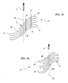
- the figure 2a also shows when the layer 6 is centered on the vertex or equator of the tire that the equator forms a line 12 comprising the points of inflection of the sections 10 formed by the wire 9.
- the figure 2b illustrates another embodiment of the invention similar to that of the figure 2a according to which the length of the sections is not regular.
- the wire 9 ' is deposited to form sections 10', 10 "of two different lengths
- Such a configuration makes it possible to obtain density variations in the axial direction, the quantity of reinforcement elements varying along this same direction. Density variations of this type are all the more interesting in the design of motorcycle tires to optimize and adapt different stiffnesses of the required working layers between the straight-line positions and the various inclined positions of the tire because of the different parts of the tire. the tread and reinforcing structure that are facing the ground.
- the production of the layers 6 and 6 ' is preferably carried out with a single wire.
- the ends of said son are in the central portion of the tire. More precisely, no free end appears on the edges of the working layers; only the loops 11, 11 'are present at this level of working layers.
- the figure 4 represents an embodiment of the invention according to which the working layer 64 is made in several parts 64a, 64b, 64c placed on the tire 14 at radially different levels.
- Such embodiments make it possible, for example, to locally retain a role of protecting the working layer 64, in particular with respect to the carcass ply 24, and also to reduce the manufacturing costs by partially realizing said working layer 64 in positions radially. lower. This choice can also influence other properties of the tire which are sought only locally.
- the position of the axially outer portions 64b, 64c radially outside the carcass layer 24 notably allows the improvement of stability with strong camber.
- the tire further comprises a working layer 74 also fulfilling a protective function.
- Such an embodiment of the multi-part working layer 65 can be further combined with the presence of a second working layer 75 radially outside the carcass layer 25, in particular to reinforce the protective function of the protective layer. carcass 25.
Landscapes
- Engineering & Computer Science (AREA)
- Mechanical Engineering (AREA)
- Tires In General (AREA)
- Compositions Of Oxide Ceramics (AREA)
- Pulleys (AREA)
- Turning (AREA)
Claims (10)
- Luftreifen (1), der eine von Verstärkungselementen gebildete Stützstruktur vom Typ durchgehende Karkasse (2) aufweist, die auf jeder Seite des Luftreifens an einem Wulst (3) verankert ist, dessen Basis dazu bestimmt ist, auf einen Felgensitz montiert zu werden, wobei jeder Wulst (3) sich radial nach außen durch eine Flanke (4) verlängert, wobei die Flanken (4) radial nach außen an eine Lauffläche (5) anschließen, und unter der Lauffläche eine Scheitelverstärkungsstruktur aufweist, die aus mindestens einer Schicht von Verstärkungselementen besteht, Arbeitsschicht (6, 7) genannt, wobei die Scheitelverstärkungsstruktur gemäß dem Profil des Luftreifens in radialer Ebene keine in Umfangsrichtung ausgerichteten Verstärkungselemente in ihrem Bereich radial außen bezüglich der zwei Tangentenpunkte (A, B) der gekrümmten Abszisse der Stützstruktur vom Typ Karkasse (2) mit Lotrechten (100, 101) zur Drehachse aufweist, wobei mindestens eine Schicht von Arbeitsverstärkungselementen (6, 7) sich zumindest teilweise radial innen bezüglich des Bereichs der Stützstruktur vom Typ Karkasse (2) radial außen bezüglich der zwei Tangentenpunkte (A, B) der gekrümmten Abszisse der Stützstruktur vom Typ Karkasse (2) mit Lotrechten (100, 101) zur Drehachse befindet, dadurch gekennzeichnet, dass die Schicht von Arbeitsverstärkungselementen (6, 7) aus mindestens einem durchgehenden Verstärkungsdraht (9) besteht, der in der zentralen Zone der Schicht Abschnitte (10) formt, die gleiche mit der Längsrichtung gebildete Winkel (α, β) haben, wobei die Winkel an den Schnittpunkten mit einer Umfangsebene (XX', YY') gemessen werden, dass zwei benachbarte Abschnitte (10) durch eine Schleife (11) verbunden sind, und dass die Abschnitte (10) einen Winkel mit der Längsrichtung bilden, der zwischen 10 und 80° liegt.
- Luftreifen (1) nach Anspruch 1, dadurch gekennzeichnet, dass die Abschnitte (10) in der zentralen Zone der Schicht in allen Umfangsebenen den gleichen Abstand zueinander haben.
- Luftreifen (1) nach Anspruch 1 oder 2, dadurch gekennzeichnet, dass die von den Abschnitten (10) mit der Längsrichtung gebildeten Winkel (α, β) in der Querrichtung variabel sind, und dass die Winkel (α, β) an den axial äußeren Rändern der Schichten (6, 7) von Verstärkungselementen bezüglich der Winkel (α, β) der Abschnitte (10) größer sind, die in Höhe der Äquatorialebene des Luftreifens gemessen werden.
- Luftreifen (1) nach Anspruch 3, dadurch gekennzeichnet, dass die Winkel (α, β) der Abschnitte (10) von der Äquatorialebene des Luftreifens bis zu den Rändern der Arbeitsschicht (6, 7) gleichförmig variieren.
- Luftreifen (1) nach Anspruch 3, dadurch gekennzeichnet, dass die Winkel (α, β) der Abschnitte (10) von der Äquatorialebene des Luftreifens bis zu den Rändern der Arbeitsschicht (6, 7) in Stufen variieren.
- Luftreifen (1) nach Anspruch 1 bis 5, dadurch gekennzeichnet, dass die Scheitelverstärkungsstruktur mindestens zwei Schichten (6, 7) von Verstärkungselementen aufweist, und dass die Abschnitte (10) von einer Schicht zur nächsten Winkel zwischen 20 und 160° miteinander bilden.
- Luftreifen (1) nach einem der Ansprüche 1 bis 6, dadurch gekennzeichnet, dass die Verstärkungselemente der Stützstruktur vom Typ Karkasse (2) mit der Umfangsrichtung einen Winkel zwischen 65° und 90° bilden.
- Luftreifen (1) nach einem der Ansprüche 1 bis 7, dadurch gekennzeichnet, dass die Verstärkungselemente der Arbeitsschichten (6, 7) aus Textilwerkstoff sind.
- Luftreifen (1) nach einem der Ansprüche 1 bis 7, dadurch gekennzeichnet, dass die Verstärkungselemente der Arbeitsschichten (6, 7) aus Metall sind.
- Verwendung eines Luftreifens (1), wie er gemäß einem der Ansprüche 1 bis 9 beschrieben ist, für ein zweirädriges Motorfahrzeug wie ein Motorrad.
Applications Claiming Priority (2)
| Application Number | Priority Date | Filing Date | Title |
|---|---|---|---|
| FR0315483A FR2864467B1 (fr) | 2003-12-24 | 2003-12-24 | Pneumatique pour deux roues |
| PCT/EP2004/014345 WO2005070704A1 (fr) | 2003-12-24 | 2004-12-16 | Pneumatique pour vehicules |
Publications (2)
| Publication Number | Publication Date |
|---|---|
| EP1699645A1 EP1699645A1 (de) | 2006-09-13 |
| EP1699645B1 true EP1699645B1 (de) | 2009-08-26 |
Family
ID=34639648
Family Applications (1)
| Application Number | Title | Priority Date | Filing Date |
|---|---|---|---|
| EP04803958A Not-in-force EP1699645B1 (de) | 2003-12-24 | 2004-12-16 | Fahrzeugreifen |
Country Status (10)
| Country | Link |
|---|---|
| US (1) | US7926532B2 (de) |
| EP (1) | EP1699645B1 (de) |
| JP (1) | JP5224574B2 (de) |
| CN (1) | CN100564075C (de) |
| AT (1) | ATE440739T1 (de) |
| BR (1) | BRPI0418094B1 (de) |
| DE (1) | DE602004022861D1 (de) |
| ES (1) | ES2332593T3 (de) |
| FR (1) | FR2864467B1 (de) |
| WO (1) | WO2005070704A1 (de) |
Families Citing this family (3)
| Publication number | Priority date | Publication date | Assignee | Title |
|---|---|---|---|---|
| JP5541614B2 (ja) * | 2008-07-29 | 2014-07-09 | 住友ゴム工業株式会社 | 空気入りタイヤ |
| US9004121B2 (en) | 2010-11-08 | 2015-04-14 | The Goodyear Tire & Rubber Company | Tire including a continuous pressure membrane |
| WO2016109006A1 (en) * | 2014-12-30 | 2016-07-07 | Bridgestone Americas Tire Operations, Llc | Tire with concave sidewalls |
Family Cites Families (32)
| Publication number | Priority date | Publication date | Assignee | Title |
|---|---|---|---|---|
| BE543220A (de) * | 1954-12-06 | |||
| BE553880A (de) * | 1956-02-16 | Michelin & Cie | ||
| US2976905A (en) * | 1956-07-02 | 1961-03-28 | Continental Gummi Werke Ag | Pneumatic tire |
| NL127751C (de) * | 1961-10-04 | |||
| NL299910A (de) * | 1962-10-31 | |||
| NL131398C (de) * | 1964-05-14 | Michelin & Cie | ||
| US3730246A (en) * | 1968-03-15 | 1973-05-01 | Goodrich Co B F | Pneumatic tire |
| CA948085A (en) * | 1969-01-23 | 1974-05-28 | George L. Jennings | Bias ply tire |
| US3780782A (en) * | 1969-01-23 | 1973-12-25 | Uniroyal Inc | Tire with belt between bias carcass plies |
| US3861440A (en) * | 1970-12-28 | 1975-01-21 | Bridgestone Tire Co Ltd | Semi-radial tire having breakers disposed between adjacent carcass plies |
| DE2118748A1 (en) * | 1971-04-17 | 1972-11-02 | Continental Gummi-Werke Ag, 3000 Hannover | Pneumatic rubber tyre - with continuous cord binding around high tensile reinforcing belt |
| FR2141557B1 (de) * | 1971-06-15 | 1974-03-08 | Michelin & Cie | |
| US4150703A (en) * | 1976-10-22 | 1979-04-24 | Caterpillar Tractor Co. | Belt separation-resistant tire configuration |
| US4399187A (en) * | 1980-07-26 | 1983-08-16 | W & A Bates Limited | Reinforced articles |
| DE3410857C2 (de) | 1984-03-23 | 1993-11-04 | Metzeler Gmbh | Guertelreifen |
| DE3621646A1 (de) * | 1986-06-27 | 1988-01-14 | Continental Gummi Werke Ag | Fahrzeugluftreifen |
| JPH03227702A (ja) * | 1990-01-31 | 1991-10-08 | Bridgestone Corp | 二輪車用空気入りタイヤ |
| US5339878A (en) * | 1990-05-18 | 1994-08-23 | Bridgestone Corporation | Pneumatic tires for motorcycles including a spirally wound belt cord layer |
| EP0456933B1 (de) * | 1990-05-18 | 1995-06-14 | Bridgestone Corporation | Luftreifen für Motorräder |
| JPH0466304A (ja) * | 1990-07-04 | 1992-03-02 | Sumitomo Rubber Ind Ltd | ラジアルタイヤ |
| ES2075426T3 (es) * | 1991-01-07 | 1995-10-01 | Michelin & Cie | Neumaticos para moto. |
| US5660656A (en) * | 1992-08-05 | 1997-08-26 | Sedepro | Tire with anchored carcass |
| JPH06115311A (ja) * | 1992-10-09 | 1994-04-26 | Bridgestone Corp | 空気入りタイヤ |
| DE4402068A1 (de) * | 1994-01-25 | 1995-07-27 | Tyre Consult Venlo Bv | Gürtelreifen für Fahrzeugräder |
| JP3158056B2 (ja) * | 1996-09-09 | 2001-04-23 | 住友ゴム工業株式会社 | 空気入りラジアルタイヤ |
| FR2755904A1 (fr) * | 1996-11-21 | 1998-05-22 | Michelin & Cie | Renforcement de carcasse pour pneumatique, realise a partir d'un fil unique |
| JPH11198616A (ja) * | 1998-01-13 | 1999-07-27 | Bridgestone Corp | 二輪車用空気入りラジアルタイヤ |
| FR2778369A1 (fr) * | 1998-05-06 | 1999-11-12 | Michelin & Cie | Pneumatique a armature de carcasse a deux rigidites |
| US6561245B1 (en) * | 1998-07-10 | 2003-05-13 | The Goodyear Tire & Rubber Company | Thread reinforcement means for extended mobility tire |
| CN100408357C (zh) * | 2002-08-09 | 2008-08-06 | 米其林技术公司 | 用于两轮车辆的轮胎 |
| US7658216B2 (en) * | 2002-08-09 | 2010-02-09 | Michelin Recherche Et Technique S.A. | Tire for two-wheeled vehicle comprising looped crown reinforcement |
| JP4522858B2 (ja) * | 2002-08-09 | 2010-08-11 | ソシエテ ド テクノロジー ミシュラン | 二輪付き車両用のタイヤ |
-
2003
- 2003-12-24 FR FR0315483A patent/FR2864467B1/fr not_active Expired - Fee Related
-
2004
- 2004-12-16 EP EP04803958A patent/EP1699645B1/de not_active Not-in-force
- 2004-12-16 ES ES04803958T patent/ES2332593T3/es active Active
- 2004-12-16 JP JP2006546005A patent/JP5224574B2/ja not_active Expired - Fee Related
- 2004-12-16 AT AT04803958T patent/ATE440739T1/de not_active IP Right Cessation
- 2004-12-16 WO PCT/EP2004/014345 patent/WO2005070704A1/fr active Application Filing
- 2004-12-16 CN CNB2004800387146A patent/CN100564075C/zh not_active Expired - Fee Related
- 2004-12-16 BR BRPI0418094-1A patent/BRPI0418094B1/pt not_active IP Right Cessation
- 2004-12-16 DE DE602004022861T patent/DE602004022861D1/de active Active
-
2006
- 2006-06-23 US US11/472,990 patent/US7926532B2/en not_active Expired - Fee Related
Also Published As
| Publication number | Publication date |
|---|---|
| JP5224574B2 (ja) | 2013-07-03 |
| FR2864467B1 (fr) | 2007-07-06 |
| CN100564075C (zh) | 2009-12-02 |
| ATE440739T1 (de) | 2009-09-15 |
| CN1898096A (zh) | 2007-01-17 |
| FR2864467A1 (fr) | 2005-07-01 |
| JP2007516884A (ja) | 2007-06-28 |
| ES2332593T3 (es) | 2010-02-09 |
| US20060289101A1 (en) | 2006-12-28 |
| WO2005070704A1 (fr) | 2005-08-04 |
| DE602004022861D1 (de) | 2009-10-08 |
| BRPI0418094B1 (pt) | 2018-04-24 |
| BRPI0418094A (pt) | 2007-04-17 |
| EP1699645A1 (de) | 2006-09-13 |
| US7926532B2 (en) | 2011-04-19 |
Similar Documents
| Publication | Publication Date | Title |
|---|---|---|
| EP2379348B1 (de) | Eine lage aus umfangsverstärkungselementen umfassender fahrzeugreifen | |
| EP2379343B1 (de) | Fahrzeugreifen mit unterbrochener karkasse und mit einer lage aus umfangsverstärkungselementen | |
| EP1545909B1 (de) | Reifen für zweirädrige fahrzeuge | |
| EP1545910B1 (de) | Reifen für zweirädrige fahrzeuge | |
| EP2379344B1 (de) | Fahrzeugreifen mit einem aus mehreren verbindungen und einer lage aus umfangsverstärkungselementen mit variablem abstand bestehenden profil | |
| WO2009077476A1 (fr) | Pneumatique allege comportant une structure de carcasse non radiale | |
| EP1397262A1 (de) | Verstärkung von einer radialluftreifenseitenwand | |
| WO2009077477A1 (fr) | Pneumatique radial allege | |
| EP1699646B1 (de) | Fahrzeugreifen | |
| EP2379342B1 (de) | Fahrzeugreifen mit einer unterbrochenen karkassenverstärkung und aus mehreren verbindungen bestehendes profil | |
| EP1699645B1 (de) | Fahrzeugreifen | |
| EP1989062B1 (de) | Fahrzeugreifen | |
| EP2219886B1 (de) | Reifen mit verstärkten seitenwänden aufweisendes fahrzeug | |
| EP2234820A1 (de) | Leichter reifen mit einer laufflächenschicht radial an der innenseite der karkassenstruktur | |
| EP1883545B1 (de) | Reifen für zweirädrige fahrzeuge |
Legal Events
| Date | Code | Title | Description |
|---|---|---|---|
| PUAI | Public reference made under article 153(3) epc to a published international application that has entered the european phase |
Free format text: ORIGINAL CODE: 0009012 |
|
| 17P | Request for examination filed |
Effective date: 20060724 |
|
| AK | Designated contracting states |
Kind code of ref document: A1 Designated state(s): AT BE BG CH CY CZ DE DK EE ES FI FR GB GR HU IE IS IT LI LT LU MC NL PL PT RO SE SI SK TR |
|
| DAX | Request for extension of the european patent (deleted) | ||
| 17Q | First examination report despatched |
Effective date: 20070725 |
|
| GRAP | Despatch of communication of intention to grant a patent |
Free format text: ORIGINAL CODE: EPIDOSNIGR1 |
|
| GRAS | Grant fee paid |
Free format text: ORIGINAL CODE: EPIDOSNIGR3 |
|
| GRAA | (expected) grant |
Free format text: ORIGINAL CODE: 0009210 |
|
| AK | Designated contracting states |
Kind code of ref document: B1 Designated state(s): AT BE BG CH CY CZ DE DK EE ES FI FR GB GR HU IE IS IT LI LT LU MC NL PL PT RO SE SI SK TR |
|
| REG | Reference to a national code |
Ref country code: GB Ref legal event code: FG4D Free format text: NOT ENGLISH |
|
| REG | Reference to a national code |
Ref country code: CH Ref legal event code: EP |
|
| REG | Reference to a national code |
Ref country code: IE Ref legal event code: FG4D Free format text: LANGUAGE OF EP DOCUMENT: FRENCH |
|
| REF | Corresponds to: |
Ref document number: 602004022861 Country of ref document: DE Date of ref document: 20091008 Kind code of ref document: P |
|
| LTIE | Lt: invalidation of european patent or patent extension |
Effective date: 20090826 |
|
| PG25 | Lapsed in a contracting state [announced via postgrant information from national office to epo] |
Ref country code: SE Free format text: LAPSE BECAUSE OF FAILURE TO SUBMIT A TRANSLATION OF THE DESCRIPTION OR TO PAY THE FEE WITHIN THE PRESCRIBED TIME-LIMIT Effective date: 20090826 Ref country code: IS Free format text: LAPSE BECAUSE OF FAILURE TO SUBMIT A TRANSLATION OF THE DESCRIPTION OR TO PAY THE FEE WITHIN THE PRESCRIBED TIME-LIMIT Effective date: 20091226 Ref country code: AT Free format text: LAPSE BECAUSE OF FAILURE TO SUBMIT A TRANSLATION OF THE DESCRIPTION OR TO PAY THE FEE WITHIN THE PRESCRIBED TIME-LIMIT Effective date: 20090826 Ref country code: FI Free format text: LAPSE BECAUSE OF FAILURE TO SUBMIT A TRANSLATION OF THE DESCRIPTION OR TO PAY THE FEE WITHIN THE PRESCRIBED TIME-LIMIT Effective date: 20090826 Ref country code: LT Free format text: LAPSE BECAUSE OF FAILURE TO SUBMIT A TRANSLATION OF THE DESCRIPTION OR TO PAY THE FEE WITHIN THE PRESCRIBED TIME-LIMIT Effective date: 20090826 |
|
| NLV1 | Nl: lapsed or annulled due to failure to fulfill the requirements of art. 29p and 29m of the patents act | ||
| REG | Reference to a national code |
Ref country code: ES Ref legal event code: FG2A Ref document number: 2332593 Country of ref document: ES Kind code of ref document: T3 |
|
| PG25 | Lapsed in a contracting state [announced via postgrant information from national office to epo] |
Ref country code: NL Free format text: LAPSE BECAUSE OF FAILURE TO SUBMIT A TRANSLATION OF THE DESCRIPTION OR TO PAY THE FEE WITHIN THE PRESCRIBED TIME-LIMIT Effective date: 20090826 Ref country code: SI Free format text: LAPSE BECAUSE OF FAILURE TO SUBMIT A TRANSLATION OF THE DESCRIPTION OR TO PAY THE FEE WITHIN THE PRESCRIBED TIME-LIMIT Effective date: 20090826 Ref country code: PL Free format text: LAPSE BECAUSE OF FAILURE TO SUBMIT A TRANSLATION OF THE DESCRIPTION OR TO PAY THE FEE WITHIN THE PRESCRIBED TIME-LIMIT Effective date: 20090826 |
|
| PG25 | Lapsed in a contracting state [announced via postgrant information from national office to epo] |
Ref country code: BG Free format text: LAPSE BECAUSE OF FAILURE TO SUBMIT A TRANSLATION OF THE DESCRIPTION OR TO PAY THE FEE WITHIN THE PRESCRIBED TIME-LIMIT Effective date: 20091126 Ref country code: CY Free format text: LAPSE BECAUSE OF FAILURE TO SUBMIT A TRANSLATION OF THE DESCRIPTION OR TO PAY THE FEE WITHIN THE PRESCRIBED TIME-LIMIT Effective date: 20090826 Ref country code: PT Free format text: LAPSE BECAUSE OF FAILURE TO SUBMIT A TRANSLATION OF THE DESCRIPTION OR TO PAY THE FEE WITHIN THE PRESCRIBED TIME-LIMIT Effective date: 20091228 |
|
| REG | Reference to a national code |
Ref country code: IE Ref legal event code: FD4D |
|
| PG25 | Lapsed in a contracting state [announced via postgrant information from national office to epo] |
Ref country code: DK Free format text: LAPSE BECAUSE OF FAILURE TO SUBMIT A TRANSLATION OF THE DESCRIPTION OR TO PAY THE FEE WITHIN THE PRESCRIBED TIME-LIMIT Effective date: 20090826 Ref country code: EE Free format text: LAPSE BECAUSE OF FAILURE TO SUBMIT A TRANSLATION OF THE DESCRIPTION OR TO PAY THE FEE WITHIN THE PRESCRIBED TIME-LIMIT Effective date: 20090826 Ref country code: RO Free format text: LAPSE BECAUSE OF FAILURE TO SUBMIT A TRANSLATION OF THE DESCRIPTION OR TO PAY THE FEE WITHIN THE PRESCRIBED TIME-LIMIT Effective date: 20090826 Ref country code: IE Free format text: LAPSE BECAUSE OF FAILURE TO SUBMIT A TRANSLATION OF THE DESCRIPTION OR TO PAY THE FEE WITHIN THE PRESCRIBED TIME-LIMIT Effective date: 20090826 Ref country code: CZ Free format text: LAPSE BECAUSE OF FAILURE TO SUBMIT A TRANSLATION OF THE DESCRIPTION OR TO PAY THE FEE WITHIN THE PRESCRIBED TIME-LIMIT Effective date: 20090826 |
|
| PG25 | Lapsed in a contracting state [announced via postgrant information from national office to epo] |
Ref country code: SK Free format text: LAPSE BECAUSE OF FAILURE TO SUBMIT A TRANSLATION OF THE DESCRIPTION OR TO PAY THE FEE WITHIN THE PRESCRIBED TIME-LIMIT Effective date: 20090826 |
|
| BERE | Be: lapsed |
Owner name: MICHELIN RECHERCHE ET TECHNIQUE S.A. Effective date: 20091231 Owner name: SOC. DE TECHNOLOGIE MICHELIN Effective date: 20091231 |
|
| PLBE | No opposition filed within time limit |
Free format text: ORIGINAL CODE: 0009261 |
|
| STAA | Information on the status of an ep patent application or granted ep patent |
Free format text: STATUS: NO OPPOSITION FILED WITHIN TIME LIMIT |
|
| PG25 | Lapsed in a contracting state [announced via postgrant information from national office to epo] |
Ref country code: MC Free format text: LAPSE BECAUSE OF NON-PAYMENT OF DUE FEES Effective date: 20100701 |
|
| REG | Reference to a national code |
Ref country code: CH Ref legal event code: PL |
|
| 26N | No opposition filed |
Effective date: 20100527 |
|
| PG25 | Lapsed in a contracting state [announced via postgrant information from national office to epo] |
Ref country code: GR Free format text: LAPSE BECAUSE OF FAILURE TO SUBMIT A TRANSLATION OF THE DESCRIPTION OR TO PAY THE FEE WITHIN THE PRESCRIBED TIME-LIMIT Effective date: 20091127 Ref country code: CH Free format text: LAPSE BECAUSE OF NON-PAYMENT OF DUE FEES Effective date: 20091231 Ref country code: BE Free format text: LAPSE BECAUSE OF NON-PAYMENT OF DUE FEES Effective date: 20091231 Ref country code: LI Free format text: LAPSE BECAUSE OF NON-PAYMENT OF DUE FEES Effective date: 20091231 |
|
| PG25 | Lapsed in a contracting state [announced via postgrant information from national office to epo] |
Ref country code: LU Free format text: LAPSE BECAUSE OF NON-PAYMENT OF DUE FEES Effective date: 20091216 |
|
| PG25 | Lapsed in a contracting state [announced via postgrant information from national office to epo] |
Ref country code: HU Free format text: LAPSE BECAUSE OF FAILURE TO SUBMIT A TRANSLATION OF THE DESCRIPTION OR TO PAY THE FEE WITHIN THE PRESCRIBED TIME-LIMIT Effective date: 20100227 |
|
| PG25 | Lapsed in a contracting state [announced via postgrant information from national office to epo] |
Ref country code: TR Free format text: LAPSE BECAUSE OF FAILURE TO SUBMIT A TRANSLATION OF THE DESCRIPTION OR TO PAY THE FEE WITHIN THE PRESCRIBED TIME-LIMIT Effective date: 20090826 |
|
| PGFP | Annual fee paid to national office [announced via postgrant information from national office to epo] |
Ref country code: GB Payment date: 20141219 Year of fee payment: 11 Ref country code: ES Payment date: 20141218 Year of fee payment: 11 |
|
| REG | Reference to a national code |
Ref country code: FR Ref legal event code: PLFP Year of fee payment: 12 |
|
| GBPC | Gb: european patent ceased through non-payment of renewal fee |
Effective date: 20151216 |
|
| PG25 | Lapsed in a contracting state [announced via postgrant information from national office to epo] |
Ref country code: GB Free format text: LAPSE BECAUSE OF NON-PAYMENT OF DUE FEES Effective date: 20151216 |
|
| REG | Reference to a national code |
Ref country code: FR Ref legal event code: PLFP Year of fee payment: 13 |
|
| REG | Reference to a national code |
Ref country code: ES Ref legal event code: FD2A Effective date: 20170127 |
|
| PG25 | Lapsed in a contracting state [announced via postgrant information from national office to epo] |
Ref country code: ES Free format text: LAPSE BECAUSE OF NON-PAYMENT OF DUE FEES Effective date: 20151217 |
|
| REG | Reference to a national code |
Ref country code: FR Ref legal event code: PLFP Year of fee payment: 14 |
|
| PGFP | Annual fee paid to national office [announced via postgrant information from national office to epo] |
Ref country code: DE Payment date: 20191210 Year of fee payment: 16 |
|
| PGFP | Annual fee paid to national office [announced via postgrant information from national office to epo] |
Ref country code: IT Payment date: 20191230 Year of fee payment: 16 |
|
| REG | Reference to a national code |
Ref country code: DE Ref legal event code: R119 Ref document number: 602004022861 Country of ref document: DE |
|
| PG25 | Lapsed in a contracting state [announced via postgrant information from national office to epo] |
Ref country code: IT Free format text: LAPSE BECAUSE OF NON-PAYMENT OF DUE FEES Effective date: 20201216 |
|
| PG25 | Lapsed in a contracting state [announced via postgrant information from national office to epo] |
Ref country code: DE Free format text: LAPSE BECAUSE OF NON-PAYMENT OF DUE FEES Effective date: 20210701 |
|
| PGFP | Annual fee paid to national office [announced via postgrant information from national office to epo] |
Ref country code: FR Payment date: 20211224 Year of fee payment: 18 |
|
| PG25 | Lapsed in a contracting state [announced via postgrant information from national office to epo] |
Ref country code: FR Free format text: LAPSE BECAUSE OF NON-PAYMENT OF DUE FEES Effective date: 20221231 |