EP1699585B1 - Mehrzweckbohrwerkzeug - Google Patents
Mehrzweckbohrwerkzeug Download PDFInfo
- Publication number
- EP1699585B1 EP1699585B1 EP04820841A EP04820841A EP1699585B1 EP 1699585 B1 EP1699585 B1 EP 1699585B1 EP 04820841 A EP04820841 A EP 04820841A EP 04820841 A EP04820841 A EP 04820841A EP 1699585 B1 EP1699585 B1 EP 1699585B1
- Authority
- EP
- European Patent Office
- Prior art keywords
- drilling tool
- purpose drilling
- cutting
- drill
- rake
- Prior art date
- Legal status (The legal status is an assumption and is not a legal conclusion. Google has not performed a legal analysis and makes no representation as to the accuracy of the status listed.)
- Active
Links
- 238000005553 drilling Methods 0.000 title claims abstract description 48
- 238000005520 cutting process Methods 0.000 claims abstract description 161
- 230000007704 transition Effects 0.000 claims description 13
- 230000001154 acute effect Effects 0.000 claims description 3
- 238000013459 approach Methods 0.000 claims description 2
- 238000000034 method Methods 0.000 claims 1
- 239000000463 material Substances 0.000 description 11
- 238000003754 machining Methods 0.000 description 5
- 239000002184 metal Substances 0.000 description 4
- 239000004567 concrete Substances 0.000 description 3
- 238000013461 design Methods 0.000 description 3
- 238000010009 beating Methods 0.000 description 2
- 238000011161 development Methods 0.000 description 2
- 230000018109 developmental process Effects 0.000 description 2
- 238000012545 processing Methods 0.000 description 2
- 239000004575 stone Substances 0.000 description 2
- 230000015572 biosynthetic process Effects 0.000 description 1
- 239000011449 brick Substances 0.000 description 1
- 239000000919 ceramic Substances 0.000 description 1
- 230000001419 dependent effect Effects 0.000 description 1
- 230000000694 effects Effects 0.000 description 1
- 238000003780 insertion Methods 0.000 description 1
- 230000037431 insertion Effects 0.000 description 1
- 230000035515 penetration Effects 0.000 description 1
- 239000004033 plastic Substances 0.000 description 1
- 238000004904 shortening Methods 0.000 description 1
- 230000031068 symbiosis, encompassing mutualism through parasitism Effects 0.000 description 1
- 239000002023 wood Substances 0.000 description 1
Images


Classifications
-
- B—PERFORMING OPERATIONS; TRANSPORTING
- B23—MACHINE TOOLS; METAL-WORKING NOT OTHERWISE PROVIDED FOR
- B23B—TURNING; BORING
- B23B51/00—Tools for drilling machines
- B23B51/02—Twist drills
-
- B—PERFORMING OPERATIONS; TRANSPORTING
- B23—MACHINE TOOLS; METAL-WORKING NOT OTHERWISE PROVIDED FOR
- B23B—TURNING; BORING
- B23B2222/00—Materials of tools or workpieces composed of metals, alloys or metal matrices
- B23B2222/28—Details of hard metal, i.e. cemented carbide
-
- B—PERFORMING OPERATIONS; TRANSPORTING
- B23—MACHINE TOOLS; METAL-WORKING NOT OTHERWISE PROVIDED FOR
- B23B—TURNING; BORING
- B23B2222/00—Materials of tools or workpieces composed of metals, alloys or metal matrices
- B23B2222/56—Non-specified metals
-
- B—PERFORMING OPERATIONS; TRANSPORTING
- B23—MACHINE TOOLS; METAL-WORKING NOT OTHERWISE PROVIDED FOR
- B23B—TURNING; BORING
- B23B2226/00—Materials of tools or workpieces not comprising a metal
- B23B2226/18—Ceramic
-
- B—PERFORMING OPERATIONS; TRANSPORTING
- B23—MACHINE TOOLS; METAL-WORKING NOT OTHERWISE PROVIDED FOR
- B23B—TURNING; BORING
- B23B2226/00—Materials of tools or workpieces not comprising a metal
- B23B2226/31—Diamond
- B23B2226/315—Diamond polycrystalline [PCD]
-
- B—PERFORMING OPERATIONS; TRANSPORTING
- B23—MACHINE TOOLS; METAL-WORKING NOT OTHERWISE PROVIDED FOR
- B23B—TURNING; BORING
- B23B2226/00—Materials of tools or workpieces not comprising a metal
- B23B2226/61—Plastics not otherwise provided for, e.g. nylon
-
- B—PERFORMING OPERATIONS; TRANSPORTING
- B23—MACHINE TOOLS; METAL-WORKING NOT OTHERWISE PROVIDED FOR
- B23B—TURNING; BORING
- B23B2226/00—Materials of tools or workpieces not comprising a metal
- B23B2226/75—Stone, rock or concrete
-
- B—PERFORMING OPERATIONS; TRANSPORTING
- B23—MACHINE TOOLS; METAL-WORKING NOT OTHERWISE PROVIDED FOR
- B23B—TURNING; BORING
- B23B2251/00—Details of tools for drilling machines
- B23B2251/04—Angles, e.g. cutting angles
-
- B—PERFORMING OPERATIONS; TRANSPORTING
- B23—MACHINE TOOLS; METAL-WORKING NOT OTHERWISE PROVIDED FOR
- B23B—TURNING; BORING
- B23B2251/00—Details of tools for drilling machines
- B23B2251/14—Configuration of the cutting part, i.e. the main cutting edges
-
- B—PERFORMING OPERATIONS; TRANSPORTING
- B23—MACHINE TOOLS; METAL-WORKING NOT OTHERWISE PROVIDED FOR
- B23B—TURNING; BORING
- B23B2251/00—Details of tools for drilling machines
- B23B2251/50—Drilling tools comprising cutting inserts
-
- Y—GENERAL TAGGING OF NEW TECHNOLOGICAL DEVELOPMENTS; GENERAL TAGGING OF CROSS-SECTIONAL TECHNOLOGIES SPANNING OVER SEVERAL SECTIONS OF THE IPC; TECHNICAL SUBJECTS COVERED BY FORMER USPC CROSS-REFERENCE ART COLLECTIONS [XRACs] AND DIGESTS
- Y10—TECHNICAL SUBJECTS COVERED BY FORMER USPC
- Y10T—TECHNICAL SUBJECTS COVERED BY FORMER US CLASSIFICATION
- Y10T408/00—Cutting by use of rotating axially moving tool
- Y10T408/89—Tool or Tool with support
- Y10T408/909—Having peripherally spaced cutting edges
- Y10T408/9095—Having peripherally spaced cutting edges with axially extending relief channel
- Y10T408/9097—Spiral channel
Definitions
- the invention relates to a multi-purpose drilling tool according to the preamble of claim 1.
- a universal drill which has a drill head with a hard metal plate, an adjoining shaft and a clamping shaft.
- the universal drill bit is designed for working on hard and less hard materials, whereby a hammering movement is not allowed during drilling.
- a disadvantage of such a drill that while this is suitable for processing concrete, masonry and the like hard materials, but by the restriction to the purely rotating operation, the usual rapid processing progress in these materials does not set and thus the acceptance of such a drill in particular is low among professional users.
- the object of the invention is to propose a multi-purpose drilling tool, which is suitable in rotating drilling mode for machining of cutting materials such as wood, metal and plastic and impact sensitive materials such as tiles and roof tiles as well as in rotary-drilling mode for drilling concrete, stone and bricks ,
- the invention is based on the core idea to achieve a symbiosis of a drill for the purely rotating and a drill for the rotary-striking use to the craftsman To provide a tool that reduces the number of drill changes or the number of drills to be taken and thus saves working time, which is lost for the drill change or finding or detecting drills.
- the multi-purpose drilling tool according to the invention has a cutting element with rake surfaces, free surfaces and cutting edges, wherein a rake angle ( ⁇ ) with ⁇ ⁇ 0 ° is provided for at least part of the rake face and wherein a clearance angle ( ⁇ ) with 5 ° ⁇ ( ⁇ ⁇ 15 ° and
- a universally usable drill is optimally geared to the machining of a wide variety of materials in rotary and rotary-striking operation, since the selected rake angle is also suitable for machining long-chipping materials and because the large wedge angle is the cutting edge for In particular, rake angles ( ⁇ ) of 0 ° to 10 ° are provided.
- the invention also provides for aligning the cutting edge to a drill longitudinal axis.
- the converging course of the cutting edges causes the required centering of the multi-purpose drilling tool during drilling and during drilling.
- the slim design in the area of the drill longitudinal axis facilitates the penetration of the multipurpose boring tool into the material.
- the course of the cutting edge in the direction of the drill longitudinal axis by the superposition with a curved and / or arcuate and / or zigzag course. This makes it possible to influence the geometry of the free surface, which also forms the club face, and optimally designed for the loads occurring.
- ⁇ a point angle
- the cutting edges merge into one another via a transverse cutting edge.
- the cutting edges merge into one another while avoiding the formation of a transverse cutting edge.
- a cutting tip allows in particular the high-precision drilling in drilling operation. With a suitable choice of material for the cutting element is still given sufficient stability at the intended point angle for the rotary-beating operation.
- the invention further provides for the rake face to be slightly inclined relative to a longitudinal center plane and to allow the rake face to merge into the side face via a groove-like transitional surface. This makes it possible to form the cutting element, starting from a simple basic geometry and to easily produce the desired course of the rake face or the cutting edge.
- the side face and the rake face meet at a straight transition edge, wherein the transition edge is aligned parallel to a longitudinal axis of the multipurpose boring tool or extends at an acute angle to this longitudinal axis. Due to the different gradients, the size ratio of side surface and rake surface can be influenced. In particular, by an oblique course of the transition edge, it is possible in the region of the drill tip to shovel chips or accumulating cuttings with the help of the groove generated by this course on the way along the drill longitudinal axis to move radially outward.
- the invention provides to extend the cutting edge beyond the transverse cutting edge or punctiform cutting tip, wherein this extension merges beyond the transverse center plane into the lateral surface and in particular is arc-shaped.
- the rake face is designed as a flat surface which has a uniform rake angle y. This makes it possible to make the geometry of the cutting board required for the multi-purpose drill particularly simple and to dispense with a costly and complex design.
- the invention according to an embodiment variant, to form the rake face by at least two planar faces, which have different rake angles, wherein in a radially outer region of the cutting plate of Mehr interactbohrtechnikmaschines a first face with a rake angle ⁇ ⁇ 0 ° is provided and in a a second partial surface is provided directly around the longitudinal center axis of the multi-purpose drilling tool, which has a negative rake angle ⁇ ⁇ 0 °.
- This makes it possible in a radially outer region of the cutting plate to realize a clamping surface with a rake angle of ⁇ ⁇ 0 ° and still form a short cross-cutting edge or a tip, without having to sacrifice the stable design of the insert.
- FIG. 1 is a perspective side view of a cutting element 1 of a multi-purpose drilling tool, not shown mapped.
- the cutting element 1 is embedded in a drill head, not shown, which in a drill spiral, not shown, merges, which in turn merges into a clamping shaft, not shown.
- the clamping shaft may be cylindrical or formed as a system insertion end and in particular as a so-called SDS-plus clamping shaft or the like, and in particular allows both a rotating and a rotationally-striking operation of the multi-purpose drilling tool.
- the cutting element 1 is essentially formed by two point-symmetrically arranged to a drill longitudinal axis 2 cutting edges 3 and 4. In the following, the description is mainly limited to the cutting edge 3, wherein the cutting edge 4 is formed in each case accordingly. Laterally, the cutting element 1 is bounded by two longitudinal sides 5, 6 and two transverse sides 7, 8.
- the cutting edge 3 is formed essentially by a part of the longitudinal side 5 forming rake face 9 and an open space 10, wherein the rake face 9 and the free surface 10 merge into one another in a cutting edge 11.
- ⁇ 10 °
- the free surfaces 10, 13 of the cutting edges 3 and 4 converge in a transverse cutting edge 14, which also connects the cutting edges 11 and 12 with each other.
- the transverse cutting edge 14 is divided centrally by the drill longitudinal axis 2.
- the cutting edge 11 also has an extension 15, with which it is extended beyond the transverse cutting edge 14 out into the region of the cutting edge 4 into an arcuate side surface 16 and coincides with two edges, namely an edge FS, which passes through the Free surface 13 and the side surface 16 is formed, and with an edge SS, which is formed by the side surface 16, the rake surface 9 and a transition surface lying between them 19th Due to the course of the cutting edge 11 and its extension 15, the longitudinal side 5 formed by the aforementioned surfaces 9, 16 and 19 is not formed as a plane, but deviates from this by a falling back of the rake face 9 with respect to a plane E16 defined by the side face 16.
- the cutting edge 11 and the rake surface 9 to the plane E16 in a taper angle ⁇ 7 °.
- the cutting element 1 tapers in the region of the cutting edge 3 from the transverse side 7 to the bore longitudinal axis 2 from a width SH to a width SQ.
- a side surface 17 extends parallel to a longitudinal center plane EYZ and the cutting edge 11 runs on the longitudinal center plane EYZ or the drill longitudinal axis 2 in the taper angle ⁇ . According to an embodiment variant, not shown, it is provided that the side surface 17 tapers on drill longitudinal axis 2.
- the dashed lines denoted by G indicate a simple geometric base body, from which the cutting element 1 is formed, for example, by abrasive machining.
- edge SSB With the dot-dashed edge SSB a variant for the course of the edge SS is shown.
- the edge SS which defines the transition between the side surface 16 and the rake face 9, runs parallel to the drill longitudinal axis 2.
- the rake face 9 forms a planar face 18 and extends over an approximately quarter-circle curved transition face 19, which runs parallel to the edge SS, into which Side surface 16 above.
- the flat surface 18 and the transition surface 19 merge into one another at an edge 20.
- the edge SSB extends obliquely to the drill longitudinal axis 2. This results in a surface area smaller plane surface 18 'and a likewise inclined trough-like transition surface 19'.
- the edge SSB preferably in the plane E16 of the side surface 16 extends. Perpendicular to the longitudinal center plane EYZ a transverse center plane EXZ runs through the drill longitudinal axis.
- FIG. 2a is a side view of a transverse side 7 of a carbide cutting plate 1 of a multi-purpose drilling tool not shown. Furthermore, the carbide cutting plate 1 by a bottom 22 and longitudinal sides 5, 6 with side surfaces 16, 17 is limited.
- the transverse side 7 merges into an open space 10, which rises to a transverse cutting edge 14. This course also takes a cutting edge 11, which merges with the cross-cutting edge 14 in an extension 15 and limits a clamping surface 9 together with this and an edge SSB.
- Left of a drill longitudinal axis 2 is an extension 23 of a second cutting edge 12 (see Figure 2c ), which extends to a side surface 17. Furthermore, in the FIG.
- a rake angle ⁇ 0 ° between a parallel PL to the drill longitudinal axis 2 and the rake face 9
- FIG. 2b shows a plan view of the bottom 22 of the cutting element 1. With dashed lines each extensions of the side surfaces 16 and 17 are indicated, which show that the rake surfaces 9 and 24 are oriented towards the drill longitudinal axis 2 out.
- the Figure 2c shows a view on the long side 6 of the in the FIGS. 2a and 2 B
- the edge SSB at which the side surface 16 merges into the rake surface 9, has a course which approximately to that of the edge SSB in the FIG. 1 equivalent.
- the side surface 16 extends into the region of the cutting edge 3. From a second cutting edge 4, a free surface 13, a cutting edge 12 and a leading edge 26 can be seen. Of the cutting edge 3, only the cutting edge 11, the rake face 9 and a leading edge 25 are visible.
- FIG. 2d shows a plan view of the in the Figure 2c shown cutting element 1.
- a longitudinal center plane EYZ and a transverse center plane EXZ are shown.
- the side surfaces 16, 17 extend parallel to the longitudinal center plane EYZ and the cutting edges 11, 12 or the rake surfaces 9, 24 run towards the longitudinal center plane EYZ.
- An extension 15 of the cutting edge 9 runs beyond the transverse center plane EXZ out to the side surface 16 and thus lies in the y-direction beyond an intersection point Z, which forms an imaginary extension of the transverse cutting edge 14 with the side surface 16. This also applies analogously to an extension of the cutting edge 12.
- the transverse cutting edge 14 defines a plane E14 perpendicular to the plane of the drawing so that the cutting edges 11 and 12 are in the side surface 16 beyond the plane E14. 17 pass over.
- the guide edges 25, 26 have the greatest radial distance from the drill longitudinal axis.
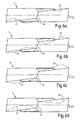
- FIG. 3a shows a side view of a multi-purpose drilling tool 27 with a drill head 28 which carries a cutting element 1 and merges into a drill helix 29. The drill spiral in turn goes over into a clamping shaft 30.
- FIG. 3b is a top view of that in the FIG. 3a shown multi-purpose drilling tool 27 shown.
- the cutting plate 1 defines a nominal diameter DN.
- the clamping surfaces 9, 24 go into flutes 31 and 32 of the drill helix 29 on.
- the Figure 3c shows a detailed view of the in the FIG. 3a shown multi-purpose drilling tool 27.
- the drill head 28 consists of two extensions 33, 34 of the drill helix 29 (see also 3d figure ), which hold the cutting element 1 in the region of side surfaces 16, 17.
- the rake surfaces 9 and 24 are not covered by the extensions 33 and 34 in a lower region 35, which is close to a bottom 22 of the multi-purpose drilling tool 1, and pass directly into the flutes 31 and 32, respectively. As a result, chips and / or cuttings can be conveyed away obstacle-free.
- the 3d figure shows the in the Figure 3c detailed view in a 90 ° rotated view.
- the lateral embedding of the cutting element 1 between webs is again visible, which are formed by the extensions 33, 34.
- FIGS. 4a to 4c is a variant of an insert 1 with shortened transverse cutting edge 14 shown in three views. This is largely carried out analogously to the cutting plates shown in the preceding figures. Compared to the in the FIGS. 2a to 2d The cutting edge 14 shown is shortened. This shortening of the transverse sheath 14 is achieved by a bevel in the region of a drill tip 36.
- the bevel causes a subdivision of a rake surface 9 or 24 in two sub-areas 9a, 9b and 24a, 24b.
- the first partial surfaces 9a, 24a form a much larger area than the second partial surfaces 9b, 24b, which are formed in the region of the drill tip 36.
- the division of the Span surface 9 and 24 in two planar sub-surfaces 9a, 9b and 24a, 24b with different rake angles also causes a polygonal course of the cutting edge 11 and 12. That is, a taper angle ⁇ of the cutting edge 12 to a longitudinal center plane EYZ increases to a drill longitudinal axis. 2 leaps from ⁇ ⁇ 7 ° to ⁇ ⁇ 18 °.
- FIGS. 5a to 5c a further embodiment of a cutting plate 1 is shown in three views. This is carried out largely analogous to the cutting plates shown in the preceding figures, but has no cross-cutting edge, but a tip 37, in which open spaces 10, 13 and clamping surfaces 9, 24 coincide punctiform.
- This tip 37 is achieved by a bevel in the region of a drill tip 36.
- the bevel causes a subdivision of a rake surface 9 or 24 in two sub-areas 9a, 9b and 24a, 24b.
- the first partial surfaces 9a, 24a form a much larger area than the second partial surfaces 9b, 24b, which are formed in the region of the drill tip 36.
- the division of the rake surface 9 or 24 into two planar sub-surfaces 9a, 9b or 24a, 24b with different rake angles ⁇ also causes a polygonal course of the cutting edge 11 or 12. That is, a taper angle ⁇ of the cutting edge 12 to a longitudinal center plane EYZ increases to a drill longitudinal axis 2 jump from ⁇ ⁇ 7 ° to ⁇ ⁇ 23 °.
- FIGS. 6a to 6d show eight embodiments for the course of a cutting edge 11 and 12 in plan view of cutting elements.
- the variants are respectively in figures according to the Figure 2d indicated by dashed lines.
- FIG. 6a shows on a cutting element 1, a cutting edge 11 which is sinusoidal to a transverse Schheide 14, wherein the cutting edge 11 in a radially outer region of the cutting element 1, first of a longitudinal center plane EYZ approaches. Furthermore, the shows FIG. 6a a cutting edge 12, which zigzags toward the transverse cutting edge 14, the cutting edge 12 initially approaching the longitudinal center plane EYZ in a radially outer region of the cutting element 1.
- FIG. 6b shows on a cutting element 1, a cutting edge 11 which runs sinusoidal on a transverse cutting edge 14, wherein the cutting edge 11 in a radially outer region of the cutting element 1 initially removed from a longitudinal center plane EYZ. Furthermore, the shows FIG. 6b a cutting edge 12, which zigzags on the transverse cutting edge 14, wherein the cutting edge 12 in a radially outer region of the cutting element 1 initially removed from the longitudinal center plane EYZ.
- FIG. 6c shows on a cutting element 1, a cutting edge 11 which extends in an arcuate manner on a transverse cutting edge 14, wherein the cutting edge 11 in a radially outer region of the cutting element 1 initially removed from a longitudinal center plane EYZ. Furthermore, the shows FIG. 6c a cutting edge 12 which is similar to an angle on the transverse cutting edge 14, wherein the cutting edge 12 in a radially outer region of the cutting element 1 is initially removed from the longitudinal center plane EYZ.
- FIG. 6d shows on a cutting element 1, a cutting edge 11 which extends in an arcuate manner on a transverse cutting edge 14, wherein the cutting edge 11 in a radially outer region of the cutting element 1 first approximates a longitudinal center plane EYZ. Furthermore, the shows FIG. 6d a cutting edge 12, which extends at an angle to the transverse cutting edge 14, wherein the cutting edge 12 in a radially outer region of the cutting element 1 first approximates the longitudinal center plane EYZ.
- the invention is not limited to illustrated or described embodiments. Rather, it comprises developments of the invention in the context of Patent claims.
- materials for the cutting element are in particular hard metal, PCD or ceramic into consideration.
Applications Claiming Priority (2)
| Application Number | Priority Date | Filing Date | Title |
|---|---|---|---|
| DE10361065A DE10361065A1 (de) | 2003-12-23 | 2003-12-23 | Mehrzweckbohrwerkzeug |
| PCT/EP2004/052932 WO2005063427A1 (de) | 2003-12-23 | 2004-11-12 | Mehrzweckbohrwerkzeug |
Publications (2)
| Publication Number | Publication Date |
|---|---|
| EP1699585A1 EP1699585A1 (de) | 2006-09-13 |
| EP1699585B1 true EP1699585B1 (de) | 2012-01-11 |
Family
ID=34706547
Family Applications (1)
| Application Number | Title | Priority Date | Filing Date |
|---|---|---|---|
| EP04820841A Active EP1699585B1 (de) | 2003-12-23 | 2004-11-12 | Mehrzweckbohrwerkzeug |
Country Status (6)
| Country | Link |
|---|---|
| US (1) | US7401667B2 (ja) |
| EP (1) | EP1699585B1 (ja) |
| JP (1) | JP2007515304A (ja) |
| AT (1) | ATE540770T1 (ja) |
| DE (1) | DE10361065A1 (ja) |
| WO (2) | WO2005061160A1 (ja) |
Families Citing this family (18)
| Publication number | Priority date | Publication date | Assignee | Title |
|---|---|---|---|---|
| DE102006000410A1 (de) * | 2006-08-21 | 2008-02-28 | Hilti Ag | Bohrwerkzeug mit Hartstoffeinsatz |
| DE202007002120U1 (de) * | 2007-02-08 | 2008-06-19 | Illinois Tool Works Inc., Glenview | Gesteinsbohrer |
| US9468980B2 (en) | 2007-04-03 | 2016-10-18 | H. Sam Cho | Contoured PCD and PCBN segments for cutting tools containing such segments |
| US8052765B2 (en) * | 2007-04-03 | 2011-11-08 | Cho H Sam | Contoured PCD and PCBN for twist drill tips and end mills and methods of forming the same |
| DE102010043769B4 (de) * | 2010-11-11 | 2015-07-09 | Hilti Aktiengesellschaft | Ankerbaugruppe, insbesondere für den Berg- und Tunnelbau |
| US9303511B2 (en) | 2013-04-26 | 2016-04-05 | Kennametal Inc. | Flat cutter bit with cutting insert having edge preparation |
| US9347276B2 (en) | 2013-04-26 | 2016-05-24 | Kennametal Inc. | Two prong rotary drill bit with cutting insert having edge preparation |
| US9428968B2 (en) * | 2013-04-26 | 2016-08-30 | Kennametal Inc. | Rotary drill bit with cutting insert having edge preparation |
| USD734790S1 (en) * | 2013-06-12 | 2015-07-21 | Element Six (Production) (Pty) Ltd | Drill bit tip |
| US10441297B2 (en) * | 2015-05-29 | 2019-10-15 | Zimmer, Inc. | Sounder for sizing bone implant |
| US10005137B2 (en) * | 2015-10-22 | 2018-06-26 | Y. G-1 Tool. Co. | Cutting tool |
| US10532412B2 (en) | 2016-09-23 | 2020-01-14 | Milwaukee Electric Tool Corporation | Hole saw arbor assembly |
| EP3354385B1 (en) | 2017-01-06 | 2020-05-27 | Milwaukee Electric Tool Corporation | Hole saw |
| EP3421163A1 (de) * | 2017-06-27 | 2019-01-02 | HILTI Aktiengesellschaft | Bohrer für die meisselnde bearbeitung von gestein |
| USD973733S1 (en) | 2017-08-15 | 2022-12-27 | Milwaukee Electric Tool Corporation | Hole saw |
| US20190076932A1 (en) * | 2017-09-14 | 2019-03-14 | Spirit Aerosystems, Inc. | Apparatus and method for minimizing elongation in drilled holes |
| US11679442B2 (en) | 2018-06-22 | 2023-06-20 | Maestro Logistics, Llc | Drill bit and method for making a drill bit |
| AT522054B1 (de) * | 2019-01-30 | 2020-12-15 | Alpen Maykestag Gmbh | Saugbohrwerkzeug |
Family Cites Families (13)
| Publication number | Priority date | Publication date | Assignee | Title |
|---|---|---|---|---|
| US4222690A (en) * | 1977-12-03 | 1980-09-16 | Ryosuke Hosoi | Drill having cutting edges with the greatest curvature at the central portion thereof |
| DE3123048C2 (de) * | 1981-02-12 | 1983-06-16 | Paul 5630 Remscheid Schmitz | Spiralbohrer |
| JPS60146605U (ja) * | 1984-03-12 | 1985-09-28 | 住友電気工業株式会社 | ドリル構造 |
| JPH02198707A (ja) * | 1989-01-24 | 1990-08-07 | Masao Kubota | ドリル |
| US5172775A (en) * | 1991-03-06 | 1992-12-22 | Kennametal Inc. | Rotary drill bit insert |
| US5918105A (en) * | 1994-12-12 | 1999-06-29 | Black & Decker Inc. | Cutting tools for drilling concrete, aggregate, masonry or the like materials |
| GB9606370D0 (en) * | 1996-03-26 | 1996-06-05 | Dormer Tools Sheffield Ltd | Improvements in or relating to twist drills |
| JPH10291116A (ja) * | 1997-02-18 | 1998-11-04 | Sumitomo Electric Ind Ltd | スローアウェイ式転削工具 |
| DE59710905D1 (de) * | 1997-03-25 | 2003-11-27 | Guehring Joerg | Bohrwerkzeug |
| JP3267215B2 (ja) * | 1997-10-02 | 2002-03-18 | 住友電気工業株式会社 | スローアウェイ式切削工具 |
| AT5577U1 (de) * | 2001-07-02 | 2002-08-26 | Plansee Tizit Ag | Bohrer zum bohren von gestein |
| LU90862B1 (de) * | 2001-12-17 | 2003-06-18 | Cerametal Sarl | Schlag-oder Hammerbohrer |
| SE525336C2 (sv) * | 2002-05-17 | 2005-02-01 | Sandvik Ab | Borrverktyg för hålborrning i metalliska material |
-
2003
- 2003-12-23 DE DE10361065A patent/DE10361065A1/de not_active Withdrawn
-
2004
- 2004-11-03 WO PCT/DE2004/002433 patent/WO2005061160A1/de active Application Filing
- 2004-11-12 AT AT04820841T patent/ATE540770T1/de active
- 2004-11-12 US US10/558,962 patent/US7401667B2/en active Active
- 2004-11-12 EP EP04820841A patent/EP1699585B1/de active Active
- 2004-11-12 WO PCT/EP2004/052932 patent/WO2005063427A1/de active Application Filing
- 2004-11-12 JP JP2006546139A patent/JP2007515304A/ja active Pending
Also Published As
| Publication number | Publication date |
|---|---|
| WO2005063427A1 (de) | 2005-07-14 |
| EP1699585A1 (de) | 2006-09-13 |
| JP2007515304A (ja) | 2007-06-14 |
| US20060243495A1 (en) | 2006-11-02 |
| DE10361065A1 (de) | 2005-07-28 |
| US7401667B2 (en) | 2008-07-22 |
| WO2005061160A1 (de) | 2005-07-07 |
| ATE540770T1 (de) | 2012-01-15 |
Similar Documents
| Publication | Publication Date | Title |
|---|---|---|
| EP1699585B1 (de) | Mehrzweckbohrwerkzeug | |
| DE69819239T2 (de) | Bohrer | |
| DE102009012725B4 (de) | Bohrerspitze sowie Bohrwerkzeug mit einer Bohrerspitze | |
| EP0991489B1 (de) | Spiralbohrer zum trockenbohren | |
| DE60113369T2 (de) | Schneidwerkzeug | |
| EP0692332B1 (de) | Volkeramikbohrer | |
| DE3037097C2 (de) | Vollbohrwerkzeug, insbesondere Spiralbohrer | |
| DE10027544A1 (de) | Bohrerspitze für einen Spiralbohrer und Verfahren zum Herstellen einer Spannut im Bereich einer Bohrerspitze für einen Spiralbohrer | |
| DE10204105A1 (de) | Rundlaufschneidwerkzeug | |
| DE112005000799T5 (de) | Kugelstirnfräser | |
| DE4407119A1 (de) | Gesteinsbohrer | |
| EP1259699B1 (de) | Gesteinsbohrer | |
| DE3407427A1 (de) | Bohrkrone | |
| WO2000025967A1 (de) | Hartmetallschneidplatte für den einsatz an einem bohrer | |
| DE102004022747A1 (de) | Spanwerkzeug mit geometrisch bestimmten Schneiden für Drehantrieb | |
| DE102017216393A1 (de) | Vierschneidiger bohrer | |
| EP2097198B1 (de) | Schneideinsatz, insbesondere für aufbohr- und/oder senkoperationen | |
| WO1998042469A1 (de) | Bohrwerkzeug | |
| EP2845672B1 (de) | Bohrer | |
| DE3803910A1 (de) | Bohrer | |
| DE102017105181B4 (de) | Senkwerkzeug und Verwendung desselben | |
| EP3535080B1 (de) | Bohrwerkzeug | |
| EP0394444A1 (de) | Spiralbohrer zum bohren von tiefen bohrlöchern | |
| DE4323201A1 (de) | Senkwerkzeug | |
| EP1430980B1 (de) | Steinbohrer |
Legal Events
| Date | Code | Title | Description |
|---|---|---|---|
| PUAI | Public reference made under article 153(3) epc to a published international application that has entered the european phase |
Free format text: ORIGINAL CODE: 0009012 |
|
| 17P | Request for examination filed |
Effective date: 20060724 |
|
| AK | Designated contracting states |
Kind code of ref document: A1 Designated state(s): AT BE BG CH CY CZ DE DK EE ES FI FR GB GR HU IE IS IT LI LU MC NL PL PT RO SE SI SK TR |
|
| 17Q | First examination report despatched |
Effective date: 20061218 |
|
| DAX | Request for extension of the european patent (deleted) | ||
| GRAP | Despatch of communication of intention to grant a patent |
Free format text: ORIGINAL CODE: EPIDOSNIGR1 |
|
| GRAS | Grant fee paid |
Free format text: ORIGINAL CODE: EPIDOSNIGR3 |
|
| GRAA | (expected) grant |
Free format text: ORIGINAL CODE: 0009210 |
|
| AK | Designated contracting states |
Kind code of ref document: B1 Designated state(s): AT BE BG CH CY CZ DE DK EE ES FI FR GB GR HU IE IS IT LI LU MC NL PL PT RO SE SI SK TR |
|
| REG | Reference to a national code |
Ref country code: GB Ref legal event code: FG4D Free format text: NOT ENGLISH |
|
| REG | Reference to a national code |
Ref country code: CH Ref legal event code: EP |
|
| REG | Reference to a national code |
Ref country code: AT Ref legal event code: REF Ref document number: 540770 Country of ref document: AT Kind code of ref document: T Effective date: 20120115 |
|
| REG | Reference to a national code |
Ref country code: IE Ref legal event code: FG4D |
|
| REG | Reference to a national code |
Ref country code: DE Ref legal event code: R096 Ref document number: 502004013232 Country of ref document: DE Effective date: 20120308 |
|
| REG | Reference to a national code |
Ref country code: NL Ref legal event code: T3 |
|
| PG25 | Lapsed in a contracting state [announced via postgrant information from national office to epo] |
Ref country code: SI Free format text: LAPSE BECAUSE OF FAILURE TO SUBMIT A TRANSLATION OF THE DESCRIPTION OR TO PAY THE FEE WITHIN THE PRESCRIBED TIME-LIMIT Effective date: 20120111 |
|
| PG25 | Lapsed in a contracting state [announced via postgrant information from national office to epo] |
Ref country code: IS Free format text: LAPSE BECAUSE OF FAILURE TO SUBMIT A TRANSLATION OF THE DESCRIPTION OR TO PAY THE FEE WITHIN THE PRESCRIBED TIME-LIMIT Effective date: 20120511 Ref country code: BG Free format text: LAPSE BECAUSE OF FAILURE TO SUBMIT A TRANSLATION OF THE DESCRIPTION OR TO PAY THE FEE WITHIN THE PRESCRIBED TIME-LIMIT Effective date: 20120411 |
|
| REG | Reference to a national code |
Ref country code: IE Ref legal event code: FD4D |
|
| PG25 | Lapsed in a contracting state [announced via postgrant information from national office to epo] |
Ref country code: PL Free format text: LAPSE BECAUSE OF FAILURE TO SUBMIT A TRANSLATION OF THE DESCRIPTION OR TO PAY THE FEE WITHIN THE PRESCRIBED TIME-LIMIT Effective date: 20120111 Ref country code: FI Free format text: LAPSE BECAUSE OF FAILURE TO SUBMIT A TRANSLATION OF THE DESCRIPTION OR TO PAY THE FEE WITHIN THE PRESCRIBED TIME-LIMIT Effective date: 20120111 Ref country code: PT Free format text: LAPSE BECAUSE OF FAILURE TO SUBMIT A TRANSLATION OF THE DESCRIPTION OR TO PAY THE FEE WITHIN THE PRESCRIBED TIME-LIMIT Effective date: 20120511 Ref country code: GR Free format text: LAPSE BECAUSE OF FAILURE TO SUBMIT A TRANSLATION OF THE DESCRIPTION OR TO PAY THE FEE WITHIN THE PRESCRIBED TIME-LIMIT Effective date: 20120412 |
|
| PG25 | Lapsed in a contracting state [announced via postgrant information from national office to epo] |
Ref country code: CY Free format text: LAPSE BECAUSE OF FAILURE TO SUBMIT A TRANSLATION OF THE DESCRIPTION OR TO PAY THE FEE WITHIN THE PRESCRIBED TIME-LIMIT Effective date: 20120111 |
|
| PG25 | Lapsed in a contracting state [announced via postgrant information from national office to epo] |
Ref country code: DK Free format text: LAPSE BECAUSE OF FAILURE TO SUBMIT A TRANSLATION OF THE DESCRIPTION OR TO PAY THE FEE WITHIN THE PRESCRIBED TIME-LIMIT Effective date: 20120111 Ref country code: EE Free format text: LAPSE BECAUSE OF FAILURE TO SUBMIT A TRANSLATION OF THE DESCRIPTION OR TO PAY THE FEE WITHIN THE PRESCRIBED TIME-LIMIT Effective date: 20120111 Ref country code: IE Free format text: LAPSE BECAUSE OF FAILURE TO SUBMIT A TRANSLATION OF THE DESCRIPTION OR TO PAY THE FEE WITHIN THE PRESCRIBED TIME-LIMIT Effective date: 20120111 Ref country code: SE Free format text: LAPSE BECAUSE OF FAILURE TO SUBMIT A TRANSLATION OF THE DESCRIPTION OR TO PAY THE FEE WITHIN THE PRESCRIBED TIME-LIMIT Effective date: 20120111 Ref country code: CZ Free format text: LAPSE BECAUSE OF FAILURE TO SUBMIT A TRANSLATION OF THE DESCRIPTION OR TO PAY THE FEE WITHIN THE PRESCRIBED TIME-LIMIT Effective date: 20120111 Ref country code: RO Free format text: LAPSE BECAUSE OF FAILURE TO SUBMIT A TRANSLATION OF THE DESCRIPTION OR TO PAY THE FEE WITHIN THE PRESCRIBED TIME-LIMIT Effective date: 20120111 |
|
| PLBE | No opposition filed within time limit |
Free format text: ORIGINAL CODE: 0009261 |
|
| STAA | Information on the status of an ep patent application or granted ep patent |
Free format text: STATUS: NO OPPOSITION FILED WITHIN TIME LIMIT |
|
| PG25 | Lapsed in a contracting state [announced via postgrant information from national office to epo] |
Ref country code: SK Free format text: LAPSE BECAUSE OF FAILURE TO SUBMIT A TRANSLATION OF THE DESCRIPTION OR TO PAY THE FEE WITHIN THE PRESCRIBED TIME-LIMIT Effective date: 20120111 |
|
| 26N | No opposition filed |
Effective date: 20121012 |
|
| REG | Reference to a national code |
Ref country code: DE Ref legal event code: R097 Ref document number: 502004013232 Country of ref document: DE Effective date: 20121012 |
|
| PG25 | Lapsed in a contracting state [announced via postgrant information from national office to epo] |
Ref country code: ES Free format text: LAPSE BECAUSE OF FAILURE TO SUBMIT A TRANSLATION OF THE DESCRIPTION OR TO PAY THE FEE WITHIN THE PRESCRIBED TIME-LIMIT Effective date: 20120422 |
|
| BERE | Be: lapsed |
Owner name: ROBERT BOSCH G.M.B.H. Effective date: 20121130 |
|
| PG25 | Lapsed in a contracting state [announced via postgrant information from national office to epo] |
Ref country code: BE Free format text: LAPSE BECAUSE OF NON-PAYMENT OF DUE FEES Effective date: 20121130 |
|
| REG | Reference to a national code |
Ref country code: AT Ref legal event code: MM01 Ref document number: 540770 Country of ref document: AT Kind code of ref document: T Effective date: 20121130 |
|
| PG25 | Lapsed in a contracting state [announced via postgrant information from national office to epo] |
Ref country code: AT Free format text: LAPSE BECAUSE OF NON-PAYMENT OF DUE FEES Effective date: 20121130 |
|
| PGFP | Annual fee paid to national office [announced via postgrant information from national office to epo] |
Ref country code: CH Payment date: 20131122 Year of fee payment: 10 Ref country code: GB Payment date: 20131122 Year of fee payment: 10 |
|
| PGFP | Annual fee paid to national office [announced via postgrant information from national office to epo] |
Ref country code: IT Payment date: 20131125 Year of fee payment: 10 |
|
| PG25 | Lapsed in a contracting state [announced via postgrant information from national office to epo] |
Ref country code: MC Free format text: LAPSE BECAUSE OF NON-PAYMENT OF DUE FEES Effective date: 20121130 Ref country code: TR Free format text: LAPSE BECAUSE OF FAILURE TO SUBMIT A TRANSLATION OF THE DESCRIPTION OR TO PAY THE FEE WITHIN THE PRESCRIBED TIME-LIMIT Effective date: 20120111 |
|
| PG25 | Lapsed in a contracting state [announced via postgrant information from national office to epo] |
Ref country code: LU Free format text: LAPSE BECAUSE OF NON-PAYMENT OF DUE FEES Effective date: 20121112 |
|
| PG25 | Lapsed in a contracting state [announced via postgrant information from national office to epo] |
Ref country code: HU Free format text: LAPSE BECAUSE OF FAILURE TO SUBMIT A TRANSLATION OF THE DESCRIPTION OR TO PAY THE FEE WITHIN THE PRESCRIBED TIME-LIMIT Effective date: 20041112 |
|
| REG | Reference to a national code |
Ref country code: CH Ref legal event code: PL |
|
| GBPC | Gb: european patent ceased through non-payment of renewal fee |
Effective date: 20141112 |
|
| PG25 | Lapsed in a contracting state [announced via postgrant information from national office to epo] |
Ref country code: LI Free format text: LAPSE BECAUSE OF NON-PAYMENT OF DUE FEES Effective date: 20141130 Ref country code: CH Free format text: LAPSE BECAUSE OF NON-PAYMENT OF DUE FEES Effective date: 20141130 |
|
| PG25 | Lapsed in a contracting state [announced via postgrant information from national office to epo] |
Ref country code: GB Free format text: LAPSE BECAUSE OF NON-PAYMENT OF DUE FEES Effective date: 20141112 |
|
| REG | Reference to a national code |
Ref country code: FR Ref legal event code: PLFP Year of fee payment: 12 |
|
| PG25 | Lapsed in a contracting state [announced via postgrant information from national office to epo] |
Ref country code: IT Free format text: LAPSE BECAUSE OF NON-PAYMENT OF DUE FEES Effective date: 20141112 |
|
| REG | Reference to a national code |
Ref country code: FR Ref legal event code: PLFP Year of fee payment: 13 |
|
| REG | Reference to a national code |
Ref country code: FR Ref legal event code: PLFP Year of fee payment: 14 |
|
| PGFP | Annual fee paid to national office [announced via postgrant information from national office to epo] |
Ref country code: NL Payment date: 20181122 Year of fee payment: 15 |
|
| REG | Reference to a national code |
Ref country code: NL Ref legal event code: MM Effective date: 20191201 |
|
| PG25 | Lapsed in a contracting state [announced via postgrant information from national office to epo] |
Ref country code: NL Free format text: LAPSE BECAUSE OF NON-PAYMENT OF DUE FEES Effective date: 20191201 |
|
| PGFP | Annual fee paid to national office [announced via postgrant information from national office to epo] |
Ref country code: FR Payment date: 20231123 Year of fee payment: 20 |
|
| PGFP | Annual fee paid to national office [announced via postgrant information from national office to epo] |
Ref country code: DE Payment date: 20240123 Year of fee payment: 20 |