EP3354385B1 - Hole saw - Google Patents
Hole saw Download PDFInfo
- Publication number
- EP3354385B1 EP3354385B1 EP18150515.7A EP18150515A EP3354385B1 EP 3354385 B1 EP3354385 B1 EP 3354385B1 EP 18150515 A EP18150515 A EP 18150515A EP 3354385 B1 EP3354385 B1 EP 3354385B1
- Authority
- EP
- European Patent Office
- Prior art keywords
- sidewall
- hole saw
- gullet
- inches
- meters
- Prior art date
- Legal status (The legal status is an assumption and is not a legal conclusion. Google has not performed a legal analysis and makes no representation as to the accuracy of the status listed.)
- Active
Links
Images


Classifications
-
- B—PERFORMING OPERATIONS; TRANSPORTING
- B23—MACHINE TOOLS; METAL-WORKING NOT OTHERWISE PROVIDED FOR
- B23B—TURNING; BORING
- B23B51/00—Tools for drilling machines
- B23B51/04—Drills for trepanning
- B23B51/0426—Drills for trepanning with centering devices
-
- B—PERFORMING OPERATIONS; TRANSPORTING
- B23—MACHINE TOOLS; METAL-WORKING NOT OTHERWISE PROVIDED FOR
- B23B—TURNING; BORING
- B23B51/00—Tools for drilling machines
- B23B51/04—Drills for trepanning
- B23B51/0466—Drills for trepanning with exchangeable cutting inserts, e.g. able to be clamped
-
- B—PERFORMING OPERATIONS; TRANSPORTING
- B23—MACHINE TOOLS; METAL-WORKING NOT OTHERWISE PROVIDED FOR
- B23B—TURNING; BORING
- B23B2260/00—Details of constructional elements
- B23B2260/072—Grooves
-
- Y—GENERAL TAGGING OF NEW TECHNOLOGICAL DEVELOPMENTS; GENERAL TAGGING OF CROSS-SECTIONAL TECHNOLOGIES SPANNING OVER SEVERAL SECTIONS OF THE IPC; TECHNICAL SUBJECTS COVERED BY FORMER USPC CROSS-REFERENCE ART COLLECTIONS [XRACs] AND DIGESTS
- Y10—TECHNICAL SUBJECTS COVERED BY FORMER USPC
- Y10T—TECHNICAL SUBJECTS COVERED BY FORMER US CLASSIFICATION
- Y10T408/00—Cutting by use of rotating axially moving tool
- Y10T408/89—Tool or Tool with support
- Y10T408/895—Having axial, core-receiving central portion
Definitions
- the present invention relates to hole saws according to the preamble of claim 1, and more particularly to gullets formed in the hole saws.
- Such hole saws are known from US-A-2014/023447 .
- US-A-2014/023447 describes a cutting tool including a generally cylindrical body, a plurality of cutting teeth formed on the generally cylindrical body, a plurality of non-cutting protrusions formed on the generally cylindrical body, and a plurality of gullets formed on the generally cylindrical body.
- Each gullet is formed between one of the plurality of cutting teeth and one of the plurality of non-cutting protrusions.
- Each gullet has a base and a gullet depth measured from the base to a tip of a corresponding cutting tooth.
- Each non-cutting protrusion is located approximately halfway between the tips of two adjacent cutting teeth and has a height that is at most about 75% of the gullet depth.
- DE-U-202004003900 describes a centering drilling unit.
- FR-A-2302808 describes a tubular drilling bit with several independent cutting blades for cutting large diameter holes and permitting core recovery. The open working end of the bit is subdivided into longitudinal blades by several helical slots, with cutting edges mounted on the free blade extremities. This arrangement obtains flexible cutters less liable to impact fractures.
- the distance that the slots deviate for a line parallel to the bit axis is equal to the blade width, and the pitch of the helix equals blade height times 360 degrees divided by the angle subtended by each blade and the bit axis.
- Successive cutting edges may be staggered relative to each other in the circumferential sense, and cutting edges may be monolithic with the blade, or be welded appendages.
- a hole saw is movable about a rotational axis in a cutting direction to cut into a workpiece.
- the hole saw includes a cylindrical body having a sidewall with a first end and a second end opposite the first end.
- the cylindrical body also includes a gullet formed in the sidewall between a leading surface, a trailing surface, and a bottom surface of the sidewall.
- the trailing surface defines a portion having a first radius.
- the bottom surface has a second radius. The first radius is larger than the second radius.
- the hole saw also includes a cutting tooth coupled to the first end of the sidewall adj acent the gullet.
- a first portion of the trailing surface extending between the cutting tooth and the curved portion is a substantially linear surface.
- the gullet may define a central longitudinal axis extending between the first and second ends of the sidewall.
- the central longitudinal axis may be obliquely oriented relative to the rotational axis such that the gullet is angled from the first end to the bottom surface in a direction toward the cutting direction.
- the central longitudinal axis may be oriented at an angle between about 5 degress and about 15 degrees relative to the rotational axis.
- a ratio of the first radius to the second radius may be between about 2.5 and about 5.
- the first radius may be between about 0.0254 meters (1 inch) and about 0.03175meters (1.25 inches).
- the second radius may be between about 0.00635meters (0.25 inches) and about 0.1016meters (0.4 inches).
- the sidewall may include a support surface in the leading surface that faces the first end. The support surface may be configured to support a tool to leverage material out of the cylindrical body.
- the support surface may be a first support surface.
- the sidewall may include a second support surface in the leading surface that faces the first end. The second support surface may be configured to support the tool to leverage material of the cylindrical body.
- the cylindrical body may include two gullets.
- the sidewall may define an aperture positioned between the two gullets. The aperture may be configured to receive a tool to leverage material out of the cylindrical body.
- the cylindrical body may include less than three gullets.
- the cylindrical body may define a maximum diameter equal to or less than about 0.05715meters (2.25 inches).
- the gullet may extend through the first end of the sidewall.
- a distance between the leading surface and a tip of the cutting tooth in a direction perpendicular to the rotational axis may be between about 0.0127meters (0.5 inches) and about 0.01778meters (0.7 inches).
- a dimension parallel to the rational axis may be defined between the first end of the sidewall and the bottom surface of the gullet. The dimension may be greater than 0.0381meters (1.5 inches).
- the cylindrical body may be made of a first material.
- the cutting tool may be made of a second material different than the first material.
- the cutting tooth may be fixedly attached to the sidewall adjacent the trailing surface.
- the cutting tooth may be a carbide cutting tooth.
- the cutting tooth may include a rake surface.
- the rake surface may be oriented at a positive rake angle.
- the cylindrical body may include an end cap coupled to the second end of the sidewall. The end cap may be configured to allow for a power tool to be coupled to the hole saw.
- the gullet defines a central longitudinal axis extending between the first and second ends of the sidewall that is obliquely oriented relative to the rotational axis such that the gullet is angled from the first end to the bottom surface in a direction toward the cutting direction.
- the gullet has a dimension measured parallel to the rotational axis between the first end of the sidewall and the bottom surface of the gullet that is greater than 0.0381meters (1.5 inches).
- the central longitudinal axis may be oriented at an angle between about 1 degree and about 40 degrees relative to the rotational axis.
- the central longitudinal axis may be oriented at an angle between about 5 degrees and about 15 degrees relative to the rotational axis.
- the dimension may be greater than 0.0762meters (3 inches).
- the dimension may be between 0.0381meters (1.5 inches) and about 0.0508meters (2.0 inches).
- the gullet extends through the first end of the sidewall and defines a central longitudinal axis extending between the first and second ends of the sidewall.
- the central longitudinal axis is obliquely oriented relative to the rotational axis such that the gullet is angled from the first end to the bottom surface in a direction toward the cutting direction.
- a dimension measured between the leading surface and a tip of the cutting tooth in a direction perpendicular to the rotational axis is between about 0.0127meters (0.5 inches) and about 0.1778meters (0.7 inches).
- the central longitudinal axis may be oriented at an angle between about 1 degree and about 40 degrees relative to the rotational axis.
- the central longitudinal axis may be oriented at an angle between about 5 degrees and about 15 degrees relative to the rotational axis.
- the gullet extends through the first end of the sidewall and defines a central longitudinal axis extending between the first and second ends of the sidewall.
- the central longitudinal axis is obliquely oriented relative to the rotational axis such that the gullet is angled from the first end to the bottom surface in a direction toward the cutting direction.
- the gullet has a first dimension measured parallel to the rotational axis between the first end of the sidewall and the bottom surface of the gullet that is greater than 0.0381 meters (1.5 inches).
- a second dimension measured perpendicular to the rotational axis between the leading surface and a tip of the cutting tooth is between about 0.0127 meters (0.5 inches) and about 0.01778 meters (0.7 inches).
- the cutting tooth may be a carbide cutting tooth secured to the first end of the sidewall.
- the cylindrical body may include an end cap coupled to the second end of the sidewall. The end cap may be configured to allow for a power tool to be coupled to the hole saw.
- the terms “mounted,” “connected,” “supported,” and “coupled” and variations thereof are used broadly and encompass both direct and indirect mountings, connections, supports, and couplings. Further, “connected” and “coupled” are not restricted to physical or mechanical connections or couplings. Terms of degree, such as “about,” “substantially,” or “approximately” are understood by those of ordinary skill to refer to reasonable ranges outside of the given value, for example, general tolerances associated with manufacturing, assembly, and use of the described embodiments.
- FIGS. 1-5 illustrate a hole saw 100 including a cylindrical body 105 defining a cavity 110.
- the cylindrical body 105 includes a sidewall 115 having a first end 120 and a second end 125 with the second end 125 positioned opposite the first end 120.
- the hole saw 100 also includes an end cap 130 coupled to the second end 125 and has an aperture 135 sized to receive an arbor 140 such that the hole saw 100 can be coupled to and driven by a tool 145 (e.g., a power drill or the like) via the arbor 140.
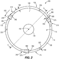
- the tool 145 drives the hole saw 100 about a rotational axis 150 in a cutting direction 155 ( FIG. 2 ).
- the arbor 140 is selectively coupled to the end cap 130, but in other embodiments, the arbor 140 can be fixedly coupled to the end cap 130.
- a pilot drill bit 156 e.g., a twist drill bit, a spade drill bit, etc.
- the illustrated cylindrical body 105 is made of a metallic material (e.g., low carbon steel, etc.). In other embodiments, the cylindrical body 105 can be made of a different metallic material (e.g., high carbon steel, etc.).
- the sidewall 115 defines a maximum outer diameter 160.
- the outer diameter 160 can be between about 0.0254 meters (1 inch) and about 0.1778 meters (7 inches). In some embodiments, the outer diameter 160 can be about 0.034798 meters (1.37 inches), about 0.065024 meters (2.56 inches), about 0.1016 meters (4 inches), or about 0.15875 meters (6.25 inches). In further embodiments, the outer diameter 160 can be greater than 0.1778 meters (7 inches).
- the sidewall 115 also defines a maximum thickness 165. The thickness 165 can be between about 0.001778 meters (0.07 inches) and about 0.002794 meters (0.11 inches).
- the thickness 165 can be about 0.002032 meters (0.08 inches), about 0.002286 meters (0.09 inches), about 0.00254 meters (0.1 inches), or about 0.0026416 meters (0.104 inches).
- the sidewall 115 further defines a sidewall height or dimension 170 extending between the first end 120 and the second end 125 in a direction parallel to the rotational axis 150.
- the illustrated sidewall height 170 is between about 0.0635 meters (2.5 inches) and about 0.0762 meters (3 inches). In other embodiments, the sidewall height 170 can be between about 0.0381 meters (1.5 inches) and about 0.127 meters (5 inches).
- the sidewall 115 includes three gullets 175 equally spaced about the rotational axis 150 (e.g., each gullet 175 is spaced about 120 degrees relative to an adjacent gullet 175).
- the hole saw 100 can include more than three gullets 175 (e.g., four, five, six, etc.) or can include less than three gullets (e.g., two or one) with the gullets 175 equally or non-equally spaced about the rotational axis 150.
- the hole saw 100 can include two gullets 175 (spaced 180 degrees apart) when the outer diameter 160 is less than about 0.05715 meters (2.25 inches).
- each gullet 175 defines a central longitudinal axis 180 extending between the first end 120 and the second end 125.
- Each gullet 175 includes an open end 185 adjacent the first end 120 and is defined by a bottom surface 190 of the sidewall 115 opposite the open end 185, a leading surface 195 of the sidewall 115 extending between the open end 185 and the bottom surface 190, and a trailing surface 200 of the sidewall 115 extending between the open end 185 and the bottom surface 190.
- each trailing surface 200 includes a seat or notch 205 formed adjacent the open end 185 and a trailing surface portion 210 positioned between the notch 205 and the bottom surface 190 in a direction parallel to the rotational axis 150.
- a first portion 215 of each trailing surface 200 extends between the notch 205 and the trailing surface portion 210 and a second portion 220 of each trailing surface 200 extends between the trailing surface portion 210 and the bottom surface 190.
- an edge 225 is positioned between the leading surface 195 and the first end 120 that defines a substantially 90 degree edge. In other embodiments, the edge 225 can be a curved edge.
- all three gullets 175 include the substantially same geometry, but in other embodiments, two or more gullets 175 can include different geometries.
- One of the gullets 175 will be described in detail below but can be applicable to one or more of the remaining gullets 175.
- the illustrated first portion 215 of the trailing surface 200 is a substantially linear surface oriented substantially parallel to the rotational axis 150.
- the central longitudinal axis 180 of the gullet 175 is parallel to the rotational axis 150 so that the first portion 215 is also parallel to the central longitudinal axis 180.
- the illustrated trailing surface portion 210 defines a first radius 230 between about 0.0254 meters (1 inch) and about 0.03175 meters (1.25 inches).
- the first radius 230 can be between about 0.03175 meters (1.25 inches) and about 2 inches or the first radius 230 can be between about 0.01016 meters (0.4 inches) and about 0.0254 meters (1 inch).
- the trailing surface portion 210 is formed in a lower half of the gullet 175 in a direction parallel to the rotational axis 150.
- the illustrated second portion 220 of the trailing surface 200 is a substantially linear surface, but in other embodiments, the second portion 220 can be a curved surface.
- the second portion 220 is also oriented at an oblique angle 235 relative to the rotational axis 150.
- the illustrated oblique angle 235 is between about 40 degrees and about 50 degrees.
- the oblique angle 235 can be between about 50 degrees and about 70 degrees or the oblique angle 235 can be between about 20 degrees and about 40 degrees.
- a first angle 240 is defined between the first portion 215 and the second portion 220. The illustrated first angle 240 is between about 130 degrees and about 140 degrees. In other embodiments, the first angle 240 can be between 140 degrees and about 170 degrees, or the first angle 240 can be between about 80 degrees and about 130 degrees.
- the illustrated bottom surface 190 defines a second radius 245 between about 0.00635 meters (0.25 inches) and about 0.01016 (0.4 inches).
- the second radius 245 can be between about 0.01016 meters (0.4 inches) and about 0.0254 meters (1 inch), or the second radius 245 can be between about 0.00254 meters (0.1 inches) and about 0.00635 meters (0.25 inches). In some embodiments, the second radius 245 can be equal to or less than the first radius 230.
- a ratio of the first radius 230 to the second radius 245 is between about 2.5 to about 5. In other embodiments, the ratio of the first radius 230 to the second radius 245 is between about 1 and about 6. In further embodiments, the ratio of the first radius 230 to the second radius 245 is between about 3 and about 4.
- the illustrated leading surface 195 is a substantially linear surface oriented substantially parallel to the rotational axis 150.
- a second angle 250 is defined between the second portion 220 and the leading surface 195.
- the illustrated second angle 250 is between about 40 degrees and about 50 degrees. In other embodiments, the second angle 250 can be between 50 degrees and about 80 degrees or the second angle 250 can be between about 10 degrees and about 40 degrees.
- the gullet 175 defines a gullet height or dimension 255 extending between the first end 120 and the bottom surface 190 in a direction parallel to the rotational axis 150.
- the illustrated gullet height 255 is greater than about 0.0381 meters (1.5 inches).
- the gullet height 255 can be between about 0.04318 meters (1.7 inches) and about 0.04826 meters (1.9 inches), or the gullet height 255 can be between about 0.04826 meters (1.9 inches) and about 0.0762 meters (3 inches).
- a ratio of the sidewall height 170 over the gullet height 255 is about 1.4.
- the ratio of the sidewall height 170 over the gullet height 255 can be between about 1.1 and about 2. In further embodiments, the ratio of the sidewall height 170 over the gullet height 255 can be between about 2 and about 4.
- the illustrated sidewall 115 also defines a height 260 extending between the bottom surface 190 of each gullet 175 and the second end 125 of the sidewall 115.
- the height 260 is between about 0.01778 meters (0.7 inches) and about 0.02286 meters (0.9 inches). In other embodiments, the height 260 can be between about 0.02286 meters (0.9 inches) and about 0.0381 meters (1.5 inches) or the height 260 can be between about 0.00254 meters (0.1 inches) and about 0.01778 meters (0.7 inches).
- the gullet 175 also defines a maximum gullet width 265 extending between the leading surface 195 and the trailing surface 200 in a direction perpendicular to the rotational axis 150.
- the maximum gullet width 265 extends between the leading surface 195 and a point 270 located on the first portion 215 directly below the notch 205.
- the illustrated maximum gullet width 265 is between about 0.01905 meters (0.75 inches) and about 0.03048 meters (1.2 inches). In other embodiments, the maximum gullet width 265 can be between about 0.03048 meters (1.2 inches) and about 0.0381 meters (1.5 inches), or the maximum gullet width 265 can be between about 0.01016 meters (0.4 inches) and about 0.01905 meters (0.75 inches).
- the hole saw 100 also includes cutting teeth 275 positioned adjacent the first end 120 of the sidewall 115.
- Each cutting tooth 275 has a cutting tip 280 positioned beyond the first end 120 (i.e., above the first end 120 as illustrated in FIG. 4 ).
- the cutting teeth 275 are carbide cutting teeth that are seated within the notches 205 of the sidewall 115 and secured to the sidewall 115 (e.g., by a brazing operation or the like).
- the carbide cutting teeth 275 include a material hardness that is greater than a material hardness of the sidewall 115.
- the cutting teeth 275 can be made of a different material (e.g., hardened steel, etc.).
- each cutting tooth 275 includes a rake surface 285 and a relief surface 290 with each rake surface 285 facing into one of the gullets 175.
- Each rake surface 285 defines a positive rake angle 295 (e.g., angled toward the cutting direction 155) relative to the rotational axis 150 between about 5 degrees and about 15 degrees.
- a minimum gullet width 296 between each cutting tip 280 and the corresponding leading surface 195 perpendicular to the rotational axis 150 is between about 0.0127 meters (0.5 inches) and about 0.01778 meters (0.7 inches).
- the minimum gullet width 296 can be between about 0.01778 meters (0.7 inches) and about 0.03048 meters (1.2 inches). In further embodiments, the minimum gullet width 296 can be greater than the maximum gullet width 265. In yet further embodiments, the rake angle 295 can be a negative rake angle (e.g., angled away from the cutting direction 155). A tooth angle 300 is defined between the rake surface 285 and the relief surface 290 between about 60 degrees and about 70 degrees ( FIG. 4 ). As best shown in FIG. 2 , each cutting tip 280 defines a tip width 305 between about 0.00254 meters (0.1 inches) and about 0.00508 meters (0.2 inches).
- each cutting tooth 275 is greater than the thickness 165 of the sidewall 115. As such, a total cutting diameter of the hole saw 100 is greater than the maximum outer diameter 160 of the sidewall 115. In other embodiments, the tip width 305 can be substantially the same as the thickness 165 of the sidewall 115 with the cutting teeth 275 bent radially inward or outward relative to the rotational axis 150.
- a recess or relief 310 is formed within the first end 120 of the sidewall 115 directly behind each cutting tooth 275 with a trailing portion 315 of each recess 310 angled in a direction away from the cutting direction 155.
- Each recess 310 defines a recess angle 320 relative to the rake surface 285 that is less than the tooth angle 300.
- the recesses 310 provide enough clearance for a grinding wheel or the like to shape the cutting teeth 275 without contacting the sidewall 115.
- each gullet 175 defines an area 325 between the rake surface 285, the trailing surface 200, the bottom surface 190, and the leading surface 195.
- the area 325 of each gullet 175 is equal to or greater than 0.0007742 meters squared (1.2 inches squared). In other embodiments, the area 325 of each gullet 175 is between about 0.0007742 meters squared (1.2 inches squared) and about 0.00225806 meters squared (3.5 inches squared). In further embodiments, the area 325 of each gullet 175 is between about 0.0007742 meters squared (1.2 inches squared) and about 0.00129032 meters squared (2 inches squared).
- the total area of the illustrated gullets 175 is equal to or greater than 0.00232258 meters squared (3.6 inches squared).
- Each gullet 175 also defines a volume, which is determined by multiplying the area 325 of each gullet 175 by the maximum thickness 165 of the sidewall 115. As such, the volume of each gullet 175 is equal to or greater than 1.3765 x 10 -6 meters cubed (0.084 inches cubed).
- a ratio of the tip width 305 over the volume of one of the gullets 175 is about 0.2. In other embodiments, the ratio of the tip width 305 over the volume of one of the gullets 175 can be between about 0.1 and about 1.1.
- the hole saw 100 is operable to cut into a workpiece 330 that defines a workpiece height 335.
- the workpiece height 335 is about - 0.0381 meters (1.5 inches) (e.g., height of a standard 2 by 4 piece of lumber). In other embodiments, the workpiece height 335 can be less than 0.0381 meters (1.5 inches).
- the cutting teeth 275 cut into the workpiece 330, thereby forming workpiece chips that collect within the gullets 175.
- the illustrated gullets 175 include a particular volume to accommodate the workpiece chips as the hole saw 100 cuts into the workpiece 330.
- the volume of the gullets 175 is not sufficient to accommodate the workpiece chips, the workpiece chips will build up within the gullets 175 and decrease the efficiency of the hole saw 100 cutting into the workpiece 330.
- a cylindrical workpiece plug will be removed from the cavity 110 of the hole saw 100.
- a user can grip the cylindrical workpiece plug (via their fingers) through the gullets 175 to axially slide the cylindrical workpiece plug along the rotational axis and out of the cavity 110.
- the minimum gullet width 296 of each gullet 175 is sized to provide enough clearance between each cutting tip 280 and the corresponding leading surface 195 so that a user's finger avoids contact with the cutting tip 280 as the cylindrical workpiece plug is removed from the hole saw 100.
- FIG. 6 illustrates a planar view of a portion of a hole saw 400 according to another embodiment.
- the hole saw 400 is similar to the hole saw 100 of FIGS. 1-5 ; therefore, similar components are designated with similar references numbers plus 300. At least some differences and/or at least some similarities between the hole saws 100, 400 will be discussed in detail below.
- components or features described with respect to one or some of the embodiments described herein are equally applicable to any other embodiments described herein within the scope of the claims and can include similar reference numbers.
- the illustrated hole saw 400 is moveable about a rotational axis 450 in a cutting direction 455 and includes a sidewall 415 having a first end 420 and a second end 425.
- the sidewall 415 also includes gullets 475 (only one gullet 475 is illustrated in FIG. 6 ) each defining a central longitudinal axis 480.
- Each gullet 475 includes a notch 505, an open end 485, a bottom surface 490 defining a second radius 545, a leading surface 495, and a trailing surface 500.
- Each trailing surface 500 includes a trailing surface portion 510 defining a first radius 530, a first portion 515, and a second portion 520 with the trailing surface portion 510 positioned between the first portion 515 and the second portion 520.
- each first portion 515 is parallel to the leading surface 495; however, in other embodiments, the first portion 515 can be obliquely angled relative to the leading surface 495.
- the first portion 515 of each trailing surface 500 is oriented at a third angle 640 between about 5 degrees and about 15 degrees relative to the rotational axis 450 so that the first portion 515 is angled from the first end 420 to the second end 425 in a direction toward the cutting direction 455.
- each central longitudinal axis 480 is also oriented between about 5 degrees and about 15 degrees relative to the rotational axis 450 so that the central longitudinal axis 480 is angled from the first end 420 to the second end 425 in a direction toward the cutting direction 455.
- the third angle 640 is greater than about 5 degrees.
- the third angle 640 is less than about 15 degrees.
- the third angle 640 is between about 1 degree and about 40 degrees.
- the hole saw 400 also includes cutting teeth 575 (only one cutting tooth 575 is illustrated in FIG. 6 ) each having a cutting tip 580 and seated within one notch 505.
- Each cutting tooth 575 includes a rake surface 585 and a relief surface 590.
- FIG. 7 illustrates a planar view of a portion of a hole saw 700 according to another embodiment.
- the hole saw 700 is similar to the hole saw 100 of FIGS. 1-5 ; therefore, similar components are designated with similar references numbers plus 600. At least some differences and/or at least some similarities between the hole saws 100, 700 will be discussed in detail below.
- components or features described with respect to one or some of the embodiments described herein are equally applicable to any other embodiments described herein within the scope of the claims and can include similar reference numbers.
- the illustrated hole saw 700 is moveable about a rotational axis 750 in a cutting direction 755 and includes a sidewall 715 having a first end 720 and a second end 725.
- the sidewall 715 also includes gullets 775 (only one gullet 775 is illustrated in FIG. 7 ) each defining a central longitudinal axis 780.
- Each gullet 775 includes a notch 805, an open end 785, a bottom surface 790 defining a second radius 845, a leading surface 795, and a trailing surface 800.
- Each trailing surface 800 includes a trailing surface portion 810 defining a first radius 830, a first portion 815, and a second portion 820 with the trailing surface portion 810 positioned between the first portion 815 and the second portion 820.
- Each leading surface 795 includes a third portion 945, a fourth portion 950, and a support surface 955 positioned between the third portion 945 and the fourth portion 950 in a direction parallel to the rotational axis 750.
- the support surface 955 is also positioned at a support surface distance 960 between about 0.01778 meters (0.7 inches) and about 0.0254 meters (1 inch) from the first end 720 of the sidewall 715. In other embodiments, the support surface 955 can be formed within at least one of the gullets 775.
- the third portion 945 is oriented parallel to the fourth portion 950 of each leading surface 795 and the first portion 815 of each trailing surface 800.
- Each third portion 945 and fourth portion 950 are also offset (e.g., nonlinear) relative to each other. In other embodiments, the third portion 945 can be obliquely angled relative to the first portion 815 and/or the fourth portion 950.
- Each support surface 955 is oriented at a support angle 965 relative to the rotational axis 750. The support angle 965 is less than 90 degrees relative to the rotational axis 750 so that the support surface 955 is angled downwardly and toward the cutting direction 755 (e.g., the support surface 955 generally faces upwardly toward the first end 720).
- each support angle 965 can be less than 90 degrees and greater than 75 degrees relative to the rotational axis 750.
- each support surface 955 is positioned above the trailing surface portion 810 in a direction parallel to the rotational axis 750. In other embodiments, each support surface 955 can be positioned at the same height of the trailing surface portion 810 or positioned below the trailing surface portion 810.
- the hole saw 700 also includes cutting teeth 875 (only one cutting tooth 875 is illustrated in FIG. 7 ) each having a cutting tip 880 and seated within one notch 805.
- Each cutting tooth 875 includes a rake surface 885 and a relief surface 890.
- a cylindrical workpiece plug can be removed from the hole saw 700 by using a tool (e.g., a screwdriver or the like).
- the tool is inserted within one of the gullets 775 below the cylindrical workpiece plug.
- the tool engages the bottom surface 790 of the gullet 775 to leverage and push the cylindrical workpiece plug out of the first end 720.
- the tool can also engage the support surface 955 to leverage and push the cylindrical workpiece plug out of the first end 720.
- the support surface 955 is angled downwardly and toward the cutting direction 755
- the tool can be captured on the support surface 955 without sliding into the gullet 775 as the tool is used to leverage the cylindrical workpiece plug out of the hole saw 700.
- FIG. 8 illustrates a planar view of a portion of a hole saw 1000 according to another embodiment.
- the hole saw 1000 is similar to the hole saw 100 of FIGS. 1-5 ; therefore, similar components are designated with similar references numbers plus 900. At least some differences and/or at least some similarities between the hole saws 100, 1000 will be discussed in detail below.
- components or features described with respect to only one or some of the embodiments described herein are equally applicable to any other embodiments described herein within the scope of the claims and can include similar reference numbers.
- the illustrated hole saw 1000 is moveable about a rotational axis 1050 in a cutting direction 1055 and includes a sidewall 1015 having a first end 1020 and a second end 1025.
- the sidewall 1015 also includes gullets 1075 (only one gullet 1075 is illustrated in FIG. 8 ) each defining a central longitudinal axis 1080.
- Each gullet 1075 includes a notch 1105, an open end 1085, a bottom surface 1090 defining a second radius 1145, a leading surface 1095, and a trailing surface 1100.
- Each trailing surface 1100 includes a trailing surface portion 1110 defining a first radius 1130, a first portion 1115, and a second portion 1120 with the trailing surface portion 1110 positioned between the first portion 1115 and the second portion 1120.
- Each leading surface 1095 includes a third portion 1245, a fourth portion 1250, and a support surface 1255 (similar to the support surface 955 of FIG. 7 ) formed on a protrusion 1270 of the sidewall 1015, which extends into each gullet 1075.
- the illustrated third portion 1245 and fourth portion 1250 are substantially collinear surfaces with the support surface 1255 oriented at a substantially 90 degree angle relative to the rotational axis 1050.
- the hole saw 1000 also includes cutting teeth 1175 (only one cutting tooth 1175 is illustrated in FIG. 8 ) each having a cutting tip 1180 and seated within one notch 1105.
- Each cutting tooth 1175 includes a rake surface 1185 and a relief surface 1190.
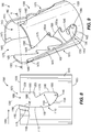
- FIGS. 9-11 illustrate a hole saw 1300 according to another embodiment.
- the hole saw 1300 is similar to the hole saw 100 of FIGS. 1-5 ; therefore, similar components are designated with similar references numbers plus 1200. At least some differences and/or at least some similarities between the hole saws 100, 1300 will be discussed in detail below.
- components or features described with respect to one or some of the embodiments described herein are equally applicable to any other embodiments described herein within the scope of the claims and can include similar reference numbers.
- the illustrated hole saw 1300 is moveable about a rotational axis 1350 in a cutting direction 1355 and includes a cylindrical body 1305 having a sidewall 1315 that defines a cavity 1310 and an end cap 1330 having an aperture 1335.
- the sidewall 1315 includes a first end 1320 and a second end 1325.
- the sidewall 1315 defines a maximum outer diameter 1360 ( FIG. 11 ), a maximum thickness 1365 ( FIG. 11 ), and a sidewall height or dimension 1370 ( FIG. 10 ) extending between the first end 1320 and the second end 1325 in a direction parallel to the rotational axis 1350.
- the sidewall height 1370 can be between about 0.08382 meters (3.3 inches) and about 0.09398 meters (3.7 inches).
- the sidewall height 1370 can be between about 0.09398 meters (3.7 inches) and about 0.1143 meters (4.5 inches).
- the sidewall 1315 also includes gullets 1375 each defining a central longitudinal axis 1380 oriented at an oblique angle (e.g., between about 5 degrees and about 15 degrees) relative to the rotational axis 1350.
- Each gullet 1375 includes a notch 1405, an open end 1385, a bottom surface 1390 defining a second radius 1445, a leading surface 1395, and a trailing surface 1400.
- Each trailing surface 1400 includes a trailing surface portion 1410 defining a first radius 1430, a first portion 1415, and a second portion 1420 with the trailing surface portion 1410 positioned between the first portion 1415 and the second portion 1420.
- Each leading surface 1395 includes an edge 1425 and two support surfaces 1555a, 1555b (similar to the support surfaces 955, 1255 illustrated in FIGS. 7 and 8 ) so that each leading surface 1395 includes a third portion 1545, a fourth portion 1550, and a fifth portion 1575. With the two support surfaces 1555a, 1555b formed in the leading surface 1395, the leading surface 1395 defines a zig-zag shaped surface.
- the illustrated third portion 1545, fourth portion 1550, and fifth portion 1575 are all linear surfaces with the third portion 1545 obliquely oriented relative to the fourth portion 1550 and the fourth portion 1550 oriented substantially parallel to the fifth portion 1575.
- two or more of the third portion 1545, the fourth portion 1550, and the fifth portion 1575 can be substantially parallel relative to each other or obliquely oriented relative to each other.
- at least one of the third portion 1545, the fourth portion 1550, and the fifth portion 1575 can be a curved surface.
- the third portion 1545, the fourth portion 1550, the fifth portion 1575, and the two support surface 1555a, 1555b can be omitted so that the leading surface 1395 is one linear surface.
- the illustrated first support surface 1555a is positioned from the first end 1320 at a first support distance 1560a of between about 0.0508 meters (2 inches) and about 0.05588 meters (2.2 inches).
- the second support surface 1555b is positioned from the first end 1320 at a second support distance 1560b of between about 0.0254 meters (1 inch) and about 0.0381 meters (1.5 inches).
- each leading surface 1395 can include one support surface.
- each leading surface 1395 can include more than two support surfaces.
- each gullet 1375 defines an oblique angle 1435 between the second portion 1420 and the rotational axis 1350.
- the oblique angle 1435 is between about 55 degrees and about 65 degrees.
- the oblique angle 1435 is defined between the rotational axis 1350 and a tangent line extending through a midpoint of the second portion 1420.
- a first angle 1440 is defined between the first portion 1415 and the second portion 1420 that is between about 120 degrees and about 135 degrees.
- the first angle 1440 is defined between the first portion 1415 and a tangent line extending through a midpoint of the second portion 1420.
- a second angle 1450 is defined between the second portion 1420 and the third portion 1545 that is between about 35 degrees and about 45 degrees.
- the second angle 1450 is defined between the third portion 1545 and a tangent line extending through a midpoint of the second portion 1420.
- the second angle 1450 is defined between tangent lines extending through midpoints of the second and third portions 1420, 1545.
- each gullet 1375 defines a gullet height or dimension 1455 extending between the first end 1320 and the bottom surface 1390 in a direction parallel to the rotational axis 1350.
- the illustrated gullet height 1455 is between about 0.0762 meters (3 inches) and about 0.08128 meters (3.2 inches). In other embodiments, the gullet height 1455 can be between about 0.08128 meters (3.2 inches) and about 0.1016 meters (4 inches), or the gullet height 1455 can be between about 0.0635 meters (2.5 inches) and about 0.0762 meters (3 inches).
- a ratio of the sidewall height 1370 over the gullet height 1455 is between about 1.05 and about 1.2.
- the ratio can be between about 1.2 and about 2.
- the illustrated sidewall 1315 also defines a height 1460 extending between the bottom surface 1390 of each gullet 1375 and the second end 1325 of the sidewall 1315.
- the height 1460 is between about 0.00762 meters (0.3 inches) and about 0.01016 meters (0.4 inches). In other embodiments, the height 1460 can be between about 0.01016 meters (0.4 inches) and about 0.0254 meters (1 inch), or the height 1460 can be between about 0.00254 meters (0.1 inches) and about 0.00762 meters (0.3 inches).
- a maximum gullet width 1465 is defined by a point 1470 on the first portion 1415 and the fifth portion 1575 adjacent the second support surface 1555b.
- the hole saw 1300 also includes cutting teeth 1475 each having a cutting tip 1480 and seated within one notch 1405.
- Each cutting tooth 1475 includes a rake surface 1485 and a relief surface 1490.
- a minimum gullet width 1496 extends between each cutting tip 1480 and the corresponding leading surface 1395.
- the area 1525 of each gullet 1375 is between about 0.001290 meters squared (2 inches squared) and about 0.002581 meters squared (4 inches squared). In further embodiments, the area 1525 of each gullet 1375 is between about 0.002065 meters squared (3.2 inches squared) and about 0.002581 meters squared (4 inches squared). As the hole saw 1300 includes three gullets 1375, the total area of the illustrated gullets 1375 is equal to or greater than 0.006194 meters squared (9.6 inches squared). Each gullet 1375 also defines a volume, which is determined by multiplying the area 1525 of each gullet 1375 by the maximum thickness 1365 of the sidewall 1315.
- each gullet 1375 is equal to or greater than 4.195 x 10 -6 meters cubed (0.256 inches cubed). In other embodiments, the volume of each gullet 1375 can be between about 3.720 x 10 -6 meters cubed (0.227 inches cubed) and about 4.916 x 10⁻⁶ meters cubed (0.3 inches cubed).
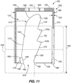
- the hole saw 1300 is operable to cut into two workpieces 1530 that defines a workpiece height 1535.
- the workpiece height 1535 is about 0.0762 meters (3 inches) (e.g., two standard 2 by 4 pieces of lumber). In other embodiments, the workpiece height 1535 can be less than 0.0762 meters (3 inches). In further embodiments, the workpiece height 1535 can be between about 0.0381 meters (1.5 inches) and about 0.0762 meters (3 inches). In yet further embodiments, the two workpieces 1530 can be formed as one workpiece with the workpiece height 1535. In operation, the cutting teeth 1475 cut into the two workpieces 1530, thereby forming workpiece chips that collect within the gullets 1375.
- the illustrated gullets 1375 include a particular volume to accommodate the workpiece chips as the hole saw 1300 cuts into the two workpieces 1530.
- a cylindrical workpiece plug will be removed from the cavity 1310 of the hole saw 1300.
- a user can grip the cylindrical workpiece plug (via their fingers) through the gullets 1375 to axially slide the cylindrical workpiece plug along the rotational axis 1350 and out of the cavity 1310.
- a tool can be inserted into one of the gullets 1375 to be supported on one of the support surfaces 1555a, 1555b for a user to leverage the cylindrical workpiece plug out of the hole saw 1300.
- FIG. 12 illustrates a planar view of a portion of a hole saw 1600 according to another embodiment.
- the hole saw 1600 is similar to the hole saw 100 of FIGS. 1-5 ; therefore, similar components are designated with similar references numbers plus 1500. At least some differences and/or at least some similarities between the hole saws 100, 1600 will be discussed in detail below.
- components or features described with respect to only one or some of the embodiments described herein are equally applicable to any other embodiments described herein within the scope of the claims and can include similar reference numbers.
- the hole saw 1600 can be sized to bore into the single workpiece 330 of FIG. 5 similar to the hole saw 100, or the hole saw 1600 can be sized to bore into the two workpieces 1530 of FIG. 11 similar to the hole saw 1300.
- the illustrated hole saw 1600 is moveable about a rotational axis 1650 in a cutting direction 1655 and includes a sidewall 1615 having a first end 1620 and a second end 1625.
- the sidewall 1615 also includes gullets 1675 (only one gullet 1675 is illustrated in FIG. 12 ) each defining a central longitudinal axis 1680.
- Each gullet 1675 includes a notch 1705, an open end 1685, a bottom surface 1690 defining a second radius 1745, a leading surface 1695, and a trailing surface 1700.
- Each trailing surface 1700 includes a trailing surface portion 1710 defining a first radius 1730, a first portion 1715, and a second portion 1720 with the trailing surface portion 1710 positioned between the first portion 1715 and the second portion 1720.
- the sidewall 1615 also includes three support apertures 1880 (only one is illustrated in FIG. 12 ) each positioned at a substantially same location that is circumferentially between adjacent gullets 1675.
- each support aperture 1880 is positioned above the bottom surfaces 1690 of the gullets 1675.
- each support aperture 1880 is positioned above the trailing surface portions 1710 of the gullets 1675.
- Each support aperture 1880 is also positioned between adjacent gullets 1675 as to not circumferentially overlap with any portion of the gullets 1675.
- Each support aperture 1880 is oblong-shaped and includes a longitudinal axis that is substantially perpendicular to the rotational axis 1650.
- the support apertures 1880 function similar to the support surfaces illustrated within FIGS. 7-11 for a tool to be inserted into one of the support apertures 1880 to leverage and remove a cylindrical workpiece plug from the hole saw 1600.
- the sidewall 1615 can include fewer than or more than three support apertures 1880 and/or the support apertures 1880 can be located at different positions circumferentially around the sidewall 1615.
- the hole saw 1600 also includes cutting teeth 1775 (only one cutting tooth 1775 is illustrated in FIG. 12 ) each having a cutting tip 1780 and seated within one notch 1705.
- Each cutting tooth 1775 includes a rake surface 1785 and a relief surface 1790.
- FIG. 13 illustrates a planar view of a portion of a hole saw 1900 according to an example which is not according to the invention.
- the hole saw 1900 is similar to the hole saw 100 of FIGS. 1-5 ; therefore, similar components are designated with similar references numbers plus 1800. At least some differences and/or at least some similarities between the hole saws 100, 1900 will be discussed in detail below.
- the hole saw 1900 can be sized to bore into the single workpiece 330 of FIG. 5 similar to the hole saw 100, or the hole saw 1900 can be sized to bore into the two workpieces 1530 of FIG. 11 similar to the hole saw 1300.
- the illustrated hole saw 1900 is moveable about a rotational axis 1950 in a cutting direction 1955 and includes a sidewall 1915 having a first end 1920 and a second end 1925.
- the sidewall 1915 also includes gullets 1975 (only one gullet 1975 is illustrated in FIG. 13 ) each defining a central longitudinal axis 1980.
- Each gullet 1975 includes a notch 2005, an open end 1985, a bottom surface 1990 defining a second radius 2045, a leading surface 1995, and a trailing surface 2000.
- the second radius 2045 of each bottom surface 1990 extends directly from the trailing surface 2000 to the leading surface 1995.
- the sidewall 1915 also includes three support apertures 2180 (only one is illustrated in FIG. 13 ) each positioned below the bottom surfaces 1900.
- Each support aperture 2180 is also positioned as to circumferentially overlap with one of the gullets 1975.
- the hole saw 1900 also includes cutting teeth 2075 (only one cutting tooth 2075 is illustrated in FIG. 13 ) each having a cutting tip 2080 and seated within one notch 2005.
- Each cutting tooth 2075 includes a rake surface 2085 and a relief surface 2090.
- FIG. 14 illustrates a planar view of a portion of a hole saw 2200 according to another embodiment.
- the hole saw 2200 is similar to the hole saw 100 of FIGS. 1-5 ; therefore, similar components are designated with similar references numbers plus 2100. At least some differences and/or at least some similarities between the hole saws 100, 2200 will be discussed in detail below.
- components or features described with respect to one or some of the embodiments described herein are equally applicable to any other embodiments described herein within the scope of the claims and can include similar reference numbers.
- the hole saw 2200 can be sized to bore into the single workpiece 330 of FIG. 5 similar to the hole saw 100, or the hole saw 2200 can be sized to bore into the two workpieces 1530 of FIG. 11 similar to the hole saw 1300.
- the illustrated hole saw 2200 is moveable about a rotational axis 2250 in a cutting direction 2255 and includes a sidewall 2215 having a first end 2220 and a second end 2225.
- the sidewall 2215 also includes gullets 2275 (only one gullet 2275 is illustrated in FIG. 14 ) each defining a central longitudinal axis 2280.
- Each gullet 2275 includes a notch 2305, an open end 2285, a bottom surface 2290 defining a second radius 2345, a leading surface 2295, and a trailing surface 2300.
- Each trailing surface 2300 includes a trailing surface portion 2310 defining a first radius 2330, a first portion 2315, and a second portion 2320 with the trailing surface portion 2310 positioned between the first portion 2315 and the second portion 2320.
- the first portion 2315 of each gullet 2275 defines a third angle 2440 that extends from the notch 2305 to the trailing surface portion 2310 in a direction away from the cutting direction 2255.
- the trailing surface portion 2310 is positioned behind the first portion 2315 relative to the cutting direction 2255.
- the third angle 2440 can be oriented in a direction toward the cutting direction 2255 with at least a portion of the trailing surface portion 2310 positioned behind a portion of the first portion 2315 in a direction relative to the cutting direction 2255.
- the sidewall 2215 also includes three support apertures 2480 (only one is illustrated in FIG. 14 ) each positioned below a trailing surface portion 2310.
- the hole saw 2200 also includes cutting teeth 2375 (only one cutting tooth 2375 is illustrated in FIG. 14 ) each having a cutting tip 2380 and seated within one notch 2305.
- Each cutting tooth 2375 includes a rake surface 2385 and a relief surface 2390.
- FIG. 15 illustrates a planar view of a portion of a hole saw 2500 according to an example which is not according to the invention.
- the hole saw 2500 is similar to the hole saw 100 of FIGS. 1-5 ; therefore, similar components are designated with similar references numbers plus 2400. At least some differences and/or at least some similarities between the hole saws 100, 2500 will be discussed in detail below.
- the hole saw 2500 can be sized to bore into the single workpiece 330 of FIG. 5 similar to the hole saw 100, or the hole saw 2500 can be sized to bore into the two workpieces 1530 of FIG. 11 similar to the hole saw 1300.
- the illustrated hole saw 2500 is moveable about a rotational axis 2550 in a cutting direction 2555 and includes a sidewall 2515 having a first end 2520 and a second end 2525.
- the sidewall 2515 also includes gullets 2575 (only one gullet 2575 is illustrated in FIG. 15 ) each defining a central longitudinal axis 2580.
- Each gullet 2575 includes a notch 2605, an open end 2585, a bottom surface 2590 defining a second radius 2645, a leading surface 2595, and a trailing surface 2600.
- Each leading surface 2595 includes a support surface 2755 positioned between a third portion 2745 and a fourth portion 2750.
- the hole saw 2500 also includes cutting teeth 2675 (only one cutting tooth 2675 is illustrated in FIG. 15 ) each having a cutting tip 2680 and seated within one notch 2605.
- Each cutting tooth 2675 includes a rake surface 2685 and a relief surface 2690.
- FIG. 16 illustrates a planar view of a portion of a hole saw 2800 according to another embodiment.
- the hole saw 2800 is similar to the hole saw 100 of FIGS. 1-5 ; therefore, similar components are designated with similar references numbers plus 2700. At least some differences and/or at least some similarities between the hole saws 100, 2800 will be discussed in detail below.
- components or features described with respect to one or some of the embodiments described herein are equally applicable to any other embodiments described herein within the scope of the claims and can include similar reference numbers.
- the hole saw 2800 can be sized to bore into the single workpiece 330 of FIG. 5 similar to the hole saw 100, or the hole saw 2800 can be sized to bore into the two workpieces 1530 of FIG. 11 similar to the hole saw 1300.
- the illustrated hole saw 2800 is moveable about a rotational axis 2850 in a cutting direction 2855 and includes a sidewall 2815 having a first end 2820 and a second end 2825.
- the sidewall 2815 also includes gullets 2875 (only one gullet 2875 is illustrated in FIG. 16 ) each defining a central longitudinal axis 2880.
- Each gullet 2875 includes a notch 2905, an open end 2885, a bottom surface 2890 defining a second radius 2945, a leading surface 2895, and a trailing surface 2900.
- Each trailing surface 2900 includes a trailing surface portion 2910 defining a first radius 2930, a first portion 2915, and a second portion 2920 with the trailing surface portion 2910 positioned between the first portion 2915 and the second portion 2920.
- the sidewall 2815 also includes three support apertures 3080 (only one is illustrated in FIG. 16 ).
- Each support aperture 3080 defines a greater area than an area of one of the gullets 2875.
- Each support aperture 3080 circumferentially overlaps with one of the gullets 2875 so that the leading surface 2895 of the gullet 2875 is positioned forward the support aperture 3080 but a portion of the support aperture 3080 is positioned behind the trailing surface 2900 of the gullet 2875 relative to the cutting direction 2855.
- the hole saw 2800 also includes cutting teeth 2975 (only one cutting tooth 2975 is illustrated in FIG. 16 ) each having a cutting tip 2980 and seated within one notch 2905.
- Each cutting tooth 2975 includes a rake surface 2985 and a relief surface 2990.
- FIG. 17 illustrates a planar view of a portion of a hole saw 3100 according to another embodiment.
- the hole saw 3100 is similar to the hole saw 100 of FIGS. 1-5 ; therefore, similar components are designated with similar references numbers plus 3000. At least some differences and/or at least some similarities between the hole saws 100, 3100 will be discussed in detail below.
- components or features described with respect to one or some of the embodiments described herein are equally applicable to any other embodiments described herein within the scope of the claims and can include similar reference numbers.
- the hole saw 3100 can be sized to bore into the single workpiece 330 of FIG. 5 similar to the hole saw 100 or the hole saw 3100 can be sized to bore into the two workpieces 1530 of FIG. 11 similar to the hole saw 1300.
- the illustrated hole saw 3100 is moveable about a rotational axis 3150 in a cutting direction 3155 and includes a sidewall 3115 having a first end 3120 and a second end 3125.
- the sidewall 3115 also includes gullets 3175 (only one gullet 3175 is illustrated in FIG. 17 ) each defining a central longitudinal axis 3180.
- Each gullet 3175 includes a notch 3205, an open end 3185, a bottom surface 3190 defining a second radius 3245, a leading surface 3195, and a trailing surface 3200.
- Each trailing surface 3200 includes a trailing surface portion 3210 defining a first radius 3230, a first portion 3215, and a second portion 3220 with the trailing surface portion 3210 positioned between the first portion 3215 and the second portion 3220.
- the sidewall 3115 also includes three support apertures 3380 (only one is illustrated in FIG. 17 ). Each support aperture 3380 circumferentially overlaps with one of the gullets 3175 so that a portion of the support aperture 3380 is positioned forward the leading surface 3195 but a portion of the first portion 3215 is positioned behind the support aperture 3380 relative to the cutting direction 3155.
- the hole saw 3100 also includes cutting teeth 3275 (only one cutting tooth 3275 is illustrated in FIG. 17 ) each having a cutting tip 3280 and seated within one notch 3205.
- Each cutting tooth 3275 includes a rake surface 3285 and a relief surface 3290.
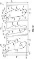
- FIG. 18 illustrates a planar view of a portion of a hole saw 3400 according to an example which is not according to the invention.
- the hole saw 3400 is similar to the hole saw 100 of FIGS. 1-5 ; therefore, similar components are designated with similar references numbers plus 3300. At least some differences and/or at least some similarities between the hole saws 100, 3400 will be discussed in detail below.
- the hole saw 3400 can be sized to bore into the single workpiece 330 of FIG. 5 similar to the hole saw 100, or the hole saw 3400 can be sized to bore into the two workpieces 1530 of FIG. 11 similar to the hole saw 1300.
- the illustrated hole saw 3400 is moveable about a rotational axis 3450 in a cutting direction 3455 and includes a sidewall 3415 having a first end 3420 and a second end 3425.
- the sidewall 3415 also includes three pairs of gullets 3475 (only one pair of gullets 3475 is illustrated in FIG. 18 ).
- Each pair 3475 includes a smaller gullet 3475a defining a central longitudinal axis 3480a and a larger gullet 3475b defining a central longitudinal axis 3480b.
- the central longitudinal axes 3480a, 3480b are substantially parallel; however, in other examples, the central longitudinal axes 3480a, 3480b can be obliquely angled.
- the smaller gullet 3475a includes a notch 3505a, an open end 3485a, a bottom surface 3490a defining a second radius 3545a, a leading surface 3495a, and a trailing surface 3500a.
- the larger gullet 3475b includes a notch 3505b, an open end 3485b, a bottom surface 3490b defining a second radius 3545b, a leading surface 3495b, and a trailing surface 3500b.
- the bottom surface 3490b of the larger gullet 3475b is positioned closer to the second end 3425 of the sidewall 3415 than the bottom surface 3490a of the smaller gullet 3475a.
- the sidewall 3415 can include fewer or more than three pairs of gullets 3475.
- the second radius 3545b of the larger gullet 3475b is greater than the second radius 3545a of the smaller gullet 3475a.
- the second radius 3545b of the larger gullet 3475b can be equal to or less than the second radius 3545a of the smaller gullet 3475a.
- the hole saw 3400 also includes cutting teeth 3575 (only one pair of cutting teeth 3575 are illustrated in FIG. 18 ) each having a cutting tip 3580 and seated within one notch 3505a, 3505b.
- Each cutting tooth 3575 includes a rake surface 3585 and a relief surface 3590.
- FIG. 19 illustrates a planar view of a portion of a hole saw 3700 according to another embodiment.
- the hole saw 3700 is similar to the hole saw 100 of FIGS. 1-5 ; therefore, similar components are designated with similar references numbers plus 3600. At least some differences and/or at least some similarities between the hole saws 100, 3700 will be discussed in detail below.
- components or features described with respect to one or some of the embodiments described herein are equally applicable to any other embodiments described herein within the scope of the claims and can include similar reference numbers.
- the hole saw 3700 can be sized to bore into the single workpiece 330 of FIG. 5 similar to the hole saw 100, or the hole saw 3700 can be sized to bore into the two workpieces 1530 of FIG. 11 similar to the hole saw 1300.
- the illustrated hole saw 3700 is moveable about a rotational axis 3750 in a cutting direction 3755 and includes a sidewall 3715 having a first end 3720 and a second end 3725.
- the sidewall 3715 also includes gullets 3775 (only one gullet 3775 is illustrated in FIG. 19 ) each defining a central longitudinal axis 3780 parallel to the rotational axis 3750.
- Each gullet 3775 includes a notch 3805, an open end 3785, a bottom surface 3790 defining a second radius 3845, a leading surface 3795, and a trailing surface 3800.
- Each trailing surface 3800 includes a trailing surface portion 3810 defining a first radius 3830, a first portion 3815, and a second portion 3820 with the trailing surface portion 3810 positioned between the first portion 3815 and the second portion 3820.
- the sidewall 3715 also includes three support apertures 3980 (only one is illustrated in FIG. 19 ).
- Each support aperture 3980 defines a longitudinal axis that substantially aligns with one central longitudinal axis 3780 of one gullet 3775. In particular, each support aperture 3980 is directly below one gullet 3775.
- the hole saw 3700 also includes cutting teeth 3875 (only one cutting tooth 3875 is illustrated in FIG. 19 ) each having a cutting tip 3880 and seated within one notch 3805.
- Each cutting tooth 3875 includes a rake surface 3885 and a relief surface 3890.
Description
- The present invention relates to hole saws according to the preamble of claim 1, and more particularly to gullets formed in the hole saws. Such hole saws are known from
US-A-2014/023447 . According to its abstract,US-A-2014/023447 describes a cutting tool including a generally cylindrical body, a plurality of cutting teeth formed on the generally cylindrical body, a plurality of non-cutting protrusions formed on the generally cylindrical body, and a plurality of gullets formed on the generally cylindrical body. Each gullet is formed between one of the plurality of cutting teeth and one of the plurality of non-cutting protrusions. Each gullet has a base and a gullet depth measured from the base to a tip of a corresponding cutting tooth. Each non-cutting protrusion is located approximately halfway between the tips of two adjacent cutting teeth and has a height that is at most about 75% of the gullet depth.DE-U-202004003900 describes a centering drilling unit. According to its abstract,FR-A-2302808 - According to the invention, a hole saw is movable about a rotational axis in a cutting direction to cut into a workpiece. The hole saw includes a cylindrical body having a sidewall with a first end and a second end opposite the first end. The cylindrical body also includes a gullet formed in the sidewall between a leading surface, a trailing surface, and a bottom surface of the sidewall. The trailing surface defines a portion having a first radius. The bottom surface has a second radius. The first radius is larger than the second radius. The hole saw also includes a cutting tooth coupled to the first end of the sidewall adj acent the gullet. A first portion of the trailing surface extending between the cutting tooth and the curved portion is a substantially linear surface. In a preferred embodiment the gullet may define a central longitudinal axis extending between the first and second ends of the sidewall. The central longitudinal axis may be obliquely oriented relative to the rotational axis such that the gullet is angled from the first end to the bottom surface in a direction toward the cutting direction. The central longitudinal axis may be oriented at an angle between about 5 degress and about 15 degrees relative to the rotational axis. In a further preferred embodiment a ratio of the first radius to the second radius may be between about 2.5 and about 5. In a further preferred embodiment the first radius may be between about 0.0254 meters (1 inch) and about 0.03175meters (1.25 inches). The second radius may be between about 0.00635meters (0.25 inches) and about 0.1016meters (0.4 inches). In a further preferred embodiment the sidewall may include a support surface in the leading surface that faces the first end. The support surface may be configured to support a tool to leverage material out of the cylindrical body. The support surface may be a first support surface. The sidewall may include a second support surface in the leading surface that faces the first end. The second support surface may be configured to support the tool to leverage material of the cylindrical body. In a further preferred embodiment the cylindrical body may include two gullets. The sidewall may define an aperture positioned between the two gullets. The aperture may be configured to receive a tool to leverage material out of the cylindrical body. In a further preferred embodiment the cylindrical body may include less than three gullets. The cylindrical body may define a maximum diameter equal to or less than about 0.05715meters (2.25 inches). In a further preferred embodiment the gullet may extend through the first end of the sidewall. A distance between the leading surface and a tip of the cutting tooth in a direction perpendicular to the rotational axis may be between about 0.0127meters (0.5 inches) and about 0.01778meters (0.7 inches). In a further preferred embodiment a dimension parallel to the rational axis may be defined between the first end of the sidewall and the bottom surface of the gullet. The dimension may be greater than 0.0381meters (1.5 inches). In a further preferred embodiment the cylindrical body may be made of a first material. The cutting tool may be made of a second material different than the first material. The cutting tooth may be fixedly attached to the sidewall adjacent the trailing surface. The cutting tooth may be a carbide cutting tooth. In a further preferred embodiment the cutting tooth may include a rake surface. The rake surface may be oriented at a positive rake angle. In a further preferred embodiment the cylindrical body may include an end cap coupled to the second end of the sidewall. The end cap may be configured to allow for a power tool to be coupled to the hole saw.
- In a further preferred embodiment, the gullet defines a central longitudinal axis extending between the first and second ends of the sidewall that is obliquely oriented relative to the rotational axis such that the gullet is angled from the first end to the bottom surface in a direction toward the cutting direction. The gullet has a dimension measured parallel to the rotational axis between the first end of the sidewall and the bottom surface of the gullet that is greater than 0.0381meters (1.5 inches). In a preferred embodiment the central longitudinal axis may be oriented at an angle between about 1 degree and about 40 degrees relative to the rotational axis. The central longitudinal axis may be oriented at an angle between about 5 degrees and about 15 degrees relative to the rotational axis. In a further preferred embodiment the dimension may be greater than 0.0762meters (3 inches). In a further preferred embodiment the dimension may be between 0.0381meters (1.5 inches) and about 0.0508meters (2.0 inches).
- In a further preferred embodiment, the gullet extends through the first end of the sidewall and defines a central longitudinal axis extending between the first and second ends of the sidewall. The central longitudinal axis is obliquely oriented relative to the rotational axis such that the gullet is angled from the first end to the bottom surface in a direction toward the cutting direction. A dimension measured between the leading surface and a tip of the cutting tooth in a direction perpendicular to the rotational axis is between about 0.0127meters (0.5 inches) and about 0.1778meters (0.7 inches). In a preferred embodiment the central longitudinal axis may be oriented at an angle between about 1 degree and about 40 degrees relative to the rotational axis. The central longitudinal axis may be oriented at an angle between about 5 degrees and about 15 degrees relative to the rotational axis.
- In another preferred embodiment, the gullet extends through the first end of the sidewall and defines a central longitudinal axis extending between the first and second ends of the sidewall. The central longitudinal axis is obliquely oriented relative to the rotational axis such that the gullet is angled from the first end to the bottom surface in a direction toward the cutting direction. The gullet has a first dimension measured parallel to the rotational axis between the first end of the sidewall and the bottom surface of the gullet that is greater than 0.0381 meters (1.5 inches). A second dimension measured perpendicular to the rotational axis between the leading surface and a tip of the cutting tooth is between about 0.0127 meters (0.5 inches) and about 0.01778 meters (0.7 inches). In a preferred embodiment the cutting tooth may be a carbide cutting tooth secured to the first end of the sidewall. In a further preferred embodiment the cylindrical body may include an end cap coupled to the second end of the sidewall. The end cap may be configured to allow for a power tool to be coupled to the hole saw.
- Other aspects of the invention will become apparent by consideration of the detailed description and accompanying drawings.
-
-
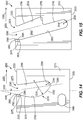
FIG. 1 is a perspective view of a hole saw according to one embodiment of the invention coupled to a power tool. -
FIG. 2 is an end view of the hole saw ofFIG. 1 . -
FIG. 3 is a side view of the hole saw ofFIG. 1 in a flattened state and illustrating three gullets. -
FIG. 4 is a detailed view of a portion of the hole saw ofFIG. 3 . -
FIG. 5 is a cross sectional view of the hole saw taken along line 5-5 ofFIG. 2 illustrating the hole saw cutting through a workpiece. -
FIG. 6 is a planar side view of a hole saw according to another embodiment of the invention. -
FIG. 7 is a planar side view of a hole saw according to another embodiment of the invention. -
FIG. 8 is a planar side view of a hole saw according to another embodiment of the invention. -
FIG. 9 is a perspective view of a hole saw according to another embodiment of the invention. -
FIG. 10 is a side view of the hole saw ofFIG. 9 in a flattened state and illustrating three gullets. -
FIG. 11 is a cross sectional view of the hole saw taken along line 11-11 ofFIG. 9 with the hole saw cutting through two workpieces. -
FIG. 12 is a planar side view of a hole saw according to another embodiment of the invention. -
FIG. 13 is a planar side view of a hole saw according to an example which is not according to the invention. -
FIG. 14 is a planar side view of a hole saw according to another embodiment of the invention. -
FIG. 15 is a planar side view of a hole saw according to an example which is not according to the invention. -
FIG. 16 is a planar side view of a hole saw according to another embodiment of the invention. -
FIG. 17 is a planar side view of a hole saw according to another embodiment of the invention. -
FIG. 18 is a planar side view of a hole saw according to an example which is not according to the invention. -
FIG. 19 is a planar side view of a hole saw according to another embodiment of the invention. - Before any embodiments of the invention are explained in detail, it is to be understood that the invention is not limited in its application to the details of construction and the arrangement of components set forth in the following description or illustrated in the following drawings. The invention is capable of other embodiments and of being practiced or of being carried out in various ways, within the scope of the claims. Also, it is to be understood that the phraseology and terminology used herein is for the purpose of description and should not be regarded as limiting. The use of "including," "comprising," or "having" and variations thereof herein is meant to encompass the items listed thereafter as well as additional items. Unless specified or limited otherwise, the terms "mounted," "connected," "supported," and "coupled" and variations thereof are used broadly and encompass both direct and indirect mountings, connections, supports, and couplings. Further, "connected" and "coupled" are not restricted to physical or mechanical connections or couplings. Terms of degree, such as "about," "substantially," or "approximately" are understood by those of ordinary skill to refer to reasonable ranges outside of the given value, for example, general tolerances associated with manufacturing, assembly, and use of the described embodiments.
-
FIGS. 1-5 illustrate ahole saw 100 including acylindrical body 105 defining acavity 110. Thecylindrical body 105 includes asidewall 115 having afirst end 120 and asecond end 125 with thesecond end 125 positioned opposite thefirst end 120. Thehole saw 100 also includes anend cap 130 coupled to thesecond end 125 and has anaperture 135 sized to receive anarbor 140 such that thehole saw 100 can be coupled to and driven by a tool 145 (e.g., a power drill or the like) via thearbor 140. Thetool 145 drives thehole saw 100 about arotational axis 150 in a cutting direction 155 (FIG. 2 ). In the illustrated embodiment, thearbor 140 is selectively coupled to theend cap 130, but in other embodiments, thearbor 140 can be fixedly coupled to theend cap 130. In some embodiments, a pilot drill bit 156 (e.g., a twist drill bit, a spade drill bit, etc.) can be selectively or fixedly coupled to thearbor 140 to extend through thecavity 110 and beyond thefirst end 120 of thesidewall 115. The illustratedcylindrical body 105 is made of a metallic material (e.g., low carbon steel, etc.). In other embodiments, thecylindrical body 105 can be made of a different metallic material (e.g., high carbon steel, etc.). - As best shown in
FIG. 2 , thesidewall 115 defines a maximumouter diameter 160. Theouter diameter 160 can be between about 0.0254 meters (1 inch) and about 0.1778 meters (7 inches). In some embodiments, theouter diameter 160 can be about 0.034798 meters (1.37 inches), about 0.065024 meters (2.56 inches), about 0.1016 meters (4 inches), or about 0.15875 meters (6.25 inches). In further embodiments, theouter diameter 160 can be greater than 0.1778 meters (7 inches). Thesidewall 115 also defines amaximum thickness 165. Thethickness 165 can be between about 0.001778 meters (0.07 inches) and about 0.002794 meters (0.11 inches). In some embodiments, thethickness 165 can be about 0.002032 meters (0.08 inches), about 0.002286 meters (0.09 inches), about 0.00254 meters (0.1 inches), or about 0.0026416 meters (0.104 inches). As best shown inFIG. 3 , thesidewall 115 further defines a sidewall height ordimension 170 extending between thefirst end 120 and thesecond end 125 in a direction parallel to therotational axis 150. The illustratedsidewall height 170 is between about 0.0635 meters (2.5 inches) and about 0.0762 meters (3 inches). In other embodiments, thesidewall height 170 can be between about 0.0381 meters (1.5 inches) and about 0.127 meters (5 inches). - In the illustrated embodiment, the
sidewall 115 includes threegullets 175 equally spaced about the rotational axis 150 (e.g., eachgullet 175 is spaced about 120 degrees relative to an adjacent gullet 175). In other embodiments, thehole saw 100 can include more than three gullets 175 (e.g., four, five, six, etc.) or can include less than three gullets (e.g., two or one) with thegullets 175 equally or non-equally spaced about therotational axis 150. For example, thehole saw 100 can include two gullets 175 (spaced 180 degrees apart) when theouter diameter 160 is less than about 0.05715 meters (2.25 inches). - With reference to
FIG. 3 , eachgullet 175 defines a centrallongitudinal axis 180 extending between thefirst end 120 and thesecond end 125. Eachgullet 175 includes anopen end 185 adjacent thefirst end 120 and is defined by abottom surface 190 of thesidewall 115 opposite theopen end 185, a leadingsurface 195 of thesidewall 115 extending between theopen end 185 and thebottom surface 190, and a trailingsurface 200 of thesidewall 115 extending between theopen end 185 and thebottom surface 190. The leadingsurface 195 and the trailingsurface 200 of eachgullet 175 are in relation to the cuttingdirection 155 of the hole saw 100 (i.e., the leadingsurface 195 is forward the trailingsurface 200 as thehole saw 100 moves in the cutting direction 155). Each trailingsurface 200 includes a seat or notch 205 formed adjacent theopen end 185 and a trailingsurface portion 210 positioned between thenotch 205 and thebottom surface 190 in a direction parallel to therotational axis 150. In particular, afirst portion 215 of each trailingsurface 200 extends between thenotch 205 and the trailingsurface portion 210 and asecond portion 220 of each trailingsurface 200 extends between the trailingsurface portion 210 and thebottom surface 190. In addition, anedge 225 is positioned between the leadingsurface 195 and thefirst end 120 that defines a substantially 90 degree edge. In other embodiments, theedge 225 can be a curved edge. - In the illustrated embodiment, all three
gullets 175 include the substantially same geometry, but in other embodiments, two ormore gullets 175 can include different geometries. One of thegullets 175 will be described in detail below but can be applicable to one or more of the remaininggullets 175. The illustratedfirst portion 215 of the trailingsurface 200 is a substantially linear surface oriented substantially parallel to therotational axis 150. In addition, the centrallongitudinal axis 180 of thegullet 175 is parallel to therotational axis 150 so that thefirst portion 215 is also parallel to the centrallongitudinal axis 180. The illustrated trailingsurface portion 210 defines afirst radius 230 between about 0.0254 meters (1 inch) and about 0.03175 meters (1.25 inches). In other embodiments, thefirst radius 230 can be between about 0.03175 meters (1.25 inches) and about 2 inches or thefirst radius 230 can be between about 0.01016 meters (0.4 inches) and about 0.0254 meters (1 inch). In addition, the trailingsurface portion 210 is formed in a lower half of thegullet 175 in a direction parallel to therotational axis 150. The illustratedsecond portion 220 of the trailingsurface 200 is a substantially linear surface, but in other embodiments, thesecond portion 220 can be a curved surface. Thesecond portion 220 is also oriented at anoblique angle 235 relative to therotational axis 150. The illustratedoblique angle 235 is between about 40 degrees and about 50 degrees. In other embodiments, theoblique angle 235 can be between about 50 degrees and about 70 degrees or theoblique angle 235 can be between about 20 degrees and about 40 degrees. Afirst angle 240 is defined between thefirst portion 215 and thesecond portion 220. The illustratedfirst angle 240 is between about 130 degrees and about 140 degrees. In other embodiments, thefirst angle 240 can be between 140 degrees and about 170 degrees, or thefirst angle 240 can be between about 80 degrees and about 130 degrees. The illustratedbottom surface 190 defines asecond radius 245 between about 0.00635 meters (0.25 inches) and about 0.01016 (0.4 inches). In other embodiments, thesecond radius 245 can be between about 0.01016 meters (0.4 inches) and about 0.0254 meters (1 inch), or thesecond radius 245 can be between about 0.00254 meters (0.1 inches) and about 0.00635 meters (0.25 inches). In some embodiments, thesecond radius 245 can be equal to or less than thefirst radius 230. A ratio of thefirst radius 230 to thesecond radius 245 is between about 2.5 to about 5. In other embodiments, the ratio of thefirst radius 230 to thesecond radius 245 is between about 1 and about 6. In further embodiments, the ratio of thefirst radius 230 to thesecond radius 245 is between about 3 and about 4. - The illustrated leading
surface 195 is a substantially linear surface oriented substantially parallel to therotational axis 150. Asecond angle 250 is defined between thesecond portion 220 and the leadingsurface 195. The illustratedsecond angle 250 is between about 40 degrees and about 50 degrees. In other embodiments, thesecond angle 250 can be between 50 degrees and about 80 degrees or thesecond angle 250 can be between about 10 degrees and about 40 degrees. - With continued reference to
FIG. 3 , thegullet 175 defines a gullet height ordimension 255 extending between thefirst end 120 and thebottom surface 190 in a direction parallel to therotational axis 150. The illustratedgullet height 255 is greater than about 0.0381 meters (1.5 inches). In other embodiments, thegullet height 255 can be between about 0.04318 meters (1.7 inches) and about 0.04826 meters (1.9 inches), or thegullet height 255 can be between about 0.04826 meters (1.9 inches) and about 0.0762 meters (3 inches). As such, a ratio of thesidewall height 170 over thegullet height 255 is about 1.4. In other embodiments, the ratio of thesidewall height 170 over thegullet height 255 can be between about 1.1 and about 2. In further embodiments, the ratio of thesidewall height 170 over thegullet height 255 can be between about 2 and about 4. The illustratedsidewall 115 also defines aheight 260 extending between thebottom surface 190 of eachgullet 175 and thesecond end 125 of thesidewall 115. Theheight 260 is between about 0.01778 meters (0.7 inches) and about 0.02286 meters (0.9 inches). In other embodiments, theheight 260 can be between about 0.02286 meters (0.9 inches) and about 0.0381 meters (1.5 inches) or theheight 260 can be between about 0.00254 meters (0.1 inches) and about 0.01778 meters (0.7 inches). Thegullet 175 also defines amaximum gullet width 265 extending between the leadingsurface 195 and the trailingsurface 200 in a direction perpendicular to therotational axis 150. In particular, themaximum gullet width 265 extends between the leadingsurface 195 and apoint 270 located on thefirst portion 215 directly below thenotch 205. The illustratedmaximum gullet width 265 is between about 0.01905 meters (0.75 inches) and about 0.03048 meters (1.2 inches). In other embodiments, themaximum gullet width 265 can be between about 0.03048 meters (1.2 inches) and about 0.0381 meters (1.5 inches), or themaximum gullet width 265 can be between about 0.01016 meters (0.4 inches) and about 0.01905 meters (0.75 inches). - The
hole saw 100 also includes cuttingteeth 275 positioned adjacent thefirst end 120 of thesidewall 115. Each cuttingtooth 275 has acutting tip 280 positioned beyond the first end 120 (i.e., above thefirst end 120 as illustrated inFIG. 4 ). In particular, the cuttingteeth 275 are carbide cutting teeth that are seated within thenotches 205 of thesidewall 115 and secured to the sidewall 115 (e.g., by a brazing operation or the like). Thecarbide cutting teeth 275 include a material hardness that is greater than a material hardness of thesidewall 115. In other embodiments, the cuttingteeth 275 can be made of a different material (e.g., hardened steel, etc.). In further embodiments, thesidewall 115 can form the cuttingteeth 275 so that the cuttingteeth 275 are not separately secured to thesidewall 115. Each cuttingtooth 275 includes arake surface 285 and arelief surface 290 with eachrake surface 285 facing into one of thegullets 175. Eachrake surface 285 defines a positive rake angle 295 (e.g., angled toward the cutting direction 155) relative to therotational axis 150 between about 5 degrees and about 15 degrees. As such, aminimum gullet width 296 between each cuttingtip 280 and the corresponding leadingsurface 195 perpendicular to therotational axis 150 is between about 0.0127 meters (0.5 inches) and about 0.01778 meters (0.7 inches). In other embodiments, theminimum gullet width 296 can be between about 0.01778 meters (0.7 inches) and about 0.03048 meters (1.2 inches). In further embodiments, theminimum gullet width 296 can be greater than themaximum gullet width 265. In yet further embodiments, therake angle 295 can be a negative rake angle (e.g., angled away from the cutting direction 155). Atooth angle 300 is defined between therake surface 285 and therelief surface 290 between about 60 degrees and about 70 degrees (FIG. 4 ). As best shown inFIG. 2 , each cuttingtip 280 defines atip width 305 between about 0.00254 meters (0.1 inches) and about 0.00508 meters (0.2 inches). Thetip width 305 of each cuttingtooth 275 is greater than thethickness 165 of thesidewall 115. As such, a total cutting diameter of thehole saw 100 is greater than the maximumouter diameter 160 of thesidewall 115. In other embodiments, thetip width 305 can be substantially the same as thethickness 165 of thesidewall 115 with the cuttingteeth 275 bent radially inward or outward relative to therotational axis 150. - With continued reference to
FIG. 4 , a recess orrelief 310 is formed within thefirst end 120 of thesidewall 115 directly behind each cuttingtooth 275 with a trailingportion 315 of eachrecess 310 angled in a direction away from the cuttingdirection 155. Eachrecess 310 defines arecess angle 320 relative to therake surface 285 that is less than thetooth angle 300. As such, during a grinding process to shape the cutting teeth 275 (e.g., to shape the tooth angle 300), therecesses 310 provide enough clearance for a grinding wheel or the like to shape the cuttingteeth 275 without contacting thesidewall 115. - Once the cutting
teeth 275 are coupled to thesidewall 115, eachgullet 175 defines anarea 325 between therake surface 285, the trailingsurface 200, thebottom surface 190, and the leadingsurface 195. In the illustrated embodiment, thearea 325 of eachgullet 175 is equal to or greater than 0.0007742 meters squared (1.2 inches squared). In other embodiments, thearea 325 of eachgullet 175 is between about 0.0007742 meters squared (1.2 inches squared) and about 0.00225806 meters squared (3.5 inches squared). In further embodiments, thearea 325 of eachgullet 175 is between about 0.0007742 meters squared (1.2 inches squared) and about 0.00129032 meters squared (2 inches squared). As thehole saw 100 includes threegullets 175, the total area of the illustratedgullets 175 is equal to or greater than 0.00232258 meters squared (3.6 inches squared). Eachgullet 175 also defines a volume, which is determined by multiplying thearea 325 of eachgullet 175 by themaximum thickness 165 of thesidewall 115. As such, the volume of eachgullet 175 is equal to or greater than 1.3765 x 10⁻⁶ meters cubed (0.084 inches cubed). In some embodiments, a ratio of thetip width 305 over the volume of one of thegullets 175 is about 0.2. In other embodiments, the ratio of thetip width 305 over the volume of one of thegullets 175 can be between about 0.1 and about 1.1. - With reference to
FIG. 5 , thehole saw 100 is operable to cut into aworkpiece 330 that defines aworkpiece height 335. In the illustrated embodiment, theworkpiece height 335 is about - 0.0381 meters (1.5 inches) (e.g., height of a standard 2 by 4 piece of lumber). In other embodiments, theworkpiece height 335 can be less than 0.0381 meters (1.5 inches). In operation, the cuttingteeth 275 cut into theworkpiece 330, thereby forming workpiece chips that collect within thegullets 175. As thehole saw 100 bores deeper into theworkpiece 330, more workpiece chips are collected within thegullets 175. Accordingly, the illustratedgullets 175 include a particular volume to accommodate the workpiece chips as thehole saw 100 cuts into theworkpiece 330. If the volume of thegullets 175 is not sufficient to accommodate the workpiece chips, the workpiece chips will build up within thegullets 175 and decrease the efficiency of thehole saw 100 cutting into theworkpiece 330. Once thehole saw 100 bores through theworkpiece 330, a cylindrical workpiece plug will be removed from thecavity 110 of thehole saw 100. In particular, a user can grip the cylindrical workpiece plug (via their fingers) through thegullets 175 to axially slide the cylindrical workpiece plug along the rotational axis and out of thecavity 110. Theminimum gullet width 296 of eachgullet 175 is sized to provide enough clearance between each cuttingtip 280 and the corresponding leadingsurface 195 so that a user's finger avoids contact with the cuttingtip 280 as the cylindrical workpiece plug is removed from thehole saw 100. -
FIG. 6 illustrates a planar view of a portion of ahole saw 400 according to another embodiment. Thehole saw 400 is similar to thehole saw 100 ofFIGS. 1-5 ; therefore, similar components are designated with similar references numbers plus 300. At least some differences and/or at least some similarities between the hole saws 100, 400 will be discussed in detail below. In addition, components or features described with respect to one or some of the embodiments described herein are equally applicable to any other embodiments described herein within the scope of the claims and can include similar reference numbers. - The illustrated
hole saw 400 is moveable about arotational axis 450 in acutting direction 455 and includes asidewall 415 having afirst end 420 and asecond end 425. Thesidewall 415 also includes gullets 475 (only onegullet 475 is illustrated inFIG. 6 ) each defining a centrallongitudinal axis 480. Eachgullet 475 includes anotch 505, anopen end 485, abottom surface 490 defining asecond radius 545, a leadingsurface 495, and a trailingsurface 500. Each trailingsurface 500 includes a trailingsurface portion 510 defining afirst radius 530, afirst portion 515, and asecond portion 520 with the trailingsurface portion 510 positioned between thefirst portion 515 and thesecond portion 520. In the illustrated embodiment, eachfirst portion 515 is parallel to the leadingsurface 495; however, in other embodiments, thefirst portion 515 can be obliquely angled relative to the leadingsurface 495. In the illustrated embodiment, thefirst portion 515 of each trailingsurface 500 is oriented at athird angle 640 between about 5 degrees and about 15 degrees relative to therotational axis 450 so that thefirst portion 515 is angled from thefirst end 420 to thesecond end 425 in a direction toward the cuttingdirection 455. As a result, each centrallongitudinal axis 480 is also oriented between about 5 degrees and about 15 degrees relative to therotational axis 450 so that the centrallongitudinal axis 480 is angled from thefirst end 420 to thesecond end 425 in a direction toward the cuttingdirection 455. In other embodiments, thethird angle 640 is greater than about 5 degrees. In further embodiments, thethird angle 640 is less than about 15 degrees. In yet further embodiments, thethird angle 640 is between about 1 degree and about 40 degrees. - The
hole saw 400 also includes cutting teeth 575 (only onecutting tooth 575 is illustrated inFIG. 6 ) each having a cuttingtip 580 and seated within onenotch 505. Each cuttingtooth 575 includes arake surface 585 and arelief surface 590. -
FIG. 7 illustrates a planar view of a portion of ahole saw 700 according to another embodiment. Thehole saw 700 is similar to thehole saw 100 ofFIGS. 1-5 ; therefore, similar components are designated with similar references numbers plus 600. At least some differences and/or at least some similarities between the hole saws 100, 700 will be discussed in detail below. In addition, components or features described with respect to one or some of the embodiments described herein are equally applicable to any other embodiments described herein within the scope of the claims and can include similar reference numbers. - The illustrated
hole saw 700 is moveable about arotational axis 750 in acutting direction 755 and includes asidewall 715 having afirst end 720 and asecond end 725. Thesidewall 715 also includes gullets 775 (only onegullet 775 is illustrated inFIG. 7 ) each defining a centrallongitudinal axis 780. Eachgullet 775 includes anotch 805, anopen end 785, abottom surface 790 defining asecond radius 845, a leadingsurface 795, and a trailingsurface 800. Each trailingsurface 800 includes a trailingsurface portion 810 defining afirst radius 830, afirst portion 815, and asecond portion 820 with the trailingsurface portion 810 positioned between thefirst portion 815 and thesecond portion 820. Each leadingsurface 795 includes athird portion 945, afourth portion 950, and asupport surface 955 positioned between thethird portion 945 and thefourth portion 950 in a direction parallel to therotational axis 750. Thesupport surface 955 is also positioned at asupport surface distance 960 between about 0.01778 meters (0.7 inches) and about 0.0254 meters (1 inch) from thefirst end 720 of thesidewall 715. In other embodiments, thesupport surface 955 can be formed within at least one of thegullets 775. In the illustrated embodiment, thethird portion 945 is oriented parallel to thefourth portion 950 of eachleading surface 795 and thefirst portion 815 of each trailingsurface 800. Eachthird portion 945 andfourth portion 950 are also offset (e.g., nonlinear) relative to each other. In other embodiments, thethird portion 945 can be obliquely angled relative to thefirst portion 815 and/or thefourth portion 950. Eachsupport surface 955 is oriented at asupport angle 965 relative to therotational axis 750. Thesupport angle 965 is less than 90 degrees relative to therotational axis 750 so that thesupport surface 955 is angled downwardly and toward the cutting direction 755 (e.g., thesupport surface 955 generally faces upwardly toward the first end 720). In other embodiments, thesupport angle 965 can be less than 90 degrees and greater than 75 degrees relative to therotational axis 750. Also, eachsupport surface 955 is positioned above the trailingsurface portion 810 in a direction parallel to therotational axis 750. In other embodiments, eachsupport surface 955 can be positioned at the same height of the trailingsurface portion 810 or positioned below the trailingsurface portion 810. - The
hole saw 700 also includes cutting teeth 875 (only onecutting tooth 875 is illustrated inFIG. 7 ) each having a cuttingtip 880 and seated within onenotch 805. Each cuttingtooth 875 includes arake surface 885 and arelief surface 890. - In operation, a cylindrical workpiece plug can be removed from the
hole saw 700 by using a tool (e.g., a screwdriver or the like). In particular, the tool is inserted within one of thegullets 775 below the cylindrical workpiece plug. In some embodiments, the tool engages thebottom surface 790 of thegullet 775 to leverage and push the cylindrical workpiece plug out of thefirst end 720. The tool can also engage thesupport surface 955 to leverage and push the cylindrical workpiece plug out of thefirst end 720. As thesupport surface 955 is angled downwardly and toward the cuttingdirection 755, the tool can be captured on thesupport surface 955 without sliding into thegullet 775 as the tool is used to leverage the cylindrical workpiece plug out of thehole saw 700. -
FIG. 8 illustrates a planar view of a portion of ahole saw 1000 according to another embodiment. Thehole saw 1000 is similar to thehole saw 100 ofFIGS. 1-5 ; therefore, similar components are designated with similar references numbers plus 900. At least some differences and/or at least some similarities between the hole saws 100, 1000 will be discussed in detail below. In addition, components or features described with respect to only one or some of the embodiments described herein are equally applicable to any other embodiments described herein within the scope of the claims and can include similar reference numbers. - The illustrated
hole saw 1000 is moveable about arotational axis 1050 in acutting direction 1055 and includes asidewall 1015 having afirst end 1020 and asecond end 1025. Thesidewall 1015 also includes gullets 1075 (only onegullet 1075 is illustrated inFIG. 8 ) each defining a centrallongitudinal axis 1080. Eachgullet 1075 includes anotch 1105, anopen end 1085, abottom surface 1090 defining asecond radius 1145, a leadingsurface 1095, and a trailingsurface 1100. Each trailingsurface 1100 includes a trailingsurface portion 1110 defining afirst radius 1130, afirst portion 1115, and asecond portion 1120 with the trailingsurface portion 1110 positioned between thefirst portion 1115 and thesecond portion 1120. Each leadingsurface 1095 includes athird portion 1245, afourth portion 1250, and a support surface 1255 (similar to thesupport surface 955 ofFIG. 7 ) formed on aprotrusion 1270 of thesidewall 1015, which extends into eachgullet 1075. The illustratedthird portion 1245 andfourth portion 1250 are substantially collinear surfaces with thesupport surface 1255 oriented at a substantially 90 degree angle relative to therotational axis 1050. - The
hole saw 1000 also includes cutting teeth 1175 (only onecutting tooth 1175 is illustrated inFIG. 8 ) each having acutting tip 1180 and seated within onenotch 1105. Each cuttingtooth 1175 includes arake surface 1185 and arelief surface 1190. -
FIGS. 9-11 illustrate ahole saw 1300 according to another embodiment. Thehole saw 1300 is similar to thehole saw 100 ofFIGS. 1-5 ; therefore, similar components are designated with similar references numbers plus 1200. At least some differences and/or at least some similarities between the hole saws 100, 1300 will be discussed in detail below. In addition, components or features described with respect to one or some of the embodiments described herein are equally applicable to any other embodiments described herein within the scope of the claims and can include similar reference numbers. - The illustrated
hole saw 1300 is moveable about arotational axis 1350 in acutting direction 1355 and includes acylindrical body 1305 having asidewall 1315 that defines acavity 1310 and anend cap 1330 having anaperture 1335. Thesidewall 1315 includes afirst end 1320 and asecond end 1325. Thesidewall 1315 defines a maximum outer diameter 1360 (FIG. 11 ), a maximum thickness 1365 (FIG. 11 ), and a sidewall height or dimension 1370 (FIG. 10 ) extending between thefirst end 1320 and thesecond end 1325 in a direction parallel to therotational axis 1350. Thesidewall height 1370 can be between about 0.08382 meters (3.3 inches) and about 0.09398 meters (3.7 inches). In other embodiments, thesidewall height 1370 can be between about 0.09398 meters (3.7 inches) and about 0.1143 meters (4.5 inches). Thesidewall 1315 also includesgullets 1375 each defining a centrallongitudinal axis 1380 oriented at an oblique angle (e.g., between about 5 degrees and about 15 degrees) relative to therotational axis 1350. Eachgullet 1375 includes anotch 1405, an open end 1385, abottom surface 1390 defining asecond radius 1445, a leadingsurface 1395, and a trailingsurface 1400. Each trailingsurface 1400 includes a trailingsurface portion 1410 defining afirst radius 1430, afirst portion 1415, and asecond portion 1420 with the trailingsurface portion 1410 positioned between thefirst portion 1415 and thesecond portion 1420. Each leadingsurface 1395 includes anedge 1425 and twosupport surfaces FIGS. 7 and8 ) so that each leadingsurface 1395 includes athird portion 1545, afourth portion 1550, and afifth portion 1575. With the twosupport surfaces surface 1395, the leadingsurface 1395 defines a zig-zag shaped surface. The illustratedthird portion 1545,fourth portion 1550, andfifth portion 1575 are all linear surfaces with thethird portion 1545 obliquely oriented relative to thefourth portion 1550 and thefourth portion 1550 oriented substantially parallel to thefifth portion 1575. In other embodiments, two or more of thethird portion 1545, thefourth portion 1550, and thefifth portion 1575 can be substantially parallel relative to each other or obliquely oriented relative to each other. In further embodiments, at least one of thethird portion 1545, thefourth portion 1550, and thefifth portion 1575 can be a curved surface. In yet further embodiments, thethird portion 1545, thefourth portion 1550, thefifth portion 1575, and the twosupport surface surface 1395 is one linear surface. The illustratedfirst support surface 1555a is positioned from thefirst end 1320 at afirst support distance 1560a of between about 0.0508 meters (2 inches) and about 0.05588 meters (2.2 inches). Thesecond support surface 1555b is positioned from thefirst end 1320 at asecond support distance 1560b of between about 0.0254 meters (1 inch) and about 0.0381 meters (1.5 inches). In other embodiments, each leadingsurface 1395 can include one support surface. In other embodiments, each leadingsurface 1395 can include more than two support surfaces. - In addition, each
gullet 1375 defines anoblique angle 1435 between thesecond portion 1420 and therotational axis 1350. Theoblique angle 1435 is between about 55 degrees and about 65 degrees. In particular, theoblique angle 1435 is defined between therotational axis 1350 and a tangent line extending through a midpoint of thesecond portion 1420. Afirst angle 1440 is defined between thefirst portion 1415 and thesecond portion 1420 that is between about 120 degrees and about 135 degrees. In particular, thefirst angle 1440 is defined between thefirst portion 1415 and a tangent line extending through a midpoint of thesecond portion 1420. Asecond angle 1450 is defined between thesecond portion 1420 and thethird portion 1545 that is between about 35 degrees and about 45 degrees. In particular, thesecond angle 1450 is defined between thethird portion 1545 and a tangent line extending through a midpoint of thesecond portion 1420. In other embodiments with thethird portion 1545 defining a curved surface, thesecond angle 1450 is defined between tangent lines extending through midpoints of the second andthird portions - As best shown in
FIG. 10 , eachgullet 1375 defines a gullet height ordimension 1455 extending between thefirst end 1320 and thebottom surface 1390 in a direction parallel to therotational axis 1350. The illustratedgullet height 1455 is between about 0.0762 meters (3 inches) and about 0.08128 meters (3.2 inches). In other embodiments, thegullet height 1455 can be between about 0.08128 meters (3.2 inches) and about 0.1016 meters (4 inches), or thegullet height 1455 can be between about 0.0635 meters (2.5 inches) and about 0.0762 meters (3 inches). As such, a ratio of thesidewall height 1370 over thegullet height 1455 is between about 1.05 and about 1.2. In other embodiments, the ratio can be between about 1.2 and about 2. The illustrated sidewall 1315 also defines aheight 1460 extending between thebottom surface 1390 of eachgullet 1375 and thesecond end 1325 of thesidewall 1315. Theheight 1460 is between about 0.00762 meters (0.3 inches) and about 0.01016 meters (0.4 inches). In other embodiments, theheight 1460 can be between about 0.01016 meters (0.4 inches) and about 0.0254 meters (1 inch), or theheight 1460 can be between about 0.00254 meters (0.1 inches) and about 0.00762 meters (0.3 inches). In addition, amaximum gullet width 1465 is defined by apoint 1470 on thefirst portion 1415 and thefifth portion 1575 adjacent thesecond support surface 1555b. - The
hole saw 1300 also includes cuttingteeth 1475 each having acutting tip 1480 and seated within onenotch 1405. Each cuttingtooth 1475 includes arake surface 1485 and arelief surface 1490. Aminimum gullet width 1496 extends between each cuttingtip 1480 and the corresponding leadingsurface 1395. Once the cuttingteeth 1475 are coupled to thesidewall 1315, eachgullet 1375 defines an area 1525 between therake surface 1485, the trailingsurface 1400, thebottom surface 1390, and the leadingsurface 1395. In the illustrated embodiment, the area 1525 of eachgullet 1375 is equal to or greater than 0.002065 meters squared (3.2 inches squared). In other embodiments, the area 1525 of eachgullet 1375 is between about 0.001290 meters squared (2 inches squared) and about 0.002581 meters squared (4 inches squared). In further embodiments, the area 1525 of eachgullet 1375 is between about 0.002065 meters squared (3.2 inches squared) and about 0.002581 meters squared (4 inches squared). As thehole saw 1300 includes threegullets 1375, the total area of the illustratedgullets 1375 is equal to or greater than 0.006194 meters squared (9.6 inches squared). Eachgullet 1375 also defines a volume, which is determined by multiplying the area 1525 of eachgullet 1375 by themaximum thickness 1365 of thesidewall 1315. As such, the volume of eachgullet 1375 is equal to or greater than 4.195 x 10⁻⁶ meters cubed (0.256 inches cubed). In other embodiments, the volume of eachgullet 1375 can be between about 3.720 x 10⁻⁶ meters cubed (0.227 inches cubed) and about 4.916 x 10⁻⁶ meters cubed (0.3 inches cubed). - With reference to
FIG. 11 , thehole saw 1300 is operable to cut into twoworkpieces 1530 that defines aworkpiece height 1535. In the illustrated embodiment, theworkpiece height 1535 is about 0.0762 meters (3 inches) (e.g., two standard 2 by 4 pieces of lumber). In other embodiments, theworkpiece height 1535 can be less than 0.0762 meters (3 inches). In further embodiments, theworkpiece height 1535 can be between about 0.0381 meters (1.5 inches) and about 0.0762 meters (3 inches). In yet further embodiments, the twoworkpieces 1530 can be formed as one workpiece with theworkpiece height 1535. In operation, the cuttingteeth 1475 cut into the twoworkpieces 1530, thereby forming workpiece chips that collect within thegullets 1375. As thehole saw 1300 bores deeper into the twoworkpieces 1530, more workpiece chips are collected within thegullets 1375. Accordingly, the illustratedgullets 1375 include a particular volume to accommodate the workpiece chips as thehole saw 1300 cuts into the twoworkpieces 1530. Once thehole saw 1300 bores through the twoworkpieces 1530, a cylindrical workpiece plug will be removed from thecavity 1310 of thehole saw 1300. In one embodiment, a user can grip the cylindrical workpiece plug (via their fingers) through thegullets 1375 to axially slide the cylindrical workpiece plug along therotational axis 1350 and out of thecavity 1310. In other embodiments, a tool can be inserted into one of thegullets 1375 to be supported on one of thesupport surfaces hole saw 1300. -
FIG. 12 illustrates a planar view of a portion of ahole saw 1600 according to another embodiment. Thehole saw 1600 is similar to thehole saw 100 ofFIGS. 1-5 ; therefore, similar components are designated with similar references numbers plus 1500. At least some differences and/or at least some similarities between the hole saws 100, 1600 will be discussed in detail below. In addition, components or features described with respect to only one or some of the embodiments described herein are equally applicable to any other embodiments described herein within the scope of the claims and can include similar reference numbers. For example, thehole saw 1600 can be sized to bore into thesingle workpiece 330 ofFIG. 5 similar to thehole saw 100, or thehole saw 1600 can be sized to bore into the twoworkpieces 1530 ofFIG. 11 similar to thehole saw 1300. - The illustrated
hole saw 1600 is moveable about arotational axis 1650 in acutting direction 1655 and includes asidewall 1615 having afirst end 1620 and asecond end 1625. Thesidewall 1615 also includes gullets 1675 (only onegullet 1675 is illustrated inFIG. 12 ) each defining a centrallongitudinal axis 1680. Eachgullet 1675 includes anotch 1705, anopen end 1685, abottom surface 1690 defining asecond radius 1745, a leadingsurface 1695, and a trailingsurface 1700. Each trailingsurface 1700 includes a trailingsurface portion 1710 defining afirst radius 1730, afirst portion 1715, and asecond portion 1720 with the trailingsurface portion 1710 positioned between thefirst portion 1715 and thesecond portion 1720. Thesidewall 1615 also includes three support apertures 1880 (only one is illustrated inFIG. 12 ) each positioned at a substantially same location that is circumferentially betweenadjacent gullets 1675. In particular, eachsupport aperture 1880 is positioned above thebottom surfaces 1690 of thegullets 1675. For example, eachsupport aperture 1880 is positioned above the trailingsurface portions 1710 of thegullets 1675. Eachsupport aperture 1880 is also positioned betweenadjacent gullets 1675 as to not circumferentially overlap with any portion of thegullets 1675. Eachsupport aperture 1880 is oblong-shaped and includes a longitudinal axis that is substantially perpendicular to therotational axis 1650. Thesupport apertures 1880 function similar to the support surfaces illustrated withinFIGS. 7-11 for a tool to be inserted into one of thesupport apertures 1880 to leverage and remove a cylindrical workpiece plug from thehole saw 1600. In other embodiments, thesidewall 1615 can include fewer than or more than threesupport apertures 1880 and/or thesupport apertures 1880 can be located at different positions circumferentially around thesidewall 1615. - The
hole saw 1600 also includes cutting teeth 1775 (only onecutting tooth 1775 is illustrated inFIG. 12 ) each having acutting tip 1780 and seated within onenotch 1705. Each cuttingtooth 1775 includes arake surface 1785 and arelief surface 1790. -
FIG. 13 illustrates a planar view of a portion of ahole saw 1900 according to an example which is not according to the invention. Thehole saw 1900 is similar to thehole saw 100 ofFIGS. 1-5 ; therefore, similar components are designated with similar references numbers plus 1800. At least some differences and/or at least some similarities between the hole saws 100, 1900 will be discussed in detail below. Thehole saw 1900 can be sized to bore into thesingle workpiece 330 ofFIG. 5 similar to thehole saw 100, or thehole saw 1900 can be sized to bore into the twoworkpieces 1530 ofFIG. 11 similar to thehole saw 1300. - The illustrated
hole saw 1900 is moveable about arotational axis 1950 in acutting direction 1955 and includes asidewall 1915 having afirst end 1920 and asecond end 1925. Thesidewall 1915 also includes gullets 1975 (only onegullet 1975 is illustrated inFIG. 13 ) each defining a centrallongitudinal axis 1980. Eachgullet 1975 includes anotch 2005, anopen end 1985, abottom surface 1990 defining asecond radius 2045, a leadingsurface 1995, and a trailingsurface 2000. In particular, thesecond radius 2045 of eachbottom surface 1990 extends directly from the trailingsurface 2000 to the leadingsurface 1995. Thesidewall 1915 also includes three support apertures 2180 (only one is illustrated inFIG. 13 ) each positioned below the bottom surfaces 1900. Eachsupport aperture 2180 is also positioned as to circumferentially overlap with one of thegullets 1975. - The
hole saw 1900 also includes cutting teeth 2075 (only onecutting tooth 2075 is illustrated inFIG. 13 ) each having acutting tip 2080 and seated within onenotch 2005. Each cuttingtooth 2075 includes arake surface 2085 and arelief surface 2090. -
FIG. 14 illustrates a planar view of a portion of ahole saw 2200 according to another embodiment. Thehole saw 2200 is similar to thehole saw 100 ofFIGS. 1-5 ; therefore, similar components are designated with similar references numbers plus 2100. At least some differences and/or at least some similarities between the hole saws 100, 2200 will be discussed in detail below. In addition, components or features described with respect to one or some of the embodiments described herein are equally applicable to any other embodiments described herein within the scope of the claims and can include similar reference numbers. For example, thehole saw 2200 can be sized to bore into thesingle workpiece 330 ofFIG. 5 similar to thehole saw 100, or thehole saw 2200 can be sized to bore into the twoworkpieces 1530 ofFIG. 11 similar to thehole saw 1300. - The illustrated
hole saw 2200 is moveable about arotational axis 2250 in acutting direction 2255 and includes asidewall 2215 having afirst end 2220 and asecond end 2225. Thesidewall 2215 also includes gullets 2275 (only onegullet 2275 is illustrated inFIG. 14 ) each defining a centrallongitudinal axis 2280. Eachgullet 2275 includes anotch 2305, anopen end 2285, abottom surface 2290 defining asecond radius 2345, a leadingsurface 2295, and a trailingsurface 2300. Each trailingsurface 2300 includes a trailingsurface portion 2310 defining afirst radius 2330, afirst portion 2315, and asecond portion 2320 with the trailingsurface portion 2310 positioned between thefirst portion 2315 and thesecond portion 2320. Thefirst portion 2315 of eachgullet 2275 defines athird angle 2440 that extends from thenotch 2305 to the trailingsurface portion 2310 in a direction away from the cuttingdirection 2255. As a result, the trailingsurface portion 2310 is positioned behind thefirst portion 2315 relative to thecutting direction 2255. In other embodiments, thethird angle 2440 can be oriented in a direction toward thecutting direction 2255 with at least a portion of the trailingsurface portion 2310 positioned behind a portion of thefirst portion 2315 in a direction relative to thecutting direction 2255. Thesidewall 2215 also includes three support apertures 2480 (only one is illustrated inFIG. 14 ) each positioned below a trailingsurface portion 2310. - The
hole saw 2200 also includes cutting teeth 2375 (only onecutting tooth 2375 is illustrated inFIG. 14 ) each having acutting tip 2380 and seated within onenotch 2305. Each cuttingtooth 2375 includes arake surface 2385 and arelief surface 2390. -
FIG. 15 illustrates a planar view of a portion of ahole saw 2500 according to an example which is not according to the invention. Thehole saw 2500 is similar to thehole saw 100 ofFIGS. 1-5 ; therefore, similar components are designated with similar references numbers plus 2400. At least some differences and/or at least some similarities between the hole saws 100, 2500 will be discussed in detail below. Thehole saw 2500 can be sized to bore into thesingle workpiece 330 ofFIG. 5 similar to thehole saw 100, or thehole saw 2500 can be sized to bore into the twoworkpieces 1530 ofFIG. 11 similar to thehole saw 1300. - The illustrated
hole saw 2500 is moveable about arotational axis 2550 in acutting direction 2555 and includes asidewall 2515 having afirst end 2520 and asecond end 2525. Thesidewall 2515 also includes gullets 2575 (only onegullet 2575 is illustrated inFIG. 15 ) each defining a centrallongitudinal axis 2580. Eachgullet 2575 includes anotch 2605, anopen end 2585, abottom surface 2590 defining asecond radius 2645, a leadingsurface 2595, and a trailingsurface 2600. Each leadingsurface 2595 includes asupport surface 2755 positioned between athird portion 2745 and afourth portion 2750. - The
hole saw 2500 also includes cutting teeth 2675 (only onecutting tooth 2675 is illustrated inFIG. 15 ) each having acutting tip 2680 and seated within onenotch 2605. Each cuttingtooth 2675 includes arake surface 2685 and arelief surface 2690. -
FIG. 16 illustrates a planar view of a portion of ahole saw 2800 according to another embodiment. Thehole saw 2800 is similar to thehole saw 100 ofFIGS. 1-5 ; therefore, similar components are designated with similar references numbers plus 2700. At least some differences and/or at least some similarities between the hole saws 100, 2800 will be discussed in detail below. In addition, components or features described with respect to one or some of the embodiments described herein are equally applicable to any other embodiments described herein within the scope of the claims and can include similar reference numbers. For example, thehole saw 2800 can be sized to bore into thesingle workpiece 330 ofFIG. 5 similar to thehole saw 100, or thehole saw 2800 can be sized to bore into the twoworkpieces 1530 ofFIG. 11 similar to thehole saw 1300. - The illustrated
hole saw 2800 is moveable about arotational axis 2850 in acutting direction 2855 and includes asidewall 2815 having afirst end 2820 and asecond end 2825. Thesidewall 2815 also includes gullets 2875 (only onegullet 2875 is illustrated inFIG. 16 ) each defining a centrallongitudinal axis 2880. Eachgullet 2875 includes anotch 2905, anopen end 2885, abottom surface 2890 defining asecond radius 2945, a leadingsurface 2895, and a trailingsurface 2900. Each trailingsurface 2900 includes a trailingsurface portion 2910 defining afirst radius 2930, afirst portion 2915, and asecond portion 2920 with the trailingsurface portion 2910 positioned between thefirst portion 2915 and thesecond portion 2920. Thesidewall 2815 also includes three support apertures 3080 (only one is illustrated inFIG. 16 ). Eachsupport aperture 3080 defines a greater area than an area of one of thegullets 2875. Eachsupport aperture 3080 circumferentially overlaps with one of thegullets 2875 so that the leadingsurface 2895 of thegullet 2875 is positioned forward thesupport aperture 3080 but a portion of thesupport aperture 3080 is positioned behind the trailingsurface 2900 of thegullet 2875 relative to thecutting direction 2855. - The
hole saw 2800 also includes cutting teeth 2975 (only onecutting tooth 2975 is illustrated inFIG. 16 ) each having acutting tip 2980 and seated within onenotch 2905. Each cuttingtooth 2975 includes arake surface 2985 and arelief surface 2990. -
FIG. 17 illustrates a planar view of a portion of ahole saw 3100 according to another embodiment. Thehole saw 3100 is similar to thehole saw 100 ofFIGS. 1-5 ; therefore, similar components are designated with similar references numbers plus 3000. At least some differences and/or at least some similarities between the hole saws 100, 3100 will be discussed in detail below. In addition, components or features described with respect to one or some of the embodiments described herein are equally applicable to any other embodiments described herein within the scope of the claims and can include similar reference numbers. For example, thehole saw 3100 can be sized to bore into thesingle workpiece 330 ofFIG. 5 similar to thehole saw 100 or thehole saw 3100 can be sized to bore into the twoworkpieces 1530 ofFIG. 11 similar to thehole saw 1300. - The illustrated
hole saw 3100 is moveable about arotational axis 3150 in acutting direction 3155 and includes asidewall 3115 having afirst end 3120 and asecond end 3125. Thesidewall 3115 also includes gullets 3175 (only onegullet 3175 is illustrated inFIG. 17 ) each defining a centrallongitudinal axis 3180. Eachgullet 3175 includes anotch 3205, anopen end 3185, abottom surface 3190 defining asecond radius 3245, a leadingsurface 3195, and a trailingsurface 3200. Each trailingsurface 3200 includes a trailingsurface portion 3210 defining afirst radius 3230, afirst portion 3215, and asecond portion 3220 with the trailingsurface portion 3210 positioned between thefirst portion 3215 and thesecond portion 3220. Thesidewall 3115 also includes three support apertures 3380 (only one is illustrated inFIG. 17 ). Eachsupport aperture 3380 circumferentially overlaps with one of thegullets 3175 so that a portion of thesupport aperture 3380 is positioned forward the leadingsurface 3195 but a portion of thefirst portion 3215 is positioned behind thesupport aperture 3380 relative to thecutting direction 3155. - The
hole saw 3100 also includes cutting teeth 3275 (only onecutting tooth 3275 is illustrated inFIG. 17 ) each having acutting tip 3280 and seated within onenotch 3205. Each cuttingtooth 3275 includes arake surface 3285 and arelief surface 3290. -
FIG. 18 illustrates a planar view of a portion of ahole saw 3400 according to an example which is not according to the invention. Thehole saw 3400 is similar to thehole saw 100 ofFIGS. 1-5 ; therefore, similar components are designated with similar references numbers plus 3300. At least some differences and/or at least some similarities between the hole saws 100, 3400 will be discussed in detail below. Thehole saw 3400 can be sized to bore into thesingle workpiece 330 ofFIG. 5 similar to thehole saw 100, or thehole saw 3400 can be sized to bore into the twoworkpieces 1530 ofFIG. 11 similar to thehole saw 1300. - The illustrated
hole saw 3400 is moveable about arotational axis 3450 in acutting direction 3455 and includes asidewall 3415 having afirst end 3420 and asecond end 3425. Thesidewall 3415 also includes three pairs of gullets 3475 (only one pair ofgullets 3475 is illustrated inFIG. 18 ). Eachpair 3475 includes asmaller gullet 3475a defining a centrallongitudinal axis 3480a and alarger gullet 3475b defining a centrallongitudinal axis 3480b. In the illustrated example, the centrallongitudinal axes longitudinal axes smaller gullet 3475a includes anotch 3505a, anopen end 3485a, abottom surface 3490a defining asecond radius 3545a, a leadingsurface 3495a, and a trailingsurface 3500a. Likewise, thelarger gullet 3475b includes anotch 3505b, anopen end 3485b, abottom surface 3490b defining asecond radius 3545b, a leadingsurface 3495b, and a trailingsurface 3500b. Thebottom surface 3490b of thelarger gullet 3475b is positioned closer to thesecond end 3425 of thesidewall 3415 than thebottom surface 3490a of thesmaller gullet 3475a. In other embodiments, thesidewall 3415 can include fewer or more than three pairs ofgullets 3475. In the illustrated example, thesecond radius 3545b of thelarger gullet 3475b is greater than thesecond radius 3545a of thesmaller gullet 3475a. In other examples, thesecond radius 3545b of thelarger gullet 3475b can be equal to or less than thesecond radius 3545a of thesmaller gullet 3475a. - The
hole saw 3400 also includes cutting teeth 3575 (only one pair of cuttingteeth 3575 are illustrated inFIG. 18 ) each having acutting tip 3580 and seated within onenotch tooth 3575 includes arake surface 3585 and arelief surface 3590. -
FIG. 19 illustrates a planar view of a portion of ahole saw 3700 according to another embodiment. Thehole saw 3700 is similar to thehole saw 100 ofFIGS. 1-5 ; therefore, similar components are designated with similar references numbers plus 3600. At least some differences and/or at least some similarities between the hole saws 100, 3700 will be discussed in detail below. In addition, components or features described with respect to one or some of the embodiments described herein are equally applicable to any other embodiments described herein within the scope of the claims and can include similar reference numbers. For example, thehole saw 3700 can be sized to bore into thesingle workpiece 330 ofFIG. 5 similar to thehole saw 100, or thehole saw 3700 can be sized to bore into the twoworkpieces 1530 ofFIG. 11 similar to thehole saw 1300. - The illustrated
hole saw 3700 is moveable about arotational axis 3750 in acutting direction 3755 and includes asidewall 3715 having afirst end 3720 and asecond end 3725. Thesidewall 3715 also includes gullets 3775 (only onegullet 3775 is illustrated inFIG. 19 ) each defining a centrallongitudinal axis 3780 parallel to therotational axis 3750. Eachgullet 3775 includes anotch 3805, anopen end 3785, abottom surface 3790 defining asecond radius 3845, a leadingsurface 3795, and a trailingsurface 3800. Each trailingsurface 3800 includes a trailingsurface portion 3810 defining afirst radius 3830, afirst portion 3815, and asecond portion 3820 with the trailingsurface portion 3810 positioned between thefirst portion 3815 and thesecond portion 3820. Thesidewall 3715 also includes three support apertures 3980 (only one is illustrated inFIG. 19 ). Eachsupport aperture 3980 defines a longitudinal axis that substantially aligns with one centrallongitudinal axis 3780 of onegullet 3775. In particular, eachsupport aperture 3980 is directly below onegullet 3775. - The
hole saw 3700 also includes cutting teeth 3875 (only onecutting tooth 3875 is illustrated inFIG. 19 ) each having acutting tip 3880 and seated within onenotch 3805. Each cuttingtooth 3875 includes arake surface 3885 and arelief surface 3890. - Although the invention has been described in detail with reference to certain preferred embodiments, variations and modifications exist within the scope of the claims. Various features and advantages of the invention are set forth in the following claims.
Claims (14)
- A hole saw (100, 1300) movable about a rotational axis (150, 1350) in a cutting direction (155, 1355) to cut into a workpiece (330, 1530),
the hole saw (100, 1300) comprising:a cylindrical body (105, 1305) including a sidewall (115, 1315) having a first end (120, 1320) and a second end (125, 1325) opposite the first end (120, 1320), the cylindrical body (105, 1305) also including a gullet (175, 1375) formed in the sidewall (115, 1315) between a leading surface (195, 1395), a trailing surface (200, 1400), and a bottom surface (190, 1390) of the sidewall (115, 1315), the trailing surface (200, 1400) defining a curved portion (210, 1410) having a first radius (230, 1430), the bottom surface (190, 1390) having a second radius (245, 1445), the first radius (230, 1430) being larger than the second radius (245, 1445); anda cutting tooth (275, 1475) coupled to the first end (120, 1320) of the sidewall (115, 1315) adjacent the gullet (175, 1375);characterized in that a first portion (215, 1415) of the trailing surface (200, 1400) extending between the cutting tooth (275, 1475) and the curved portion (210, 1410) is a substantially linear surface. - The hole saw (1300) of claim 1, wherein the gullet (1375) defines a central longitudinal axis (1380) extending between the first and second ends (1320, 1325) of the sidewall (1315), and wherein the central longitudinal axis (1380) is obliquely oriented relative to the rotational axis (1350) such that the gullet (1375) is angled from the first end (1320) to the bottom surface (1390) in a direction toward the cutting direction (1355), optionally wherein the central longitudinal axis (1380) is oriented at an angle between about 5 degrees and about 15 degrees relative to the rotational axis (1350).
- The hole saw (100, 1300) of claim 1, wherein a ratio of the first radius (230, 1430) to the second radius (245, 1445) is between about 2.5 and about 5.
- The hole saw (100, 1300) of claim 3, wherein the first radius (230, 1430) is between about 0.0254 meters (1 inch) and about 0.03175 meters (1.25 inches), optionally wherein the second radius (245, 1445) is between about 0.00635 meters (0.25 inches) and about 0.01016 meters (0.4 inches).
- The hole saw (100, 1300) of claim 1, wherein(i) the sidewall (1315) includes a support surface (1555a) in the leading surface (1395) that faces the first end (1320), and wherein the support surface (1555a) is configured to support a tool to leverage material out of the cylindrical body (1305), optionally wherein the support surface (1555a) is a first support surface (1555a), wherein the sidewall (1315) includes a second support surface (1555b) in the leading surface (1395) that faces the first end (1320), and wherein the second support surface (1555b) is configured to support the tool to leverage material out of the cylindrical body (1305);
or(ii) the cylindrical body (105, 1305) includes two gullets (175, 1375), and wherein the sidewall (115, 1315) defines an aperture positioned between the two gullets (175, 1375), and wherein the aperture is configured to receive a tool to leverage material out of the cylindrical body (105, 1305);
or(iii) the cylindrical body (105) includes less than three gullets (175), optionally wherein the cylindrical body (105) defines a maximum diameter (160) equal to or less than about 0.05715 meters (2.25 inches);
or(iv) the gullet extends through the first end of the sidewall, optionally wherein a distance between the leading surface and a tip of the cutting tooth in a direction perpendicular to the rotational axis is between about 0.0127 meters (0.5 inches) and about 0.01778 meters (0.7 inches);
or(v) a dimension (255, 1455) parallel to the rotational axis (150, 1350) is defined between the first end (120, 1320) of the sidewall (115, 1315) and the bottom surface (190, 1390) of the gullet (175, 1375), and wherein the dimension (255, 1455) is greater than 0.0381 meters (1.5 inches);
or(vi) the cylindrical body (105, 1305) is made of a first material, wherein the cutting tooth (275, 1475) is made of a second material different than the first material, and wherein the cutting tooth (275, 1475) is fixedly attached to the sidewall (115, 1315) adjacent the trailing surface (200, 1400), optionally wherein the cutting tooth (275, 1475) is a carbide cutting tooth (275, 1475);
or(vii) the cutting tooth (275, 1475) includes a rake surface (285, 1485), and wherein the rake surface (285, 1485) is oriented at a positive rake angle;
or(viii) the cylindrical body (105, 1305) includes an end cap (130, 1330) coupled to the second end (125, 1325) of the sidewall (115, 1315), and wherein the end cap (130, 1330) is configured to allow for a power tool (145) to be coupled to the hole saw (100, 1300). - The hole saw (1300) of claim 1, wherein the gullet (1375) defines a central longitudinal axis (1380) extending between the first and second ends (1320, 1325) of the sidewall (1315) that is obliquely oriented relative to the rotational axis (1350) such that the gullet (1375) is angled from the first end (1320) to the bottom surface (1390) in a direction toward the cutting direction (1355), the gullet (1375) having a dimension (1455) measured parallel to the rotational axis (1350) between the first end (1320) of the sidewall (1315) and the bottom surface (1390) of the gullet (1375) that is greater than 0.0381 meters (1.5 inches).
- The hole saw (1300) of claim 6, wherein(i) the central longitudinal axis (1380) is oriented at an angle between about 1 degree and about 40 degrees relative to the rotational axis (1350), optionally wherein the central longitudinal axis (1380) is oriented at an angle between about 5 degrees and about 15 degrees relative to the rotational axis (1350);
or(ii) the dimension (1455) is greater than 0.0762 meters (3 inches);
or(iii) the dimension (1455) is between 0.0381 meters (1.5 inches) and about 0.0508 meters (2.0 inches). - The hole saw (1300) of claim 1, wherein the gullet (1375) extends through the first end (1320) of the sidewall (1315) and defines a central longitudinal axis (1380) extending between the first and second ends (1320, 1325) of the sidewall (1315), the central longitudinal axis (1380) being obliquely oriented relative to the rotational axis (1350) such that the gullet (1375) is angled from the first end (1320) to the bottom surface (1390) in a direction toward the cutting direction (1355);
wherein a dimension (1496) measured between the leading surface (1395) and a tip (1480) of the cutting tooth (1475) in a direction perpendicular to the rotational axis (1350) is between about 0.0127 meters (0.5 inches) and about 0.01778 meters (0.7 inches). - The hole saw (1300) of claim 8, wherein the central longitudinal axis (1380) is oriented at an angle between about 1 degree and about 40 degrees relative to the rotational axis (1350), optionally wherein the central longitudinal axis (1380) is oriented at an angle between about 5 degrees and about 15 degrees relative to the rotational axis (1350).
- The hole saw (1300) of claim 1, wherein the gullet (1375) extends through the first end (1320) of the sidewall (1315) and defines a central longitudinal axis (1380) extending between the first and second ends (1320, 1325) of the sidewall (1315), the central longitudinal axis (1380) being obliquely oriented relative to the rotational axis (1350) such that the gullet (1375) is angled from the first end (1320) to the bottom surface (1390) in a direction toward the cutting direction (1355), the gullet (1375) having a first dimension (1455) measured parallel to the rotational axis (1350) between the first end (1320) of the sidewall (1315) and the bottom surface (1390) of the gullet (1375) that is greater than 0.0381 meters (1.5 inches);
wherein a second dimension (1496) measured perpendicular to the rotational axis (1350) between the leading surface (1395) and a tip (1480) of the cutting tooth (1475) is between about 0.0127 meters (0.5 inches) and about 0.01778 meters (0.7 inches). - The hole saw (1300) of claim 10, wherein(i) the cutting tooth (1475) is a carbide cutting tooth (1475) secured to the first end (1320) of the sidewall (1315);
or(ii) the cylindrical body (1305) includes an end cap (1330) coupled to the second end (1325) of the sidewall (1315), and wherein the end cap (1330) is configured to allow for a power tool (145) to be coupled to the hole saw (1300). - The hole saw (100) of claim 1, wherein the first portion (215) of the trailing surface (200) is oriented substantially parallel to the rotational axis (150).
- The hole saw (100, 1300) of claim 1, wherein the leading surface (195, 1395) is a substantially linear surface.
- The hole saw (100) of claim 13, wherein the leading surface (195) is oriented substantially parallel to the rotational axis (150).
Priority Applications (1)
| Application Number | Priority Date | Filing Date | Title |
|---|---|---|---|
| EP20175783.8A EP3725441A1 (en) | 2017-01-06 | 2018-01-05 | Hole saw |
Applications Claiming Priority (1)
| Application Number | Priority Date | Filing Date | Title |
|---|---|---|---|
| US201762443317P | 2017-01-06 | 2017-01-06 |
Related Child Applications (1)
| Application Number | Title | Priority Date | Filing Date |
|---|---|---|---|
| EP20175783.8A Division EP3725441A1 (en) | 2017-01-06 | 2018-01-05 | Hole saw |
Publications (3)
| Publication Number | Publication Date |
|---|---|
| EP3354385A2 EP3354385A2 (en) | 2018-08-01 |
| EP3354385A3 EP3354385A3 (en) | 2018-10-17 |
| EP3354385B1 true EP3354385B1 (en) | 2020-05-27 |
Family
ID=60942904
Family Applications (2)
| Application Number | Title | Priority Date | Filing Date |
|---|---|---|---|
| EP18150515.7A Active EP3354385B1 (en) | 2017-01-06 | 2018-01-05 | Hole saw |
| EP20175783.8A Pending EP3725441A1 (en) | 2017-01-06 | 2018-01-05 | Hole saw |
Family Applications After (1)
| Application Number | Title | Priority Date | Filing Date |
|---|---|---|---|
| EP20175783.8A Pending EP3725441A1 (en) | 2017-01-06 | 2018-01-05 | Hole saw |
Country Status (2)
| Country | Link |
|---|---|
| US (3) | US10730119B2 (en) |
| EP (2) | EP3354385B1 (en) |
Families Citing this family (6)
| Publication number | Priority date | Publication date | Assignee | Title |
|---|---|---|---|---|
| EP3305448B1 (en) | 2016-09-23 | 2020-11-04 | Milwaukee Electric Tool Corporation | Hole saw arbor assembly |
| EP3354385B1 (en) * | 2017-01-06 | 2020-05-27 | Milwaukee Electric Tool Corporation | Hole saw |
| USD973733S1 (en) | 2017-08-15 | 2022-12-27 | Milwaukee Electric Tool Corporation | Hole saw |
| WO2020021771A1 (en) * | 2018-07-26 | 2020-01-30 | 株式会社ミヤナガ | Core cutter and cutting method using same |
| US20210187633A1 (en) * | 2019-12-18 | 2021-06-24 | Decatur Diamond, Llc | Rotary cutting tool insert |
| WO2023220822A1 (en) * | 2022-05-18 | 2023-11-23 | Marco Carbone | Cutting accessory for a drill |
Family Cites Families (171)
| Publication number | Priority date | Publication date | Assignee | Title |
|---|---|---|---|---|
| FR479336A (en) | 1915-01-23 | 1916-03-15 | Societe Lorraine Des Anciens Etablissements De Die | Drill with attached blade |
| US1505897A (en) * | 1923-12-04 | 1924-08-19 | Kikta Alex | Wrench |
| GB550306A (en) | 1942-01-19 | 1943-01-01 | Herbert Ltd A | Improvements relating to drills and to cutters therefor |
| US2879036A (en) | 1956-06-25 | 1959-03-24 | Philip T Wheeler | Masonry drill |
| US3049033A (en) | 1959-05-20 | 1962-08-14 | Erickson Tool Co | Spade drill and grinding fixture therefor |
| US3080934A (en) | 1959-09-21 | 1963-03-12 | Irvine J Berscheid | Drill bit |
| US3387637A (en) * | 1966-05-12 | 1968-06-11 | Terleco Inc | Tubular saw head |
| US3905718A (en) * | 1973-12-18 | 1975-09-16 | Mueller Co | Driving tool |
| DE2422452A1 (en) | 1974-05-09 | 1975-11-20 | Madison Ind Gmbh | Boring cutter with lateral guide - has diagonal lateral guide ribs to ensure high lateral stability |
| FR2302808A1 (en) * | 1975-03-03 | 1976-10-01 | Choulet Jean Claude | Tubular drilling bit for cutting large dia. holes - has helical slots forming blades with cutters mounted on their extremities |
| FR2421022A1 (en) | 1978-03-31 | 1979-10-26 | Centre Techn Ind Mecanique | Blade for cutting round holes by enlargement - has two inclined lips with recessed cutting faces bounded by shoulders which curl chips |
| USD282369S (en) | 1983-02-07 | 1986-01-28 | Omark Industries | Hole saw |
| DE3306209C2 (en) | 1983-02-23 | 1985-02-28 | Iscar Hartmetall GmbH, 7505 Ettlingen | Drilling tool with exchangeable cutting insert |
| US4527638A (en) | 1983-05-25 | 1985-07-09 | Gte Laboratories Incorporated | Mine tool roof bit insert and a method of drilling therewith |
| JPS60146605U (en) | 1984-03-12 | 1985-09-28 | 住友電気工業株式会社 | drill structure |
| SE454421B (en) | 1984-07-12 | 1988-05-02 | Sandvik Ab | DRILL WITH REPLACEABLE DRILL TIP |
| DE3529620A1 (en) | 1985-08-19 | 1987-02-19 | Kieninger Walter Gmbh | CUTTING INSERT |
| USD303118S (en) | 1986-02-24 | 1989-08-29 | Credo Tool Company | Hole saw |
| US4984944A (en) | 1987-02-09 | 1991-01-15 | Vermont American Corporation | Drill bit blade for masonry and rock drill |
| GB2201910A (en) | 1987-02-23 | 1988-09-14 | Joseph Spencer | Drilling bit |
| SU1433650A1 (en) * | 1987-04-17 | 1988-10-30 | Предприятие П/Я Г-4780 | Head for trepanning |
| US4802799A (en) | 1987-06-10 | 1989-02-07 | Marken Tool Company | Drill bit |
| EP0352215B1 (en) | 1988-07-16 | 1994-03-30 | Hawera Probst GmbH + Co. | Drilling tool |
| EP0430536B1 (en) | 1989-11-25 | 1994-03-09 | Omi Kogyo Co., Ltd. | Drill |
| US5338135A (en) | 1991-04-11 | 1994-08-16 | Sumitomo Electric Industries, Ltd. | Drill and lock screw employed for fastening the same |
| DE4239311C2 (en) | 1992-11-23 | 1996-04-18 | Guehring Joerg Dr | Drills, especially pointed drilling tools with exchangeable cutting inserts |
| DE9302487U1 (en) | 1993-02-20 | 1994-06-23 | Bosch Gmbh Robert | Drilling tool |
| DE4339245A1 (en) | 1993-11-18 | 1995-05-24 | Hilti Ag | Twist drill |
| GB9401715D0 (en) | 1994-01-29 | 1994-03-23 | Harthill Developments Ltd | Improvements relating to pipe cutter heads |
| US5452971A (en) | 1994-03-08 | 1995-09-26 | Nevills; Alva D. | Rotary end cutting tool |
| JP2808082B2 (en) | 1994-08-25 | 1998-10-08 | 天龍製鋸株式会社 | Disk cutter for weeding machine |
| DE4435857A1 (en) | 1994-10-07 | 1996-04-11 | Kennametal Hertel Ag | Drill with a bit part |
| ATE186488T1 (en) | 1994-12-05 | 1999-11-15 | Kampmann Gmbh | METHOD FOR SAWING STEEL WORKBOARDS AND SAW BLADE FOR USE IN SUCH PROCESS |
| DE4444853B4 (en) * | 1994-12-16 | 2006-09-28 | Hilti Ag | Hand tool for material-removing machining with an electro-acoustic transducer for the generation of ultrasonic vibrations |
| EP0729801A1 (en) | 1995-03-02 | 1996-09-04 | Ralf Biedron | Holder for tubular drills used in drilling holes in walls or concrete |
| CN1098402C (en) | 1995-08-10 | 2003-01-08 | 布莱克-德克尔公司 | Cutting tool for drilling concrete, aggregate or masonry |
| US5597274A (en) * | 1995-08-17 | 1997-01-28 | Behner; Ray E. | Hole cutter |
| JPH0966411A (en) * | 1995-08-31 | 1997-03-11 | Shinto Kogyo Kk | Hole saw |
| US5896800A (en) | 1995-09-26 | 1999-04-27 | Black & Decker Inc. | Circular saw blade |
| US5758561A (en) | 1995-09-26 | 1998-06-02 | Black & Decker Inc. | Circular saw blade and method |
| US5651646A (en) | 1995-10-02 | 1997-07-29 | Banke; Michael P. | Hole saw with wood removal feature |
| US5813802A (en) | 1995-11-30 | 1998-09-29 | House B.M. Co., Ltd. | Drilling tool assembly and its center drill and cup shape drill |
| EP0799967B1 (en) | 1996-04-01 | 2001-10-24 | Hawera Probst GmbH | Drill bit with a centring drill |
| DE19623081C1 (en) | 1996-06-10 | 1998-01-02 | Schroeder Meinolf | Circular disc-shaped cutting tool, e.g. circular saw blade, disc milling tool |
| USD438219S1 (en) | 1996-08-09 | 2001-02-27 | Credo Tool Company | Hole saw |
| USD392297S (en) | 1996-08-09 | 1998-03-17 | Credo Tool Company | Hole saw |
| US5803677A (en) * | 1996-08-09 | 1998-09-08 | Credo Tool Company | Hole saw |
| USD391974S (en) | 1996-08-09 | 1998-03-10 | Credo Tool Company | Hole saw |
| EP0827799A1 (en) | 1996-09-06 | 1998-03-11 | Sandvik Aktiebolag | Cutting insert and tool |
| SE511429C2 (en) | 1996-09-13 | 1999-09-27 | Seco Tools Ab | Tools, cutting part, tool body for cutting machining and method of mounting cutting part to tool body |
| GB2318072A (en) | 1996-09-21 | 1998-04-15 | Plansee Tizit Gmbh | Masonry bit |
| US6007279A (en) | 1997-04-07 | 1999-12-28 | Malone, Jr.; John M. | Chipper-toothed hole saw |
| FI102053B1 (en) | 1997-11-25 | 1998-10-15 | Hackman Ttt Oy Ab | Method and arrangement for fixing cutter bits in a sawing cutter |
| US6820519B2 (en) * | 1998-01-28 | 2004-11-23 | Jacques Lucien Lefebvre | Cork extractor |
| DE19810713C2 (en) | 1998-03-12 | 2001-02-08 | Wolfgang Steiner | Core drilling device, device for insertion into a crown tube and method for cooling a drilling site |
| DE29805108U1 (en) | 1998-03-20 | 1998-05-28 | Moissl Johann | Profile milling device |
| FI105787B (en) | 1998-04-03 | 2000-10-13 | Hackman Ttt Oy Ab | Leaf |
| FI103651B1 (en) | 1998-08-26 | 1999-08-13 | Hackman Ttt Oy Ab | Saw blade |
| IL127738A (en) | 1998-12-25 | 2001-08-08 | Iscar Ltd | Cutting tool assembly |
| DE29901285U1 (en) | 1999-01-26 | 1999-06-17 | Plica Werkzeugfabrik Ag | Drilling tool |
| DE19940177A1 (en) | 1999-08-26 | 2001-03-01 | Hilti Ag | Saw blade |
| GB2353744A (en) | 1999-09-02 | 2001-03-07 | Marcrist Holdings Ltd | Core cutting tool |
| DE10042402A1 (en) | 1999-09-08 | 2001-05-03 | Hackman Ttt Oy Ab Toijala | Saw blade with changeable cutting elements, with at least one groove in each seat of base |
| US6705807B1 (en) | 1999-11-24 | 2004-03-16 | Black & Decker Inc. | Hole saw and connection method |
| EP1272730B1 (en) | 2000-03-10 | 2004-10-20 | Irwin Industrial Tool Company A/S | Drill bit |
| US6601495B2 (en) * | 2000-07-18 | 2003-08-05 | American Saw & Mfg. Co., Inc. | Structural saw blade |
| ES2294398T3 (en) | 2000-09-01 | 2008-04-01 | Credo Technology Corporation | PROVISION OF FAST CHANGE MANDREL, FOR DRILLING SAW AND DRILLING DRILL. |
| DE10054296A1 (en) | 2000-11-02 | 2002-05-16 | Kullmann Wikus Saegenfab | Saw band and process for its manufacture |
| US6551036B2 (en) | 2000-11-30 | 2003-04-22 | Heinrich Heule | Drilling bit and holder for drilling bit |
| IL140593A (en) | 2000-12-27 | 2009-02-11 | Gil Hecht | Cutting tool |
| DE20101718U1 (en) | 2001-02-01 | 2001-05-17 | Fassaden Praktiker H Neukam Gm | Drills, in particular for wood |
| US6588992B2 (en) * | 2001-02-06 | 2003-07-08 | Black & Decker Inc. | Hole saw |
| US20020137433A1 (en) | 2001-03-26 | 2002-09-26 | Lee Lawrence K. | Abrasive drill bit |
| AT5577U1 (en) | 2001-07-02 | 2002-08-26 | Plansee Tizit Ag | DRILL FOR DRILLING STONE |
| US6786684B1 (en) | 2001-08-15 | 2004-09-07 | Robert J. Ecker | Tubular hole cutter |
| DE20113578U1 (en) | 2001-08-16 | 2001-10-31 | Huang Li Shiu | Cylindrical drilling tool |
| DE10161039A1 (en) | 2001-12-12 | 2003-06-26 | Hilti Ag | rock bit |
| USD478105S1 (en) | 2002-08-02 | 2003-08-05 | South Deerfield Industries, Inc. | Hole saw |
| USD478106S1 (en) | 2002-08-02 | 2003-08-05 | South Deerfield Industries, Inc. | Hole saw |
| USD478919S1 (en) | 2002-08-02 | 2003-08-26 | South Deerfield Industries, Inc. | Hole saw |
| USD478339S1 (en) | 2002-08-02 | 2003-08-12 | South Deerfield Industries, Inc. | Hole saw |
| CN100528093C (en) | 2002-08-08 | 2009-08-19 | 瑟吉比特Ip控股有限公司 | A drill bit and method for producing a drill bit |
| US6599063B1 (en) * | 2002-08-31 | 2003-07-29 | Richard E. Capstran | Hole saw having efficient slug removal |
| JP2004122300A (en) | 2002-10-03 | 2004-04-22 | Tenryu Saw Mfg Co Ltd | Rotating saw |
| DE10253247B3 (en) | 2002-11-15 | 2004-01-29 | Gerhard Feustle | drill bit |
| EP1431511B1 (en) | 2002-12-19 | 2006-08-30 | Robert Bosch Gmbh | Rock drill |
| AU2003200561B9 (en) | 2003-02-19 | 2009-07-02 | Sandvik Intellectual Property Ab | Drill bit |
| DE10351183A1 (en) | 2003-11-03 | 2005-06-02 | Illinois Tool Works Inc., Glenview | rock drill |
| US7018145B2 (en) | 2003-11-07 | 2006-03-28 | Allied Machine & Engineering Corp. | Spade drill insert having curved cutting edges |
| DE10361065A1 (en) | 2003-12-23 | 2005-07-28 | Robert Bosch Gmbh | Mehrzweckbohrwerkzeug |
| DE102004003900A1 (en) | 2004-01-27 | 2005-08-18 | Adam Opel Ag | Combustion engine with piston cylinder has inlet channel with exhaust gas feedback and divider so that exhaust gas flows to cylinder wall and air or fuel mixture to center |
| DE202004003900U1 (en) * | 2004-03-12 | 2004-05-06 | Drebo Werkzeugfabrik Gmbh | Zentrierbohreinheit |
| US7658136B2 (en) * | 2004-12-22 | 2010-02-09 | Black & Decker Inc. | Hole saw blade |
| USD516594S1 (en) | 2004-04-30 | 2006-03-07 | Kennametal Inc. | Hole saw |
| KR100656265B1 (en) | 2004-08-18 | 2006-12-11 | 한국야금 주식회사 | indexable type cutting tool |
| USD527233S1 (en) | 2004-08-23 | 2006-08-29 | Irwin Industrial Tool Company | Colored reciprocating saw blade |
| US7174823B2 (en) * | 2004-09-22 | 2007-02-13 | Irwin Industrial Tool Company | Saw blade having increased tooth stiffness and resistance to fatigue failure |
| US20060112799A1 (en) | 2004-11-30 | 2006-06-01 | Hambleton Neal S | Fiber cement saw blade |
| CN2865975Y (en) | 2005-03-25 | 2007-02-07 | 彭海山 | Hard alloy band saw tie milling band brazing hard alloy block gullet structure |
| JP4747282B2 (en) | 2005-03-29 | 2011-08-17 | 三菱マテリアル株式会社 | Insert removable drill |
| US7189036B1 (en) | 2005-04-29 | 2007-03-13 | Forest City Tool, Inc. | Coring bit |
| DE202005012328U1 (en) | 2005-08-05 | 2005-10-20 | Deudiam Diamantwerkzeuge Und Maschinen Gmbh | Cylindrical boring bit especially for drilling blind holes in masonry has cutting teeth on the outer edge of a cylindrical sleeve and with debris clearing profiles between the teeth |
| TWM294374U (en) | 2006-01-11 | 2006-07-21 | K & W Tools Co Ltd | Hole cutter knife with quick-release function |
| DE102006001747A1 (en) | 2006-01-13 | 2007-07-26 | Hartmetall-Werkzeugfabrik Paul Horn Gmbh | A method for clamping a machine tool has a C-shaped opening in the body plate with a groove into which a locking plate is rotated against a stop and resilient section |
| DE202006003539U1 (en) | 2006-03-03 | 2006-05-04 | Illinois Tool Works Inc., Glenview | rock drill |
| US7637703B2 (en) | 2006-03-10 | 2009-12-29 | Milwaukee Electric Tool Corporation | Cutting tool |
| DE102006018322A1 (en) | 2006-04-19 | 2007-10-25 | Günther & Co. GmbH | Method for introducing a deep hole and pilot drill therefor |
| DE102006020538A1 (en) | 2006-05-03 | 2007-11-15 | Irwin Industrial Tools Gmbh | Drilling head for drilling tool and drilling tool |
| DE202006010180U1 (en) | 2006-06-30 | 2006-11-23 | Tigra Hartstoff Gmbh | Hard metal tooth tip for saw blades has blind hole for fitting over similarly shaped pin mounted on blade seat projecting away from base surface and then subsequently fixed by welding or adhesive |
| DE202006011952U1 (en) | 2006-08-04 | 2006-11-16 | Tigra Hartstoff Gmbh | Hard-metal tooth for a saw blade or a similar cutting tool utilizes a seat provided with a pin which runs parallel to the back rest surface of the seat and fits into the hole in the tooth |
| WO2008046520A1 (en) | 2006-10-13 | 2008-04-24 | Kennametal Inc. | Bit for a drill tool |
| EP2083960A4 (en) * | 2006-11-14 | 2011-01-26 | Kym John Keightley | A hole saw with interchangeable cutting blades |
| US9884373B2 (en) * | 2006-11-14 | 2018-02-06 | Kym John Keightley | Hole saw with interchangeable cutting blades |
| US20080264231A1 (en) | 2007-04-25 | 2008-10-30 | Andrew Coe | Saw blade |
| USD588175S1 (en) | 2007-04-30 | 2009-03-10 | Disston Company | Gullet bi-metal hole saw |
| US20080267725A1 (en) * | 2007-04-30 | 2008-10-30 | Stanley Luke Mills | High Speed Industrial Hole Saw for Production Line Applications |
| DE102007022186A1 (en) | 2007-05-11 | 2008-11-13 | Robert Bosch Gmbh | Adapter for operating a hole saw on a drive machine |
| AT505360B1 (en) | 2007-05-24 | 2011-09-15 | Boehlerit Gmbh & Co Kg | CUTTING TOOL WITH DETACHABLE CUTTING PLATES |
| US8221037B2 (en) | 2007-08-13 | 2012-07-17 | Milwaukee Electric Tool Corporation | Cutting tool |
| DE102007054601A1 (en) | 2007-11-15 | 2009-05-20 | WIKUS-Sägenfabrik Wilhelm H. Kullmann GmbH & Co. KG | Saw blade with a basic body and teeth with cutting edges |
| BRPI0910278A2 (en) * | 2008-03-04 | 2019-09-24 | Irwin Ind Tool Co | tools having powdered metal work surfaces, and method |
| US8366356B2 (en) | 2008-03-06 | 2013-02-05 | Irwin Industrial Tool Company | Quick change arbor, hole cutter, and method |
| CN201321316Y (en) | 2008-11-06 | 2009-10-07 | 杭州新马电梯有限公司 | Traveling cable system of open-air sightseeing lift |
| US20100126326A1 (en) | 2008-11-21 | 2010-05-27 | Cloutier Michael F | Saw blade and method of manufacturing the same |
| CN201394679Y (en) | 2009-05-19 | 2010-02-03 | 王光德 | Clamp saw blade |
| US8721236B2 (en) | 2009-10-23 | 2014-05-13 | Milwaukee Electric Tool Corporation | Power tool arbor device |
| DE102009046907A1 (en) * | 2009-11-20 | 2011-05-26 | Robert Bosch Gmbh | Sawing tool for a machine tool |
| CN201597079U (en) | 2009-12-10 | 2010-10-06 | 杭州萧山强森工具有限公司 | Woodworking hole saw |
| US8579554B2 (en) | 2010-01-13 | 2013-11-12 | Irwin Industrial Tool Company | Hole cutter with axially-elongated aperture defining multiple fulcrums |
| USD690334S1 (en) | 2010-01-13 | 2013-09-24 | Irwin Industrial Tool Company | Hole saw |
| AU2011205763C1 (en) | 2010-01-13 | 2015-08-27 | Black & Decker Inc. | Hole cutter with axially- elongated aperture defining multiple fulcrums |
| US8573907B2 (en) | 2010-01-13 | 2013-11-05 | Irwin Industrial Tool Company | Hole cutter with minimum tooth pitch to blade body thickness ratio |
| USD659176S1 (en) | 2010-01-13 | 2012-05-08 | Irwin Industrial Tool Company | Hole saw |
| US8622665B2 (en) * | 2010-02-12 | 2014-01-07 | Robert Bosch Gmbh | Fast chip removal hole saw |
| US8381625B2 (en) | 2010-02-16 | 2013-02-26 | Freud America, Inc. | Circular saw blade with cutting tips mechanically locked against multiple force vectors |
| USD629820S1 (en) | 2010-05-11 | 2010-12-28 | Mathys Marion Van Ryswyk | Piercing cap drive socket |
| US9248518B2 (en) * | 2010-06-30 | 2016-02-02 | Irwin Industrial Tool Company | Saw blade tooth form for abusive cutting applications |
| DE102011001446B4 (en) | 2011-03-21 | 2022-06-23 | Wolfcraft Gmbh | Quick change adapter for a hole saw |
| WO2012159947A2 (en) | 2011-05-24 | 2012-11-29 | Robert Bosch Gmbh | Rock drill having relief grooves |
| WO2012159881A2 (en) | 2011-05-24 | 2012-11-29 | Robert Bosch Gmbh | Rock drill |
| CN102689051A (en) | 2012-06-18 | 2012-09-26 | 唐山冶金锯片有限公司 | Mechanical clip type hard alloy tooth circular saw blade |
| US9616585B2 (en) | 2012-07-12 | 2017-04-11 | Iscar, Ltd. | Slitting tool configured for fine-tuning |
| WO2014015154A1 (en) | 2012-07-18 | 2014-01-23 | Milwaukee Electric Tool Corporation | Hole saw |
| DE112013003582B4 (en) * | 2012-07-18 | 2022-08-11 | Milwaukee Electric Tool Corp. | Tooth shape for a cutting tool such as a hole saw |
| USD683772S1 (en) * | 2012-11-03 | 2013-06-04 | Eupin Wang | Hole saw |
| CN202963637U (en) | 2012-12-17 | 2013-06-05 | 浙江林氏缝制设备有限公司 | Saw blade |
| US9144847B2 (en) | 2013-03-11 | 2015-09-29 | Miyanach Ind. Co., Ltd. | Cutter assembly |
| USD708650S1 (en) | 2013-03-14 | 2014-07-08 | Robert Bosch Gmbh | Hole saw |
| DE202013004309U1 (en) | 2013-05-08 | 2014-05-08 | Kwb Tools Gmbh | Tool for machining a workpiece |
| US9789552B2 (en) | 2013-06-27 | 2017-10-17 | Irwin Industrial Tool Company | Saw blade and saw blade tooth construction |
| US20150239052A1 (en) | 2014-02-27 | 2015-08-27 | Robert Bosch Tool Corporation | Circular Saw Blade |
| DE102014111347A1 (en) | 2014-08-08 | 2016-02-25 | Wolfcraft Gmbh | Hole Saw |
| FR3025126B1 (en) | 2014-08-29 | 2016-11-18 | Ledermann Gmbh & Co Kg | CIRCULAR SAW BLADE |
| CN204171467U (en) | 2014-09-30 | 2015-02-25 | 杭州和源精密工具有限公司 | A kind of cutting stainless steel cold saw |
| CN204321316U (en) | 2014-12-19 | 2015-05-13 | 杭州和源精密工具有限公司 | Shock resistance type metal cold saw |
| EP3037229A1 (en) | 2014-12-22 | 2016-06-29 | HILTI Aktiengesellschaft | Drill ring for a core drill bit |
| EP3037200A1 (en) | 2014-12-22 | 2016-06-29 | HILTI Aktiengesellschaft | Drill ring for a core drill bit and method for producing a drill ring |
| TWI508804B (en) | 2014-12-23 | 2015-11-21 | Hsin Tien Chang | Screw feed cutter |
| TWI508805B (en) | 2014-12-23 | 2015-11-21 | Hsin Tien Chang | Discarded milling cutter |
| CN204565301U (en) | 2015-04-24 | 2015-08-19 | 浙江金三原精密机械有限公司 | A kind of circular saw blade |
| CN204818283U (en) | 2015-05-08 | 2015-12-02 | 杭州蓝帜精密刀锯有限公司 | Dedicated saw bit of bar copper |
| US10058931B2 (en) * | 2015-08-25 | 2018-08-28 | Jay L Sussman | Nail head removal tool |
| CN204997156U (en) | 2015-09-02 | 2016-01-27 | 杭州和源精密工具有限公司 | A do and cut saw for cutting iron |
| US20170120347A1 (en) | 2015-10-29 | 2017-05-04 | Black & Decker Inc. | Holesaw and pilot bit with threaded tip |
| WO2017079146A1 (en) * | 2015-11-02 | 2017-05-11 | Milwaukee Electric Tool Corporation | Saw blade |
| CN205519922U (en) | 2015-11-03 | 2016-08-31 | 日照海恩锯业有限公司 | Saw bit is cut to section bar essence |
| EP3305448B1 (en) | 2016-09-23 | 2020-11-04 | Milwaukee Electric Tool Corporation | Hole saw arbor assembly |
| EP3354385B1 (en) * | 2017-01-06 | 2020-05-27 | Milwaukee Electric Tool Corporation | Hole saw |
| USD845362S1 (en) | 2017-12-04 | 2019-04-09 | Black & Decker Inc. | Holesaw |
| USD871877S1 (en) | 2018-04-24 | 2020-01-07 | Hole Dynamics, LLC | Hole saw arbor |
| USD875798S1 (en) | 2018-06-07 | 2020-02-18 | Hong Ann Tool Industries Co., Ltd. | Cutting tool |
-
2018
- 2018-01-05 EP EP18150515.7A patent/EP3354385B1/en active Active
- 2018-01-05 US US15/863,253 patent/US10730119B2/en active Active
- 2018-01-05 EP EP20175783.8A patent/EP3725441A1/en active Pending
-
2020
- 2020-06-24 US US16/910,166 patent/US11559840B2/en active Active
-
2022
- 2022-12-13 US US18/065,305 patent/US20230110578A1/en active Pending
Non-Patent Citations (1)
| Title |
|---|
| None * |
Also Published As
| Publication number | Publication date |
|---|---|
| US11559840B2 (en) | 2023-01-24 |
| EP3354385A2 (en) | 2018-08-01 |
| EP3354385A3 (en) | 2018-10-17 |
| EP3725441A1 (en) | 2020-10-21 |
| US10730119B2 (en) | 2020-08-04 |
| US20180193926A1 (en) | 2018-07-12 |
| US20200324349A1 (en) | 2020-10-15 |
| US20230110578A1 (en) | 2023-04-13 |
Similar Documents
| Publication | Publication Date | Title |
|---|---|---|
| EP3354385B1 (en) | Hole saw | |
| EP2523771B1 (en) | Hole cutter with axially- elongated aperture defining multiple fulcrums | |
| US11745273B2 (en) | Hole saw | |
| US20230112552A1 (en) | Hole cutter with chip egress aperture | |
| EP2523770B1 (en) | Hole cutter with minimum tooth pitch to blade body thickness ratio | |
| EP1228829B1 (en) | Hole saw | |
| US11103934B2 (en) | Hole cutter with multiple fulcrums | |
| US20110170969A1 (en) | Hole Cutter with Axially-Elongated Aperture Defining Multiple Fulcrums | |
| US6939092B2 (en) | Sheet metal hole cutter | |
| US10384273B2 (en) | Hole saw | |
| AU733438B2 (en) | Annular hole cutter | |
| US10940546B2 (en) | Ground set hole saw | |
| CN110871295A (en) | Hole saw and device for making holes | |
| CN209920102U (en) | Spiral cutter with chip removal structure |
Legal Events
| Date | Code | Title | Description |
|---|---|---|---|
| PUAI | Public reference made under article 153(3) epc to a published international application that has entered the european phase |
Free format text: ORIGINAL CODE: 0009012 |
|
| STAA | Information on the status of an ep patent application or granted ep patent |
Free format text: STATUS: THE APPLICATION HAS BEEN PUBLISHED |
|
| AK | Designated contracting states |
Kind code of ref document: A2 Designated state(s): AL AT BE BG CH CY CZ DE DK EE ES FI FR GB GR HR HU IE IS IT LI LT LU LV MC MK MT NL NO PL PT RO RS SE SI SK SM TR |
|
| AX | Request for extension of the european patent |
Extension state: BA ME |
|
| PUAL | Search report despatched |
Free format text: ORIGINAL CODE: 0009013 |
|
| AK | Designated contracting states |
Kind code of ref document: A3 Designated state(s): AL AT BE BG CH CY CZ DE DK EE ES FI FR GB GR HR HU IE IS IT LI LT LU LV MC MK MT NL NO PL PT RO RS SE SI SK SM TR |
|
| AX | Request for extension of the european patent |
Extension state: BA ME |
|
| RIC1 | Information provided on ipc code assigned before grant |
Ipc: B23B 51/04 20060101AFI20180912BHEP |
|
| STAA | Information on the status of an ep patent application or granted ep patent |
Free format text: STATUS: REQUEST FOR EXAMINATION WAS MADE |
|
| 17P | Request for examination filed |
Effective date: 20190322 |
|
| RBV | Designated contracting states (corrected) |
Designated state(s): AL AT BE BG CH CY CZ DE DK EE ES FI FR GB GR HR HU IE IS IT LI LT LU LV MC MK MT NL NO PL PT RO RS SE SI SK SM TR |
|
| GRAP | Despatch of communication of intention to grant a patent |
Free format text: ORIGINAL CODE: EPIDOSNIGR1 |
|
| STAA | Information on the status of an ep patent application or granted ep patent |
Free format text: STATUS: GRANT OF PATENT IS INTENDED |
|
| INTG | Intention to grant announced |
Effective date: 20191219 |
|
| GRAS | Grant fee paid |
Free format text: ORIGINAL CODE: EPIDOSNIGR3 |
|
| GRAA | (expected) grant |
Free format text: ORIGINAL CODE: 0009210 |
|
| STAA | Information on the status of an ep patent application or granted ep patent |
Free format text: STATUS: THE PATENT HAS BEEN GRANTED |
|
| AK | Designated contracting states |
Kind code of ref document: B1 Designated state(s): AL AT BE BG CH CY CZ DE DK EE ES FI FR GB GR HR HU IE IS IT LI LT LU LV MC MK MT NL NO PL PT RO RS SE SI SK SM TR |
|
| REG | Reference to a national code |
Ref country code: GB Ref legal event code: FG4D |
|
| REG | Reference to a national code |
Ref country code: CH Ref legal event code: EP |
|
| REG | Reference to a national code |
Ref country code: DE Ref legal event code: R096 Ref document number: 602018004787 Country of ref document: DE |
|
| REG | Reference to a national code |
Ref country code: AT Ref legal event code: REF Ref document number: 1274052 Country of ref document: AT Kind code of ref document: T Effective date: 20200615 |
|
| REG | Reference to a national code |
Ref country code: LT Ref legal event code: MG4D |
|
| PG25 | Lapsed in a contracting state [announced via postgrant information from national office to epo] |
Ref country code: PT Free format text: LAPSE BECAUSE OF FAILURE TO SUBMIT A TRANSLATION OF THE DESCRIPTION OR TO PAY THE FEE WITHIN THE PRESCRIBED TIME-LIMIT Effective date: 20200928 Ref country code: LT Free format text: LAPSE BECAUSE OF FAILURE TO SUBMIT A TRANSLATION OF THE DESCRIPTION OR TO PAY THE FEE WITHIN THE PRESCRIBED TIME-LIMIT Effective date: 20200527 Ref country code: FI Free format text: LAPSE BECAUSE OF FAILURE TO SUBMIT A TRANSLATION OF THE DESCRIPTION OR TO PAY THE FEE WITHIN THE PRESCRIBED TIME-LIMIT Effective date: 20200527 Ref country code: NO Free format text: LAPSE BECAUSE OF FAILURE TO SUBMIT A TRANSLATION OF THE DESCRIPTION OR TO PAY THE FEE WITHIN THE PRESCRIBED TIME-LIMIT Effective date: 20200827 Ref country code: GR Free format text: LAPSE BECAUSE OF FAILURE TO SUBMIT A TRANSLATION OF THE DESCRIPTION OR TO PAY THE FEE WITHIN THE PRESCRIBED TIME-LIMIT Effective date: 20200828 Ref country code: IS Free format text: LAPSE BECAUSE OF FAILURE TO SUBMIT A TRANSLATION OF THE DESCRIPTION OR TO PAY THE FEE WITHIN THE PRESCRIBED TIME-LIMIT Effective date: 20200927 Ref country code: SE Free format text: LAPSE BECAUSE OF FAILURE TO SUBMIT A TRANSLATION OF THE DESCRIPTION OR TO PAY THE FEE WITHIN THE PRESCRIBED TIME-LIMIT Effective date: 20200527 |
|
| REG | Reference to a national code |
Ref country code: NL Ref legal event code: MP Effective date: 20200527 |
|
| PG25 | Lapsed in a contracting state [announced via postgrant information from national office to epo] |
Ref country code: BG Free format text: LAPSE BECAUSE OF FAILURE TO SUBMIT A TRANSLATION OF THE DESCRIPTION OR TO PAY THE FEE WITHIN THE PRESCRIBED TIME-LIMIT Effective date: 20200827 Ref country code: RS Free format text: LAPSE BECAUSE OF FAILURE TO SUBMIT A TRANSLATION OF THE DESCRIPTION OR TO PAY THE FEE WITHIN THE PRESCRIBED TIME-LIMIT Effective date: 20200527 Ref country code: HR Free format text: LAPSE BECAUSE OF FAILURE TO SUBMIT A TRANSLATION OF THE DESCRIPTION OR TO PAY THE FEE WITHIN THE PRESCRIBED TIME-LIMIT Effective date: 20200527 Ref country code: LV Free format text: LAPSE BECAUSE OF FAILURE TO SUBMIT A TRANSLATION OF THE DESCRIPTION OR TO PAY THE FEE WITHIN THE PRESCRIBED TIME-LIMIT Effective date: 20200527 |
|
| REG | Reference to a national code |
Ref country code: AT Ref legal event code: MK05 Ref document number: 1274052 Country of ref document: AT Kind code of ref document: T Effective date: 20200527 |
|
| PG25 | Lapsed in a contracting state [announced via postgrant information from national office to epo] |
Ref country code: AL Free format text: LAPSE BECAUSE OF FAILURE TO SUBMIT A TRANSLATION OF THE DESCRIPTION OR TO PAY THE FEE WITHIN THE PRESCRIBED TIME-LIMIT Effective date: 20200527 Ref country code: NL Free format text: LAPSE BECAUSE OF FAILURE TO SUBMIT A TRANSLATION OF THE DESCRIPTION OR TO PAY THE FEE WITHIN THE PRESCRIBED TIME-LIMIT Effective date: 20200527 |
|
| PG25 | Lapsed in a contracting state [announced via postgrant information from national office to epo] |
Ref country code: SM Free format text: LAPSE BECAUSE OF FAILURE TO SUBMIT A TRANSLATION OF THE DESCRIPTION OR TO PAY THE FEE WITHIN THE PRESCRIBED TIME-LIMIT Effective date: 20200527 Ref country code: RO Free format text: LAPSE BECAUSE OF FAILURE TO SUBMIT A TRANSLATION OF THE DESCRIPTION OR TO PAY THE FEE WITHIN THE PRESCRIBED TIME-LIMIT Effective date: 20200527 Ref country code: EE Free format text: LAPSE BECAUSE OF FAILURE TO SUBMIT A TRANSLATION OF THE DESCRIPTION OR TO PAY THE FEE WITHIN THE PRESCRIBED TIME-LIMIT Effective date: 20200527 Ref country code: CZ Free format text: LAPSE BECAUSE OF FAILURE TO SUBMIT A TRANSLATION OF THE DESCRIPTION OR TO PAY THE FEE WITHIN THE PRESCRIBED TIME-LIMIT Effective date: 20200527 Ref country code: AT Free format text: LAPSE BECAUSE OF FAILURE TO SUBMIT A TRANSLATION OF THE DESCRIPTION OR TO PAY THE FEE WITHIN THE PRESCRIBED TIME-LIMIT Effective date: 20200527 Ref country code: IT Free format text: LAPSE BECAUSE OF FAILURE TO SUBMIT A TRANSLATION OF THE DESCRIPTION OR TO PAY THE FEE WITHIN THE PRESCRIBED TIME-LIMIT Effective date: 20200527 Ref country code: DK Free format text: LAPSE BECAUSE OF FAILURE TO SUBMIT A TRANSLATION OF THE DESCRIPTION OR TO PAY THE FEE WITHIN THE PRESCRIBED TIME-LIMIT Effective date: 20200527 Ref country code: ES Free format text: LAPSE BECAUSE OF FAILURE TO SUBMIT A TRANSLATION OF THE DESCRIPTION OR TO PAY THE FEE WITHIN THE PRESCRIBED TIME-LIMIT Effective date: 20200527 |
|
| PG25 | Lapsed in a contracting state [announced via postgrant information from national office to epo] |
Ref country code: SK Free format text: LAPSE BECAUSE OF FAILURE TO SUBMIT A TRANSLATION OF THE DESCRIPTION OR TO PAY THE FEE WITHIN THE PRESCRIBED TIME-LIMIT Effective date: 20200527 Ref country code: PL Free format text: LAPSE BECAUSE OF FAILURE TO SUBMIT A TRANSLATION OF THE DESCRIPTION OR TO PAY THE FEE WITHIN THE PRESCRIBED TIME-LIMIT Effective date: 20200527 |
|
| REG | Reference to a national code |
Ref country code: DE Ref legal event code: R097 Ref document number: 602018004787 Country of ref document: DE |
|
| PLBE | No opposition filed within time limit |
Free format text: ORIGINAL CODE: 0009261 |
|
| STAA | Information on the status of an ep patent application or granted ep patent |
Free format text: STATUS: NO OPPOSITION FILED WITHIN TIME LIMIT |
|
| 26N | No opposition filed |
Effective date: 20210302 |
|
| PG25 | Lapsed in a contracting state [announced via postgrant information from national office to epo] |
Ref country code: SI Free format text: LAPSE BECAUSE OF FAILURE TO SUBMIT A TRANSLATION OF THE DESCRIPTION OR TO PAY THE FEE WITHIN THE PRESCRIBED TIME-LIMIT Effective date: 20200527 |
|
| PG25 | Lapsed in a contracting state [announced via postgrant information from national office to epo] |
Ref country code: MC Free format text: LAPSE BECAUSE OF FAILURE TO SUBMIT A TRANSLATION OF THE DESCRIPTION OR TO PAY THE FEE WITHIN THE PRESCRIBED TIME-LIMIT Effective date: 20200527 |
|
| REG | Reference to a national code |
Ref country code: CH Ref legal event code: PL |
|
| PG25 | Lapsed in a contracting state [announced via postgrant information from national office to epo] |
Ref country code: LU Free format text: LAPSE BECAUSE OF NON-PAYMENT OF DUE FEES Effective date: 20210105 |
|
| REG | Reference to a national code |
Ref country code: BE Ref legal event code: MM Effective date: 20210131 |
|
| PG25 | Lapsed in a contracting state [announced via postgrant information from national office to epo] |
Ref country code: FR Free format text: LAPSE BECAUSE OF NON-PAYMENT OF DUE FEES Effective date: 20210131 |
|
| PG25 | Lapsed in a contracting state [announced via postgrant information from national office to epo] |
Ref country code: LI Free format text: LAPSE BECAUSE OF NON-PAYMENT OF DUE FEES Effective date: 20210131 Ref country code: CH Free format text: LAPSE BECAUSE OF NON-PAYMENT OF DUE FEES Effective date: 20210131 |
|
| PG25 | Lapsed in a contracting state [announced via postgrant information from national office to epo] |
Ref country code: IE Free format text: LAPSE BECAUSE OF NON-PAYMENT OF DUE FEES Effective date: 20210105 |
|
| PG25 | Lapsed in a contracting state [announced via postgrant information from national office to epo] |
Ref country code: BE Free format text: LAPSE BECAUSE OF NON-PAYMENT OF DUE FEES Effective date: 20210131 |
|
| PGFP | Annual fee paid to national office [announced via postgrant information from national office to epo] |
Ref country code: GB Payment date: 20230127 Year of fee payment: 6 Ref country code: DE Payment date: 20230127 Year of fee payment: 6 |
|
| PG25 | Lapsed in a contracting state [announced via postgrant information from national office to epo] |
Ref country code: CY Free format text: LAPSE BECAUSE OF FAILURE TO SUBMIT A TRANSLATION OF THE DESCRIPTION OR TO PAY THE FEE WITHIN THE PRESCRIBED TIME-LIMIT Effective date: 20200527 |
|
| PG25 | Lapsed in a contracting state [announced via postgrant information from national office to epo] |
Ref country code: HU Free format text: LAPSE BECAUSE OF FAILURE TO SUBMIT A TRANSLATION OF THE DESCRIPTION OR TO PAY THE FEE WITHIN THE PRESCRIBED TIME-LIMIT; INVALID AB INITIO Effective date: 20180105 |