EP3037200A1 - Drill ring for a core drill bit and method for producing a drill ring - Google Patents
Drill ring for a core drill bit and method for producing a drill ring Download PDFInfo
- Publication number
- EP3037200A1 EP3037200A1 EP14199723.9A EP14199723A EP3037200A1 EP 3037200 A1 EP3037200 A1 EP 3037200A1 EP 14199723 A EP14199723 A EP 14199723A EP 3037200 A1 EP3037200 A1 EP 3037200A1
- Authority
- EP
- European Patent Office
- Prior art keywords
- ring
- drill
- ring sections
- diamond particles
- sections
- Prior art date
- Legal status (The legal status is an assumption and is not a legal conclusion. Google has not performed a legal analysis and makes no representation as to the accuracy of the status listed.)
- Withdrawn
Links
Images


Classifications
-
- B—PERFORMING OPERATIONS; TRANSPORTING
- B28—WORKING CEMENT, CLAY, OR STONE
- B28D—WORKING STONE OR STONE-LIKE MATERIALS
- B28D1/00—Working stone or stone-like materials, e.g. brick, concrete or glass, not provided for elsewhere; Machines, devices, tools therefor
- B28D1/14—Working stone or stone-like materials, e.g. brick, concrete or glass, not provided for elsewhere; Machines, devices, tools therefor by boring or drilling
- B28D1/146—Tools therefor
-
- B—PERFORMING OPERATIONS; TRANSPORTING
- B28—WORKING CEMENT, CLAY, OR STONE
- B28D—WORKING STONE OR STONE-LIKE MATERIALS
- B28D1/00—Working stone or stone-like materials, e.g. brick, concrete or glass, not provided for elsewhere; Machines, devices, tools therefor
- B28D1/02—Working stone or stone-like materials, e.g. brick, concrete or glass, not provided for elsewhere; Machines, devices, tools therefor by sawing
- B28D1/04—Working stone or stone-like materials, e.g. brick, concrete or glass, not provided for elsewhere; Machines, devices, tools therefor by sawing with circular or cylindrical saw-blades or saw-discs
- B28D1/041—Working stone or stone-like materials, e.g. brick, concrete or glass, not provided for elsewhere; Machines, devices, tools therefor by sawing with circular or cylindrical saw-blades or saw-discs with cylinder saws, e.g. trepanning; saw cylinders, e.g. having their cutting rim equipped with abrasive particles
-
- B—PERFORMING OPERATIONS; TRANSPORTING
- B23—MACHINE TOOLS; METAL-WORKING NOT OTHERWISE PROVIDED FOR
- B23B—TURNING; BORING
- B23B51/00—Tools for drilling machines
- B23B51/04—Drills for trepanning
- B23B51/042—Drills for trepanning with lubricating or cooling equipment
-
- B—PERFORMING OPERATIONS; TRANSPORTING
- B23—MACHINE TOOLS; METAL-WORKING NOT OTHERWISE PROVIDED FOR
- B23D—PLANING; SLOTTING; SHEARING; BROACHING; SAWING; FILING; SCRAPING; LIKE OPERATIONS FOR WORKING METAL BY REMOVING MATERIAL, NOT OTHERWISE PROVIDED FOR
- B23D61/00—Tools for sawing machines or sawing devices; Clamping devices for these tools
- B23D61/02—Circular saw blades
- B23D61/04—Circular saw blades with inserted saw teeth the teeth being individually inserted
-
- B—PERFORMING OPERATIONS; TRANSPORTING
- B23—MACHINE TOOLS; METAL-WORKING NOT OTHERWISE PROVIDED FOR
- B23D—PLANING; SLOTTING; SHEARING; BROACHING; SAWING; FILING; SCRAPING; LIKE OPERATIONS FOR WORKING METAL BY REMOVING MATERIAL, NOT OTHERWISE PROVIDED FOR
- B23D65/00—Making tools for sawing machines or sawing devices for use in cutting any kind of material
-
- B—PERFORMING OPERATIONS; TRANSPORTING
- B23—MACHINE TOOLS; METAL-WORKING NOT OTHERWISE PROVIDED FOR
- B23P—METAL-WORKING NOT OTHERWISE PROVIDED FOR; COMBINED OPERATIONS; UNIVERSAL MACHINE TOOLS
- B23P15/00—Making specific metal objects by operations not covered by a single other subclass or a group in this subclass
- B23P15/28—Making specific metal objects by operations not covered by a single other subclass or a group in this subclass cutting tools
-
- B—PERFORMING OPERATIONS; TRANSPORTING
- B28—WORKING CEMENT, CLAY, OR STONE
- B28D—WORKING STONE OR STONE-LIKE MATERIALS
- B28D1/00—Working stone or stone-like materials, e.g. brick, concrete or glass, not provided for elsewhere; Machines, devices, tools therefor
- B28D1/02—Working stone or stone-like materials, e.g. brick, concrete or glass, not provided for elsewhere; Machines, devices, tools therefor by sawing
- B28D1/12—Saw-blades or saw-discs specially adapted for working stone
- B28D1/121—Circular saw blades
-
- B—PERFORMING OPERATIONS; TRANSPORTING
- B23—MACHINE TOOLS; METAL-WORKING NOT OTHERWISE PROVIDED FOR
- B23B—TURNING; BORING
- B23B2226/00—Materials of tools or workpieces not comprising a metal
- B23B2226/31—Diamond
-
- B—PERFORMING OPERATIONS; TRANSPORTING
- B23—MACHINE TOOLS; METAL-WORKING NOT OTHERWISE PROVIDED FOR
- B23B—TURNING; BORING
- B23B2250/00—Compensating adverse effects during turning, boring or drilling
- B23B2250/12—Cooling and lubrication
Definitions
- the present invention relates to a drill ring for a core bit according to the preamble of claim 1 and to a method for producing a drill ring according to the preamble of claim 9.
- Core bits consist of a machining section, a cylindrical drill shaft and a receiving section with insertion end.
- the core bit is fastened via the insertion end in the tool holder of a core drilling machine and driven in drilling operation by the core drilling machine about an axis of rotation.
- Closed drill rings are manufactured from a powder mixture with randomly distributed diamond particles.
- the powder mixture is filled into a mold and pressed into a green part; the green part is sintered under temperature and pressure to form a closed drill ring.
- the object of the present invention is to apply the technology of the encapsulated diamond particles to closed drill rings and the machining quality, the achievable with the drilling rings thus produced, to increase compared to drill rings with randomly distributed diamond particles.
- the ring sections are connected to one another at the side edges.
- the drill ring is composed of at least two ring sections consisting of a sintered powder mixture and diamond particles.
- the drill ring is not constructed as a closed drill ring, but is composed of two or more ring sections, which are connected to each other at the side edges.
- the drill ring comprises a number of n, n ⁇ 1 first ring sections and n second ring sections, wherein the first and second ring sections along a circumferential direction of the drill ring are arranged alternately one behind the other.
- the structure of the drill ring of first and second ring sections allows adaptation to different substrates to be machined.
- a drill ring meets, for example, different substrates in the form of concrete and reinforcing iron.
- the first ring sections are particularly preferably constructed from a sintered first powder mixture and first diamond particles
- the second ring sections are constructed from a sintered second powder mixture and second diamond particles.
- the properties of the first ring sections can be adapted to a first ground, for example concrete, and the properties of the second ring sections to a second ground, for example reinforcing iron.
- the properties of the ring sections can be adjusted via the powder mixture and the diamond particles. For the diamond particles, the mean diamond diameter, the diamond distribution and the number of diamond particles can be changed.
- the first powder mixture of the first ring sections and the second powder mixture of the second ring sections coincide.
- the first diamond particles of the first ring sections and the second diamond particles of the second ring sections have the same diamond distribution and the same mean diamond diameter.
- At least one water slot is provided between the ring sections.
- coolant must be transported to the processing site; the coolant flows over the water slots to the processing point and ensures sufficient cooling of the drill ring.
- the at least one water slot extends over a height between 1/3 and 5/6 of the overall height of the drill ring.
- the connection area is set up without diamonds and is unsuitable for machining.
- the diamond-coated matrix zone which is approximately 5/6 of the overall height of the drill ring, is suitable for working on substrates.
- the height of the at least one water slot is set to 2/3 of the total height of the drill ring. With a share of 2/3 of the total height sufficient strength of the finished drill ring can be ensured.
- coolant must be transported to the processing site; Therefore, the water slots are formed in the drill ring as long as possible.
- the ring sections on one or more holes, which connect the inside and outside of the drill ring.
- the bore is particularly preferably arranged at least partially below the at least one water slot. The additional hole ensures adequate cooling of the drill ring when the at least one water slot is removed.
- the method according to the invention comprises three process sections which use different technologies.
- the drill ring is not constructed in the method according to the invention as a closed drill ring, but is composed of two or more ring sections, which are connected by sintering.
- encapsulated diamond particles In the first part of the process, several green parts are built up from encapsulated diamond particles, wherein diamond particles are enveloped by a powder mixture and form the encapsulated diamond particles.
- the term "powder mixture” includes fine-grained powder mixtures and granulated powder mixtures.
- a powder mixture iron, cobalt and / or bronze powders can be used;
- additives such as tungsten carbide
- the properties of the drill rings wear resistance, durability, cutting ability
- the composition of the powder mixture has an influence on the sintering temperature.
- diamond particles is taken to mean individual diamond particles and coated diamond particles.
- the green parts have the geometric shape of a straight prism with a polygonal base.
- the prismatic green parts are formed in the second process section under pressure to form ring sections.
- the forming of the green parts takes place at temperatures which are below the melting temperature of the powder mixture.
- the ring sections are assembled in a ring and sintered under the influence of temperature to form a closed drill ring.
- Cold forming, hot pressing and similar processes are suitable as forming processes.
- cold pressing a green part is brought under a high pressure in the predetermined shape.
- the material is indeed heated, but the transformation takes place in a temperature range in which no recrystallization occurs; The material deforms without the strength decreasing significantly.
- hot pressing which is also referred to as drop forging, a green part is brought under its high pressure and the addition of heat in its final form. In addition to the shape, the forging changes its material structure; it gets stronger and thus gets a denser texture and a homogeneous surface.
- Sintering is a process for the production of materials in which a powder or a green part (pressed powder) are heated to temperatures below the melting temperature in order to increase the strength by bonding the individual powder particles.
- the sintering process takes place in three stages, in which the porosity and the volume of the green part are significantly reduced. In the first stage of sintering, only a densification of the green part takes place, whereas in the second stage the open porosity is significantly reduced.
- the strength of the sintered bodies is based on the sintering compounds formed in the third stage (deposits between the powder particles), which are due to surface diffusion between arise the powder particles.
- Hot pressing is a special sintering process that uses external pressure in addition to temperature.
- the drill ring is constructed from a number of n, n ⁇ 1 first green parts, which are formed into first ring sections, and n second green parts, which are formed into second ring sections, wherein the first and second ring sections along a circumferential direction of Drill ring are arranged alternately one behind the other.
- the production of the drill ring from first and second green parts allows the adaptation of the drill ring to different substrates to be machined, for example, to concrete and reinforcing bars in reinforced concrete materials.
- the first green parts are made from encapsulated first diamond particles containing a first powder mixture and first diamond particles
- the second green parts are made from encapsulated second diamond particles containing a second powder mixture and second diamond particles.
- the adjustment of the drill ring to the substrate to be processed can be done by selecting the powder mixture and the choice of diamond particles.
- the composition of the materials can be varied;
- the mean diamond diameter, the diamond distribution and the number of diamond particles can be varied.
- the drill ring is constructed from a number of n ⁇ 2 equal green parts, wherein the green parts are formed into ring sections and arranged one behind the other along a circumferential direction of the drill ring.
- the green parts have the geometric shape of a straight prism with a polygonal base.
- polygonal bases are rectangular bases, pentagonal bases and hexagonal bases.
- the green parts are constructed with rectangular bases.
- the rectangular base is the simplest geometry to make drill rings from multiple ring sections.
- the ring sections are connected at the side edges with the adjacent ring sections.
- the green parts are constructed with pentagonal bases, the bases have a rectangle and a trapezoid with two right interior angles.
- a water slot is created during sintering with the adjacent ring section.
- a number of n water slots is produced in a drill ring with 2n, n.gtoreq.1 ring sections.
- the green parts are constructed with hexagonal bases, the bases have a rectangle and an isosceles trapezoid. In the area of the inclined trapezoidal legs, water slots are created during sintering with the adjacent ring sections. With such a hexagonal base surface, a number of n water slots is produced in a drill ring with n, n ⁇ 2 ring sections.
- the ring sections are subjected to a temperature and pressure effect during sintering.
- sintering processes with temperature and pressure such as hot pressing
- the sintering proceeds faster and at a lower temperature than in sintering without pressure, such as free sintering. Since thermal diamond damage already occurs at 600 ° C, a lower sintering temperature can be a qualitative advantage.
- the ring sections are subjected to an additional external shaping by the pressure effect during sintering.
- special roof forms have proven to be suitable. These roof shapes can be generated by pressure during sintering.
- FIG. 1 shows a core bit 10 with a drill ring 11, a cylindrical drill shaft 12 and a receiving portion 13 with insertion 14.
- the core bit 10 is attached via the insertion end 14 in the tool holder of a core drill and driven in drilling operation by the core drill in a rotational direction 15 about a rotation axis 16 , wherein the axis of rotation 16 is coaxial with the cylinder axis of the core bit 10.
- the drill ring 11 is welded to the drill shaft 12, soldered, screwed or fastened in another suitable manner of attachment to the drill shaft 12.
- the connection area between the drill ring 11 and the drill shank 12 must be constructed of a weldable material and must not contain diamonds, since diamonds are not weldable.
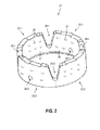
- FIG. 2 shows a first embodiment of a drill ring 21 according to the invention , which has been composed of four ring sections.
- the ring sections can be subdivided into two first ring sections 22.1, 22.2 and two second ring sections 23.1, 23.2 , which are arranged alternately one behind the other along a circumferential direction of the drill ring 21.
- the first ring sections 22.1, 22.2 consist of a first powder mixture 24 and first diamond particles 25
- the second ring sections 23.1, 23.2 consist of a second powder mixture 26 and second diamond particles 27.
- the drill ring 21 Between the ring sections 22.1, 23.1, 22.2, 23.2 four water slots 28.1, 28.2, 28.3, 28.4 are formed, through which a cooling liquid is transported to the processing site.
- the water slots 28.1-28.4 extend over a height of about 2/3 of the total height
- the drill ring 21 additionally has two holes 29.1, 29.2 , is transported via the cooling liquid to the processing site.
- FIGS. 3A-D show the production of the drill ring 21 of the FIG. 2 of two first green parts 31 and two second green parts 32 (FIG. FIG. 3A ), which are formed into the first ring sections 22.1, 22.2 and second ring sections 23.1, 23.2 ( FIG. 3B ).
- the ring sections are arranged alternately one behind the other along the circumferential direction of the drill ring 21 ( FIG. 3C ) and sintered under temperature and pressure into a closed drill ring (FIG. 4D).
- FIG. 3A shows the first green part 31, which is composed of the first powder mixture 24 and the first diamond particles 25, and the second green part 32, which is composed of the second powder mixture 26 and the second diamond particles 27.
- the first diamond particles 25 are enveloped by the first powder mixture 24 and form first encapsulated diamond particles 33 and the second diamond particles 27 are enveloped by the second powder mixture 26 and form second encapsulated diamond particles 34.
- the base of the green parts 31, 32 is hexagonal and consists of a rectangle 35 and an adjacent isosceles trapezium 36. In the region of the trapezoidal legs, the water slots 28.1-28.4 are formed during sintering by additional pressure, is transported via the cooling liquid to the processing site.
- FIG. 3B shows the first ring portion 22, which consists of the first green part 31 of FIG. 3A was generated under pressure, and the second ring portion 23, which consists of the second green part 32 of FIG. 3A was generated under pressure.
- the inner sides 37 of the ring sections 22, 23 have a concave curvature, the opposite outer sides 38 a convex curvature.
- the first ring portion 22 has first and second side edges 41, 42 , which are connected to a first and second side edge 43, 44 of the second ring portion 23 during sintering.
- first side edge 41 of the first ring portion 22 with the second side edge 44 of the second ring portion 23 and the second side edge 42 of the first ring portion 22 with the first side edge 43 of the second ring portion 23 are connected.
- drilling ring 21 with two first and second ring sections 22.1, 22.2, 23.1, 23.2 respectively the first and second side edges of the adjacent ring sections are connected to each other.
- FIG. 3C shows the first and second ring portions 22.1, 22.2, 23.1, 23.2, which are arranged along the circumferential direction of the drill ring 21 in a row and with the side edges 41, 42, 43, 44 adjacent to each other.
- the ring sections 22.1, 23.1, 22.2, 23.2 form a closed drill ring and are in the in FIG. 3C shown arrangement further processed in a hot press.
- FIG. 3D shows the drill ring after hot pressing.
- the ring sections 22.1, 23.1, 22.2, 23.2 subjected to a temperature and pressure.
- the effect of the temperature ensures that the powder mixture 24, 26 is sintered in the ring sections and the ring sections 22.1, 23.1, 22.2, 23.2 are connected to one another at the side edges 41, 42, 43, 44.
- pressure in the axial direction a compression of the ring sections, which leads to a compression of the ring sections.
- the hot pressing takes place in a die, which determines the final shape of the drill ring 21.
- a drill ring is constructed in the process of the invention from several green parts, which are formed into ring sections and sintered into a closed drill ring; polygonal bases are suitable as geometry for the green parts.
- FIGS. 4A-C 5 show green parts 51 with a rectangular base (FIG. 5A), green parts 52 with a pentagonal base (FIG. 5B) and green parts 53 with a hexagonal base (FIG. 5C).
- the rectangular base 54 of the green parts 51 represents the simplest geometry to produce drill rings of several ring sections.
- three equal green parts 51.1, 51.2, 51.3 are used to make a closed drill ring.
- the pentagonal base of the green parts 52 can be divided into a rectangle 55 and a trapezium 56 with two right interior angles.
- a water slot 57 is produced during sintering with the adjacent ring section.
- a number of n water slots 57 are produced in a drill ring having 2n, n.gtoreq.1 ring sections.
- the hexagonal base of the green parts 53 can be divided into a rectangle 58 and an isosceles trapezium 59 .
- water slots 60 are produced during sintering with the adjacent ring sections.
- a number of n water slots 60 is produced in a drill ring with n, n ⁇ 2 ring sections.
Abstract
Verfahren zur Herstellung eines Bohrringes (21) für eine Kernbohrkrone, mit den Schritten: ª mindestens zwei Grünteile werden aus eingekapselten Diamantpartikeln aufgebaut, wobei Diamantpartikel von einem Pulvergemisch umhüllt sind, ª die Grünteile werden unter Druckeinwirkung zu Ringabschnitten (22.1, 22.2, 23.1, 23.2) umgeformt und ª die Ringabschnitte (22.1, 22.2, 23.1, 23.2) werden ringförmig zusammengesetzt und unter Temperatureinwirkung zu einem geschlossenen Bohrring (21) gesintert.Method for producing a drill ring (21) for a core drill bit, with the steps: –ª at least two green parts are made up of encapsulated diamond particles, with diamond particles encased in a powder mixture, –ª the green parts are formed into ring sections (22.1, 22.2, 23.1, 23.2) under the action of pressure and - The ring sections (22.1, 22.2, 23.1, 23.2) are put together in a ring and sintered under the action of temperature to form a closed drill ring (21).
Description
Die vorliegende Erfindung betrifft einen Bohrring für eine Kernbohrkrone gemäß dem Oberbegriff des Anspruchs 1 sowie ein Verfahren zur Herstellung eines Bohrringes gemäß dem Oberbegriff des Anspruchs 9.The present invention relates to a drill ring for a core bit according to the preamble of
Bei Diamantwerkzeugen, die als Kernbohrkronen ausgebildet sind, wird zwischen Kernbohrkronen mit einem geschlossenen Bohrring und segmentierten Kernbohrkronen mit einzelnen Schneidsegmenten unterschieden. Kernbohrkronen bestehen aus einem Bearbeitungsabschnitt, einem zylinderförmigen Bohrschaft und einem Aufnahmeabschnitt mit Einsteckende. Die Kernbohrkrone wird über das Einsteckende in der Werkzeugaufnahme eines Kernbohrgerätes befestigt und im Bohrbetrieb vom Kernbohrgerät um eine Drehachse angetrieben.For diamond tools, which are designed as core drill bits, a distinction is made between core drill bits with a closed drill ring and segmented core drill bits with individual cutting segments. Core bits consist of a machining section, a cylindrical drill shaft and a receiving section with insertion end. The core bit is fastened via the insertion end in the tool holder of a core drilling machine and driven in drilling operation by the core drilling machine about an axis of rotation.
Geschlossene Bohrringe werden aus einem Pulvergemisch mit statistisch verteilten Diamantpartikeln hergestellt. Das Pulvergemisch wird in eine Werkzeugform gefüllt und zu einem Grünteil gepresst; das Grünteil wird unter Temperatur- und Druckeinwirkung zu einem geschlossenen Bohrring gesintert.Closed drill rings are manufactured from a powder mixture with randomly distributed diamond particles. The powder mixture is filled into a mold and pressed into a green part; the green part is sintered under temperature and pressure to form a closed drill ring.
Bei der Herstellung von Schneidsegmenten für segmentierte Kernbohrkronen haben sich im Profibereich Verfahren etabliert, bei denen die Schneidsegmente als Grünteile aus eingekapselten Diamantpartikeln aufgebaut werden. Einzelne Diamantpartikel sind von einem Pulvergemisch umhüllt und bilden die eingekapselten Diamantpartikel. Die eingekapselten Diamantpartikel werden in eine Werkzeugform gefüllt und zu einem Grünteil gepresst; die Grünteile werden anschließend unter Temperatur- und Druckeinwirkung zu fertigen Schneidsegmenten gesintert.In the production of cutting segments for segmented core drill bits, processes have been established in the professional sector in which the cutting segments are constructed as green parts from encapsulated diamond particles. Individual diamond particles are surrounded by a powder mixture and form the encapsulated diamond particles. The encapsulated diamond particles are filled into a mold and pressed into a green part; the green parts are then sintered under temperature and pressure to produce finished cutting segments.
Die Aufgabe der vorliegenden Erfindung besteht darin, die Technologie der eingekapselten Diamantpartikel auf geschlossene Bohrringe anzuwenden und die Bearbeitungsqualität, die mit den so hergestellten Bohrringen erreichbar ist, gegenüber Bohrringen mit statistisch verteilten Diamantpartikeln zu erhöhen.The object of the present invention is to apply the technology of the encapsulated diamond particles to closed drill rings and the machining quality, the achievable with the drilling rings thus produced, to increase compared to drill rings with randomly distributed diamond particles.
Diese Aufgabe wird bei dem eingangs genannten Bohrring für eine Kernbohrkrone erfindungsgemäß durch die Merkmale des unabhängigen Anspruchs 1 und bei dem eingangs genannten Verfahren zur Herstellung eines Bohrringes durch die Merkmale des unabhängigen Anspruchs 9 gelöst. Vorteilhafte Weiterbildungen sind in den abhängigen Ansprüchen angegeben.This object is achieved in the above-mentioned drill ring for a core bit according to the invention by the features of
Erfindungsgemäß ist beim Bohrring vorgesehen, dass die Ringabschnitte an den Seitenkanten miteinander verbunden sind. Der Bohrring ist aus mindestens zwei Ringabschnitten aufgebaut, die aus einem gesinterten Pulvergemisch und Diamantpartikeln bestehen. Dabei wird der Bohrring nicht als geschlossener Bohrring aufgebaut, sondern wird aus zwei oder mehr Ringabschnitten zusammengesetzt, die an den Seitenkanten miteinander verbunden sind.According to the invention, it is provided in the drill ring that the ring sections are connected to one another at the side edges. The drill ring is composed of at least two ring sections consisting of a sintered powder mixture and diamond particles. The drill ring is not constructed as a closed drill ring, but is composed of two or more ring sections, which are connected to each other at the side edges.
In einer bevorzugten Variante umfasst der Bohrring eine Anzahl von n, n ≥ 1 ersten Ringabschnitten und n zweiten Ringabschnitten, wobei die ersten und zweiten Ringabschnitte entlang einer Umfangsrichtung des Bohrringes abwechselnd hintereinander angeordnet sind. Der Aufbau des Bohrringes aus ersten und zweiten Ringabschnitten ermöglicht die Anpassung an unterschiedliche zu bearbeitende Untergründe. Beim Kernbohren in Betonwerkstoffe mit eingebetteten Armierungseisen, die auch als armierte Betonwerkstoffe bezeichnet werden, trifft ein Bohrring beispielsweise auf unterschiedliche Untergründe in Form von Beton und Armierungseisen.In a preferred variant, the drill ring comprises a number of n, n ≥ 1 first ring sections and n second ring sections, wherein the first and second ring sections along a circumferential direction of the drill ring are arranged alternately one behind the other. The structure of the drill ring of first and second ring sections allows adaptation to different substrates to be machined. When drilling cores in concrete materials with embedded reinforcing bars, which are also referred to as reinforced concrete materials, a drill ring meets, for example, different substrates in the form of concrete and reinforcing iron.
Besonders bevorzugt sind die ersten Ringabschnitte aus einem gesinterten ersten Pulvergemisch und ersten Diamantpartikeln aufgebaut und die zweiten Ringabschnitte sind aus einem gesinterten zweiten Pulvergemisch und zweiten Diamantpartikeln aufgebaut. Die Eigenschaften der ersten Ringabschnitte können an einen ersten Untergrund, beispielsweise Beton, und die Eigenschaften der zweiten Ringabschnitte an einen zweiten Untergrund, beispielsweise Armierungseisen, angepasst werden. Die Eigenschaften der Ringabschnitte lassen sich über das Pulvergemisch und die Diamantpartikel einstellen. Bei den Diamantpartikeln können der mittlere Diamantdurchmesser, die Diamantverteilung und die Anzahl an Diamantpartikeln verändert werden.The first ring sections are particularly preferably constructed from a sintered first powder mixture and first diamond particles, and the second ring sections are constructed from a sintered second powder mixture and second diamond particles. The properties of the first ring sections can be adapted to a first ground, for example concrete, and the properties of the second ring sections to a second ground, for example reinforcing iron. The properties of the ring sections can be adjusted via the powder mixture and the diamond particles. For the diamond particles, the mean diamond diameter, the diamond distribution and the number of diamond particles can be changed.
Besonders bevorzugt stimmen das erste Pulvergemisch der ersten Ringabschnitte und das zweite Pulvergemisch der zweiten Ringabschnitte überein. Besonders bevorzugt weisen die ersten Diamantpartikel der ersten Ringabschnitte und die zweiten Diamantpartikel der zweiten Ringabschnitte die gleiche Diamantverteilung und den gleichen mittleren Diamantdurchmesser auf. Durch die Verwendung des gleichen Pulvergemisches und der gleichen Diamantpartikel für die ersten und zweiten Ringabschnitte kann der apparative Aufwand bei der Herstellung des Bohrringes reduziert werden; es werden nur ein Pulvergemisch und eine Sorte an Diamantpartikeln benötigt.Particularly preferably, the first powder mixture of the first ring sections and the second powder mixture of the second ring sections coincide. Particularly preferably, the first diamond particles of the first ring sections and the second diamond particles of the second ring sections have the same diamond distribution and the same mean diamond diameter. By using the same powder mixture and the same diamond particles for the first and second ring sections of the apparatus required in the production of the drill ring can be reduced; only one powder mixture and one kind of diamond particles are needed.
In einer bevorzugten Ausführung ist zwischen den Ringabschnitten mindestens ein Wasserschlitz vorgesehen. Während der Bearbeitung mit dem Bohrring muss Kühlflüssigkeit an die Bearbeitungsstelle transportiert werden; die Kühlflüssigkeit strömt über die Wasserschlitze an die Bearbeitungsstelle und sorgt für eine ausreichende Kühlung des Bohrringes.In a preferred embodiment, at least one water slot is provided between the ring sections. During machining with the drill ring, coolant must be transported to the processing site; the coolant flows over the water slots to the processing point and ensures sufficient cooling of the drill ring.
Besonders bevorzugt erstreckt sich der mindestens eine Wasserschlitz über eine Höhe zwischen 1/3 und 5/6 der Gesamthöhe des Bohrringes. Bei Bohrringen, die mit dem Bohrschaft verschweißt werden, wird der Anbindungsbereich ohne Diamanten aufgebaut und ist für die Bearbeitung ungeeignet. Für die Bearbeitung von Untergründen eignet sich die mit Diamantpartikeln versehene Matrixzone, die ca. 5/6 der Gesamthöhe des Bohrringes darstellt.Particularly preferably, the at least one water slot extends over a height between 1/3 and 5/6 of the overall height of the drill ring. For drill rings that are welded to the drill shank, the connection area is set up without diamonds and is unsuitable for machining. The diamond-coated matrix zone, which is approximately 5/6 of the overall height of the drill ring, is suitable for working on substrates.
Besonders bevorzugt wird die Höhe des mindestens einen Wasserschlitzes auf 2/3 der Gesamthöhe des Bohrringes eingestellt. Bei einem Anteil von 2/3 der Gesamthöhe kann eine ausreichende Festigkeit des fertigen Bohrringes sichergestellt werden. Während der Bearbeitung mit dem Bohrring muss Kühlflüssigkeit an die Bearbeitungsstelle transportiert werden; daher werden die Wasserschlitze im Bohrring so lang wie möglich ausgebildet.Particularly preferably, the height of the at least one water slot is set to 2/3 of the total height of the drill ring. With a share of 2/3 of the total height sufficient strength of the finished drill ring can be ensured. During machining with the drill ring, coolant must be transported to the processing site; Therefore, the water slots are formed in the drill ring as long as possible.
Besonders bevorzugt weisen die Ringabschnitte eine oder mehrere Bohrungen auf, die die Innenseite und Außenseite des Bohrringes verbinden. Dabei ist die Bohrung besonders bevorzugt zumindest teilweise unterhalb des mindestens einen Wasserschlitzes angeordnet. Die zusätzliche Bohrung stellt eine ausreichende Kühlung des Bohrringes sicher, wenn der mindestens eine Wasserschlitz abgetragen ist.Particularly preferably, the ring sections on one or more holes, which connect the inside and outside of the drill ring. In this case, the bore is particularly preferably arranged at least partially below the at least one water slot. The additional hole ensures adequate cooling of the drill ring when the at least one water slot is removed.
Das erfindungsgemäße Verfahren zur Herstellung eines geschlossenen Bohrringes umfasst die Schritte:
- ▪ mindestens zwei Grünteile werden aus eingekapselten Diamantpartikeln aufgebaut, wobei Diamantpartikel von einem Pulvergemisch umhüllt sind,
- ▪ die Grünteile werden unter Druckeinwirkung zu Ringabschnitten umgeformt und
- ▪ die Ringabschnitte werden ringförmig zusammengesetzt und unter Temperatureinwirkung zu einem geschlossenen Bohrring gesintert.
- ▪ at least two green parts are built up from encapsulated diamond particles, whereby diamond particles are enveloped by a powder mixture,
- ▪ the green parts are converted under pressure to ring sections and
- ▪ The ring sections are assembled in a ring shape and sintered under the influence of temperature to form a closed drill ring.
Das erfindungsgemäße Verfahren umfasst drei Verfahrensabschnitte, die unterschiedliche Technologien nutzen. Der Bohrring wird beim erfindungsgemäßen Verfahren nicht als geschlossener Bohrring aufgebaut, sondern wird aus zwei oder mehr Ringabschnitten zusammengesetzt, die durch Sintern verbunden werden.The method according to the invention comprises three process sections which use different technologies. The drill ring is not constructed in the method according to the invention as a closed drill ring, but is composed of two or more ring sections, which are connected by sintering.
Im ersten Verfahrensabschnitt werden mehrere Grünteile aus eingekapselten Diamantpartikeln aufgebaut, wobei Diamantpartikel von einem Pulvergemisch umhüllt sind und die eingekapselten Diamantpartikel bilden. Unter dem Begriff "Pulvergemisch" werden feinkörnige Pulvermischungen und granulierte Pulvermischungen zusammengefasst. Als Pulvergemisch können Eisen-, Kobalt- und/oder Bronzepulver verwendet werden; durch Zumischen von Zusätzen, wie beispielsweise Wolframkarbid, können die Eigenschaften der Bohrringe (Verschleißwiderstand, Lebensdauer, Schnittfreudigkeit) beeinflusst werden. Außerdem hat die Zusammensetzung des Pulvergemisches Einfluss auf die Sintertemperatur. Unter dem Begriff "Diamantpartikel" werden einzelne Diamantpartikel und beschichtete Diamantpartikel zusammengefasst.In the first part of the process, several green parts are built up from encapsulated diamond particles, wherein diamond particles are enveloped by a powder mixture and form the encapsulated diamond particles. The term "powder mixture" includes fine-grained powder mixtures and granulated powder mixtures. As a powder mixture, iron, cobalt and / or bronze powders can be used; By mixing in additives, such as tungsten carbide, the properties of the drill rings (wear resistance, durability, cutting ability) can be influenced. In addition, the composition of the powder mixture has an influence on the sintering temperature. The term "diamond particles" is taken to mean individual diamond particles and coated diamond particles.
Die Grünteile weisen die geometrische Form eines geraden Prismas mit einer mehreckigen Grundfläche auf. Die prismenförmigen Grünteile werden im zweiten Verfahrensabschnitt unter Druckeinwirkung zu Ringabschnitten umgeformt. Das Umformen der Grünteile findet bei Temperaturen statt, die unterhalb der Schmelztemperatur des Pulvergemisches liegen. Im dritten Verfahrensabschnitt werden die Ringabschnitte ringförmig zusammengesetzt und unter Temperatureinwirkung zu einem geschlossenen Bohrring gesintert. Beim Sintern der Ringabschnitte erfolgen zum einen eine Verdichtung der einzelnen Ringabschnitte und zum anderen eine Verbindung zwischen benachbarten Ringabschnitten.The green parts have the geometric shape of a straight prism with a polygonal base. The prismatic green parts are formed in the second process section under pressure to form ring sections. The forming of the green parts takes place at temperatures which are below the melting temperature of the powder mixture. In the third process section, the ring sections are assembled in a ring and sintered under the influence of temperature to form a closed drill ring. When sintering the ring sections done on the one hand, a compression of the individual ring sections and on the other hand, a connection between adjacent ring sections.
Als Umformverfahren eignen sich Kaltpressen, Warmpressen sowie vergleichbare Verfahren. Beim Kaltpressen wird ein Grünteil unter einem hohen Druck in die vorgegebene Form gebracht. In einer Kaltpresse erwärmt der Werkstoff sich zwar, allerdings findet die Umformung in einem Temperaturbereich statt, in dem keine Rekristallisation auftritt; der Werkstoff verformt sich, ohne dass die Festigkeit deutlich abnimmt. Beim Warmpressen, das auch als Gesenkschmieden bezeichnet wird, wird ein Grünteil unter einem hohen Druck und dem Zusatz von Wärme in seine endgültige Form gebracht. Zusätzlich zur Form verändert das Schmiedestück seine Materialstruktur; es wird fester und erhält dadurch ein dichteres Gefüge und eine homogene Oberfläche.Cold forming, hot pressing and similar processes are suitable as forming processes. In cold pressing, a green part is brought under a high pressure in the predetermined shape. In a cold press, the material is indeed heated, but the transformation takes place in a temperature range in which no recrystallization occurs; The material deforms without the strength decreasing significantly. In hot pressing, which is also referred to as drop forging, a green part is brought under its high pressure and the addition of heat in its final form. In addition to the shape, the forging changes its material structure; it gets stronger and thus gets a denser texture and a homogeneous surface.
Sintern ist ein Verfahren zur Herstellung von Werkstoffen, bei dem ein Pulver oder ein Grünteil (gepresstes Pulver) auf Temperaturen unterhalb der Schmelztemperatur erhitzt werden, um die Festigkeit durch Verbinden der einzelnen Pulverpartikel zu erhöhen. Der Sintervorgang läuft in drei Stadien ab, in denen sich die Porosität und das Volumen des Grünteils deutlich verringern. Im ersten Stadium des Sinterns erfolgt lediglich eine Verdichtung des Grünteils, wohingegen sich im zweiten Stadium die offene Porosität deutlich verringert. Die Festigkeit der Sinterkörper beruht auf den, im dritten Stadium gebildeten Sinterverbindungen (Anschmelzungen zwischen den Pulverpartikeln), die durch Oberflächendiffusion zwischen den Pulverpartikeln entstehen. Heißpressen ist ein spezielles Sinterverfahren, bei dem neben Temperatur auch äußerer Druck aufgewendet wird.Sintering is a process for the production of materials in which a powder or a green part (pressed powder) are heated to temperatures below the melting temperature in order to increase the strength by bonding the individual powder particles. The sintering process takes place in three stages, in which the porosity and the volume of the green part are significantly reduced. In the first stage of sintering, only a densification of the green part takes place, whereas in the second stage the open porosity is significantly reduced. The strength of the sintered bodies is based on the sintering compounds formed in the third stage (deposits between the powder particles), which are due to surface diffusion between arise the powder particles. Hot pressing is a special sintering process that uses external pressure in addition to temperature.
In einer bevorzugten Variante wird der Bohrring aus einer Anzahl von n, n ≥ 1 ersten Grünteilen, die zu ersten Ringabschnitten umgeformt werden, und n zweiten Grünteilen, die zu zweiten Ringabschnitten umgeformt werden, aufgebaut, wobei die ersten und zweiten Ringabschnitte entlang einer Umfangsrichtung des Bohrringes abwechselnd hintereinander angeordnet werden. Die Herstellung des Bohrringes aus ersten und zweiten Grünteilen ermöglicht die Anpassung des Bohrringes an unterschiedliche zu bearbeitende Untergründe, beispielsweise an Beton und Armierungseisen in armierten Betonwerkstoffen.In a preferred variant, the drill ring is constructed from a number of n, n ≥ 1 first green parts, which are formed into first ring sections, and n second green parts, which are formed into second ring sections, wherein the first and second ring sections along a circumferential direction of Drill ring are arranged alternately one behind the other. The production of the drill ring from first and second green parts allows the adaptation of the drill ring to different substrates to be machined, for example, to concrete and reinforcing bars in reinforced concrete materials.
Besonders bevorzugt werden die ersten Grünteile aus eingekapselten ersten Diamantpartikeln, die ein erstes Pulvergemisch und erste Diamantpartikel enthalten, hergestellt und die zweiten Grünteile werden aus eingekapselten zweiten Diamantpartikeln, die ein zweites Pulvergemisch und zweite Diamantpartikel enthalten, hergestellt. Die Anpassung des Bohrringes an den zu bearbeitenden Untergrund kann über die Auswahl des Pulvergemisches und die Auswahl der Diamantpartikel erfolgen. Beim Pulvergemisch kann die Zusammensetzung der Werkstoffe variiert werden; bei den Diamantpartikeln können der mittlere Diamantdurchmesser, die Diamantverteilung und die Anzahl der Diamantpartikel variiert werden.More preferably, the first green parts are made from encapsulated first diamond particles containing a first powder mixture and first diamond particles, and the second green parts are made from encapsulated second diamond particles containing a second powder mixture and second diamond particles. The adjustment of the drill ring to the substrate to be processed can be done by selecting the powder mixture and the choice of diamond particles. With the powder mixture, the composition of the materials can be varied; For the diamond particles, the mean diamond diameter, the diamond distribution and the number of diamond particles can be varied.
In einer alternativen Variante wird der Bohrring aus einer Anzahl von n ≥ 2 gleichen Grünteilen aufgebaut, wobei die Grünteile zu Ringabschnitten umgeformt und entlang einer Umfangsrichtung des Bohrringes hintereinander angeordnet werden. Durch die Verwendung von gleichen Grünteilen kann der apparative Aufwand beim Aufbau der Grünteile reduziert werden; es werden nur ein Pulvergemisch und eine Sorte an Diamantpartikeln benötigt.In an alternative variant, the drill ring is constructed from a number of n ≥ 2 equal green parts, wherein the green parts are formed into ring sections and arranged one behind the other along a circumferential direction of the drill ring. By using the same green parts of equipment costs can be reduced in the construction of the green parts; only one powder mixture and one kind of diamond particles are needed.
Die Grünteile weisen die geometrische Form eines geraden Prismas mit einer mehreckigen Grundfläche auf. Als mehreckige Grundflächen eignen sich rechteckige Grundflächen, fünfeckige Grundflächen und sechseckige Grundflächen.The green parts have the geometric shape of a straight prism with a polygonal base. As polygonal bases are rectangular bases, pentagonal bases and hexagonal bases.
In einer ersten Variante werden die Grünteile mit rechteckigen Grundflächen aufgebaut. Die rechteckige Grundfläche stellt die einfachste Geometrie dar, um Bohrringe aus mehreren Ringabschnitten herzustellen. Die Ringabschnitte werden an den Seitenkanten mit den benachbarten Ringabschnitten verbunden.In a first variant, the green parts are constructed with rectangular bases. The rectangular base is the simplest geometry to make drill rings from multiple ring sections. The ring sections are connected at the side edges with the adjacent ring sections.
In einer zweiten Variante werden die Grünteile mit fünfeckigen Grundflächen aufgebaut, wobei die Grundflächen ein Rechteck und ein Trapez mit zwei rechten Innenwinkeln aufweisen. Im Bereich des geneigten Trapezschenkels wird beim Sintern mit dem benachbarten Ringabschnitt ein Wasserschlitz erzeugt. Mit einer solchen fünfeckigen Grundfläche wird bei einem Bohrring mit 2n, n ≥ 1 Ringabschnitten eine Anzahl von n Wasserschlitzen erzeugt.In a second variant, the green parts are constructed with pentagonal bases, the bases have a rectangle and a trapezoid with two right interior angles. In the area of the inclined trapezoid leg, a water slot is created during sintering with the adjacent ring section. With such a pentagonal base area, a number of n water slots is produced in a drill ring with 2n, n.gtoreq.1 ring sections.
In einer dritten Variante werden die Grünteile mit sechseckigen Grundflächen aufgebaut, wobei die Grundflächen ein Rechteck und ein gleichschenkliges Trapez aufweisen. Im Bereich der geneigten Trapezschenkel werden beim Sintern mit den benachbarten Ringabschnitten Wasserschlitze erzeugt. Mit einer solchen sechseckigen Grundfläche wird bei einem Bohrring mit n, n ≥ 2 Ringabschnitten eine Anzahl von n Wasserschlitzen erzeugt.In a third variant, the green parts are constructed with hexagonal bases, the bases have a rectangle and an isosceles trapezoid. In the area of the inclined trapezoidal legs, water slots are created during sintering with the adjacent ring sections. With such a hexagonal base surface, a number of n water slots is produced in a drill ring with n, n ≥ 2 ring sections.
In einer bevorzugten Weiterentwicklung werden die Ringabschnitte beim Sintern einer Temperatur- und Druckeinwirkung unterzogen. Bei Sinterverfahren mit Temperatur- und Druckeinwirkung, wie dem Heißpressen, läuft das Sintern schneller und bei niedrigerer Temperatur ab als bei Sinterverfahren ohne Druckeinwirkung, wie dem freien Sintern. Da thermische Diamantschädigungen bereits bei 600 °C auftreten, kann eine niedrigere Sintertemperatur ein qualitativer Vorteil sein.In a preferred development, the ring sections are subjected to a temperature and pressure effect during sintering. In sintering processes with temperature and pressure, such as hot pressing, the sintering proceeds faster and at a lower temperature than in sintering without pressure, such as free sintering. Since thermal diamond damage already occurs at 600 ° C, a lower sintering temperature can be a qualitative advantage.
Besonders bevorzugt werden die Ringabschnitte durch die Druckeinwirkung beim Sintern einer zusätzlichen äußeren Formgebung unterzogen. Für die Bearbeitung verschiedener Untergründe haben sich spezielle Dachformen als geeignet erwiesen. Diese Dachformen können durch Druckeinwirkung beim Sintern erzeugt werden.Particularly preferably, the ring sections are subjected to an additional external shaping by the pressure effect during sintering. For the treatment of different substrates, special roof forms have proven to be suitable. These roof shapes can be generated by pressure during sintering.
Ausführungsbeispiele der Erfindung werden nachfolgend anhand der Zeichnung beschrieben. Diese soll die Ausführungsbeispiele nicht notwendigerweise maßstäblich darstellen, vielmehr ist die Zeichnung, wo zur Erläuterung dienlich, in schematischer und/oder leicht verzerrter Form ausgeführt. Im Hinblick auf Ergänzungen der aus der Zeichnung unmittelbar erkennbaren Lehren wird auf den einschlägigen Stand der Technik verwiesen. Dabei ist zu berücksichtigen, dass vielfältige Modifikationen und Änderungen betreffend die Form und das Detail einer Ausführungsform vorgenommen werden können, ohne von der allgemeinen Idee der Erfindung abzuweichen. Die in der Beschreibung, der Zeichnung sowie den Ansprüchen offenbarten Merkmale der Erfindung können sowohl einzeln für sich als auch in beliebiger Kombination für die Weiterbildung der Erfindung wesentlich sein. Zudem fallen in den Rahmen der Erfindung alle Kombinationen aus zumindest zwei der in der Beschreibung, der Zeichnung und/oder den Ansprüchen offenbarten Merkmale. Die allgemeine Idee der Erfindung ist nicht beschränkt auf die exakte Form oder das Detail der im Folgenden gezeigten und beschriebenen bevorzugten Ausführungsform oder beschränkt auf einen Gegenstand, der eingeschränkt wäre im Vergleich zu dem in den Ansprüchen beanspruchten Gegenstand. Bei gegebenen Bemessungsbereichen sollen auch innerhalb der genannten Grenzen liegende Werte als Grenzwerte offenbart und beliebig einsetzbar und beanspruchbar sein. Der Einfachheit halber sind nachfolgend für identische oder ähnliche Teile oder Teile mit identischer oder ähnlicher Funktion gleiche Bezugszeichen verwendet.Embodiments of the invention are described below with reference to the drawing. This is not necessarily to scale the embodiments, but the drawing, where appropriate for explanation, executed in a schematic and / or slightly distorted form. With regard to additions to the teachings directly recognizable from the drawing reference is made to the relevant prior art. It should be noted that various modifications and changes may be made in the form and detail of an embodiment without departing from the general idea of the invention. The disclosed in the description, the drawings and the claims features of the invention may be essential both individually and in any combination for the development of the invention. In addition, all combinations of at least two of the features disclosed in the description, the drawings and / or the claims fall within the scope of the invention. The general idea of the invention is not limited to the exact form or detail of the preferred embodiment shown and described below or limited to an article that would be limited in comparison with the subject matter claimed in the claims. For given design ranges, values lying within the specified limits should also be disclosed as limit values and be arbitrarily usable and claimable. For simplicity, the same reference numerals are used below for identical or similar parts or parts with identical or similar function.
Es zeigen:
- FIG. 1
- eine Kernbohrkrone bestehend aus einem Bohrring, einem zylinderförmigen Bohrschaft und einem Aufnahmeabschnitt;
- FIG. 2
- einen erfindungsgemäßen Bohrring mit vier Ringabschnitten und vier Wasserschlitzen zwischen den Ringabschnitten;
- FIGN. 3A-D
- die Herstellung des Bohrringes der
FIG. 2 aus ersten und zweiten Grünteilen mit einer sechseckigen Grundfläche (FIG. 3A ), wobei die Grünteile zu ersten und zweiten Ringabschnitten umgeformt werden (FIG. 3B ), die Ringabschnitte abwechselnd hintereinander angeordnet werden (FIG. 3C ) und zu einem geschlossenen Bohrring gesintert werden (FIG. 3D ); und - FIGN. 4A-C
- Grünteile mit einer rechteckigen Grundfläche (
FIG. 4A ), einer fünfeckigen Grundfläche (FIG. 4B ) und einer sechseckigen Grundfläche (FIG. 4C ).
- FIG. 1
- a core bit consisting of a drill ring, a cylindrical drill shaft and a receiving portion;
- FIG. 2
- a drill ring according to the invention with four ring sections and four water slots between the ring sections;
- FIGS. 3A-D
- the production of the drill ring of
FIG. 2 of first and second green parts with a hexagonal base (FIG. 3A ), wherein the green parts are formed into first and second ring sections (FIG. 3B ), the ring sections are arranged alternately one behind the other (FIG. 3C ) and sintered into a closed drill ring (FIG. 3D ); and - FIGS. 4A-C
- Green parts with a rectangular base (
FIG. 4A ), a pentagonal base (FIG. 4B ) and a hexagonal base (FIG. 4C ).
Der Bohrring 11 ist mit dem Bohrschaft 12 verschweißt, verlötet, verschraubt oder in einer anderen geeigneten Befestigungsart am Bohrschaft 12 befestigt. Um den Bohrring 11 mit dem Bohrschaft 12 verschweißen zu können, muss der Verbindungsbereich zwischen Bohrring 11 und Bohrschaft 12 aus einem schweißbaren Material aufgebaut sein und darf keine Diamanten enthalten, da Diamanten nicht schweißbar sind.The
Zwischen den Ringabschnitten 22.1, 23.1, 22.2, 23.2 sind vier Wasserschlitze 28.1, 28.2, 28.3, 28.4 ausgebildet, über die eine Kühlflüssigkeit an die Bearbeitungsstelle transportiert wird. Die Wasserschlitze 28.1-28.4 erstrecken sich über eine Höhe von ca. 2/3 der Gesamthöhe des Bohrringes 21. Um die Funktionsfähigkeit des Bohrringes 21 auch dann sicherzustellen, wenn die Wasserschlitze 28.1-28.4 abgetragen sind, weist der Bohrring 21 zusätzlich zwei Bohrungen 29.1, 29.2 auf, über die Kühlflüssigkeit an die Bearbeitungsstelle transportiert wird.Between the ring sections 22.1, 23.1, 22.2, 23.2 four water slots 28.1, 28.2, 28.3, 28.4 are formed, through which a cooling liquid is transported to the processing site. The water slots 28.1-28.4 extend over a height of about 2/3 of the total height In order to ensure the functionality of the
Der erste Ringabschnitt 22 weist eine erste und zweite Seitenkante 41, 42 auf, die beim Sintern mit einer ersten und zweiten Seitenkante 43, 44 des zweiten Ringabschnittes 23 verbunden werden. Dabei werden die erste Seitenkante 41 des ersten Ringabschnittes 22 mit der zweiten Seitenkante 44 des zweiten Ringabschnittes 23 und die zweite Seitenkante 42 des ersten Ringabschnittes 22 mit der ersten Seitenkante 43 des zweiten Ringabschnittes 23 verbunden. Beim Bohrring 21 mit zwei ersten und zweiten Ringabschnitten 22.1, 22.2, 23.1, 23.2 werden jeweils die ersten und zweiten Seitenkanten der benachbarten Ringabschnitte miteinander verbunden.The
Ein Bohrring wird beim erfindungsgemäßen Verfahren aus mehreren Grünteilen aufgebaut, die zu Ringabschnitten umgeformt werden und zu einem geschlossenen Bohrring gesintert werden; als Geometrie für die Grünteile eignen sich mehreckige Grundflächen.
Die rechteckige Grundfläche 54 der Grünteile 51 stellt die einfachste Geometrie dar, um Bohrringe aus mehreren Ringabschnitten herzustellen. Im Ausführungsbeispiel der FIG. 5A werden drei gleiche Grünteile 51.1, 51.2, 51.3 verwendet, um einen geschlossenen Bohrring herzustellen.The
Die fünfeckige Grundfläche der Grünteile 52 lässt sich in ein Rechteck 55 und ein Trapez 56 mit zwei rechten Innenwinkeln unterteilen. Im Bereich des geneigten Trapezschenkels wird beim Sintern mit dem benachbarten Ringabschnitt ein Wasserschlitz 57 erzeugt. Mit einer solchen fünfeckigen Grundfläche wird bei einem Bohrring mit 2n, n ≥ 1 Ringabschnitten eine Anzahl von n Wasserschlitzen 57 erzeugt.The pentagonal base of the green parts 52 can be divided into a
Die sechseckige Grundfläche der Grünteile 53 lässt sich in ein Rechteck 58 und ein gleichschenkliges Trapez 59 unterteilen. Im Bereich der geneigten Trapezschenkel werden beim Sintern mit den benachbarten Ringabschnitten Wasserschlitze 60 erzeugt. Mit einer solchen sechseckigen Grundfläche wird bei einem Bohrring mit n, n ≥ 2 Ringabschnitten eine Anzahl von n Wasserschlitzen 60 erzeugt.The hexagonal base of the green parts 53 can be divided into a
Claims (17)
Priority Applications (8)
| Application Number | Priority Date | Filing Date | Title |
|---|---|---|---|
| EP14199723.9A EP3037200A1 (en) | 2014-12-22 | 2014-12-22 | Drill ring for a core drill bit and method for producing a drill ring |
| CN201580072146.XA CN107107220A (en) | 2014-12-22 | 2015-12-22 | Method for the jumping through rings of coring bit and for manufacturing jumping through rings |
| PCT/EP2015/080930 WO2016102539A1 (en) | 2014-12-22 | 2015-12-22 | Drill ring for a core drill bit and method for producing a drill ring |
| KR1020177020373A KR20170093982A (en) | 2014-12-22 | 2015-12-22 | Drill ring for core drill bit and method for manufacturing drill ring |
| AU2015371033A AU2015371033A1 (en) | 2014-12-22 | 2015-12-22 | Drill ring for a core drill bit and method for producing a drill ring |
| RU2017126255A RU2017126255A (en) | 2014-12-22 | 2015-12-22 | Core drill for core drill bit and method of manufacturing a core drill |
| EP15820142.6A EP3237138B1 (en) | 2014-12-22 | 2015-12-22 | Drill ring for a core drill bit and method for producing such a drill ring |
| US15/538,579 US20170368715A1 (en) | 2014-12-22 | 2015-12-22 | Drill Ring for a Core Drill Bit and Method for Producing a Drill Ring |
Applications Claiming Priority (1)
| Application Number | Priority Date | Filing Date | Title |
|---|---|---|---|
| EP14199723.9A EP3037200A1 (en) | 2014-12-22 | 2014-12-22 | Drill ring for a core drill bit and method for producing a drill ring |
Publications (1)
| Publication Number | Publication Date |
|---|---|
| EP3037200A1 true EP3037200A1 (en) | 2016-06-29 |
Family
ID=52292665
Family Applications (2)
| Application Number | Title | Priority Date | Filing Date |
|---|---|---|---|
| EP14199723.9A Withdrawn EP3037200A1 (en) | 2014-12-22 | 2014-12-22 | Drill ring for a core drill bit and method for producing a drill ring |
| EP15820142.6A Active EP3237138B1 (en) | 2014-12-22 | 2015-12-22 | Drill ring for a core drill bit and method for producing such a drill ring |
Family Applications After (1)
| Application Number | Title | Priority Date | Filing Date |
|---|---|---|---|
| EP15820142.6A Active EP3237138B1 (en) | 2014-12-22 | 2015-12-22 | Drill ring for a core drill bit and method for producing such a drill ring |
Country Status (7)
| Country | Link |
|---|---|
| US (1) | US20170368715A1 (en) |
| EP (2) | EP3037200A1 (en) |
| KR (1) | KR20170093982A (en) |
| CN (1) | CN107107220A (en) |
| AU (1) | AU2015371033A1 (en) |
| RU (1) | RU2017126255A (en) |
| WO (1) | WO2016102539A1 (en) |
Families Citing this family (3)
| Publication number | Priority date | Publication date | Assignee | Title |
|---|---|---|---|---|
| EP3305448B1 (en) | 2016-09-23 | 2020-11-04 | Milwaukee Electric Tool Corporation | Hole saw arbor assembly |
| EP3725441A1 (en) | 2017-01-06 | 2020-10-21 | Milwaukee Electric Tool Corporation | Hole saw |
| USD973733S1 (en) | 2017-08-15 | 2022-12-27 | Milwaukee Electric Tool Corporation | Hole saw |
Citations (5)
| Publication number | Priority date | Publication date | Assignee | Title |
|---|---|---|---|---|
| WO1991010750A1 (en) * | 1990-01-12 | 1991-07-25 | Kalevi Antti Bragge | Method for boring flue hole |
| JPH05169307A (en) * | 1991-12-17 | 1993-07-09 | Rasa Kogyo Kk | Core drill |
| JPH0671638A (en) * | 1992-03-02 | 1994-03-15 | Rasa Ind Ltd | Core drill |
| US5316416A (en) * | 1992-09-29 | 1994-05-31 | Ehwa Diamond Ind. Co., Ltd. | Diamond cutting tool for hard articles |
| US20060130823A1 (en) * | 2003-03-06 | 2006-06-22 | Kim Soo K | Gear type machining tip and tool attaching the same thereon |
Family Cites Families (5)
| Publication number | Priority date | Publication date | Assignee | Title |
|---|---|---|---|---|
| JP3370895B2 (en) * | 1997-04-11 | 2003-01-27 | 日本鋼管株式会社 | Disc tool for drilling rolls |
| KR100428947B1 (en) * | 2001-09-28 | 2004-04-29 | 이화다이아몬드공업 주식회사 | Diamond Tool |
| CN2834751Y (en) * | 2005-12-06 | 2006-11-08 | 石家庄博深工具集团有限公司 | Novel diamond grinding head |
| CN101353946A (en) * | 2008-09-11 | 2009-01-28 | 吉林大学 | Diamond core bit capable of reproducing water gap |
| CN201471608U (en) * | 2009-08-11 | 2010-05-19 | 侯家祥 | Environment-friendly dry drilling diamond drill |
-
2014
- 2014-12-22 EP EP14199723.9A patent/EP3037200A1/en not_active Withdrawn
-
2015
- 2015-12-22 RU RU2017126255A patent/RU2017126255A/en not_active Application Discontinuation
- 2015-12-22 WO PCT/EP2015/080930 patent/WO2016102539A1/en active Application Filing
- 2015-12-22 EP EP15820142.6A patent/EP3237138B1/en active Active
- 2015-12-22 US US15/538,579 patent/US20170368715A1/en not_active Abandoned
- 2015-12-22 CN CN201580072146.XA patent/CN107107220A/en active Pending
- 2015-12-22 AU AU2015371033A patent/AU2015371033A1/en not_active Abandoned
- 2015-12-22 KR KR1020177020373A patent/KR20170093982A/en not_active Application Discontinuation
Patent Citations (5)
| Publication number | Priority date | Publication date | Assignee | Title |
|---|---|---|---|---|
| WO1991010750A1 (en) * | 1990-01-12 | 1991-07-25 | Kalevi Antti Bragge | Method for boring flue hole |
| JPH05169307A (en) * | 1991-12-17 | 1993-07-09 | Rasa Kogyo Kk | Core drill |
| JPH0671638A (en) * | 1992-03-02 | 1994-03-15 | Rasa Ind Ltd | Core drill |
| US5316416A (en) * | 1992-09-29 | 1994-05-31 | Ehwa Diamond Ind. Co., Ltd. | Diamond cutting tool for hard articles |
| US20060130823A1 (en) * | 2003-03-06 | 2006-06-22 | Kim Soo K | Gear type machining tip and tool attaching the same thereon |
Also Published As
| Publication number | Publication date |
|---|---|
| RU2017126255A (en) | 2019-01-24 |
| AU2015371033A1 (en) | 2017-07-13 |
| CN107107220A (en) | 2017-08-29 |
| WO2016102539A9 (en) | 2016-08-25 |
| EP3237138B1 (en) | 2019-10-02 |
| RU2017126255A3 (en) | 2019-01-24 |
| US20170368715A1 (en) | 2017-12-28 |
| KR20170093982A (en) | 2017-08-16 |
| WO2016102539A1 (en) | 2016-06-30 |
| EP3237138A1 (en) | 2017-11-01 |
Similar Documents
| Publication | Publication Date | Title |
|---|---|---|
| EP3237164B1 (en) | Drill ring for a core drill bit | |
| WO2020126091A1 (en) | Machining segment for a machining tool | |
| DE2013198A1 (en) | Diamond products and processes and apparatus for their manufacture | |
| WO2016102525A1 (en) | Method for manufacturing a continuous drill ring for a core drill bit | |
| EP3898040A1 (en) | Method for producing a machining segment for the dry machining of concrete materials | |
| EP3674025A1 (en) | Processing segment for dry processing of concrete materials | |
| EP3898041A1 (en) | Method for producing a machining segment for the dry machining of concrete materials | |
| EP3898035A1 (en) | Method for producing a machining segment for the dry machining of concrete materials | |
| EP3898039A1 (en) | Method for producing a green body and method for further processing the green body to form a machining segment for the dry machining of concrete materials | |
| EP3237138B1 (en) | Drill ring for a core drill bit and method for producing such a drill ring | |
| WO2020127636A1 (en) | Method for producing a machining segment for the dry machining of concrete materials | |
| WO2016102523A1 (en) | Method for manufacturing a continuous drill ring for a core drill bit | |
| DE102007044269A1 (en) | Partially ground tool bar made of sintered material | |
| EP3135434B1 (en) | Method for producing a multi-dimensional scalable tool | |
| EP4171849A1 (en) | Method for producing a green body and method for further processing the green body to form a machining segment | |
| EP3928894A1 (en) | Method for producing a green compact and method for processing the green compact into a processing segment | |
| EP4106988B1 (en) | Pressing tool and method for producing a spherical green body | |
| DE10131333A1 (en) | hobs | |
| EP3928895A1 (en) | Method for producing a green compact and method for processing the green compact into a processing segment | |
| EP4171878A1 (en) | Method for producing a green body and method for further processing the green body to form a machining segment | |
| EP3928893A1 (en) | Method for manufacturing a processing segment with a projection of hard material particles on the upper side | |
| EP3928903A1 (en) | Method for manufacturing a machining segment with a projection of hard material particles on the side faces | |
| EP3437761A1 (en) | Method for producing a processing segment for an abrasive machining tool |
Legal Events
| Date | Code | Title | Description |
|---|---|---|---|
| PUAI | Public reference made under article 153(3) epc to a published international application that has entered the european phase |
Free format text: ORIGINAL CODE: 0009012 |
|
| AK | Designated contracting states |
Kind code of ref document: A1 Designated state(s): AL AT BE BG CH CY CZ DE DK EE ES FI FR GB GR HR HU IE IS IT LI LT LU LV MC MK MT NL NO PL PT RO RS SE SI SK SM TR |
|
| AX | Request for extension of the european patent |
Extension state: BA ME |
|
| 17P | Request for examination filed |
Effective date: 20170102 |
|
| RBV | Designated contracting states (corrected) |
Designated state(s): AL AT BE BG CH CY CZ DE DK EE ES FI FR GB GR HR HU IE IS IT LI LT LU LV MC MK MT NL NO PL PT RO RS SE SI SK SM TR |
|
| STAA | Information on the status of an ep patent application or granted ep patent |
Free format text: STATUS: THE APPLICATION IS DEEMED TO BE WITHDRAWN |
|
| 18D | Application deemed to be withdrawn |
Effective date: 20170103 |