EP3037200A1 - Bague de forage pour une couronne de carottage et procédé de fabrication d'une bague de forage - Google Patents
Bague de forage pour une couronne de carottage et procédé de fabrication d'une bague de forage Download PDFInfo
- Publication number
- EP3037200A1 EP3037200A1 EP14199723.9A EP14199723A EP3037200A1 EP 3037200 A1 EP3037200 A1 EP 3037200A1 EP 14199723 A EP14199723 A EP 14199723A EP 3037200 A1 EP3037200 A1 EP 3037200A1
- Authority
- EP
- European Patent Office
- Prior art keywords
- ring
- drill
- ring sections
- diamond particles
- sections
- Prior art date
- Legal status (The legal status is an assumption and is not a legal conclusion. Google has not performed a legal analysis and makes no representation as to the accuracy of the status listed.)
- Withdrawn
Links
Images


Classifications
-
- B—PERFORMING OPERATIONS; TRANSPORTING
- B28—WORKING CEMENT, CLAY, OR STONE
- B28D—WORKING STONE OR STONE-LIKE MATERIALS
- B28D1/00—Working stone or stone-like materials, e.g. brick, concrete or glass, not provided for elsewhere; Machines, devices, tools therefor
- B28D1/14—Working stone or stone-like materials, e.g. brick, concrete or glass, not provided for elsewhere; Machines, devices, tools therefor by boring or drilling
- B28D1/146—Tools therefor
-
- B—PERFORMING OPERATIONS; TRANSPORTING
- B28—WORKING CEMENT, CLAY, OR STONE
- B28D—WORKING STONE OR STONE-LIKE MATERIALS
- B28D1/00—Working stone or stone-like materials, e.g. brick, concrete or glass, not provided for elsewhere; Machines, devices, tools therefor
- B28D1/02—Working stone or stone-like materials, e.g. brick, concrete or glass, not provided for elsewhere; Machines, devices, tools therefor by sawing
- B28D1/04—Working stone or stone-like materials, e.g. brick, concrete or glass, not provided for elsewhere; Machines, devices, tools therefor by sawing with circular or cylindrical saw-blades or saw-discs
- B28D1/041—Working stone or stone-like materials, e.g. brick, concrete or glass, not provided for elsewhere; Machines, devices, tools therefor by sawing with circular or cylindrical saw-blades or saw-discs with cylinder saws, e.g. trepanning; saw cylinders, e.g. having their cutting rim equipped with abrasive particles
-
- B—PERFORMING OPERATIONS; TRANSPORTING
- B23—MACHINE TOOLS; METAL-WORKING NOT OTHERWISE PROVIDED FOR
- B23B—TURNING; BORING
- B23B51/00—Tools for drilling machines
- B23B51/04—Drills for trepanning
- B23B51/042—Drills for trepanning with lubricating or cooling equipment
-
- B—PERFORMING OPERATIONS; TRANSPORTING
- B23—MACHINE TOOLS; METAL-WORKING NOT OTHERWISE PROVIDED FOR
- B23D—PLANING; SLOTTING; SHEARING; BROACHING; SAWING; FILING; SCRAPING; LIKE OPERATIONS FOR WORKING METAL BY REMOVING MATERIAL, NOT OTHERWISE PROVIDED FOR
- B23D61/00—Tools for sawing machines or sawing devices; Clamping devices for these tools
- B23D61/02—Circular saw blades
- B23D61/04—Circular saw blades with inserted saw teeth the teeth being individually inserted
-
- B—PERFORMING OPERATIONS; TRANSPORTING
- B23—MACHINE TOOLS; METAL-WORKING NOT OTHERWISE PROVIDED FOR
- B23D—PLANING; SLOTTING; SHEARING; BROACHING; SAWING; FILING; SCRAPING; LIKE OPERATIONS FOR WORKING METAL BY REMOVING MATERIAL, NOT OTHERWISE PROVIDED FOR
- B23D65/00—Making tools for sawing machines or sawing devices for use in cutting any kind of material
-
- B—PERFORMING OPERATIONS; TRANSPORTING
- B23—MACHINE TOOLS; METAL-WORKING NOT OTHERWISE PROVIDED FOR
- B23P—METAL-WORKING NOT OTHERWISE PROVIDED FOR; COMBINED OPERATIONS; UNIVERSAL MACHINE TOOLS
- B23P15/00—Making specific metal objects by operations not covered by a single other subclass or a group in this subclass
- B23P15/28—Making specific metal objects by operations not covered by a single other subclass or a group in this subclass cutting tools
-
- B—PERFORMING OPERATIONS; TRANSPORTING
- B28—WORKING CEMENT, CLAY, OR STONE
- B28D—WORKING STONE OR STONE-LIKE MATERIALS
- B28D1/00—Working stone or stone-like materials, e.g. brick, concrete or glass, not provided for elsewhere; Machines, devices, tools therefor
- B28D1/02—Working stone or stone-like materials, e.g. brick, concrete or glass, not provided for elsewhere; Machines, devices, tools therefor by sawing
- B28D1/12—Saw-blades or saw-discs specially adapted for working stone
- B28D1/121—Circular saw blades
-
- B—PERFORMING OPERATIONS; TRANSPORTING
- B23—MACHINE TOOLS; METAL-WORKING NOT OTHERWISE PROVIDED FOR
- B23B—TURNING; BORING
- B23B2226/00—Materials of tools or workpieces not comprising a metal
- B23B2226/31—Diamond
-
- B—PERFORMING OPERATIONS; TRANSPORTING
- B23—MACHINE TOOLS; METAL-WORKING NOT OTHERWISE PROVIDED FOR
- B23B—TURNING; BORING
- B23B2250/00—Compensating adverse effects during turning, boring or drilling
- B23B2250/12—Cooling and lubrication
Definitions
- the present invention relates to a drill ring for a core bit according to the preamble of claim 1 and to a method for producing a drill ring according to the preamble of claim 9.
- Core bits consist of a machining section, a cylindrical drill shaft and a receiving section with insertion end.
- the core bit is fastened via the insertion end in the tool holder of a core drilling machine and driven in drilling operation by the core drilling machine about an axis of rotation.
- Closed drill rings are manufactured from a powder mixture with randomly distributed diamond particles.
- the powder mixture is filled into a mold and pressed into a green part; the green part is sintered under temperature and pressure to form a closed drill ring.
- the object of the present invention is to apply the technology of the encapsulated diamond particles to closed drill rings and the machining quality, the achievable with the drilling rings thus produced, to increase compared to drill rings with randomly distributed diamond particles.
- the ring sections are connected to one another at the side edges.
- the drill ring is composed of at least two ring sections consisting of a sintered powder mixture and diamond particles.
- the drill ring is not constructed as a closed drill ring, but is composed of two or more ring sections, which are connected to each other at the side edges.
- the drill ring comprises a number of n, n ⁇ 1 first ring sections and n second ring sections, wherein the first and second ring sections along a circumferential direction of the drill ring are arranged alternately one behind the other.
- the structure of the drill ring of first and second ring sections allows adaptation to different substrates to be machined.
- a drill ring meets, for example, different substrates in the form of concrete and reinforcing iron.
- the first ring sections are particularly preferably constructed from a sintered first powder mixture and first diamond particles
- the second ring sections are constructed from a sintered second powder mixture and second diamond particles.
- the properties of the first ring sections can be adapted to a first ground, for example concrete, and the properties of the second ring sections to a second ground, for example reinforcing iron.
- the properties of the ring sections can be adjusted via the powder mixture and the diamond particles. For the diamond particles, the mean diamond diameter, the diamond distribution and the number of diamond particles can be changed.
- the first powder mixture of the first ring sections and the second powder mixture of the second ring sections coincide.
- the first diamond particles of the first ring sections and the second diamond particles of the second ring sections have the same diamond distribution and the same mean diamond diameter.
- At least one water slot is provided between the ring sections.
- coolant must be transported to the processing site; the coolant flows over the water slots to the processing point and ensures sufficient cooling of the drill ring.
- the at least one water slot extends over a height between 1/3 and 5/6 of the overall height of the drill ring.
- the connection area is set up without diamonds and is unsuitable for machining.
- the diamond-coated matrix zone which is approximately 5/6 of the overall height of the drill ring, is suitable for working on substrates.
- the height of the at least one water slot is set to 2/3 of the total height of the drill ring. With a share of 2/3 of the total height sufficient strength of the finished drill ring can be ensured.
- coolant must be transported to the processing site; Therefore, the water slots are formed in the drill ring as long as possible.
- the ring sections on one or more holes, which connect the inside and outside of the drill ring.
- the bore is particularly preferably arranged at least partially below the at least one water slot. The additional hole ensures adequate cooling of the drill ring when the at least one water slot is removed.
- the method according to the invention comprises three process sections which use different technologies.
- the drill ring is not constructed in the method according to the invention as a closed drill ring, but is composed of two or more ring sections, which are connected by sintering.
- encapsulated diamond particles In the first part of the process, several green parts are built up from encapsulated diamond particles, wherein diamond particles are enveloped by a powder mixture and form the encapsulated diamond particles.
- the term "powder mixture” includes fine-grained powder mixtures and granulated powder mixtures.
- a powder mixture iron, cobalt and / or bronze powders can be used;
- additives such as tungsten carbide
- the properties of the drill rings wear resistance, durability, cutting ability
- the composition of the powder mixture has an influence on the sintering temperature.
- diamond particles is taken to mean individual diamond particles and coated diamond particles.
- the green parts have the geometric shape of a straight prism with a polygonal base.
- the prismatic green parts are formed in the second process section under pressure to form ring sections.
- the forming of the green parts takes place at temperatures which are below the melting temperature of the powder mixture.
- the ring sections are assembled in a ring and sintered under the influence of temperature to form a closed drill ring.
- Cold forming, hot pressing and similar processes are suitable as forming processes.
- cold pressing a green part is brought under a high pressure in the predetermined shape.
- the material is indeed heated, but the transformation takes place in a temperature range in which no recrystallization occurs; The material deforms without the strength decreasing significantly.
- hot pressing which is also referred to as drop forging, a green part is brought under its high pressure and the addition of heat in its final form. In addition to the shape, the forging changes its material structure; it gets stronger and thus gets a denser texture and a homogeneous surface.
- Sintering is a process for the production of materials in which a powder or a green part (pressed powder) are heated to temperatures below the melting temperature in order to increase the strength by bonding the individual powder particles.
- the sintering process takes place in three stages, in which the porosity and the volume of the green part are significantly reduced. In the first stage of sintering, only a densification of the green part takes place, whereas in the second stage the open porosity is significantly reduced.
- the strength of the sintered bodies is based on the sintering compounds formed in the third stage (deposits between the powder particles), which are due to surface diffusion between arise the powder particles.
- Hot pressing is a special sintering process that uses external pressure in addition to temperature.
- the drill ring is constructed from a number of n, n ⁇ 1 first green parts, which are formed into first ring sections, and n second green parts, which are formed into second ring sections, wherein the first and second ring sections along a circumferential direction of Drill ring are arranged alternately one behind the other.
- the production of the drill ring from first and second green parts allows the adaptation of the drill ring to different substrates to be machined, for example, to concrete and reinforcing bars in reinforced concrete materials.
- the first green parts are made from encapsulated first diamond particles containing a first powder mixture and first diamond particles
- the second green parts are made from encapsulated second diamond particles containing a second powder mixture and second diamond particles.
- the adjustment of the drill ring to the substrate to be processed can be done by selecting the powder mixture and the choice of diamond particles.
- the composition of the materials can be varied;
- the mean diamond diameter, the diamond distribution and the number of diamond particles can be varied.
- the drill ring is constructed from a number of n ⁇ 2 equal green parts, wherein the green parts are formed into ring sections and arranged one behind the other along a circumferential direction of the drill ring.
- the green parts have the geometric shape of a straight prism with a polygonal base.
- polygonal bases are rectangular bases, pentagonal bases and hexagonal bases.
- the green parts are constructed with rectangular bases.
- the rectangular base is the simplest geometry to make drill rings from multiple ring sections.
- the ring sections are connected at the side edges with the adjacent ring sections.
- the green parts are constructed with pentagonal bases, the bases have a rectangle and a trapezoid with two right interior angles.
- a water slot is created during sintering with the adjacent ring section.
- a number of n water slots is produced in a drill ring with 2n, n.gtoreq.1 ring sections.
- the green parts are constructed with hexagonal bases, the bases have a rectangle and an isosceles trapezoid. In the area of the inclined trapezoidal legs, water slots are created during sintering with the adjacent ring sections. With such a hexagonal base surface, a number of n water slots is produced in a drill ring with n, n ⁇ 2 ring sections.
- the ring sections are subjected to a temperature and pressure effect during sintering.
- sintering processes with temperature and pressure such as hot pressing
- the sintering proceeds faster and at a lower temperature than in sintering without pressure, such as free sintering. Since thermal diamond damage already occurs at 600 ° C, a lower sintering temperature can be a qualitative advantage.
- the ring sections are subjected to an additional external shaping by the pressure effect during sintering.
- special roof forms have proven to be suitable. These roof shapes can be generated by pressure during sintering.
- FIG. 1 shows a core bit 10 with a drill ring 11, a cylindrical drill shaft 12 and a receiving portion 13 with insertion 14.
- the core bit 10 is attached via the insertion end 14 in the tool holder of a core drill and driven in drilling operation by the core drill in a rotational direction 15 about a rotation axis 16 , wherein the axis of rotation 16 is coaxial with the cylinder axis of the core bit 10.
- the drill ring 11 is welded to the drill shaft 12, soldered, screwed or fastened in another suitable manner of attachment to the drill shaft 12.
- the connection area between the drill ring 11 and the drill shank 12 must be constructed of a weldable material and must not contain diamonds, since diamonds are not weldable.
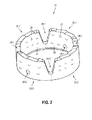
- FIG. 2 shows a first embodiment of a drill ring 21 according to the invention , which has been composed of four ring sections.
- the ring sections can be subdivided into two first ring sections 22.1, 22.2 and two second ring sections 23.1, 23.2 , which are arranged alternately one behind the other along a circumferential direction of the drill ring 21.
- the first ring sections 22.1, 22.2 consist of a first powder mixture 24 and first diamond particles 25
- the second ring sections 23.1, 23.2 consist of a second powder mixture 26 and second diamond particles 27.
- the drill ring 21 Between the ring sections 22.1, 23.1, 22.2, 23.2 four water slots 28.1, 28.2, 28.3, 28.4 are formed, through which a cooling liquid is transported to the processing site.
- the water slots 28.1-28.4 extend over a height of about 2/3 of the total height
- the drill ring 21 additionally has two holes 29.1, 29.2 , is transported via the cooling liquid to the processing site.
- FIGS. 3A-D show the production of the drill ring 21 of the FIG. 2 of two first green parts 31 and two second green parts 32 (FIG. FIG. 3A ), which are formed into the first ring sections 22.1, 22.2 and second ring sections 23.1, 23.2 ( FIG. 3B ).
- the ring sections are arranged alternately one behind the other along the circumferential direction of the drill ring 21 ( FIG. 3C ) and sintered under temperature and pressure into a closed drill ring (FIG. 4D).
- FIG. 3A shows the first green part 31, which is composed of the first powder mixture 24 and the first diamond particles 25, and the second green part 32, which is composed of the second powder mixture 26 and the second diamond particles 27.
- the first diamond particles 25 are enveloped by the first powder mixture 24 and form first encapsulated diamond particles 33 and the second diamond particles 27 are enveloped by the second powder mixture 26 and form second encapsulated diamond particles 34.
- the base of the green parts 31, 32 is hexagonal and consists of a rectangle 35 and an adjacent isosceles trapezium 36. In the region of the trapezoidal legs, the water slots 28.1-28.4 are formed during sintering by additional pressure, is transported via the cooling liquid to the processing site.
- FIG. 3B shows the first ring portion 22, which consists of the first green part 31 of FIG. 3A was generated under pressure, and the second ring portion 23, which consists of the second green part 32 of FIG. 3A was generated under pressure.
- the inner sides 37 of the ring sections 22, 23 have a concave curvature, the opposite outer sides 38 a convex curvature.
- the first ring portion 22 has first and second side edges 41, 42 , which are connected to a first and second side edge 43, 44 of the second ring portion 23 during sintering.
- first side edge 41 of the first ring portion 22 with the second side edge 44 of the second ring portion 23 and the second side edge 42 of the first ring portion 22 with the first side edge 43 of the second ring portion 23 are connected.
- drilling ring 21 with two first and second ring sections 22.1, 22.2, 23.1, 23.2 respectively the first and second side edges of the adjacent ring sections are connected to each other.
- FIG. 3C shows the first and second ring portions 22.1, 22.2, 23.1, 23.2, which are arranged along the circumferential direction of the drill ring 21 in a row and with the side edges 41, 42, 43, 44 adjacent to each other.
- the ring sections 22.1, 23.1, 22.2, 23.2 form a closed drill ring and are in the in FIG. 3C shown arrangement further processed in a hot press.
- FIG. 3D shows the drill ring after hot pressing.
- the ring sections 22.1, 23.1, 22.2, 23.2 subjected to a temperature and pressure.
- the effect of the temperature ensures that the powder mixture 24, 26 is sintered in the ring sections and the ring sections 22.1, 23.1, 22.2, 23.2 are connected to one another at the side edges 41, 42, 43, 44.
- pressure in the axial direction a compression of the ring sections, which leads to a compression of the ring sections.
- the hot pressing takes place in a die, which determines the final shape of the drill ring 21.
- a drill ring is constructed in the process of the invention from several green parts, which are formed into ring sections and sintered into a closed drill ring; polygonal bases are suitable as geometry for the green parts.
- FIGS. 4A-C 5 show green parts 51 with a rectangular base (FIG. 5A), green parts 52 with a pentagonal base (FIG. 5B) and green parts 53 with a hexagonal base (FIG. 5C).
- the rectangular base 54 of the green parts 51 represents the simplest geometry to produce drill rings of several ring sections.
- three equal green parts 51.1, 51.2, 51.3 are used to make a closed drill ring.
- the pentagonal base of the green parts 52 can be divided into a rectangle 55 and a trapezium 56 with two right interior angles.
- a water slot 57 is produced during sintering with the adjacent ring section.
- a number of n water slots 57 are produced in a drill ring having 2n, n.gtoreq.1 ring sections.
- the hexagonal base of the green parts 53 can be divided into a rectangle 58 and an isosceles trapezium 59 .
- water slots 60 are produced during sintering with the adjacent ring sections.
- a number of n water slots 60 is produced in a drill ring with n, n ⁇ 2 ring sections.
Priority Applications (8)
| Application Number | Priority Date | Filing Date | Title |
|---|---|---|---|
| EP14199723.9A EP3037200A1 (fr) | 2014-12-22 | 2014-12-22 | Bague de forage pour une couronne de carottage et procédé de fabrication d'une bague de forage |
| AU2015371033A AU2015371033A1 (en) | 2014-12-22 | 2015-12-22 | Drill ring for a core drill bit and method for producing a drill ring |
| PCT/EP2015/080930 WO2016102539A1 (fr) | 2014-12-22 | 2015-12-22 | Anneau de carottage pour couronne de carottage et procédé de réalisation d'un anneau de carottage |
| RU2017126255A RU2017126255A (ru) | 2014-12-22 | 2015-12-22 | Кольцевое сверло для колонковой сверлильной коронки и способ изготовления кольцевого сверла |
| KR1020177020373A KR20170093982A (ko) | 2014-12-22 | 2015-12-22 | 코어 드릴 비트용 드릴 링 및 드릴 링을 제조하기 위한 방법 |
| EP15820142.6A EP3237138B1 (fr) | 2014-12-22 | 2015-12-22 | Bague de forage pour une couronne de carottage et procédé de fabrication d'une telle bague de forage |
| US15/538,579 US20170368715A1 (en) | 2014-12-22 | 2015-12-22 | Drill Ring for a Core Drill Bit and Method for Producing a Drill Ring |
| CN201580072146.XA CN107107220A (zh) | 2014-12-22 | 2015-12-22 | 用于取芯钻头的钻环以及用于制造钻环的方法 |
Applications Claiming Priority (1)
| Application Number | Priority Date | Filing Date | Title |
|---|---|---|---|
| EP14199723.9A EP3037200A1 (fr) | 2014-12-22 | 2014-12-22 | Bague de forage pour une couronne de carottage et procédé de fabrication d'une bague de forage |
Publications (1)
| Publication Number | Publication Date |
|---|---|
| EP3037200A1 true EP3037200A1 (fr) | 2016-06-29 |
Family
ID=52292665
Family Applications (2)
| Application Number | Title | Priority Date | Filing Date |
|---|---|---|---|
| EP14199723.9A Withdrawn EP3037200A1 (fr) | 2014-12-22 | 2014-12-22 | Bague de forage pour une couronne de carottage et procédé de fabrication d'une bague de forage |
| EP15820142.6A Active EP3237138B1 (fr) | 2014-12-22 | 2015-12-22 | Bague de forage pour une couronne de carottage et procédé de fabrication d'une telle bague de forage |
Family Applications After (1)
| Application Number | Title | Priority Date | Filing Date |
|---|---|---|---|
| EP15820142.6A Active EP3237138B1 (fr) | 2014-12-22 | 2015-12-22 | Bague de forage pour une couronne de carottage et procédé de fabrication d'une telle bague de forage |
Country Status (7)
| Country | Link |
|---|---|
| US (1) | US20170368715A1 (fr) |
| EP (2) | EP3037200A1 (fr) |
| KR (1) | KR20170093982A (fr) |
| CN (1) | CN107107220A (fr) |
| AU (1) | AU2015371033A1 (fr) |
| RU (1) | RU2017126255A (fr) |
| WO (1) | WO2016102539A1 (fr) |
Families Citing this family (3)
| Publication number | Priority date | Publication date | Assignee | Title |
|---|---|---|---|---|
| US10532412B2 (en) | 2016-09-23 | 2020-01-14 | Milwaukee Electric Tool Corporation | Hole saw arbor assembly |
| EP3354385B1 (fr) | 2017-01-06 | 2020-05-27 | Milwaukee Electric Tool Corporation | Scie-cloche |
| USD973733S1 (en) | 2017-08-15 | 2022-12-27 | Milwaukee Electric Tool Corporation | Hole saw |
Citations (5)
| Publication number | Priority date | Publication date | Assignee | Title |
|---|---|---|---|---|
| WO1991010750A1 (fr) * | 1990-01-12 | 1991-07-25 | Kalevi Antti Bragge | Procede de perçage de trous d'evacuation des gaz |
| JPH05169307A (ja) * | 1991-12-17 | 1993-07-09 | Rasa Kogyo Kk | コアドリル |
| JPH0671638A (ja) * | 1992-03-02 | 1994-03-15 | Rasa Ind Ltd | コアドリル |
| US5316416A (en) * | 1992-09-29 | 1994-05-31 | Ehwa Diamond Ind. Co., Ltd. | Diamond cutting tool for hard articles |
| US20060130823A1 (en) * | 2003-03-06 | 2006-06-22 | Kim Soo K | Gear type machining tip and tool attaching the same thereon |
Family Cites Families (5)
| Publication number | Priority date | Publication date | Assignee | Title |
|---|---|---|---|---|
| JP3370895B2 (ja) * | 1997-04-11 | 2003-01-27 | 日本鋼管株式会社 | 孔型ロール改削用ディスクバイト |
| KR100428947B1 (ko) * | 2001-09-28 | 2004-04-29 | 이화다이아몬드공업 주식회사 | 다이아몬드 공구 |
| CN2834751Y (zh) * | 2005-12-06 | 2006-11-08 | 石家庄博深工具集团有限公司 | 新型金刚石钻头 |
| CN101353946A (zh) * | 2008-09-11 | 2009-01-28 | 吉林大学 | 可再生水口的金刚石取芯钻头 |
| CN201471608U (zh) * | 2009-08-11 | 2010-05-19 | 侯家祥 | 一种环保型干钻金刚石钻体 |
-
2014
- 2014-12-22 EP EP14199723.9A patent/EP3037200A1/fr not_active Withdrawn
-
2015
- 2015-12-22 WO PCT/EP2015/080930 patent/WO2016102539A1/fr active Application Filing
- 2015-12-22 KR KR1020177020373A patent/KR20170093982A/ko not_active Application Discontinuation
- 2015-12-22 EP EP15820142.6A patent/EP3237138B1/fr active Active
- 2015-12-22 AU AU2015371033A patent/AU2015371033A1/en not_active Abandoned
- 2015-12-22 US US15/538,579 patent/US20170368715A1/en not_active Abandoned
- 2015-12-22 CN CN201580072146.XA patent/CN107107220A/zh active Pending
- 2015-12-22 RU RU2017126255A patent/RU2017126255A/ru not_active Application Discontinuation
Patent Citations (5)
| Publication number | Priority date | Publication date | Assignee | Title |
|---|---|---|---|---|
| WO1991010750A1 (fr) * | 1990-01-12 | 1991-07-25 | Kalevi Antti Bragge | Procede de perçage de trous d'evacuation des gaz |
| JPH05169307A (ja) * | 1991-12-17 | 1993-07-09 | Rasa Kogyo Kk | コアドリル |
| JPH0671638A (ja) * | 1992-03-02 | 1994-03-15 | Rasa Ind Ltd | コアドリル |
| US5316416A (en) * | 1992-09-29 | 1994-05-31 | Ehwa Diamond Ind. Co., Ltd. | Diamond cutting tool for hard articles |
| US20060130823A1 (en) * | 2003-03-06 | 2006-06-22 | Kim Soo K | Gear type machining tip and tool attaching the same thereon |
Also Published As
| Publication number | Publication date |
|---|---|
| AU2015371033A1 (en) | 2017-07-13 |
| KR20170093982A (ko) | 2017-08-16 |
| WO2016102539A1 (fr) | 2016-06-30 |
| WO2016102539A9 (fr) | 2016-08-25 |
| CN107107220A (zh) | 2017-08-29 |
| RU2017126255A (ru) | 2019-01-24 |
| EP3237138B1 (fr) | 2019-10-02 |
| RU2017126255A3 (fr) | 2019-01-24 |
| EP3237138A1 (fr) | 2017-11-01 |
| US20170368715A1 (en) | 2017-12-28 |
Similar Documents
| Publication | Publication Date | Title |
|---|---|---|
| EP3237164B1 (fr) | Bague de forage pour une couronne de carottage | |
| WO2020126091A1 (fr) | Segment d'usinage pour outil d'usinage | |
| DE2013198A1 (de) | Diamantprodukte sowie Verfahren und Vorrichtung zu deren Herstellung | |
| EP3237165A1 (fr) | Procédé de fabrication d'une bague de carottage pour couronne de carottage | |
| EP3898040A1 (fr) | Procédé pour fabriquer un segment d'usinage pour l'usinage à sec de matériaux de béton | |
| EP3674025A1 (fr) | Segment de traitement pour le traitement à sec de matériaux de béton | |
| EP3898041A1 (fr) | Procédé pour fabriquer un segment d'usinage pour l'usinage à sec de matériaux de béton | |
| EP3898035A1 (fr) | Procédé pour fabriquer un segment d'usinage pour l'usinage à sec de matériaux de béton | |
| EP3898039A1 (fr) | Procédé pour fabriquer une ébauche crue et procédé pour transformer l'ébauche crue en segment d'usinage pour l'usinage à sec de matériaux de béton | |
| EP3237138B1 (fr) | Bague de forage pour une couronne de carottage et procédé de fabrication d'une telle bague de forage | |
| WO2020127636A1 (fr) | Procédé pour fabriquer un segment d'usinage pour l'usinage à sec de matériaux de béton | |
| EP3898037A1 (fr) | Procédé pour fabriquer un segment d'usinage pour l'usinage à sec de matériaux de béton | |
| WO2016102523A1 (fr) | Procédé de fabrication d'une bague de carottage pour couronne de carottage | |
| DE102007044269A1 (de) | Nur teilweise geschliffener Werkzeugstab aus Sintermaterial | |
| EP3135434B1 (fr) | Procede de fabrication d'un outil tridimensionnel evolutif | |
| EP4171849A1 (fr) | Procédé de fabrication d'un corps cru et procédé de traitement ultérieur du corps cru pour former un segment d'usinage | |
| EP3928894A1 (fr) | Procédé de fabrication d'une ébauche et procédé de traitement ultérieur de l'ébauche en un segment de traitement | |
| DE10131333A1 (de) | Wälzfräser | |
| EP3928895A1 (fr) | Procédé de fabrication d'une ébauche et procédé de traitement ultérieur de l'ébauche en un segment de traitement | |
| EP4171878A1 (fr) | Procédé de production d'un corps cru et procédé de traitement ultérieur du corps cru pour former un segment d'usinage | |
| EP3928893A1 (fr) | Procédé de fabrication d'un segment de traitement doté d'une projection de particules de matériau dur sur la face supérieure | |
| EP3928903A1 (fr) | Procédé de fabrication d'un segment de traitement doté d'une projection de particules de matériau dur sur les surfaces latérales du segment de traitement | |
| EP4106988A1 (fr) | Outil de pressage et procédé de fabrication d'un compact cru sphérique | |
| EP3437761A1 (fr) | Procédé de fabrication d'un segment opératoire pour un petit outillage abrasif |
Legal Events
| Date | Code | Title | Description |
|---|---|---|---|
| PUAI | Public reference made under article 153(3) epc to a published international application that has entered the european phase |
Free format text: ORIGINAL CODE: 0009012 |
|
| AK | Designated contracting states |
Kind code of ref document: A1 Designated state(s): AL AT BE BG CH CY CZ DE DK EE ES FI FR GB GR HR HU IE IS IT LI LT LU LV MC MK MT NL NO PL PT RO RS SE SI SK SM TR |
|
| AX | Request for extension of the european patent |
Extension state: BA ME |
|
| 17P | Request for examination filed |
Effective date: 20170102 |
|
| RBV | Designated contracting states (corrected) |
Designated state(s): AL AT BE BG CH CY CZ DE DK EE ES FI FR GB GR HR HU IE IS IT LI LT LU LV MC MK MT NL NO PL PT RO RS SE SI SK SM TR |
|
| STAA | Information on the status of an ep patent application or granted ep patent |
Free format text: STATUS: THE APPLICATION IS DEEMED TO BE WITHDRAWN |
|
| 18D | Application deemed to be withdrawn |
Effective date: 20170103 |