EP1698819A1 - Steckverbindung mit Formdichtung und Entlüftung - Google Patents
Steckverbindung mit Formdichtung und Entlüftung Download PDFInfo
- Publication number
- EP1698819A1 EP1698819A1 EP06003331A EP06003331A EP1698819A1 EP 1698819 A1 EP1698819 A1 EP 1698819A1 EP 06003331 A EP06003331 A EP 06003331A EP 06003331 A EP06003331 A EP 06003331A EP 1698819 A1 EP1698819 A1 EP 1698819A1
- Authority
- EP
- European Patent Office
- Prior art keywords
- plug
- sealing ring
- groove
- ring according
- connection
- Prior art date
- Legal status (The legal status is an assumption and is not a legal conclusion. Google has not performed a legal analysis and makes no representation as to the accuracy of the status listed.)
- Withdrawn
Links
Images


Classifications
-
- F—MECHANICAL ENGINEERING; LIGHTING; HEATING; WEAPONS; BLASTING
- F16—ENGINEERING ELEMENTS AND UNITS; GENERAL MEASURES FOR PRODUCING AND MAINTAINING EFFECTIVE FUNCTIONING OF MACHINES OR INSTALLATIONS; THERMAL INSULATION IN GENERAL
- F16L—PIPES; JOINTS OR FITTINGS FOR PIPES; SUPPORTS FOR PIPES, CABLES OR PROTECTIVE TUBING; MEANS FOR THERMAL INSULATION IN GENERAL
- F16L17/00—Joints with packing adapted to sealing by fluid pressure
- F16L17/02—Joints with packing adapted to sealing by fluid pressure with sealing rings arranged between outer surface of pipe and inner surface of sleeve or socket
- F16L17/03—Joints with packing adapted to sealing by fluid pressure with sealing rings arranged between outer surface of pipe and inner surface of sleeve or socket having annular axial lips
- F16L17/035—Joints with packing adapted to sealing by fluid pressure with sealing rings arranged between outer surface of pipe and inner surface of sleeve or socket having annular axial lips the sealing rings having two lips parallel to each other
-
- F—MECHANICAL ENGINEERING; LIGHTING; HEATING; WEAPONS; BLASTING
- F16—ENGINEERING ELEMENTS AND UNITS; GENERAL MEASURES FOR PRODUCING AND MAINTAINING EFFECTIVE FUNCTIONING OF MACHINES OR INSTALLATIONS; THERMAL INSULATION IN GENERAL
- F16L—PIPES; JOINTS OR FITTINGS FOR PIPES; SUPPORTS FOR PIPES, CABLES OR PROTECTIVE TUBING; MEANS FOR THERMAL INSULATION IN GENERAL
- F16L37/00—Couplings of the quick-acting type
- F16L37/08—Couplings of the quick-acting type in which the connection between abutting or axially overlapping ends is maintained by locking members
- F16L37/084—Couplings of the quick-acting type in which the connection between abutting or axially overlapping ends is maintained by locking members combined with automatic locking
- F16L37/088—Couplings of the quick-acting type in which the connection between abutting or axially overlapping ends is maintained by locking members combined with automatic locking by means of a split elastic ring
- F16L37/0885—Couplings of the quick-acting type in which the connection between abutting or axially overlapping ends is maintained by locking members combined with automatic locking by means of a split elastic ring with access to the split elastic ring from a radial or tangential opening in the coupling
Definitions
- the invention relates to a connector with a form sealing ring and vent according to the preamble of claim 1.
- Such a form sealing ring is preferably used for plug-in couplings, because low insertion forces are present.
- connectors there is the problem that the Nutausformung in the plug is relatively inaccurate and, moreover, only a small groove depth is present because the entire plug is designed as a drawn part and therefore has only a small groove depth. This would be different if the groove would be produced in the cutting process.
- the plug is preferably made of a sheet metal part and the nozzle may consist of various materials such , As plastic, die casting and other metal materials. In addition, it may be formed as a rotary part or as a drawn part.
- the medium is now sucked from the pressure side into the resulting cavity, because the static leg gives way and the back and the base leg to the annular peripheral sealing edge of the groove seals too much.
- the lip seal is pushed forward in the direction against the pressure load, thereby leaves the Sealing effect on the groove edges after and the medium is discharged from the negative pressure leading cavity in the outer space.
- the invention is therefore the object of developing a connector with a form sealing ring of the type mentioned so that the previously described pumping effect is avoided.
- the invention is characterized by the technical teaching of claim 1.
- An essential feature of the invention is that a pumping space forming at pulsating loads of the connector at the bottom of the groove can be vented.
- the air-tight connection is effected by a plurality of distributed on the circumference of the lip seal arranged ventilation grooves.
- notches can also be provided in the region of the circumferential groove flank, so as to likewise provide the air-tight connection between the pump space present in the region of the groove of the plug and the exterior space.
- the invention has the advantage that a c-shaped profiled ring is used as a lip seal, which has a light, thin lip design, whereby low insertion forces arise.
- a c-shaped profiled ring is used as a lip seal, which has a light, thin lip design, whereby low insertion forces arise.
- the thickness of the static leg is three times as large as that of the dynamic leg.
- a further embodiment of the invention provides that the plug has a ventilation hole in the area of the pumping space forming through the body of the plug, which carries out a continuous ventilation / venting of the resulting pumping space.
- the core of the invention is therefore that ribs, notches, nubs and similar geometries are present, which form an air-tight connection between the pump chamber and the outer space at the base leg of the c-shaped lip seal, wherein the pump chamber on the outer circumference of the static leg in the direction the inner wall of the circumferential groove in the plug forms.
- a large angular play between the axes of the male part and the nozzle is possible, which may be in the range of + - 5 °.
- pulsating loads of the medium in the range between -200 mbar to +4 bar overpressure can be sealed and well controlled.
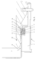
- the figure A shows a connector according to the earlier patent application, consisting of a plug 1, which is preferably designed as a sheet metal bent part.
- the plug 1 forms a circumferential interior 2, which is filled by a hose, which is not shown here.
- the non-existing tube seals an interior with a pressure medium 3, which acts in the direction of arrow 12 on the connector.
- the counterpart to the plug 1 is formed by a nozzle 20 and in the space between the plug 1 and the nozzle 20, the novel lip seal 6 is arranged.
- a circumferential groove 5 is formed in the sheet material of the plug, in which said c-shaped lip seal 6 is inserted.
- the lip seal 6 consists of a static leg 8, which is sealingly supported with a lower and arranged at the front end sealing boss 22 on the groove base.
- the static leg 8 passes through a base leg 17 in a dynamic leg 7, which also applies sealingly with its front free part on the inner circumference of the nozzle 20.
- the pressure medium 3 thus acts in the direction of arrow 12 on the annular gap 4 and tends to "inflate” the lip seal.
- the pump chamber 15 is sealed in an undesirable manner with respect to the atmosphere, because the base leg 17 still bears sealingly against the groove flank 11 of the groove 5 and thus does not provide relief for the pump chamber 15.
- the stored in the pump chamber 15 pressure medium is then removed from this pump chamber 15 via the groove flank 11 in the direction of the outer space 10, resulting in an undesirable leakage.
- the pumping effect is described, which ensures that in small portions (droplets), the pressure medium is discharged via the unwanted pumping effect in the outer space 10.
- the same conditions apply even if the pressure medium is not a liquid medium but a gaseous medium.
- An essential feature of the invention is that according to Figure 1, the lip seal 6 at least in the region of the base leg evenly distributed around the circumference, pointing in the radial direction, vent grooves 18 which interrupts the sealing compound of the base leg 17 in the groove flank 11 of the plug groove 5.
- the pump chamber 15 is therefore always open in the direction of the exterior space 10.
- nubs 23 can be provided which protrude beyond the inside width of the base leg 17 and thus represent a kinematic reversal of the aforementioned vent grooves 18.
- venting measures can not or not only be provided in the area of the lip seal 6, but they can also be provided in the region of the groove flank 11.
- the figure 2 shows in dashed lines a first embodiment, which shows that in the region of the groove flank 11 openings 24 can be provided in the axial direction, which also extend through the adjacent edge of the plug, so also an air-tight connection with the Outdoor space 10 to allow.
- FIG 3 shows another embodiment of the structural transformation of the groove flank 11, which also in combination with the ventilation of the lip seal or solves the inventive technical teaching.
- 11 notches 25 are arranged at uniform intervals distributed around the circumference in the region of the groove flank, which consequently also result in an air-tight connection between the pump chamber 15 and the outer space 10.
- venting measures are variable within wide limits, in order to achieve that no sealing effect between the base leg 17 and the groove flank 11 is formed, so as to connect the pump chamber 15 airtight with the outer space 10.
- the sealing ring is made of an elastomeric material, such as. As a rubber, rubber, a polymer plastic and the like.
- the sealing ring With a nominal diameter of the plug-in connection of 55 mm, the sealing ring has only an axial length of about 4.5 mm, a height of 4 to 4.5 mm in the uninstalled state.
- the thickness of the static leg is a maximum of 2 mm, while the thickness of the dynamic leg is about 1 to 2 mm.
- An additional embodiment of the invention provides that the plug 1 in the region of the forming pump chamber 15 has a ventilation hole 28, which performs a continuous ventilation / venting of the resulting pump chamber 15.
Landscapes
- Engineering & Computer Science (AREA)
- General Engineering & Computer Science (AREA)
- Mechanical Engineering (AREA)
- Physics & Mathematics (AREA)
- Fluid Mechanics (AREA)
- Gasket Seals (AREA)
- Pressure Vessels And Lids Thereof (AREA)
- Compressor (AREA)
Applications Claiming Priority (1)
| Application Number | Priority Date | Filing Date | Title |
|---|---|---|---|
| DE102005009688A DE102005009688B3 (de) | 2005-03-03 | 2005-03-03 | Steckverbindung mit Formdichtring und Entlüftung |
Publications (1)
| Publication Number | Publication Date |
|---|---|
| EP1698819A1 true EP1698819A1 (de) | 2006-09-06 |
Family
ID=35852822
Family Applications (1)
| Application Number | Title | Priority Date | Filing Date |
|---|---|---|---|
| EP06003331A Withdrawn EP1698819A1 (de) | 2005-03-03 | 2006-02-18 | Steckverbindung mit Formdichtung und Entlüftung |
Country Status (5)
| Country | Link |
|---|---|
| US (1) | US7686345B2 (https=) |
| EP (1) | EP1698819A1 (https=) |
| JP (1) | JP2006242385A (https=) |
| CN (1) | CN1904455A (https=) |
| DE (1) | DE102005009688B3 (https=) |
Cited By (1)
| Publication number | Priority date | Publication date | Assignee | Title |
|---|---|---|---|---|
| EP2083205A3 (de) * | 2008-01-28 | 2011-01-12 | Henn GmbH & Co.KG | Steckverbindung zum Verbinden von Leitungen für flüssige oder gasformige Medien |
Families Citing this family (7)
| Publication number | Priority date | Publication date | Assignee | Title |
|---|---|---|---|---|
| DE102010013412B4 (de) * | 2010-03-30 | 2014-05-22 | Norma Germany Gmbh | Abgasleitung für ein Kraftfahrzeug und Abgasanlage |
| US20120119446A1 (en) * | 2010-11-17 | 2012-05-17 | Schaeffler Technologies Gmbh & Co. Kg | Sealing unit for controlled lubrication flow |
| KR101371937B1 (ko) * | 2012-08-13 | 2014-03-10 | 주식회사 만도 | 랙-피니언 타입 조향장치 |
| AT14083U1 (de) * | 2014-03-03 | 2015-04-15 | Henn Gmbh & Co Kg | Dichtung |
| PL3149381T3 (pl) | 2014-05-30 | 2019-04-30 | Oetiker Ny Inc | Złącze dla płynu z nasadką zabezpieczającą całkowite wstawienie z pomocniczymi zatrzaskami |
| US11092269B2 (en) | 2014-05-30 | 2021-08-17 | Oetiker Ny, Inc. | Fluid connector with full insertion assurance cap with secondary latches |
| JP6286290B2 (ja) * | 2014-06-18 | 2018-02-28 | 矢崎総業株式会社 | パッキンの取付構造 |
Citations (6)
| Publication number | Priority date | Publication date | Assignee | Title |
|---|---|---|---|---|
| US2230725A (en) * | 1937-05-28 | 1941-02-04 | Goodrich Co B F | Sealing structure |
| GB1223575A (en) * | 1967-10-06 | 1971-02-24 | Wavin N V Zwolle | A pipe connection for suction pipe lines |
| DE2413750A1 (de) | 1973-04-24 | 1974-11-21 | Legris France Sa | Anschluss fuer druckmittelleitungen |
| US5205568A (en) * | 1991-03-14 | 1993-04-27 | Festo Kg | Sealing ring |
| US6007106A (en) * | 1993-10-29 | 1999-12-28 | Snap-Tite Technologies, Inc. | Hydraulic coupling |
| DE102004019800A1 (de) | 2004-04-23 | 2005-11-24 | Henn Gmbh & Co. Kg | Steckverbindung mit einem Formdichtring |
Family Cites Families (35)
| Publication number | Priority date | Publication date | Assignee | Title |
|---|---|---|---|---|
| US2049801A (en) * | 1935-08-06 | 1936-08-04 | Ellsworth D Gage | Coupling for overhead irrigation pipes |
| US2743899A (en) * | 1951-10-15 | 1956-05-01 | Wilbur C Kinney | Irrigation pipe joint with valved gasket |
| US2975799A (en) * | 1956-07-09 | 1961-03-21 | Fmc Corp | Combination pipe coupling and automatic drain valve |
| US2962314A (en) * | 1958-07-09 | 1960-11-29 | Mcdowell Mfg Co | Gasket |
| US3279806A (en) * | 1964-02-21 | 1966-10-18 | Goodrich Co B F | Seal assembly |
| US3315970A (en) * | 1965-02-08 | 1967-04-25 | John W Holoway | Flexible gasket for high and low pressure pipe joints |
| US3409314A (en) * | 1966-05-27 | 1968-11-05 | Homer D. Roe | Pipe couplings |
| JPS498658U (https=) * | 1972-04-28 | 1974-01-24 | ||
| US4036512A (en) * | 1974-10-01 | 1977-07-19 | Robert Arthur Francis | Pipe joints |
| JPS5540215U (https=) * | 1978-09-06 | 1980-03-14 | ||
| US4239242A (en) * | 1978-12-18 | 1980-12-16 | Burns William G | Pipe union and seal |
| JPS607386U (ja) * | 1983-06-22 | 1985-01-19 | 株式会社 潤工社 | 管継手用シ−ルリング |
| NL8502217A (nl) * | 1985-08-09 | 1987-03-02 | Single Buoy Moorings | Afdichting voor een draaibare leidingkoppeling. |
| JPH0526326Y2 (https=) * | 1985-12-16 | 1993-07-02 | ||
| JPH063219Y2 (ja) * | 1986-12-27 | 1994-01-26 | カヤバ工業株式会社 | シ−ル部材 |
| US4893847A (en) * | 1988-07-05 | 1990-01-16 | Stainless Steel Products, Inc. | Bearing seal for universal ball joint |
| JPH0338404U (https=) * | 1989-08-25 | 1991-04-15 | ||
| DK0511891T3 (da) * | 1991-04-29 | 1995-07-24 | Caillau Ets | Forbindelseselement til lynkobling af et rør |
| US5411298A (en) * | 1993-05-18 | 1995-05-02 | Imodco, Inc. | High pressure seal arrangement |
| US5975589A (en) * | 1993-10-29 | 1999-11-02 | Snap-Tite Technologies, Inc. | Hydraulic coupling |
| US5556139A (en) * | 1993-10-29 | 1996-09-17 | Snap-Tite, Inc. | Hydraulic coupling |
| JP2753461B2 (ja) * | 1995-05-31 | 1998-05-20 | シーケーディ株式会社 | リップパッキン及びシール構造 |
| DE19522691A1 (de) * | 1995-06-22 | 1997-01-02 | Henn Gmbh & Co Kg | Steckverbindung für den Anschluß von Rohr- und Schlauchleitungen |
| DE19522690A1 (de) * | 1995-06-22 | 1997-01-02 | Henn Gmbh & Co Kg | Steckverbindung für den Anschluß von Rohr- und Schlauchleitungen |
| US5749606A (en) * | 1996-02-13 | 1998-05-12 | General Motors Corporation | Connector assembly with retainer |
| CN1126888C (zh) * | 1999-02-18 | 2003-11-05 | 萱场工业株式会社 | 密封构造 |
| JP2001336641A (ja) * | 2000-05-25 | 2001-12-07 | Nok Corp | 密封構造 |
| JP2001343074A (ja) * | 2000-06-01 | 2001-12-14 | Nok Corp | 密封装置 |
| JP4535606B2 (ja) * | 2000-12-06 | 2010-09-01 | Nok株式会社 | ピストンカップ |
| DE10136250C2 (de) * | 2001-03-30 | 2003-02-27 | Hydrotechnik Gmbh | Ventilkupplung für fluidische Systeme |
| US7229102B2 (en) * | 2002-12-20 | 2007-06-12 | Deublin Company | Fluid coolant union |
| DE10347927B4 (de) * | 2003-10-15 | 2007-06-28 | Henn Gmbh & Co. Kg | Verfahren und Vorrichtung zur Herstellung einer Rohrpressverbindung an einer Steckverbindung |
| DE10347926A1 (de) * | 2003-10-15 | 2005-05-19 | Henn Gmbh & Co. Kg | Steckverbindung für den Anschluss von Rohren und Schläuchen mit Sicherungsring |
| DE102004019799A1 (de) * | 2004-04-23 | 2005-11-17 | Henn Gmbh & Co. Kg | Verfahren zur Herstellung einer Steckverbindung und Steckverbindung |
| DE102005050490A1 (de) * | 2005-10-21 | 2007-04-26 | Henn Gmbh & Co. Kg | Steckverbindung an Rohren und Schläuchen mit einem Rohrrastring |
-
2005
- 2005-03-03 DE DE102005009688A patent/DE102005009688B3/de not_active Expired - Fee Related
-
2006
- 2006-02-18 EP EP06003331A patent/EP1698819A1/de not_active Withdrawn
- 2006-03-03 US US11/366,836 patent/US7686345B2/en not_active Expired - Fee Related
- 2006-03-03 CN CNA2006100928701A patent/CN1904455A/zh active Pending
- 2006-03-03 JP JP2006058690A patent/JP2006242385A/ja active Pending
Patent Citations (7)
| Publication number | Priority date | Publication date | Assignee | Title |
|---|---|---|---|---|
| US2230725A (en) * | 1937-05-28 | 1941-02-04 | Goodrich Co B F | Sealing structure |
| GB1223575A (en) * | 1967-10-06 | 1971-02-24 | Wavin N V Zwolle | A pipe connection for suction pipe lines |
| DE2413750A1 (de) | 1973-04-24 | 1974-11-21 | Legris France Sa | Anschluss fuer druckmittelleitungen |
| DE2413750C2 (de) | 1973-04-24 | 1987-02-12 | Legris France S.A., Ozoir-la-Ferriere | Anschluß für Druckmittelleitungen |
| US5205568A (en) * | 1991-03-14 | 1993-04-27 | Festo Kg | Sealing ring |
| US6007106A (en) * | 1993-10-29 | 1999-12-28 | Snap-Tite Technologies, Inc. | Hydraulic coupling |
| DE102004019800A1 (de) | 2004-04-23 | 2005-11-24 | Henn Gmbh & Co. Kg | Steckverbindung mit einem Formdichtring |
Cited By (1)
| Publication number | Priority date | Publication date | Assignee | Title |
|---|---|---|---|---|
| EP2083205A3 (de) * | 2008-01-28 | 2011-01-12 | Henn GmbH & Co.KG | Steckverbindung zum Verbinden von Leitungen für flüssige oder gasformige Medien |
Also Published As
| Publication number | Publication date |
|---|---|
| DE102005009688B3 (de) | 2006-03-09 |
| CN1904455A (zh) | 2007-01-31 |
| JP2006242385A (ja) | 2006-09-14 |
| US7686345B2 (en) | 2010-03-30 |
| US20060202472A1 (en) | 2006-09-14 |
Similar Documents
| Publication | Publication Date | Title |
|---|---|---|
| DE3424675C2 (de) | Schlauchkupplung | |
| DE19826323A1 (de) | Dichtungsanordnung | |
| DE60009205T2 (de) | Tülle | |
| EP2005042B1 (de) | Aufblasbare dichtvorrichtung für ein formwerkzeug | |
| DE2906317A1 (de) | Rohrverbindungsteil und mit diesem hergestellte rohrverbindung | |
| EP3114378A1 (de) | Dichtung | |
| DE102017001269A1 (de) | Filterelement und Filteranordnung | |
| EP1698819A1 (de) | Steckverbindung mit Formdichtung und Entlüftung | |
| EP2927541A1 (de) | Dichtungselement sowie Konstruktion eines Leitungsgelenkes | |
| EP1426669A2 (de) | Wellrohr-Verbindungsanordnung sowie Wellrohr | |
| EP0596230B1 (de) | Steckverbindung von Rohrstücken | |
| EP3188919B2 (de) | Türdichtungsvorrichtung, türdichtungssystem und türflügel für ein schienenfahrzeug | |
| DE102018122507A1 (de) | Anschlussvorrichtung für Rohrleitungen mit Leckageanzeige | |
| DE3345903A1 (de) | Schlauchkupplung | |
| DE102015105651B4 (de) | Dichtungselement für einen Lüftungskanal, Lüftungssystem mit Dichtung und Verfahren zur Herstellung eines Lüftungssystems | |
| DE29820394U1 (de) | Tülle mit Verbindungsabschnitt | |
| EP1945985B1 (de) | Verbindungssystem für leitungen, armaturen oder aggregate | |
| DE69109155T2 (de) | Herstellungsverfahren eines Dichtungsringes und nach einem solchen Verfahren gewonnenes Produkt. | |
| DE102014225279A1 (de) | Anschlussvorrichtung für eine Fluidleitung | |
| WO2023174735A9 (de) | Türdichtung für eine aufzugskabine | |
| EP2403999B1 (de) | Strahlregler | |
| DE102010048226A1 (de) | Verbindungsvorrichtung für zwei sich abschnittsweise überlappende Leitungen | |
| DE60110447T2 (de) | Dichtungsring | |
| DE102017116926A1 (de) | Dichtringträger, Kolben und Nehmerzylinder | |
| DE3408369A1 (de) | Verfahren zum herstellen einer rotationsbuerste |
Legal Events
| Date | Code | Title | Description |
|---|---|---|---|
| PUAI | Public reference made under article 153(3) epc to a published international application that has entered the european phase |
Free format text: ORIGINAL CODE: 0009012 |
|
| AK | Designated contracting states |
Kind code of ref document: A1 Designated state(s): AT BE BG CH CY CZ DE DK EE ES FI FR GB GR HU IE IS IT LI LT LU LV MC NL PL PT RO SE SI SK TR |
|
| AX | Request for extension of the european patent |
Extension state: AL BA HR MK YU |
|
| 17P | Request for examination filed |
Effective date: 20061025 |
|
| AKX | Designation fees paid |
Designated state(s): DE ES FR GB IT |
|
| 17Q | First examination report despatched |
Effective date: 20090804 |
|
| STAA | Information on the status of an ep patent application or granted ep patent |
Free format text: STATUS: THE APPLICATION IS DEEMED TO BE WITHDRAWN |
|
| 18D | Application deemed to be withdrawn |
Effective date: 20091215 |