EP1698286A2 - Zielgerät für einen Verriegelungsnagel - Google Patents
Zielgerät für einen Verriegelungsnagel Download PDFInfo
- Publication number
- EP1698286A2 EP1698286A2 EP06004135A EP06004135A EP1698286A2 EP 1698286 A2 EP1698286 A2 EP 1698286A2 EP 06004135 A EP06004135 A EP 06004135A EP 06004135 A EP06004135 A EP 06004135A EP 1698286 A2 EP1698286 A2 EP 1698286A2
- Authority
- EP
- European Patent Office
- Prior art keywords
- nail
- sleeve
- parts
- receiving portion
- bore
- Prior art date
- Legal status (The legal status is an assumption and is not a legal conclusion. Google has not performed a legal analysis and makes no representation as to the accuracy of the status listed.)
- Granted
Links
Images
Classifications
-
- A—HUMAN NECESSITIES
- A61—MEDICAL OR VETERINARY SCIENCE; HYGIENE
- A61B—DIAGNOSIS; SURGERY; IDENTIFICATION
- A61B17/00—Surgical instruments, devices or methods, e.g. tourniquets
- A61B17/16—Bone cutting, breaking or removal means other than saws, e.g. Osteoclasts; Drills or chisels for bones; Trepans
- A61B17/17—Guides or aligning means for drills, mills, pins or wires
- A61B17/1725—Guides or aligning means for drills, mills, pins or wires for applying transverse screws or pins through intramedullary nails or pins
-
- A—HUMAN NECESSITIES
- A61—MEDICAL OR VETERINARY SCIENCE; HYGIENE
- A61B—DIAGNOSIS; SURGERY; IDENTIFICATION
- A61B17/00—Surgical instruments, devices or methods, e.g. tourniquets
- A61B2017/00477—Coupling
Definitions
- the invention relates to a target device for a locking nail having a first portion which is releasably connectable to the associated end of the nail, a bow-like second portion connected to the first portion having a receiving portion which extends approximately parallel to the nail when the Nail with the first Section is connected and having at least one transverse bore for the approximately fitting receiving a guide sleeve.
- a particular problem with locking nails is the finding of the transverse bores in the implanted nail.
- Target devices are therefore used for this purpose.
- One category of targeting devices works with X-rays.
- the transverse bores of the locking nail in the bone are displayed on a monitor.
- an image of a destination element takes place. In this way it is possible to mark on the outside the point which lies on the axis of the transverse bores.
- target devices are firmly connected to one end of a nail.
- a bow-shaped portion has at least one through-hole whose axis is aligned with the axis of a transverse bore of the nail when it is attached to the target device.
- To guide the drilling tool or the bone screw is also known to insert a guide sleeve through the transverse bore of the target device, which is advanced up against the outside of the bone.
- the guide sleeve fits into the transverse bore of the target device, it must be able to be moved relatively easily by hand, so as not to complicate the surgeon's work. However, there is a risk that the guide sleeve slips backwards when handling the target device or when drilling and also when screwing in bone screws.
- the invention is therefore an object of the invention to provide a target device for a locking nail, in which the sleeve can be easily adjusted and fixed in the respective position.
- the receiving portion has two parts, wherein the one which faces a nail received, is rigidly connected to the other portions of the target device, while the second part is movable relative to the first part against spring force.
- the transverse bore extends through both parts, wherein the partial bores are arranged so that when relaxed second part, the sleeve is kept slightly clamped. If, however, the second part is pressed in the direction of the first part, the sleeve can be moved more or less freely in the partial bores.
- a sleeve is received by the transverse bore of the target device and pressed in the direction of the received nail, this leads to a certain deformation of the second part in the direction of the first part, whereby the sleeve can be moved against a certain resistance, without an additional operation is necessary . If too much force is to be applied, it is sufficient to press lightly on the second part, so that the sleeve can be moved. In this case, the sleeve can also be pushed backwards, if it is to be removed. It is essential, however, that the sleeve can not be pulled out of the bore even with relatively great force, if the second part is not printed in the direction of the first part.
- the pivotable second part is in the attempt to pull out the sleeve pivoted away from the first part and increases the clamping action. This increases with applied force, whereby the sleeve is held securely against being pushed back.
- first and second part are integrally molded of elastic material.
- Another embodiment provides that the second part is attached to the free end of the first part and separated from it by an approximately parallel slot.
- the entire target device can be molded in one piece, for example cast. However, it is more advantageous to form the receiving portion in one piece and the rest of the device in one piece, since it is then easier to choose a suitable, sufficiently resilient material for the receiving portion. For the other sections, however, a relatively solid and possibly rigid material is required, especially if the target device also serves as impactor.
- a target nail for a locking nail having a first portion releasably connectable to the associated end of the nail is a bow-shaped second portion connected to the first portion having a receiving portion which is approximately parallel to the nail when the nail is connected to the first portion and the at least one transverse bore has provided for the approximately fitting receiving a guide sleeve, wherein the receiving portion of a rigidly molded with the second portion, the first portion facing first part and a second movable relative to the first part against spring force outer second part, wherein the transverse bore extends through both parts and the bore in the parts is selected so that when relaxed second part, the sleeve is held slightly clamped and with a certain adjustment of the second part to the first part in the bore is freely displaceable.
- the first and second parts are integrally molded from an elastic material.
- the second part is attached to the free end of the first part and separated therefrom by a parallel slot.
- the receiving portion is integrally molded.
- the first and second sections are integrally molded.
- the first part of the receiving portion is connected to the second portion via connecting elements.
- first and second parts are made of suitable plastic material and first and second sections are formed of metal.
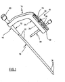
- Fig. 1 shows in perspective a first embodiment of a target device according to the invention.
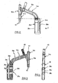
- Fig. 2 shows the side view of a second embodiment of a target device according to the invention.
- FIG. 3 shows a section through the target device according to FIG. 2.
- FIG. 4 shows a side view of the aiming device according to FIG. 2 in the direction of the arrow 4.
- a target device 10 which is composed of a first portion 12 and a bow-shaped second portion 14.
- the bow-shaped portion 14 has at the left end a through hole for receiving a fastening sleeve 16 which is rigidly secured in this bore.
- the sleeve has at the lower end a connecting portion (not shown) for connection to a known locking nail 18.
- Orientation means of the receiving portion ensure that the nail 18 is connected in a predetermined rotational position with the sleeve 16.
- the locking nail 18 has in the upper region at 22 transverse holes and in the lower region transverse bores 24. They serve to receive bone screws (not shown), which are screwed through the bone and through the transverse bores 22, 24, as known per se.
- the device section 14 has a receiving portion 26, which consists of a first part 28 and a second part 30.
- the first part is integrally formed with the second portion 14 and rigidly connected thereto.
- the second part 30 is connected at the free end at 32 to the section 28 and separated from it by an approximately parallel incision 34. Since the material of which the portion 14 is formed is resilient, the member 30 can be pivoted toward and away from the member 28.
- Transverse bores 36 extend through the parts 28, 30 and serve to receive a guide sleeve 38, which is inserted through the bottom hole.
- the guide sleeve 38 can each be approximately suitably received by the bores 36 in the parts 28, 30, wherein, however, the position of the holes in the two parts 28, 30 to each other is such that the sleeve is held in a relaxed position of the part 30 slightly clamped , Will that be Part 30 deformed a little towards Part 28, the sleeve 38 can be easily moved into the holes 36. If, however, the part 30 is deformed in the opposite direction, the sleeve 38 is clamped and can not be moved.
- the bores 36 are aligned in their axis to the transverse bores 22. If a drilling tool is guided through the sleeve 38, it drills the bone at a location lying on the common axis of a transverse bore of the nail. For this procedure, the sleeve 38 is advanced against the bone. A pushing back of the sleeve 38 is prevented by the described clamping action. If the sleeve is nevertheless to be removed, the part 30 is moved a little against the part 28.
- FIG. 2 to 4 a target device 10a is shown, which is constructed similar to that of FIG. 1. Therefore, the same parts are given the same reference numerals, but an a is added.
- the receiving portion 26a is connected to the second portion 14a via connecting sleeves 38a.
- the portion 14a is formed integrally with the portion 12a of a suitable metallic material while, for example, the receiving portion 26a is made of plastic material. Otherwise, the receiving portion 26a is completely identical to that of Fig. 1 is formed.
- the second portion 14a has an upwardly projecting punch 40, which is suitably fixed. It can be seen in Fig. 3 that the first portion 12a has a through hole 42 for receiving a fastening or bolt for attaching a locking nail. Two projections 44 at the lower end of the sleeve portion 16a cooperate with not shown recesses of a locking nail to give this the correct orientation.
- the releasable attachment of the receiving portion 26a has the advantage that different receiving portions can be attached depending on the inserted locking nail. If, for example, with regard to the bores 24 of the locking nail according to FIG. 1, a hole has to be drilled in the bone, another target device is required. In the embodiment according to FIGS. 2 to 4, therefore, a suitable receiving section 26a can be attached to the remaining part of the target device.
Abstract
Description
- Die Erfindung bezieht sich auf ein Zielgerät für einen Verriegelungsnagel mit einem ersten Abschnitt, der mit dem zugeordneten Ende des Nagels lösbar verbindbar ist, einem mit dem ersten Abschnitt verbundenen bügelartigen zweiten Abschnitt, der einen Aufnahmeabschnitt aufweist, der annähernd parallel zum Nagel verläuft, wenn der Nagel mit dem ersten Abschnitt verbunden ist und der mindestens eine Querbohrung aufweist für die annähernd passende Aufnahme einer Führungshülse.
- In den Unterschenkel- oder Oberschenkelknochen einführbare Verriegelungsnägel weisen zumeist mehrere Querbohrungen auf, durch die hindurch Knochenschrauben geführt werden, um die Verriegelungsnägel sicher im Knochenkanal zu halten. Insbesondere wird dadurch eine Drehsicherung erhalten.
- Ein besonderes Problem bei Vernegelungsnägeln ist das Auffinden der Querbohrungen beim implantierten Nagel. Hierfür werden daher Zielgeräte verwendet. Eine Kategorie von Zielgeräten arbeitet mit Röntgenstrahlen. Die Querbohrungen des Verriegelungsnagels im Knochen werden auf einem Monitor abgebildet. Ferner findet eine Abbildung eines Zielelements statt. Auf diese Weise ist es möglich, an der Außenseite die Stelle zu markieren, die auf der Achse der Querbohrungen liegt.
- Bei einer anderen Kategorie werden Zielgeräte fest mit einem Ende eines Nagels verbunden. Ein bügelartiger Abschnitt weist mindestens eine Durchbohrung auf, deren Achse mit der Achse einer Querbohrung des Nagels ausgerichtet ist, wenn er am Zielgerät angebracht ist. Zur Führung des Bohrwerkzeugs bzw. der Knochenschraube ist auch bekannt, durch die Querbohrung des Zielgerätes eine Führungshülse zu stecken, die bis gegen die Außenseite des Knochens vorgeschoben wird.
- Die Führungshülse sitzt zwar passend in der Querbohrung des Zielgerätes, muss jedoch von Hand relativ leicht bewegt werden können, um dem Chirurgen die Arbeit nicht zu erschweren. Dadurch besteht jedoch Gefahr, dass bei der Handhabung des Zielgerätes bzw. beim Bohren und auch beim Einschrauben von Knochenschrauben die Führungshülse nach hinten verrutscht.
- Der Erfindung liegt daher die Aufgabe zugrunde, ein Zielgerät für einen Verriegelungsnagel zu schaffen, bei dem die Hülse auf einfache Weise verstellt und in der jeweiligen Position fixiert werden kann.
- Diese Aufgabe wird durch die Merkmale des Anspruchs 1 gelöst.
- Bei dem erfindungsgemäßen Zielgerät weist der Aufnahmeabschnitt zwei Teile auf, wobei der eine, der einem aufgenommenen Nagel zugekehrt ist, starr mit den übrigen Abschnitten des Zielgeräts verbunden ist, während der zweite Teil gegen Federkraft relativ zum ersten Teil bewegbar ist. Die Querbohrung erstreckt sich durch beide Teile, wobei die Teilbohrungen so angeordnet sind, dass bei entspanntem zweiten Teil die Hülse leicht geklemmt gehalten ist. Wird hingegen der zweite Teil in Richtung des ersten Teils gedrückt, lässt sich die Hülse mehr oder weniger frei in den Teilbohrungen verschieben.
- Wird eine Hülse von der Querbohrung des Zielgeräts aufgenommen und in Richtung des aufgenommenen Nagels gedrückt, führt dies zu einer gewissen Verformung des zweiten Teils in Richtung des ersten Teils, wodurch die Hülse gegen einen gewissen Widerstand verschoben werden kann, ohne dass eine zusätzliche Betätigung notwendig ist. Falls hierzu eine zu große Kraft aufzubringen ist, genügt ein leichtes Drücken auf den zweiten Teil, damit die Hülse verschoben werden kann. Hierbei kann die Hülse auch nach hinten geschoben werden, falls sie entfernt werden soll. Wesentlich ist jedoch, dass die Hülse auch mit relativ großem Kraftaufwand nicht aus der Bohrung herausgezogen werden kann, wenn das zweite Teil nicht in Richtung erstes Teil gedruckt wird. Das verschwenkbare zweite Teil wird bei dem Versuch, die Hülse herauszuziehen, vom ersten Teil fort geschwenkt und erhöht die Klemmwirkung. Diese steigt mit aufgebrachter Kraft, wodurch die Hülse gegen ein Zurückschieben sicher gehalten ist.
- Es gibt verschiedene Möglichkeiten, die erfindungsgemäße Konstruktion zu verwirklichen. Eine Ausgestaltung sieht hierzu vor, dass erstes und zweites Teil einteilig aus elastischem Werkstoff geformt sind. Es ist natürlich auch denkbar, das zweite Teil am ersten anzulenken und zwischen beiden eine Feder wirken zu lassen.
- Eine andere Ausgestaltung sieht vor, dass das zweite Teil am freien Ende des ersten Teils angebracht und von diesem durch einen annähernd parallelen Schlitz getrennt ist.
- Das gesamte Zielgerät kann einteilig geformt werden, beispielsweise gegossen werden. Es ist jedoch vorteilhafter, den Aufnahmeabschnitt einteilig und das übrige Gerät einteilig zu formen, da es dann leichter ist, für den Aufnahmeabschnitt einen geeigneten, ausreichend federnden Werkstoff zu wählen. Für die übrigen Abschnitte ist hingegen ein relativ fester und ggf. starrer Werkstoff erforderlich, vor allem wenn das Zielgerät gleichzeitig als Einschlaginstrument dient.
- In einem exemplarischen Ausführungsbeispiel wird Zielgerät für einen Verriegelungsnagel mit einem ersten Abschnitt, der mit dem zugeordneten Ende des Nagels lösbar verbindbar ist, einem mit dem ersten Abschnitt verbundenen bügelartigen zweiten Abschnitt, der einen Aufnahmeabschnitt aufweist, der annähernd parallel zum Nagel verläuft, wenn der Nagel mit dem ersten Abschnitt verbunden ist und der mindestens eine Querbohrung aufweist für die annähernd passende Aufnahme einer Führungshülse geschaffen, wobei der Aufnahmeabschnitt aus einem starr mit dem zweiten Abschnitt geformten, dem ersten Abschnitt zugewandten ersten Teil und einen zweiten relativ zum ersten Teil gegen Federkraft bewegbaren äußeren zweiten Teil besteht, wobei sich die Querbohrung durch beide Teile hindurcherstreckt und die Bohrung in den Teilen so gewählt ist, dass bei entspanntem zweiten Teil die Hülse leicht klemmend gehalten ist und bei einer gewissen Verstellung des zweiten Teils auf das erste Teil zu in der Bohrung frei verschiebbar ist.
- In einem anderen exemplarischen Ausführungsbeispiel des Zielgeräts sind erstes und zweites Teil einteilig aus einem elastischen Werkstoff geformt.
- In einem anderen exemplarischen Ausführungsbeispiel des Zielgeräts ist das zweite Teil am freien Ende des ersten Teils angebracht und von diesem durch einen parallelen Schlitz getrennt.
- In einem anderen exemplarischen Ausführungsbeispiel des Zielgeräts ist der Aufnahmeabschnitt einteilig geformt.
- In einem anderen exemplarischen Ausführungsbeispiel des Zielgeräts sind erster und zweiter Abschnitt einteilig geformt.
- In einem anderen exemplarischen Ausführungsbeispiel des Zielgeräts ist der erste Teil des Aufnahmeabschnitts über Verbindungselemente mit dem zweiten Abschnitt verbunden.
- In einem anderen exemplarischen Ausführungsbeispiel des Zielgeräts sind erstes und zweites Teil aus geeignetem Kunststoffmaterial und erster Abschnitt und übriger zweiter Abschnitt aus Metall geformt.
- Die Erfindung wird nachfolgend anhand von Ausführungsbeispielen näher erläutert.
- Fig. 1 zeigt perspektivisch eine erste Ausführungsform eines Zielgeräts nach der Erfindung.
- Fig. 2 zeigt die Seitenansicht einer zweiten Ausführungsform eines Zielgeräts nach der Erfindung.
- Fig. 3 zeigt einen Schnitt durch das Zielgerät nach Fig. 2.
- Fig. 4 zeigt eine Seitenansicht des Zielgeräts nach Fig. 2 in Richtung Pfeil 4.
- In Fig. 1 ist ein Zielgerät 10 dargestellt, das aus einem ersten Abschnitt 12 und einem bügelartigen zweiten Abschnitt 14 zusammengesetzt ist. Der bügelartige Abschnitt 14 weist am linken Ende eine Durchbohrung auf zur Aufnahme einer Befestigungshülse 16, welche starr in dieser Bohrung befestigt ist. Die Hülse hat am unteren Ende einen Anschlussabschnitt (nicht gezeigt) zur Verbindung mit einem an sich bekannten Verriegelungsnagel 18. Orientierungsmittel des Aufnahmeabschnitts sorgen dafür, dass der Nagel 18 in vorgegebener Drehlage mit der Hülse 16 verbunden wird. Hierzu dient zum Beispiel ein Schraubenbolzen, dessen Kopf bei 20 zu erkennen ist und dessen Gewinde mit einem Innengewindeabschnitt des Nagels 18 zusammenwirkt. Der Verriegelungsnagel 18 weist im oberen Bereich bei 22 Querbohrungen auf und im unteren Bereich Querbohrungen 24. Sie dienen zur Aufnahme von Knochenschrauben (nicht gezeigt), die quer durch den Knochen und durch die Querbohrungen 22, 24 hindurchgeschraubt werden, wie an sich bekannt.
- Der Geräteabschnitt 14 weist einen Aufnahmeabschnitt 26 auf, der aus einem ersten Teil 28 und einem zweiten Teil 30 besteht. Das erste Teil ist einteilig mit dem zweiten Abschnitt 14 geformt und starr mit diesem verbunden. Das zweite Teil 30 ist am freien Ende bei 32 an den Abschnitt 28 angebunden und von diesem durch einen annähernd parallel verlaufenden Einschnitt 34 getrennt. Da der Werkstoff, aus dem der Abschnitt 14 geformt ist, federnd ist, kann das Teil 30 auf das Teil 28 zu und von diesem fort verschwenkt bzw. gebogen werden.
- Querbohrungen 36 erstrecken sich durch die Teile 28, 30 und dienen zur Aufnahme einer Führungshülse 38, die durch die unterste Bohrung hindurchgesteckt ist. Die Führungshülse 38 kann jeweils annähernd passend von den Bohrungen 36 in den Teilen 28, 30 aufgenommen werden, wobei jedoch die Lage der Bohrungen in den beiden Teilen 28, 30 zueinander derart ist, dass die Hülse in entspannter Lage des Teils 30 leicht klemmend gehalten ist. Wird das Teil 30 ein wenig in Richtung Teil 28 verformt, lässt sich die Hülse 38 leicht in den Bohrungen 36 verschieben. Wird hingegen das Teil 30 in die entgegengesetzte Richtung verformt, wird die Hülse 38 eingeklemmt und kann nicht mehr bewegt werden.
- Die Bohrungen 36, insbesondere im Teil 28, sind in ihrer Achse zu den Querbohrungen 22 ausgerichtet. Wird durch die Hülse 38 ein Bohrwerkzeug geführt, bohrt es den Knochen an einer Stelle an, die auf der gemeinsamen Achse einer Querbohrung des Nagels liegt. Für diesen Vorgang wird die Hülse 38 gegen den Knochen vorgeschoben. Ein Zurückschieben der Hülse 38 wird durch die beschriebene Klemmwirkung verhindert. Soll die Hülse gleichwohl entfernt werden, wird das Teil 30 ein wenig gegen das Teil 28 bewegt.
- In den Figuren 2 bis 4 ist ein Zielgerät 10a dargestellt, das ähnlich aufgebaut ist wie das nach Fig. 1. Daher werden gleiche Teile mit gleichen Bezugszeichen versehen, denen jedoch ein a hinzugefügt ist.
- Man erkennt, dass bei dieser Ausführungsform der Aufnahmeabschnitt 26a über Verbindungshülsen 38a mit dem zweiten Abschnitt 14a verbunden ist. Der Abschnitt 14a ist einteilig mit dem Abschnitt 12a aus einem geeigneten metallischen Werkstoff geformt, während zum Beispiel der Aufnahmeabschnitt 26a aus Kunststoffmaterial besteht. Ansonsten ist der Aufnahmeabschnitt 26a völlig gleich zu dem nach Fig. 1 ausgebildet.
- Man erkennt, dass der zweite Abschnitt 14a einen nach oben stehenden Schlagdorn 40 aufweist, der in geeigneter Weise befestigt ist. Man erkennt in Fig. 3, dass der erste Abschnitt 12a eine durchgehende Bohrung 42 aufweist zur Aufnahme eines Befestigungs- bzw. Schraubbolzens zum Anbringen eines Verriegelungsnagels. Zwei Vorsprünge 44 am unteren Ende des Hülsenabschnitts 16a wirken mit nicht gezeigten Ausnehmungen eines Verriegelungsnagels zusammen, um diesem die richtige Orientierung zu geben.
- Die lösbare Befestigung des Aufnahmeabschnitts 26a hat den Vorteil, dass verschiedene Aufnahmeabschnitte angebracht werden können je nach eingesetztem Verriegelungsnagel. Muss zum Beispiel im Hinblick auf die Bohrungen 24 des Verriegelungsnagels nach Fig. 1 ein Loch in den Knochen gebohrt werden, bedarf es eines anderen Zielgerätes. Bei der Ausführungsform nach Fig. 2 bis 4 kann daher ein passender Aufnahmeabschnitt 26a an dem übrigen Teil des Zielgerätes angebracht werden.
Claims (7)
- Zielgerät für einen Verriegelungsnagel mit einem ersten Abschnitt, der mit dem zugeordneten Ende des Nagels lösbar verbindbar ist, einem mit dem ersten Abschnitt verbundenen bügelartigen zweiten Abschnitt, der einen Aufnahmeabschnitt aufweist, der annähernd parallel zum Nagel verläuft, wenn der Nagel mit dem ersten Abschnitt verbunden ist und der mindestens eine Querbohrung aufweist für die annähernd passende Aufnahme einer Führungshülse, wobei der Aufnahmeabschnitt (26, 26a) aus einem starr mit dem zweiten Abschnitt (14a) geformten, dem ersten Abschnitt (16a) zugewandten ersten Teil (28, 28a) und einen zweiten relativ zum ersten Teil (28a) gegen Federkraft bewegbaren äußeren zweiten Teil (30, 30a) besteht, wobei sich die Querbohrung (36, 36a) durch beide Teile (28, 30, 28a, 30a) hindurcherstreckt und die Bohrung (36, 36a) in den Teilen (28, 30, 28a, 30a) so gewählt ist, dass bei entspanntem zweiten Teil (30, 30a) die Hülse (38) leicht klemmend gehalten ist und bei einer gewissen Verstellung des zweiten Teils (30, 30a) auf das erste Teil (28, 28a) zu in der Bohrung (36, 36a) frei verschiebbar ist.
- Zielgerät nach Anspruch 1, wobei erstes und zweites Teil (28, 30, 28a, 30a) einteilig aus einem elastischen Werkstoff geformt sind.
- Zielgerät nach Anspruch 2, wobei das zweite Teil (30, 30a) am freien Ende des ersten Teils (28, 28a) angebracht und von diesem durch einen parallelen Schlitz (34, 34a) getrennt ist.
- Zielgerät nach einem der Ansprüche 1 bis 3, wobei der Aufnahmeabschnitt (26, 26a) einteilig geformt ist.
- Zielgerät nach einem der Ansprüche 1 bis 4, wobei erster und zweiter Abschnitt (14, 16) einteilig geformt sind.
- Zielgerät nach einem der Ansprüche 1 bis 4, wobei der erste Teil (28a) des Aufnahmeabschnitts (26a) über Verbindungselemente (38) mit dem zweiten Abschnitt (14a) verbunden ist.
- Zielgerät nach Anspruch 6, wobei erstes und zweites Teil (28a, 30a) aus geeignetem Kunststoffmaterial und erster Abschnitt (16a) und übriger zweiter Abschnitt (14a) aus Metall geformt sind.
Applications Claiming Priority (4)
| Application Number | Priority Date | Filing Date | Title |
|---|---|---|---|
| DE29806564U DE29806564U1 (de) | 1998-04-09 | 1998-04-09 | Zielgerät für einen Verriegelungsnagel |
| EP99106096A EP0948936B1 (de) | 1998-04-09 | 1999-03-26 | Zielgerät für einen Verriegelungsnagel |
| CA002272163A CA2272163C (en) | 1998-04-09 | 1999-05-18 | Targeting apparatus for a locking nail |
| AU29087/99A AU716601B3 (en) | 1998-04-09 | 1999-05-18 | Targeting apparatus for a locking nail |
Related Parent Applications (1)
| Application Number | Title | Priority Date | Filing Date |
|---|---|---|---|
| EP99106096A Division EP0948936B1 (de) | 1998-04-09 | 1999-03-26 | Zielgerät für einen Verriegelungsnagel |
Publications (3)
| Publication Number | Publication Date |
|---|---|
| EP1698286A2 true EP1698286A2 (de) | 2006-09-06 |
| EP1698286A3 EP1698286A3 (de) | 2008-05-28 |
| EP1698286B1 EP1698286B1 (de) | 2009-11-18 |
Family
ID=32096389
Family Applications (2)
| Application Number | Title | Priority Date | Filing Date |
|---|---|---|---|
| EP06004135A Expired - Lifetime EP1698286B1 (de) | 1998-04-09 | 1999-03-26 | Zielgerät für einen Verriegelungsnagel |
| EP99106096A Expired - Lifetime EP0948936B1 (de) | 1998-04-09 | 1999-03-26 | Zielgerät für einen Verriegelungsnagel |
Family Applications After (1)
| Application Number | Title | Priority Date | Filing Date |
|---|---|---|---|
| EP99106096A Expired - Lifetime EP0948936B1 (de) | 1998-04-09 | 1999-03-26 | Zielgerät für einen Verriegelungsnagel |
Country Status (7)
| Country | Link |
|---|---|
| US (1) | US6039739A (de) |
| EP (2) | EP1698286B1 (de) |
| JP (1) | JP4130719B2 (de) |
| AU (1) | AU716601B3 (de) |
| CA (1) | CA2272163C (de) |
| DE (3) | DE29806564U1 (de) |
| ES (2) | ES2264229T3 (de) |
Families Citing this family (45)
| Publication number | Priority date | Publication date | Assignee | Title |
|---|---|---|---|---|
| DE29804268U1 (de) * | 1998-03-11 | 1998-05-14 | Synthes Ag | Spiralklingen-Insertions-Instrument |
| DE20003053U1 (de) * | 2000-02-19 | 2001-06-28 | Howmedica Gmbh | Verriegelungsnagel und Zielgerät |
| US6878166B2 (en) * | 2000-08-28 | 2005-04-12 | Ron Clark | Method and implant for securing ligament replacement into the knee |
| US7530999B2 (en) * | 2000-08-28 | 2009-05-12 | Biomet Sports Medicine, Llc | Method and implant for securing ligament replacement into the knee |
| US7179244B2 (en) * | 2001-03-15 | 2007-02-20 | Specialized Health Products, Inc. | Resettable safety shield for medical needles |
| US7713300B2 (en) * | 2002-01-31 | 2010-05-11 | Biomet Sports Medicince, LLC | Apparatus and method for manipulating a flexible strand and soft tissue replacement during surgery |
| US20060206206A1 (en) | 2003-06-06 | 2006-09-14 | Peyman Gholam A | Intraocular telescope |
| US7033364B1 (en) | 2002-01-31 | 2006-04-25 | Arthrotek, Inc. | Apparatus and method for manipulating a flexible strand and soft tissue replacement during surgery |
| DE20204126U1 (de) * | 2002-03-15 | 2003-07-24 | Stryker Trauma Gmbh | Zielgerät für Verriegelungsnägel |
| DE20204655U1 (de) | 2002-03-21 | 2002-06-13 | Stryker Trauma Gmbh | Verriegelungsnagel und Zielgerät |
| US7056322B2 (en) * | 2002-03-28 | 2006-06-06 | Depuy Orthopaedics, Inc. | Bone fastener targeting and compression/distraction device for an intramedullary nail and method of use |
| DE10227379B4 (de) * | 2002-06-20 | 2005-12-08 | Stryker Trauma Gmbh | Implantationssystem und Zielgerät dafür |
| DE20211806U1 (de) | 2002-08-01 | 2002-10-17 | Stryker Trauma Gmbh | Zielgerät für einen Verriegelungsnagel |
| US20100249782A1 (en) * | 2002-10-03 | 2010-09-30 | Durham Alfred A | Intramedullary nail targeting device |
| CA2500845C (en) | 2002-10-03 | 2012-07-31 | Virginia Tech Intellectual Properties, Inc. | Magnetic targeting device |
| DE20216857U1 (de) * | 2002-11-02 | 2003-02-20 | Stryker Trauma Gmbh | Zielgerät für einen Verriegelungsnagel |
| US7896917B2 (en) * | 2003-10-15 | 2011-03-01 | Biomet Sports Medicine, Llc | Method and apparatus for graft fixation |
| US7341592B1 (en) | 2003-10-15 | 2008-03-11 | Biomet Sports Medicine, Inc. | Method and apparatus for graft fixation |
| US8734448B2 (en) * | 2004-04-12 | 2014-05-27 | Navin N Thakkar | Implant assembly for proximal femoral fracture |
| US8002778B1 (en) | 2004-06-28 | 2011-08-23 | Biomet Sports Medicine, Llc | Crosspin and method for inserting the same during soft ligament repair |
| AU2006227622A1 (en) * | 2005-03-17 | 2006-09-28 | Smith & Nephew, Inc. | Medical securing member placement system |
| US8211107B2 (en) * | 2006-05-10 | 2012-07-03 | Concepts In Medicine, Llc | Modular, blade-rod, intramedullary fixation device |
| US20080154264A1 (en) * | 2006-12-22 | 2008-06-26 | Zimmer Technology, Inc. | Cannulated grooves to aid in cannula to guide quick connection |
| US8147546B2 (en) | 2007-03-13 | 2012-04-03 | Biomet Sports Medicine, Llc | Method and apparatus for graft fixation |
| DE102007016459B4 (de) * | 2007-03-28 | 2010-04-15 | Aesculap Ag | Implantatset |
| US8784430B2 (en) * | 2007-04-26 | 2014-07-22 | Zimmer, Inc. | Nail cap cannula |
| US8206389B2 (en) * | 2007-08-31 | 2012-06-26 | Huebner Randall J | Rod-based system for bone fixation |
| US20090112209A1 (en) * | 2007-10-31 | 2009-04-30 | Zimmer, Inc. | Implantation system for intramedullary nail and related methods for implanting intramedullary nails |
| US8771283B2 (en) | 2007-12-17 | 2014-07-08 | Wright Medical Technology, Inc. | Guide assembly for intramedullary fixation and method of using the same |
| US20090299375A1 (en) * | 2008-06-03 | 2009-12-03 | Zimmer, Inc. | Catheter nail targeting guide |
| US8241286B2 (en) * | 2009-08-26 | 2012-08-14 | Biomet, C.V. | Method for implanting a hip fracture nail system |
| WO2012012625A1 (en) | 2010-07-23 | 2012-01-26 | Synthes Usa, Llc | Protection sleeve holding mechanism |
| DE202012103384U1 (de) | 2012-09-05 | 2012-09-24 | Signus Medizintechnik Gmbh | Beckenringimplantat |
| US9393064B2 (en) | 2013-01-30 | 2016-07-19 | DePuy Synthes Products, Inc. | Cam lock |
| ES2614991T3 (es) | 2013-06-07 | 2017-06-02 | Stryker European Holdings I, Llc | Brida de manguito |
| US9763681B2 (en) | 2014-06-04 | 2017-09-19 | Biomet Manufacturing, Llc | Orthopaedic aiming device for compound screw trajectories |
| US10357314B2 (en) | 2015-07-08 | 2019-07-23 | Stryker European Holdings I, Llc | Instrumentation and method for repair of a bone fracture |
| US11213334B2 (en) | 2015-10-07 | 2022-01-04 | Stabiliz Orthopaedics, LLC | Bone fracture fixation device with transverse set screw and aiming guide |
| GB2544501B (en) | 2015-11-18 | 2017-12-13 | Grampian Health Board | Variable curve jig for an intramedullary nail |
| US10485601B2 (en) | 2015-12-11 | 2019-11-26 | Tornier | Surgical instrumentation and methods for implanting an elongated implant in a long bone |
| ITUA20163613A1 (it) * | 2016-05-19 | 2017-11-19 | Orthofix Srl | Strumentario perfezionato per l'allineamento di viti di fissaggio da inserire in fori trasversali di chiodi per ossa lunghe, in particolare chiodi midollari |
| US10492803B2 (en) * | 2016-09-22 | 2019-12-03 | Globus Medical, Inc. | Systems and methods for intramedullary nail implantation |
| CA3078249A1 (en) | 2017-10-11 | 2019-04-18 | Tornier, Inc. | Humeral fixation plate guides |
| AU2019202538B2 (en) | 2018-04-13 | 2024-02-29 | Stryker European Operations Holdings Llc | Femoral nail with enhanced bone conforming geometry |
| EP4003198A1 (de) | 2019-07-26 | 2022-06-01 | GLW, Inc. | Intramedullärer stab mit intrakorporaler auslegervorrichtung |
Citations (5)
| Publication number | Priority date | Publication date | Assignee | Title |
|---|---|---|---|---|
| US4913137A (en) * | 1988-02-09 | 1990-04-03 | Orthopedic Designs, Inc. | Intramedullary rod system |
| US4920958A (en) * | 1986-11-05 | 1990-05-01 | Minnesota Mining And Manufacturing Company | Drill guide assembly |
| EP0556500A1 (de) * | 1992-02-19 | 1993-08-25 | Linvatec Corporation | Chirurgische Bohrlehre |
| US5281224A (en) * | 1993-01-05 | 1994-01-25 | Orthofix S.R.L. | Centering means for holes of intramedullary nails |
| US5354300A (en) * | 1993-01-15 | 1994-10-11 | Depuy Inc. | Drill guide apparatus for installing a transverse pin |
Family Cites Families (5)
| Publication number | Priority date | Publication date | Assignee | Title |
|---|---|---|---|---|
| US4103683A (en) * | 1977-06-03 | 1978-08-01 | Neufeld John A | Sub-trochanteric nail |
| DE3245680C2 (de) * | 1982-03-30 | 1985-12-19 | Howmedica International, Inc. Zweigniederlassung Kiel, 2314 Schönkirchen | Distales Zielgerät für einen Verriegelungsnagel |
| DD221356A1 (de) * | 1984-01-10 | 1985-04-24 | Halbleiterwerk Frankfurt Oder | Zielvorrichtung fuer verriegelungsschrauben eines marknagels |
| DE4318150C2 (de) * | 1993-06-01 | 1996-08-01 | Endocare Ag | Osteosynthese-Hilfsmittel zur Versorgung subtrochanterer und pertrochanterer Frakturen sowie von Schenkelhalsfrakturen |
| US5443471A (en) * | 1993-02-16 | 1995-08-22 | Howmedica, Inc. | Quick release handle assembly |
-
1998
- 1998-04-09 DE DE29806564U patent/DE29806564U1/de not_active Expired - Lifetime
-
1999
- 1999-03-26 DE DE59913446T patent/DE59913446D1/de not_active Expired - Lifetime
- 1999-03-26 ES ES99106096T patent/ES2264229T3/es not_active Expired - Lifetime
- 1999-03-26 EP EP06004135A patent/EP1698286B1/de not_active Expired - Lifetime
- 1999-03-26 ES ES06004135T patent/ES2335356T3/es not_active Expired - Lifetime
- 1999-03-26 EP EP99106096A patent/EP0948936B1/de not_active Expired - Lifetime
- 1999-03-26 DE DE59915102T patent/DE59915102D1/de not_active Expired - Lifetime
- 1999-04-07 US US09/287,895 patent/US6039739A/en not_active Expired - Lifetime
- 1999-04-09 JP JP10217999A patent/JP4130719B2/ja not_active Expired - Lifetime
- 1999-05-18 CA CA002272163A patent/CA2272163C/en not_active Expired - Lifetime
- 1999-05-18 AU AU29087/99A patent/AU716601B3/en not_active Ceased
Patent Citations (5)
| Publication number | Priority date | Publication date | Assignee | Title |
|---|---|---|---|---|
| US4920958A (en) * | 1986-11-05 | 1990-05-01 | Minnesota Mining And Manufacturing Company | Drill guide assembly |
| US4913137A (en) * | 1988-02-09 | 1990-04-03 | Orthopedic Designs, Inc. | Intramedullary rod system |
| EP0556500A1 (de) * | 1992-02-19 | 1993-08-25 | Linvatec Corporation | Chirurgische Bohrlehre |
| US5281224A (en) * | 1993-01-05 | 1994-01-25 | Orthofix S.R.L. | Centering means for holes of intramedullary nails |
| US5354300A (en) * | 1993-01-15 | 1994-10-11 | Depuy Inc. | Drill guide apparatus for installing a transverse pin |
Also Published As
| Publication number | Publication date |
|---|---|
| DE59915102D1 (de) | 2009-12-31 |
| DE59913446D1 (de) | 2006-06-29 |
| ES2335356T3 (es) | 2010-03-25 |
| CA2272163A1 (en) | 2000-11-18 |
| EP0948936A3 (de) | 2000-12-13 |
| EP1698286B1 (de) | 2009-11-18 |
| EP1698286A3 (de) | 2008-05-28 |
| US6039739A (en) | 2000-03-21 |
| DE29806564U1 (de) | 1999-08-12 |
| AU716601B3 (en) | 2000-03-02 |
| EP0948936A2 (de) | 1999-10-13 |
| CA2272163C (en) | 2007-07-03 |
| ES2264229T3 (es) | 2006-12-16 |
| JPH11318934A (ja) | 1999-11-24 |
| EP0948936B1 (de) | 2006-05-24 |
| JP4130719B2 (ja) | 2008-08-06 |
Similar Documents
| Publication | Publication Date | Title |
|---|---|---|
| EP1698286B1 (de) | Zielgerät für einen Verriegelungsnagel | |
| EP1386588B1 (de) | Zielgerät für einen Verriegelungsnagel | |
| DE3113639C2 (de) | Osteosynthetische Kompressionsplatte | |
| DE60216667T2 (de) | Vorrichtung zur Positionierung der Schnittebene einer Knochensägenführung | |
| EP1488746B1 (de) | Vorrichtung zum lagerichtigen Einbringen eines Führungsdrahtes für ein Bohrwerkzeug in einen Knochen | |
| DE69918848T2 (de) | Vorderseitenplatte für lendenwirbel und positionierwerkzeug dafür | |
| DE69929406T2 (de) | Vorrichtung zur Fixierung der Wirbelsäule | |
| DE4008497C2 (de) | ||
| EP0281763B1 (de) | Hilfsinstrument zum Setzen von Löchern beim Implantieren von Verriegelungsnägeln | |
| EP0328883B1 (de) | Stützvorrichtung für die menschliche Wirbelsäule | |
| EP0291632A1 (de) | Kleinknochenplatte, insbesondere für die Versorgung von Frakturen des Schädel- und Gesichtsskeletts oder dergleichen | |
| EP0461374A1 (de) | Vorrichtung zum Verspannen von Wirbeln der menschlichen Wirbelsäule | |
| DE2608809C3 (de) | Spitzbohrwerkzeug | |
| EP2160986B1 (de) | Vorrichtung zur Befestigung einer Markervorrichtung an einem Knochen | |
| DE69936954T2 (de) | Klemmglied für mindestens einen Stützstift für Förderband-Bauteile | |
| DE3729840C1 (de) | Markraum - Verriegelungsnagel | |
| DE2649157C2 (de) | Schere | |
| DE7806303U1 (de) | Distensions- und Kompressionsplatte für die Knochenchirurgie | |
| DE3245680C2 (de) | Distales Zielgerät für einen Verriegelungsnagel | |
| EP1570786B1 (de) | Vorrichtung zum Einstellen der Fokuslage des Therapiekopfes einer Lithotripsieanlage | |
| EP1255497B1 (de) | Verriegelungsnagel und zielgerät | |
| EP1679044B1 (de) | Set zur Erstellung eines Osteosyntheseimplantates | |
| DE102018105480A1 (de) | Orthese mit Anschlagstifthalter | |
| DE3149717C1 (de) | Winkelbohrlehre zur Durchführung chirurgischer Eingriffe an Knochen | |
| EP1365714B1 (de) | Klingenhalterung für ein chirurgisches instrument und verfahren zur befestigung einer klinge |
Legal Events
| Date | Code | Title | Description |
|---|---|---|---|
| PUAI | Public reference made under article 153(3) epc to a published international application that has entered the european phase |
Free format text: ORIGINAL CODE: 0009012 |
|
| AC | Divisional application: reference to earlier application |
Ref document number: 0948936 Country of ref document: EP Kind code of ref document: P |
|
| AK | Designated contracting states |
Kind code of ref document: A2 Designated state(s): CH DE ES FR GB IT LI |
|
| AX | Request for extension of the european patent |
Extension state: AL LT LV MK RO SI |
|
| PUAL | Search report despatched |
Free format text: ORIGINAL CODE: 0009013 |
|
| AK | Designated contracting states |
Kind code of ref document: A3 Designated state(s): CH DE ES FR GB IT LI |
|
| AX | Request for extension of the european patent |
Extension state: AL LT LV MK RO SI |
|
| 17P | Request for examination filed |
Effective date: 20080925 |
|
| AKX | Designation fees paid |
Designated state(s): CH DE ES FR GB IT LI |
|
| 17Q | First examination report despatched |
Effective date: 20090304 |
|
| GRAP | Despatch of communication of intention to grant a patent |
Free format text: ORIGINAL CODE: EPIDOSNIGR1 |
|
| GRAS | Grant fee paid |
Free format text: ORIGINAL CODE: EPIDOSNIGR3 |
|
| GRAA | (expected) grant |
Free format text: ORIGINAL CODE: 0009210 |
|
| AC | Divisional application: reference to earlier application |
Ref document number: 0948936 Country of ref document: EP Kind code of ref document: P |
|
| AK | Designated contracting states |
Kind code of ref document: B1 Designated state(s): CH DE ES FR GB IT LI |
|
| REG | Reference to a national code |
Ref country code: GB Ref legal event code: FG4D Free format text: NOT ENGLISH |
|
| REG | Reference to a national code |
Ref country code: CH Ref legal event code: EP |
|
| REF | Corresponds to: |
Ref document number: 59915102 Country of ref document: DE Date of ref document: 20091231 Kind code of ref document: P |
|
| REG | Reference to a national code |
Ref country code: CH Ref legal event code: NV Representative=s name: ISLER & PEDRAZZINI AG |
|
| REG | Reference to a national code |
Ref country code: ES Ref legal event code: FG2A Ref document number: 2335356 Country of ref document: ES Kind code of ref document: T3 |
|
| PLBE | No opposition filed within time limit |
Free format text: ORIGINAL CODE: 0009261 |
|
| STAA | Information on the status of an ep patent application or granted ep patent |
Free format text: STATUS: NO OPPOSITION FILED WITHIN TIME LIMIT |
|
| 26N | No opposition filed |
Effective date: 20100819 |
|
| PG25 | Lapsed in a contracting state [announced via postgrant information from national office to epo] |
Ref country code: IT Free format text: LAPSE BECAUSE OF NON-PAYMENT OF DUE FEES Effective date: 20100326 |
|
| PGRI | Patent reinstated in contracting state [announced from national office to epo] |
Ref country code: IT Effective date: 20110616 |
|
| REG | Reference to a national code |
Ref country code: FR Ref legal event code: PLFP Year of fee payment: 18 |
|
| REG | Reference to a national code |
Ref country code: CH Ref legal event code: PUE Owner name: STRYKER EUROPEAN HOLDINGS VI, LLC, US Free format text: FORMER OWNER: STRYKER TRAUMA GMBH, DE Ref country code: CH Ref legal event code: PUE Owner name: STRYKER EUROPEAN HOLDINGS I, LLC, US Free format text: FORMER OWNER: STRYKER EUROPEAN HOLDINGS VI, LLC, US |
|
| REG | Reference to a national code |
Ref country code: DE Ref legal event code: R082 Ref document number: 59915102 Country of ref document: DE Representative=s name: MAIWALD PATENTANWALTS- UND RECHTSANWALTSGESELL, DE Ref country code: DE Ref legal event code: R082 Ref document number: 59915102 Country of ref document: DE Representative=s name: MAIWALD PATENTANWALTSGESELLSCHAFT MBH, DE Ref country code: DE Ref legal event code: R081 Ref document number: 59915102 Country of ref document: DE Owner name: STRYKER EUROPEAN HOLDINGS I, LLC (N.D. GES. D., US Free format text: FORMER OWNER: STRYKER TRAUMA GMBH, 24232 SCHOENKIRCHEN, DE Ref country code: DE Ref legal event code: R081 Ref document number: 59915102 Country of ref document: DE Owner name: STRYKER EUROPEAN HOLDINGS I, LLC (N.D. GES. D., US Free format text: FORMER OWNER: STRYKER EUROPEAN HOLDINGS VI, LLC (N.D. GES. D. STAATES DELAWARE), KALAMAZOO, MICH., US |
|
| REG | Reference to a national code |
Ref country code: ES Ref legal event code: PC2A Owner name: STRYKER EUROPEAN HOLDINGS I,LLC Effective date: 20161013 |
|
| REG | Reference to a national code |
Ref country code: GB Ref legal event code: 732E Free format text: REGISTERED BETWEEN 20161006 AND 20161012 |
|
| REG | Reference to a national code |
Ref country code: GB Ref legal event code: 732E Free format text: REGISTERED BETWEEN 20161013 AND 20161019 |
|
| REG | Reference to a national code |
Ref country code: FR Ref legal event code: TP Owner name: STRYKER EUROPEAN HOLDINGS I, LLC, US Effective date: 20161108 |
|
| REG | Reference to a national code |
Ref country code: FR Ref legal event code: PLFP Year of fee payment: 19 |
|
| REG | Reference to a national code |
Ref country code: FR Ref legal event code: PLFP Year of fee payment: 20 |
|
| PGFP | Annual fee paid to national office [announced via postgrant information from national office to epo] |
Ref country code: GB Payment date: 20180321 Year of fee payment: 20 Ref country code: CH Payment date: 20180314 Year of fee payment: 20 Ref country code: DE Payment date: 20180313 Year of fee payment: 20 |
|
| PGFP | Annual fee paid to national office [announced via postgrant information from national office to epo] |
Ref country code: FR Payment date: 20180223 Year of fee payment: 20 Ref country code: IT Payment date: 20180321 Year of fee payment: 20 |
|
| PGFP | Annual fee paid to national office [announced via postgrant information from national office to epo] |
Ref country code: ES Payment date: 20180402 Year of fee payment: 20 |
|
| REG | Reference to a national code |
Ref country code: DE Ref legal event code: R071 Ref document number: 59915102 Country of ref document: DE |
|
| REG | Reference to a national code |
Ref country code: CH Ref legal event code: PL |
|
| REG | Reference to a national code |
Ref country code: GB Ref legal event code: PE20 Expiry date: 20190325 |
|
| PG25 | Lapsed in a contracting state [announced via postgrant information from national office to epo] |
Ref country code: GB Free format text: LAPSE BECAUSE OF EXPIRATION OF PROTECTION Effective date: 20190325 |
|
| REG | Reference to a national code |
Ref country code: ES Ref legal event code: FD2A Effective date: 20200805 |
|
| PG25 | Lapsed in a contracting state [announced via postgrant information from national office to epo] |
Ref country code: ES Free format text: LAPSE BECAUSE OF EXPIRATION OF PROTECTION Effective date: 20190327 |