EP1697118B1 - Grooved single facer corrugator belt - Google Patents
Grooved single facer corrugator belt Download PDFInfo
- Publication number
- EP1697118B1 EP1697118B1 EP04784895.7A EP04784895A EP1697118B1 EP 1697118 B1 EP1697118 B1 EP 1697118B1 EP 04784895 A EP04784895 A EP 04784895A EP 1697118 B1 EP1697118 B1 EP 1697118B1
- Authority
- EP
- European Patent Office
- Prior art keywords
- base structure
- belt
- grooves
- polymeric resin
- single facer
- Prior art date
- Legal status (The legal status is an assumption and is not a legal conclusion. Google has not performed a legal analysis and makes no representation as to the accuracy of the status listed.)
- Expired - Lifetime
Links
- 239000002952 polymeric resin Substances 0.000 claims description 22
- 229920003002 synthetic resin Polymers 0.000 claims description 22
- 239000011248 coating agent Substances 0.000 claims description 19
- 238000000576 coating method Methods 0.000 claims description 19
- 239000011087 paperboard Substances 0.000 claims description 11
- 239000000835 fiber Substances 0.000 claims description 9
- 239000007788 liquid Substances 0.000 claims 2
- 239000000123 paper Substances 0.000 description 32
- 229920005989 resin Polymers 0.000 description 24
- 239000011347 resin Substances 0.000 description 24
- 239000010410 layer Substances 0.000 description 15
- 238000004519 manufacturing process Methods 0.000 description 12
- 239000004744 fabric Substances 0.000 description 6
- 239000000463 material Substances 0.000 description 6
- 238000000034 method Methods 0.000 description 6
- 239000002657 fibrous material Substances 0.000 description 5
- 239000004696 Poly ether ether ketone Substances 0.000 description 4
- 239000004734 Polyphenylene sulfide Substances 0.000 description 4
- 229920000728 polyester Polymers 0.000 description 4
- 229920002530 polyetherether ketone Polymers 0.000 description 4
- 229920000069 polyphenylene sulfide Polymers 0.000 description 4
- 239000004736 Ryton® Substances 0.000 description 3
- 229920002472 Starch Polymers 0.000 description 3
- 235000019698 starch Nutrition 0.000 description 3
- 239000008107 starch Substances 0.000 description 3
- 229920000271 Kevlar® Polymers 0.000 description 2
- 229920000784 Nomex Polymers 0.000 description 2
- 229920003235 aromatic polyamide Polymers 0.000 description 2
- 238000005520 cutting process Methods 0.000 description 2
- 239000012530 fluid Substances 0.000 description 2
- 238000009434 installation Methods 0.000 description 2
- 239000004763 nomex Substances 0.000 description 2
- XLYOFNOQVPJJNP-UHFFFAOYSA-N water Substances O XLYOFNOQVPJJNP-UHFFFAOYSA-N 0.000 description 2
- 239000004952 Polyamide Substances 0.000 description 1
- 239000004698 Polyethylene Substances 0.000 description 1
- 229920003182 Surlyn® Polymers 0.000 description 1
- 239000005035 Surlyn® Substances 0.000 description 1
- 229920000508 Vectran Polymers 0.000 description 1
- 239000004979 Vectran Substances 0.000 description 1
- 125000003118 aryl group Chemical group 0.000 description 1
- 238000010276 construction Methods 0.000 description 1
- 230000003247 decreasing effect Effects 0.000 description 1
- 230000000694 effects Effects 0.000 description 1
- 238000004049 embossing Methods 0.000 description 1
- 229920000554 ionomer Polymers 0.000 description 1
- 239000012528 membrane Substances 0.000 description 1
- 239000002184 metal Substances 0.000 description 1
- 239000000203 mixture Substances 0.000 description 1
- 238000000465 moulding Methods 0.000 description 1
- 230000002093 peripheral effect Effects 0.000 description 1
- 229920002647 polyamide Polymers 0.000 description 1
- -1 polyethylene Polymers 0.000 description 1
- 229920000573 polyethylene Polymers 0.000 description 1
- 229920002635 polyurethane Polymers 0.000 description 1
- 239000004814 polyurethane Substances 0.000 description 1
- 229920000915 polyvinyl chloride Polymers 0.000 description 1
- 239000004800 polyvinyl chloride Substances 0.000 description 1
- 238000000926 separation method Methods 0.000 description 1
- 239000002356 single layer Substances 0.000 description 1
- 238000003860 storage Methods 0.000 description 1
- 238000013022 venting Methods 0.000 description 1
- 238000009941 weaving Methods 0.000 description 1
- 238000004804 winding Methods 0.000 description 1
Images


Classifications
-
- B—PERFORMING OPERATIONS; TRANSPORTING
- B31—MAKING ARTICLES OF PAPER, CARDBOARD OR MATERIAL WORKED IN A MANNER ANALOGOUS TO PAPER; WORKING PAPER, CARDBOARD OR MATERIAL WORKED IN A MANNER ANALOGOUS TO PAPER
- B31F—MECHANICAL WORKING OR DEFORMATION OF PAPER, CARDBOARD OR MATERIAL WORKED IN A MANNER ANALOGOUS TO PAPER
- B31F1/00—Mechanical deformation without removing material, e.g. in combination with laminating
- B31F1/20—Corrugating; Corrugating combined with laminating to other layers
- B31F1/24—Making webs in which the channel of each corrugation is transverse to the web feed
- B31F1/26—Making webs in which the channel of each corrugation is transverse to the web feed by interengaging toothed cylinders cylinder constructions
- B31F1/28—Making webs in which the channel of each corrugation is transverse to the web feed by interengaging toothed cylinders cylinder constructions combined with uniting the corrugated webs to flat webs ; Making double-faced corrugated cardboard
- B31F1/2845—Details, e.g. provisions for drying, moistening, pressing
- B31F1/2877—Pressing means for bringing facer sheet and corrugated webs into contact or keeping them in contact, e.g. rolls, belts
-
- Y—GENERAL TAGGING OF NEW TECHNOLOGICAL DEVELOPMENTS; GENERAL TAGGING OF CROSS-SECTIONAL TECHNOLOGIES SPANNING OVER SEVERAL SECTIONS OF THE IPC; TECHNICAL SUBJECTS COVERED BY FORMER USPC CROSS-REFERENCE ART COLLECTIONS [XRACs] AND DIGESTS
- Y10—TECHNICAL SUBJECTS COVERED BY FORMER USPC
- Y10T—TECHNICAL SUBJECTS COVERED BY FORMER US CLASSIFICATION
- Y10T428/00—Stock material or miscellaneous articles
- Y10T428/24—Structurally defined web or sheet [e.g., overall dimension, etc.]
- Y10T428/24479—Structurally defined web or sheet [e.g., overall dimension, etc.] including variation in thickness
- Y10T428/2457—Parallel ribs and/or grooves
Definitions
- the present invention relates to corrugated paper board manufacture and to the belts required by the machines used to manufacture that variety of paper board. More specifically, the present invention relates to the belts that may be used on the single-facer section of a corrugated board production line.
- a so-called core paper is heated by steam, which makes it more pliable, and is then fed into a nip formed between a pair of toothed rollers whose teeth mesh, thereby corrugating the core paper in a uniform, undulating pattern.
- Starch paste is subsequently applied to the crests of the corrugated core paper, which is then mated to a liner paper in a press nip. There, the corrugated core paper and liner paper are bonded together to form a completed sheet, which can then be further processed as desired.
- the press nip is formed by one of the toothed or corrugating rolls and a pressure roll.
- the press nip is extended in the running direction through the use of a belt instead of a pressure roll.
- the belt holds the corrugated core paper and liner paper together against the corrugating roll for a significant portion of its circumference.
- the belt experiences severe operating conditions. Because heat is used to vaporize moisture in the core paper, the belt operates in a high-temperature environment and under high tension. Further, the belt continually runs against the teeth on the corrugating roll albeit with the sheet in between the belt and roll to develop the required bonding pressure between the core paper and the liner paper. Moreover, the belt must be flexible yet have lengthwise strength and widthwise rigidity sufficient to withstand wrinkling, which may cause the belt to drift undesirably from side to side.
- the belt faces two opposing problems. Initially, it is necessary that the belt have a sufficient coefficient of friction that the liner paper can be drawn into the nip by the belt and attached to the core paper. As a result there have been several solutions proposed for increasing the coefficient of friction on the surface of the belt including coating the belt with resins, needling fibers into the belt, and a combination of both of these procedures, as discussed in commonly assigned U.S. Patents 6,470,944 and 6,276,420 .
- both of these solutions increase the coefficient of friction sufficient to enable the belt to draw the liner paper into the nip, in certain instances they may create an opposing problem as the paper exits the nip in that the coefficient of friction can be so great that the bonded core and liner papers are drawn in the direction of travel of the belt. This results in decreased quality of the corrugated board. Accordingly, there is a need for a corrugator belt that has the ability to adequately vent moisture from the board, release the board cleanly after the nip, and has a sufficiently high coefficient of friction that the liner paper can be drawn into the nip.
- the present invention provides an improvement and/or solution to the problems inherent in the use of a belt of the foregoing varieties.
- the present invention relates to a single facer corrugator belt comprising the features according to independent claims 1 and 6;
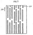
- FIG. 1 is a schematic view of a typical belted single-facer section 10 of a corrugated board production line.
- a core paper 12 previously exposed to steam, which makes it more pliable, is fed continuously between a pair of cooperating rolls 14, 16.
- the rolls 14,16 have uniformly spaced, peripheral teeth 18, 20, which mesh as the rolls 14, 16 rotate about their respective, parallel axes 22, 24.
- the meshing teeth 18, 20 produce corrugations 26 in the core paper 12.
- a coating mechanism 28 applies a starch paste 30 to the crests 32 of the corrugations 26 in the core paper 12.
- the corrugated core paper 12 is continuously applied to a liner paper 34 at point 36, where a belt 40, which is trained around a pair of spaced rollers 42, 44, passes around roller 42.
- the spaced rollers 42, 44 are so disposed that belt 40 bears against roll 16, and both may form nips with roll 16, so that the belt 40, trained thereabout, bears against roll 16 for the entire interval between spaced rollers 42, 44 forming an extended nip between roll 16 and belt 40.
- Heat is applied to the corrugated core paper 12 and liner paper 34 through at least one of the rollers 42, 44, belt 40 and roll 16. The heat vaporizes water absorbed by the corrugated core paper 12 when the corrugated core paper 12 was exposed to steam and dries the starch paste 30.
- the rollers 42, 44 are situated so that the teeth 20 on roll 16 bear against the outside surface of the belt 40 over a substantial circumferential extent as the system operates.
- the teeth 20 maintain the proper registration of the corrugated core paper 12 as it is advanced.
- the roll 16 firmly presses the side of the core paper 12 with the paste thereon against the liner paper 34 to effect bonding there between.
- the corrugated core paper 12 with the liner paper 34 attached thereto exits as a completed product 50 from between the roll 16 and the roller 44.
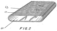
- a perspective view of the belt 40 is provided in Fig. 2 .
- the belt 40 has an inner surface 60 and an outer surface 62.
- the outer surface 62 is provided with a plurality of grooves 64 extending substantially in the machine direction around the belt 40.
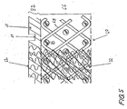
- Fig. 3 is a cross section of belt 40 taken as indicated by line 3--3 in Fig. 2 .
- the cross section is taken in the transverse, or cross-machine, direction of belt, and shows that belt includes a base structure 66.
- the base structure 66 may be woven from transverse, or cross-machine direction, yarns 68 and longitudinal, or machine-direction, yarns 70.
- Base structure 66 is depicted as having been woven flat, the transverse yarns 68 being weft yarns weaving over, under and between the stacked pairs of longitudinal warp yarns 70 in a duplex weave and joined to form an endless belt. It should be understood, however, that base structure 66 may be woven endless. It should be further understood that base structure 66 may be woven in a single-layer weave, or in any other weave suitable for the purpose.
- the base structure 66 may alternatively be a non-woven structure in the form of, for example, a mesh as in an assembly of transverse and longitudinal yarns, which may be bonded together at their mutual crossing points to form a fabric. Further, the base structure 66 may be a knitted or braided fabric, or a spiral-link belt of the type shown in U.S. Pat. No. 4,567,077 to Gauthier . The base structure 66 may also be extruded from a polymeric resin material in the form of a sheet or membrane, which may subsequently be provided with apertures.
- the base structure 66 may comprise non-woven mesh fabrics, such as those shown in commonly assigned U.S. Pat. No. 4,427,734 to Johnson .
- the base structure 66 may be produced by spirally winding a strip of woven, non-woven, knitted, mesh, or braided according to the methods shown in commonly assigned U.S. Pat. No. 5,360,656 to Rexfelt et al .
- the base structure 66 may accordingly comprise a spirally wound strip, wherein each spiral turn is joined to the next by a continuous seam making the base structure endless in a longitudinal direction.
- a belt 40 having a base structure 66 of this type is disclosed in commonly assigned U.S. Pat. Nos. 5,792,323 and 5,837,080 .
- One or more layers of this type can be utilized, again a seam optionally may be introduced for installation on the machine.
- the base structure 66 may be woven, or otherwise assembled, from warp yarns and weft yarns comprising yarns of any of the varieties used in the manufacture of paper machine clothing and industrial process fabrics. That is to say, the base structure 66 may include natural or metal yarns, monofilament, plied monofilament, multifilament, plied multifilament or yarns spun from staple fibers of any of the synthetic polymeric resins used by those skilled in the art in the manufacture of fabrics intended for use in high-temperature environments.
- the base structure 66 may be manufactured from yarns of the following materials: polyaramids, such as Nomex ®, and Kevlar®.; polyphenylene sulfide (PPS), which is more commonly known as Ryton®.; an aromatic polyester, which is commonly known as VECTRAN®; polyetheretherketone (PEEK); polyester and blends thereof.
- the base structure may comprise yarns of Kevlar® in the machine direction and Ryton® or polyester monofilament yarns in the cross-machine direction.
- the outer surface 62 of belt 40 that is, the surface which contacts the board may be formed by a polymeric resin coating 82, as shown in Figs. 3 and 4 .
- the inner surface 60 of belt 40 that is, the surface which slides over rollers 42 and 44 may also be formed by a polymeric resin coating, not shown.
- the belt 40 may be permeable or impermeable.
- grooves 64 can be cut into the polymeric resin coating and either have sufficient depth to extend past the depth of the resin coating 82 and into the base structure 66, as shown in Fig. 4 .
- the grooves of belt 40 can have a depth less than the thickness of the resin coating 82 to insure that the resin coating remains impermeable to fluid, as shown in Fig. 3 .
- a land area 65 separates the grooves from one another.
- the grooves 64 and land areas 65 may be of substantially equivalent widths, however, in the preferred embodiment the grooves are narrower than the land width, as shown in Figs. 3 and 4 .
- the grooves 64 may be provided by cutting a continuous single groove that spirals about the endless loop of the belt on the outer surface.
- the orientation of the resulting grooves 64 may deviate from the machine or longitudinal direction by a small angle.
- the provision of grooves 64 in this manner is contemplated by the inventor as falling within the scope of the invention.
- grooves 64 may alternatively be provided by cutting two continuous grooves which spiral about the endless loop of the belt 40 on outer surface 62 in opposite directions, that is, one describing a right-handed spiral and the other describing a left-handed spiral. Further, the grooves 64 need not be perfectly straight but may have some degree of curvature or waviness, or longitudinal direction by deviating no more than 45 degrees from there at any point, so long as they remain primarily oriented in the machine.
- grooves 64 need not be continuous in their longitudinal direction which may correspond to the machine direction of the belt. Rather, grooves 64 may have a length less than the length of the belt 40, such as approximately 1 ⁇ 4 of the length of the belt.
- grooves 64 may vary in accordance with the efficiency of the moisture removal and release characteristics.
- Figures 7-14 illustrate several arrangements of grooves.
- grooves 64 may be arranged in a equal number of rows wherein a line intersecting the ends of each groove in a row is substantially perpendicular to the longitudinal direction 100.
- the number of grooves in a row and distances between adjacent rows in the longitudinal direction on belt 40 may vary in accordance with the application, and/or the desired efficiency of the dewatering process.
- Grooves 64 are separated from one another by the land areas 65.
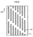
- Figure 8 is a top view of a belt 40 in accordance with another embodiment of the present invention.
- grooves 64 are formed in rows in the longitudinal direction of belt 40, in which a line intersecting the ends of each groove in a row is at an angle ⁇ to the transverse direction.
- Angle ⁇ may be 25-30°.
- Figure 9 is a top view of a belt 40 in accordance with another embodiment of the present invention.
- grooves 64 are formed in staggered rows.
- the length of groove 64 in the machine direction may be any length. Further, grooves 64 and land areas 65 may be arranged in any pattern that provides desirable moisture removal and release characteristics. Grooves 64 and land areas 65 are depicted in Figures 7-9 as being of different widths, although this need not be the case. Nevertheless, land areas 65 may be thought of as narrow pillars of cured polymeric resin aligned in the machine direction on outer surface 62 of the belt 40.
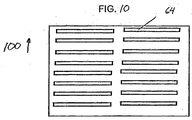
- the grooves have been described as running in a longitudinal or machine direction, the present invention is not so limited. That is, the grooves could be arranged in any other direction, such as in a transverse or CD direction, or in a direction which is at an angle ⁇ (such as 0 ⁇ ⁇ 90°) relative to the machine direction. In such situation, the "length" may be shorter than sides of the belt 40. Accordingly, the pattern of grooves 64 disclosed in Figures 7-9 may be applied to grooves running in these other directions as, for example, shown in Figures 10 and 11 .
- grooves 64 may be arranged in a number of columns wherein a line intersecting the ends of each groove in a column is substantially perpendicular to the transverse direction.
- the number of grooves in a column and distances between adjacent columns in the CD or transverse direction on belt 40 may vary in accordance with the application and/or the desired efficiency of the dewatering process.
- grooves 64 may be formed in a staggered pattern, such as in belt 40 shown in Figure 11 .
- the grooves 64 may be continuous in length in the transverse or CD direction, that is, such grooves may extend transversely from a first position located at or close to a first edge of the belt to a second position located at or close to the opposite edge of the belt.
- the present belt may have other patterns of non-continuous grooves.
- the present belt may have a number of first grooves (such as groove 102) and/or a number of second grooves (such as groove 104). Each of such grooves may have an overall length and width that is less than the borders of the belt 40.
- the present belt may have a plurality of grooves oriented in a first direction (such as the MD direction) wherein a number of such grooves are non-continuous grooves and a number of such grooves are continuous grooves.
- a belt 40 according to the present invention may include non-standard type continuous grooves.
- a belt 40 may have a number of continuous grooves 64 each having a straight portion followed by a zigzag portion 110 followed by another straight portion 64 and so forth.
- a belt 40 may have one or more grooves 64 each having a number of first portions 106 having a first width and a number of second portions 108 having a second width that is smaller than the first width.
- the present belt may have any other pattern or combination of continuous and/or non-continuous grooves oriented in any one or more directions wherein all or a relevant portion thereof is shorter than the borders of the arcuate pressure shoe.
- each groove is primarily utilized for moisture removal and release.
- the actual spacing, size, shape and/or depth of each groove may be determined by the desired characteristic.
- the shapes of the grooves utilized in the present belt may have a number of different cross-sectional shapes. Examples of several of such cross-sectional shapes are shown in Figures 15-20 .
- the shapes of the grooves of the present belt are not limited to these shapes.
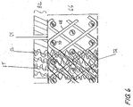
- the base structure 66 may be needled with a web 72 of staple fiber material in such a manner that some of the fibers are driven into the base structure as shown in Figs. 5 and 6 .
- One or more layers of staple fiber material may be needled into the base structure 66, and the web 72 may extend partially or completely there through.
- the web 72 of staple fiber material may also form a layer covering a surface of the base structure 66.
- the web is included in only a portion of Figs. 5 and 6 .
- the needled base structure may include grooves 64 and an impermeable resin layer 65.
- the resin layer may be permeable having grooves formed to the depth of the resin layer as shown in Fig. 6 .
- the staple fiber material needled into the base structure 66 may be any of the synthetic polymeric resins used by those skilled in the art in the manufacture of fabrics intended for use in high-temperature environments.
- the staple fiber material may comprise staple fibers of any of the following materials: polyaramids, such as Nomex® and Keylar®; polyphenylene sulfide (PPS), which is more commonly known as Ryton®; polyetheretherketone (PEEK); and polyester.
- the integrity and durability of the needled belt is further improved by coating the base structure 66 with a polymeric resin material 82.
- the coasting is providing a structure that is either impermeable or permeable.
- Coating materials include polymeric resins such polyurethane, polyethylene, polyamide, polyvinyl chloride, and ionomer resins sold under the trade name SURLYN®, those of skill in the art will understand that other resin materials could be used provided they provide sufficient frictional coefficients and impermeability to fluids.
- the grooves 64 may be formed into the outer surface 62 of the belt 40 that has been needled with fibers 72. After the belt being coated with a resin which is cured, the grooves 64 can be cut to either have sufficient depth to extend past the depth of the resin coating and into the base structure 66, or can be formed to a depth less than the thickness of the resin coating to insure that the resin coating remains impermeable to water.
- grooves 64 may be pressed into the outer surface 62 by an embossing device before the polymeric resin 82 has been cured, or may be molded into the belt 40 where it is manufactured using a molding process.
- a series of holes or vents could be drilled into the belt 40.
- These holes can be used in conjunction with any of the base structures 66 described herein.
- the holes can be formed to a depth equal to or greater than the thickness of the resin layer thus forming a permeable resin layer.
- the belt 40 may include fibers needled into the base to form a fibrous web according to the teachings of the grooved belt embodiments above. Still further, the holes can be formed to extend completely through the belt 40.
- both needled and un-needled resin coated belts can be manufactured with grooves or holes and result in superior separation of the belt 40 from the completed corrugated board, resulting in increased quality in the production of corrugated board.
- the resin layer may alternatively be permeable or impermeable depending upon the depth of the grooves and the application of the resin.
- a vented surface having either grooves or holes operates to remove moisture from the corrugated board. In the case of continuous grooves the moisture is vented directly to the atmosphere. In the case of discontinuous grooves or holes, these features act as temporary storage facilities that release the moisture to the atmosphere when outside the nip. So it should be understood that the surface 62 of the belt 40 is multifunctional in that it optimizes moisture venting and removal and provides for smooth sheet release after the nip.
Landscapes
- Engineering & Computer Science (AREA)
- Mechanical Engineering (AREA)
- Paper (AREA)
- Machines For Manufacturing Corrugated Board In Mechanical Paper-Making Processes (AREA)
- Laminated Bodies (AREA)
- Belt Conveyors (AREA)
- Advancing Webs (AREA)
- Treatments For Attaching Organic Compounds To Fibrous Goods (AREA)
- Structure Of Belt Conveyors (AREA)
Applications Claiming Priority (2)
| Application Number | Priority Date | Filing Date | Title |
|---|---|---|---|
| US10/720,902 US7654296B2 (en) | 2003-11-24 | 2003-11-24 | Grooved single facer belt |
| PCT/US2004/031236 WO2005056281A1 (en) | 2003-11-24 | 2004-09-23 | Grooved single facer corrugator belt |
Publications (2)
| Publication Number | Publication Date |
|---|---|
| EP1697118A1 EP1697118A1 (en) | 2006-09-06 |
| EP1697118B1 true EP1697118B1 (en) | 2016-04-13 |
Family
ID=34591677
Family Applications (1)
| Application Number | Title | Priority Date | Filing Date |
|---|---|---|---|
| EP04784895.7A Expired - Lifetime EP1697118B1 (en) | 2003-11-24 | 2004-09-23 | Grooved single facer corrugator belt |
Country Status (13)
| Country | Link |
|---|---|
| US (1) | US7654296B2 (https=) |
| EP (1) | EP1697118B1 (https=) |
| JP (1) | JP4674867B2 (https=) |
| KR (1) | KR20060111614A (https=) |
| CN (1) | CN1886252A (https=) |
| AU (1) | AU2004297155A1 (https=) |
| BR (1) | BRPI0416413B1 (https=) |
| CA (1) | CA2546374C (https=) |
| MX (1) | MXPA06005877A (https=) |
| NO (1) | NO20062976L (https=) |
| RU (1) | RU2356739C2 (https=) |
| TW (1) | TWI331562B (https=) |
| WO (1) | WO2005056281A1 (https=) |
Families Citing this family (12)
| Publication number | Priority date | Publication date | Assignee | Title |
|---|---|---|---|---|
| ITMI20050123A1 (it) * | 2005-01-28 | 2006-07-29 | Feltri Marone S P A | Nastro corrugatore di supporto-trasporto di cartone ondulato in una macchina ondulatrice |
| JP4477025B2 (ja) * | 2007-03-12 | 2010-06-09 | イチカワ株式会社 | 抄紙用シュープレスベルト |
| JP4972438B2 (ja) * | 2007-03-22 | 2012-07-11 | イチカワ株式会社 | 抄紙用シュープレスベルト |
| KR100868727B1 (ko) * | 2007-07-18 | 2008-11-13 | 주식회사 보우 | 편면 골판지 제조기용 가압벨트식 엔드레스 벨트 |
| NZ568698A (en) | 2008-05-27 | 2010-12-24 | Corcel Ip Ltd | Method and machine for forming single face corrugated board |
| EP2376690B1 (en) * | 2008-12-12 | 2016-08-31 | Albany International Corp. | Industrial fabric including spirally wound material strips |
| CN102472363A (zh) * | 2009-07-02 | 2012-05-23 | 盖茨公司 | 改善的用于齿动力传动带的织物和带 |
| MX348400B (es) * | 2010-03-31 | 2017-06-09 | Corcel Ip Ltd * | Método y aparato mejorado para formar un cartón corrugado. |
| FI20115099A7 (fi) * | 2011-01-31 | 2012-08-01 | Metso Fabrics Oy | Kenkäpuristinhihna, menetelmä sen valmistamiseksi ja käyttö kenkäpuristimessa |
| TWI810666B (zh) * | 2020-03-30 | 2023-08-01 | 台灣龍盟複合材料股份有限公司 | 防水瓦楞紙 |
| TWI791146B (zh) | 2020-03-30 | 2023-02-01 | 台灣龍盟複合材料股份有限公司 | 防水瓦楞紙、其製造方法、其製造設備及其用途 |
| JP7695648B2 (ja) * | 2021-12-24 | 2025-06-19 | レンゴー株式会社 | 半切罫線入り片面段ボールの製造方法 |
Family Cites Families (29)
| Publication number | Priority date | Publication date | Assignee | Title |
|---|---|---|---|---|
| US3368933A (en) * | 1963-11-15 | 1968-02-13 | Huyck Corp | Corrugator combiner machine |
| SE310693B (https=) * | 1963-12-16 | 1969-05-12 | Grace W R & Co | |
| FR2494318B1 (fr) * | 1980-11-14 | 1986-10-10 | Feutres Papeteries Tissus Indl | Bande constituee de spirales |
| US4427734A (en) * | 1982-04-19 | 1984-01-24 | Albany International Corp. | Wet press felt for papermaking machines |
| JPS5954598U (ja) * | 1982-10-01 | 1984-04-10 | 市川毛織株式会社 | 抄紙機の広巾ニツププレス用加圧ベルト |
| JPH059152Y2 (https=) * | 1986-12-09 | 1993-03-08 | ||
| US4973383A (en) | 1989-08-11 | 1990-11-27 | Beloit Corporation | Bearing blanket for an extended nip press |
| US4946731A (en) * | 1989-09-28 | 1990-08-07 | Albany International Corp. | Construction for an extended nip press belt |
| JP2889341B2 (ja) * | 1990-09-07 | 1999-05-10 | ヤマウチ株式会社 | 脱水プレス用ベルト |
| SE468602B (sv) * | 1990-12-17 | 1993-02-15 | Albany Int Corp | Pressfilt samt saett att framstaella densamma |
| US5196092A (en) * | 1991-09-25 | 1993-03-23 | Albany International Corp. | Reinforcement of coated surfaces of lnp belts |
| US5208087A (en) * | 1991-10-08 | 1993-05-04 | Albany International Corp. | Spiral construction for a long nip press belt |
| NZ272169A (en) * | 1994-06-09 | 1997-06-24 | Albany Int Corp | Transfer belt for papermaking machine: seam construction: pintles passed through seaming loops |
| DE9414344U1 (de) * | 1994-09-03 | 1994-10-20 | Mühlen Sohn GmbH & Co., 89134 Blaustein | Gewebter Gurt für eine Wellpappenmaschine |
| DE4438354A1 (de) * | 1994-10-27 | 1996-05-02 | Voith Sulzer Papiermasch Gmbh | Preßmantel und Verfahren zur Herstellung eines Preßmantels |
| US5857605A (en) * | 1995-06-26 | 1999-01-12 | Marquip, Inc. | Vacuum assisted web drive for corrugator double backer |
| US5792323A (en) * | 1995-09-07 | 1998-08-11 | Albany International Corp. | Spiral base structres for long nip paper machine press belts |
| US6186209B1 (en) * | 1996-10-29 | 2001-02-13 | Albany International Corp. | Impermeable corrugator belt for application on air bearing pressure zones of a corrugator machine |
| US5732749A (en) * | 1997-02-14 | 1998-03-31 | Albany International Corp. | Pin seam for laminated integrally woven papermaker's fabric |
| DE19716716C2 (de) | 1997-04-21 | 2002-04-18 | Bhs Corr Masch & Anlagenbau | Heizvorrichtung für eine Wellpappenanlage |
| US6027615A (en) * | 1997-05-06 | 2000-02-22 | Albany International Corp. | Belts for compliant calendering |
| US6276420B1 (en) * | 1998-04-17 | 2001-08-21 | Albany International Corp. | Coated corrugator belt |
| ES2235349T3 (es) * | 1998-04-22 | 2005-07-01 | Albany International Corp. | Cinta impregnada en resina que tiene una superficie externa texturizada para aplicacion en maquinas de fabricacion de papel. |
| US6465074B1 (en) * | 1999-08-25 | 2002-10-15 | Albany International Corp. | Base substrates for coated belts |
| US6231928B1 (en) * | 1999-08-30 | 2001-05-15 | Albany International Corp. | Method for manufacturing resin-impregnated endless belt structures for papermaking machines and similar industrial applications |
| US6470944B1 (en) * | 1999-10-20 | 2002-10-29 | Albany International Corp. | Woven endless and needlepunched corrugator single facer belt |
| US6428874B1 (en) * | 2000-11-03 | 2002-08-06 | Albany International Corp. | Grooved long nip shoe press belt |
| US6630223B2 (en) * | 2001-01-26 | 2003-10-07 | Albany International Corp. | Spirally wound shaped yarns for paper machine clothing and industrial belts |
| EP1412571A1 (de) | 2001-08-02 | 2004-04-28 | Mühlen Sohn GmbH & Co. | Gewebegurt für eine wellpappenbeklebemaschine |
-
2003
- 2003-11-24 US US10/720,902 patent/US7654296B2/en not_active Expired - Fee Related
-
2004
- 2004-09-23 RU RU2006117330/12A patent/RU2356739C2/ru not_active IP Right Cessation
- 2004-09-23 CN CNA2004800347562A patent/CN1886252A/zh active Pending
- 2004-09-23 MX MXPA06005877A patent/MXPA06005877A/es active IP Right Grant
- 2004-09-23 CA CA2546374A patent/CA2546374C/en not_active Expired - Fee Related
- 2004-09-23 EP EP04784895.7A patent/EP1697118B1/en not_active Expired - Lifetime
- 2004-09-23 KR KR1020067012595A patent/KR20060111614A/ko not_active Ceased
- 2004-09-23 JP JP2006541136A patent/JP4674867B2/ja not_active Expired - Fee Related
- 2004-09-23 BR BRPI0416413-0A patent/BRPI0416413B1/pt not_active IP Right Cessation
- 2004-09-23 WO PCT/US2004/031236 patent/WO2005056281A1/en not_active Ceased
- 2004-09-23 AU AU2004297155A patent/AU2004297155A1/en not_active Abandoned
- 2004-09-30 TW TW093129577A patent/TWI331562B/zh not_active IP Right Cessation
-
2006
- 2006-06-26 NO NO20062976A patent/NO20062976L/no not_active Application Discontinuation
Also Published As
| Publication number | Publication date |
|---|---|
| US20050112332A1 (en) | 2005-05-26 |
| CA2546374C (en) | 2012-12-04 |
| WO2005056281A1 (en) | 2005-06-23 |
| NO20062976L (no) | 2006-08-24 |
| EP1697118A1 (en) | 2006-09-06 |
| JP4674867B2 (ja) | 2011-04-20 |
| TWI331562B (en) | 2010-10-11 |
| AU2004297155A1 (en) | 2005-06-23 |
| KR20060111614A (ko) | 2006-10-27 |
| AU2004297155A2 (en) | 2005-06-23 |
| US7654296B2 (en) | 2010-02-02 |
| JP2007521167A (ja) | 2007-08-02 |
| TW200517256A (en) | 2005-06-01 |
| RU2356739C2 (ru) | 2009-05-27 |
| MXPA06005877A (es) | 2006-09-04 |
| CA2546374A1 (en) | 2005-06-23 |
| BRPI0416413A (pt) | 2007-01-09 |
| BRPI0416413B1 (pt) | 2017-07-04 |
| RU2006117330A (ru) | 2008-01-10 |
| CN1886252A (zh) | 2006-12-27 |
Similar Documents
| Publication | Publication Date | Title |
|---|---|---|
| US6630223B2 (en) | Spirally wound shaped yarns for paper machine clothing and industrial belts | |
| EP2938780B1 (en) | Industrial fabric comprising spirally wound material strips and method of making thereof | |
| JP3511227B2 (ja) | 一体として織られる対になった異なる機械方向の糸を有する抄紙機の布 | |
| EP1697118B1 (en) | Grooved single facer corrugator belt | |
| JP3991154B2 (ja) | 溝付き長尺ニップシュープレスベルト | |
| AU2002236878A1 (en) | Spirally wound shaped yarns for paper machine clothing and industrial belts | |
| JP2001040595A (ja) | 成型糸を有している多軸プレス布 | |
| CA2269196C (en) | Coated corrugator belt | |
| JP2007521167A5 (https=) | ||
| CN102277771A (zh) | 具有沟槽表面的靴形压榨带 | |
| JP2011522136A (ja) | 表面に溝があるシュープレスベルト | |
| CA2546379C (en) | Metal spiral fabrics for corrugator machines |
Legal Events
| Date | Code | Title | Description |
|---|---|---|---|
| PUAI | Public reference made under article 153(3) epc to a published international application that has entered the european phase |
Free format text: ORIGINAL CODE: 0009012 |
|
| 17P | Request for examination filed |
Effective date: 20060608 |
|
| AK | Designated contracting states |
Kind code of ref document: A1 Designated state(s): AT BE BG CH CY CZ DE DK EE ES FI FR GB GR HU IE IT LI LU MC NL PL PT RO SE SI SK TR |
|
| DAX | Request for extension of the european patent (deleted) | ||
| 17Q | First examination report despatched |
Effective date: 20150320 |
|
| GRAP | Despatch of communication of intention to grant a patent |
Free format text: ORIGINAL CODE: EPIDOSNIGR1 |
|
| INTG | Intention to grant announced |
Effective date: 20151112 |
|
| GRAS | Grant fee paid |
Free format text: ORIGINAL CODE: EPIDOSNIGR3 |
|
| GRAA | (expected) grant |
Free format text: ORIGINAL CODE: 0009210 |
|
| RAP1 | Party data changed (applicant data changed or rights of an application transferred) |
Owner name: ALBANY INTERNATIONAL CORP. |
|
| AK | Designated contracting states |
Kind code of ref document: B1 Designated state(s): AT BE BG CH CY CZ DE DK EE ES FI FR GB GR HU IE IT LI LU MC NL PL PT RO SE SI SK TR |
|
| REG | Reference to a national code |
Ref country code: GB Ref legal event code: FG4D |
|
| REG | Reference to a national code |
Ref country code: AT Ref legal event code: REF Ref document number: 789658 Country of ref document: AT Kind code of ref document: T Effective date: 20160415 Ref country code: CH Ref legal event code: NV Representative=s name: BUGNION S.A., CH Ref country code: CH Ref legal event code: EP |
|
| REG | Reference to a national code |
Ref country code: IE Ref legal event code: FG4D |
|
| REG | Reference to a national code |
Ref country code: DE Ref legal event code: R096 Ref document number: 602004049060 Country of ref document: DE |
|
| REG | Reference to a national code |
Ref country code: SE Ref legal event code: TRGR |
|
| REG | Reference to a national code |
Ref country code: NL Ref legal event code: FP |
|
| REG | Reference to a national code |
Ref country code: FR Ref legal event code: PLFP Year of fee payment: 13 |
|
| PG25 | Lapsed in a contracting state [announced via postgrant information from national office to epo] |
Ref country code: PL Free format text: LAPSE BECAUSE OF FAILURE TO SUBMIT A TRANSLATION OF THE DESCRIPTION OR TO PAY THE FEE WITHIN THE PRESCRIBED TIME-LIMIT Effective date: 20160413 |
|
| PGFP | Annual fee paid to national office [announced via postgrant information from national office to epo] |
Ref country code: NL Payment date: 20160926 Year of fee payment: 13 Ref country code: GB Payment date: 20160927 Year of fee payment: 13 Ref country code: FI Payment date: 20160927 Year of fee payment: 13 Ref country code: CH Payment date: 20160927 Year of fee payment: 13 |
|
| PG25 | Lapsed in a contracting state [announced via postgrant information from national office to epo] |
Ref country code: GR Free format text: LAPSE BECAUSE OF FAILURE TO SUBMIT A TRANSLATION OF THE DESCRIPTION OR TO PAY THE FEE WITHIN THE PRESCRIBED TIME-LIMIT Effective date: 20160714 Ref country code: ES Free format text: LAPSE BECAUSE OF FAILURE TO SUBMIT A TRANSLATION OF THE DESCRIPTION OR TO PAY THE FEE WITHIN THE PRESCRIBED TIME-LIMIT Effective date: 20160413 Ref country code: PT Free format text: LAPSE BECAUSE OF FAILURE TO SUBMIT A TRANSLATION OF THE DESCRIPTION OR TO PAY THE FEE WITHIN THE PRESCRIBED TIME-LIMIT Effective date: 20160816 |
|
| PGFP | Annual fee paid to national office [announced via postgrant information from national office to epo] |
Ref country code: CZ Payment date: 20160909 Year of fee payment: 13 Ref country code: AT Payment date: 20160901 Year of fee payment: 13 Ref country code: SE Payment date: 20160928 Year of fee payment: 13 Ref country code: FR Payment date: 20160926 Year of fee payment: 13 |
|
| PGFP | Annual fee paid to national office [announced via postgrant information from national office to epo] |
Ref country code: BE Payment date: 20160927 Year of fee payment: 13 |
|
| REG | Reference to a national code |
Ref country code: DE Ref legal event code: R097 Ref document number: 602004049060 Country of ref document: DE |
|
| PG25 | Lapsed in a contracting state [announced via postgrant information from national office to epo] |
Ref country code: RO Free format text: LAPSE BECAUSE OF FAILURE TO SUBMIT A TRANSLATION OF THE DESCRIPTION OR TO PAY THE FEE WITHIN THE PRESCRIBED TIME-LIMIT Effective date: 20160413 Ref country code: DK Free format text: LAPSE BECAUSE OF FAILURE TO SUBMIT A TRANSLATION OF THE DESCRIPTION OR TO PAY THE FEE WITHIN THE PRESCRIBED TIME-LIMIT Effective date: 20160413 Ref country code: SK Free format text: LAPSE BECAUSE OF FAILURE TO SUBMIT A TRANSLATION OF THE DESCRIPTION OR TO PAY THE FEE WITHIN THE PRESCRIBED TIME-LIMIT Effective date: 20160413 Ref country code: EE Free format text: LAPSE BECAUSE OF FAILURE TO SUBMIT A TRANSLATION OF THE DESCRIPTION OR TO PAY THE FEE WITHIN THE PRESCRIBED TIME-LIMIT Effective date: 20160413 |
|
| PGFP | Annual fee paid to national office [announced via postgrant information from national office to epo] |
Ref country code: DE Payment date: 20160928 Year of fee payment: 13 |
|
| PLBE | No opposition filed within time limit |
Free format text: ORIGINAL CODE: 0009261 |
|
| STAA | Information on the status of an ep patent application or granted ep patent |
Free format text: STATUS: NO OPPOSITION FILED WITHIN TIME LIMIT |
|
| PGFP | Annual fee paid to national office [announced via postgrant information from national office to epo] |
Ref country code: IT Payment date: 20160923 Year of fee payment: 13 |
|
| 26N | No opposition filed |
Effective date: 20170116 |
|
| PG25 | Lapsed in a contracting state [announced via postgrant information from national office to epo] |
Ref country code: MC Free format text: LAPSE BECAUSE OF FAILURE TO SUBMIT A TRANSLATION OF THE DESCRIPTION OR TO PAY THE FEE WITHIN THE PRESCRIBED TIME-LIMIT Effective date: 20160413 |
|
| PG25 | Lapsed in a contracting state [announced via postgrant information from national office to epo] |
Ref country code: SI Free format text: LAPSE BECAUSE OF FAILURE TO SUBMIT A TRANSLATION OF THE DESCRIPTION OR TO PAY THE FEE WITHIN THE PRESCRIBED TIME-LIMIT Effective date: 20160413 |
|
| REG | Reference to a national code |
Ref country code: IE Ref legal event code: MM4A |
|
| PG25 | Lapsed in a contracting state [announced via postgrant information from national office to epo] |
Ref country code: IE Free format text: LAPSE BECAUSE OF NON-PAYMENT OF DUE FEES Effective date: 20160923 |
|
| PG25 | Lapsed in a contracting state [announced via postgrant information from national office to epo] |
Ref country code: LU Free format text: LAPSE BECAUSE OF NON-PAYMENT OF DUE FEES Effective date: 20160923 |
|
| REG | Reference to a national code |
Ref country code: AT Ref legal event code: UEP Ref document number: 789658 Country of ref document: AT Kind code of ref document: T Effective date: 20160413 |
|
| REG | Reference to a national code |
Ref country code: DE Ref legal event code: R119 Ref document number: 602004049060 Country of ref document: DE |
|
| PG25 | Lapsed in a contracting state [announced via postgrant information from national office to epo] |
Ref country code: FI Free format text: LAPSE BECAUSE OF NON-PAYMENT OF DUE FEES Effective date: 20170923 Ref country code: CZ Free format text: LAPSE BECAUSE OF NON-PAYMENT OF DUE FEES Effective date: 20170923 |
|
| REG | Reference to a national code |
Ref country code: CH Ref legal event code: PL |
|
| REG | Reference to a national code |
Ref country code: SE Ref legal event code: EUG |
|
| REG | Reference to a national code |
Ref country code: NL Ref legal event code: MM Effective date: 20171001 |
|
| REG | Reference to a national code |
Ref country code: AT Ref legal event code: MM01 Ref document number: 789658 Country of ref document: AT Kind code of ref document: T Effective date: 20170923 |
|
| GBPC | Gb: european patent ceased through non-payment of renewal fee |
Effective date: 20170923 |
|
| PG25 | Lapsed in a contracting state [announced via postgrant information from national office to epo] |
Ref country code: HU Free format text: LAPSE BECAUSE OF FAILURE TO SUBMIT A TRANSLATION OF THE DESCRIPTION OR TO PAY THE FEE WITHIN THE PRESCRIBED TIME-LIMIT; INVALID AB INITIO Effective date: 20040923 Ref country code: CY Free format text: LAPSE BECAUSE OF FAILURE TO SUBMIT A TRANSLATION OF THE DESCRIPTION OR TO PAY THE FEE WITHIN THE PRESCRIBED TIME-LIMIT Effective date: 20160413 |
|
| REG | Reference to a national code |
Ref country code: BE Ref legal event code: FP Effective date: 20160705 Ref country code: BE Ref legal event code: MM Effective date: 20170930 |
|
| PG25 | Lapsed in a contracting state [announced via postgrant information from national office to epo] |
Ref country code: TR Free format text: LAPSE BECAUSE OF FAILURE TO SUBMIT A TRANSLATION OF THE DESCRIPTION OR TO PAY THE FEE WITHIN THE PRESCRIBED TIME-LIMIT Effective date: 20160413 Ref country code: NL Free format text: LAPSE BECAUSE OF NON-PAYMENT OF DUE FEES Effective date: 20171001 |
|
| REG | Reference to a national code |
Ref country code: FR Ref legal event code: ST Effective date: 20180531 |
|
| PG25 | Lapsed in a contracting state [announced via postgrant information from national office to epo] |
Ref country code: BG Free format text: LAPSE BECAUSE OF FAILURE TO SUBMIT A TRANSLATION OF THE DESCRIPTION OR TO PAY THE FEE WITHIN THE PRESCRIBED TIME-LIMIT Effective date: 20160413 Ref country code: CH Free format text: LAPSE BECAUSE OF NON-PAYMENT OF DUE FEES Effective date: 20170930 Ref country code: DE Free format text: LAPSE BECAUSE OF NON-PAYMENT OF DUE FEES Effective date: 20180404 Ref country code: GB Free format text: LAPSE BECAUSE OF NON-PAYMENT OF DUE FEES Effective date: 20170923 Ref country code: LI Free format text: LAPSE BECAUSE OF NON-PAYMENT OF DUE FEES Effective date: 20170930 |
|
| PG25 | Lapsed in a contracting state [announced via postgrant information from national office to epo] |
Ref country code: FR Free format text: LAPSE BECAUSE OF NON-PAYMENT OF DUE FEES Effective date: 20171002 Ref country code: AT Free format text: LAPSE BECAUSE OF NON-PAYMENT OF DUE FEES Effective date: 20170923 Ref country code: BE Free format text: LAPSE BECAUSE OF NON-PAYMENT OF DUE FEES Effective date: 20170930 Ref country code: IT Free format text: LAPSE BECAUSE OF NON-PAYMENT OF DUE FEES Effective date: 20170923 |
|
| PG25 | Lapsed in a contracting state [announced via postgrant information from national office to epo] |
Ref country code: SE Free format text: LAPSE BECAUSE OF NON-PAYMENT OF DUE FEES Effective date: 20170924 |