EP1696159A1 - Quetschventil - Google Patents
Quetschventil Download PDFInfo
- Publication number
- EP1696159A1 EP1696159A1 EP06101676A EP06101676A EP1696159A1 EP 1696159 A1 EP1696159 A1 EP 1696159A1 EP 06101676 A EP06101676 A EP 06101676A EP 06101676 A EP06101676 A EP 06101676A EP 1696159 A1 EP1696159 A1 EP 1696159A1
- Authority
- EP
- European Patent Office
- Prior art keywords
- housing
- section
- valve
- pinch valve
- passage cross
- Prior art date
- Legal status (The legal status is an assumption and is not a legal conclusion. Google has not performed a legal analysis and makes no representation as to the accuracy of the status listed.)
- Granted
Links
Images


Classifications
-
- F—MECHANICAL ENGINEERING; LIGHTING; HEATING; WEAPONS; BLASTING
- F16—ENGINEERING ELEMENTS AND UNITS; GENERAL MEASURES FOR PRODUCING AND MAINTAINING EFFECTIVE FUNCTIONING OF MACHINES OR INSTALLATIONS; THERMAL INSULATION IN GENERAL
- F16K—VALVES; TAPS; COCKS; ACTUATING-FLOATS; DEVICES FOR VENTING OR AERATING
- F16K7/00—Diaphragm valves or cut-off apparatus, e.g. with a member deformed, but not moved bodily, to close the passage ; Pinch valves
- F16K7/02—Diaphragm valves or cut-off apparatus, e.g. with a member deformed, but not moved bodily, to close the passage ; Pinch valves with tubular diaphragm
- F16K7/04—Diaphragm valves or cut-off apparatus, e.g. with a member deformed, but not moved bodily, to close the passage ; Pinch valves with tubular diaphragm constrictable by external radial force
- F16K7/07—Diaphragm valves or cut-off apparatus, e.g. with a member deformed, but not moved bodily, to close the passage ; Pinch valves with tubular diaphragm constrictable by external radial force by means of fluid pressure
Definitions
- the present invention relates to a pinch valve.
- Valves generally serve the temporary termination or throttling of a material or product stream. In principle, all gases, vapors or liquids but also granules, pasty materials and other materials come into question as a product stream. In other words, a valve is an actuator.
- Pinch valves in particular have a housing having an inlet opening, an outlet opening and a control opening for connection to a pressure medium.
- the inlet and outlet openings are connected to one another via a passage.
- the valve sleeve by applying a pressure medium, for.
- valve channel opens due to the elastic material properties of the valve sleeve and / or the pressure of the product flow again.
- the passageway formed by the housing generally has at least two sections of different cross-section. This has the advantage that in general a completely free passage can be formed in a pressureless state, so that almost no pressure loss occurs through the use of a pinch valve.
- the passage section with a larger passage cross-section forms outside the valve sleeve a control chamber which can be pressurized to close or throttle the valve via the control port with pressure.
- passage cross-section does not necessarily have to be circular. If in the context of this application of a larger or smaller passage cross section is mentioned, it is basically meant the passage cross-sectional area.
- the pinch valve can be used, for example, for metering or controlling liquids, suspensions, granules, pastes and other substances.
- a squeeze valve can also provide a perfect seal when using granules, powders or pastes.
- the known pinch valves are often made of metallic materials, wherein the valve body or the valve housing must be made due to the "bulging" construction by means of machining.
- Alternative manufacturing methods use, for example, chill casting, cold pressing or welding.
- chill casting, cold pressing or welding are very expensive and therefore associated with high costs.
- the housing is formed at least two parts, wherein the one housing part forms the portion with a smaller passage cross-section and the other housing part the portion with a larger passage cross-section.
- the division of the housing thus takes place substantially in the transverse and not in the longitudinal direction.
- the multi-part design of the housing such that the division takes place in sections, has the advantage that the individual parts without “bulges” or undercuts can be formed. This makes it possible to manufacture the housing without machining, which results in significant savings in manufacturing costs.
- the housing has at least three sections, one with a larger passage cross section and two with a smaller passage cross section, wherein the sections with a smaller passage cross section are preferably arranged in the region of the inlet and outlet openings.
- the housing split in such a way that one housing part forms a section with a smaller passage cross section and a section with a larger passage cross section, while the other housing part forms a housing section with a smaller passage cross section.
- the housing is formed at least three parts, wherein two housing parts form the portions with a smaller passage cross section and the third housing part forms the portion with a larger passage cross-section.
- the housing consists of a substantially cylindrical housing main part and at least one press zone ring, wherein the press zone ring is at least partially inserted into the housing main body.
- the cylindrical housing main part then forms the section with a larger passage cross section, while the press zone ring inserted into the housing main part forms the housing section with a smaller passage cross section.
- valve channel formed by the valve sleeve in the pressureless state of the control connection between the inlet and outlet opening has a substantially constant channel cross-section.
- the control opening is preferably located in the region of the housing section with a larger passage cross-section.
- Characterized a control chamber is formed between the valve sleeve on the one hand and the inner wall of the housing portion with a larger passage cross-section, which can be pressurized by acting on the control port with a pressure medium and compresses the valve sleeve so that the valve channel cross-section closes or at least reduced.
- a substantially annular control or functional space which can be acted upon via the control port with pressure. Due to the annular design of the functional space, a reliable and reproducible control of the valve sleeve is ensured by the pressurization.
- At least the housing part, which forms the section with a smaller passage cross section made of plastic, preferably of thermoplastic material, more preferably of a polyoxymethylene homo- or copolymer.
- the entire housing from plastic, preferably from thermoplastic material, more preferably from a polyoxymethylene homo- or - copolymer.
- thermoplastic material more preferably from a polyoxymethylene homo- or - copolymer.
- preparation of POM has proven to be particularly advantageous.
- the individual housing parts are sealed against each other, for example by means of an O-ring.
- the pressing zone ring has a flange which bears against the front of the housing main part.
- at least one housing or sleeve cover is provided with a lid opening for placement on the input or output port, wherein preferably the housing cover with a housing part, for example, the housing main part, can be screwed.
- This screwing can be done for example by means of self-tapping screws that can be screwed into corresponding holes in a housing part.
- This has the advantage that in the manufacture of the housing part in which the screws are to engage, no thread must be cut, but only a corresponding hole must be introduced. By this measure, it is possible to produce all housing parts, for example by injection molding. The necessary thread is then formed by using the self-tapping screws during the screwing of the housing cover with the corresponding housing part.
- the housing cover has a substantially flat lid base and an adjoining substantially cylindrical extension with a conical outer surface.
- the press zone ring at least partially has a substantially conical inner surface which corresponds to the conical outer surface of the cylindrical extension such that the valve sleeve between the cone-shaped outer surface of the cylindrical extension on the one hand and conical inner surface of the press zone ring on the other hand can be clamped.
- cone-shaped inner surface and / or the cone-shaped outer surface also formed stepped, i. can consist of several sections with different inner or Au ⁇ en pressmessern.
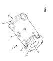
- FIG. 1 shows a perspective view of a pinch valve 1 according to the present invention.
- the pinch valve 1 has an inlet opening 2 and an outlet opening 3 and a control opening 4.
- the inlet opening 2 and the outlet opening 3 are connected to one another via a valve collar 16 (shown only in FIG. 4). If the control port 4 is acted upon by a pressure medium, for example in the form of compressed air, the valve sleeve 16 is compressed, and the channel cross-section between the inlet opening 2 and the outlet opening 3 is closed or at least reduced.
- the pinch valve 1 has a housing main part 5, two press zone rings 6 and two sleeve cover 7.
- the pinch valve 1 consists of a substantially cylindrical housing main part 5, in each of which a press zone ring 6 is inserted at the front ends.
- the press zone ring 6 also has a substantially cylindrical shape and has a flange 13.
- the pressing zone ring is designed such that it can be inserted into the frontal openings of the housing main part 5.
- an O-ring 9 is provided, which on the other hand bears against the housing main part 5 on the one side and against the flange 13 of the press zone ring 6 on the other side.
- the pressing zone ring 6 is fastened to the housing main part 5 with the aid of the sleeve cover 7.
- the sleeve covers 7 have a lid base surface and a conical extension 14 extending therefrom. In the cover base surface of the lid 7 bores are introduced, through which the screws 8 engage in corresponding bores 10 in the housing main part 5.
- the screws 8 are here designed as self-tapping screws, so that after the press zone ring 6 has been inserted with the interposition of the O-ring 9 in the frontal openings of the housing main body 5, the cover 7 can be inserted into the press zone ring 6 and with the help of self-tapping Screws 8, which engage through the holes in the lid 7 in the holes in the housing main body 5, can be screwed with this.
- This embodiment has the advantage that all parts of the housing can be made without great effort, for example by means of injection molding, since - in contrast to the valve housings of the prior art - no housing part has an undercut. Injection molding is a very economical process since finishing on the demoulded moldings is usually unnecessary.
- FIG. 3 shows a perspective sectional view of the pinch valve according to the invention.
- the pressing zone ring 6 has a substantially cylindrical outer surface.
- the inner surface of the press zone ring 6 widens both in the direction of the housing main part 5 and in the direction of the inlet or outlet opening.
- the widening inner surface of the Presszonenrings 6 substantially corresponds to the conical outer surface of the conical extension 14 of the housing cover 7, so that the valve sleeve (not shown) between the outer surface of the conical extension 14 of the housing cover 7 on the one hand and the flared inner surface 15 of the press zone ring 6 can be trapped.
- conical surfaces can also be formed stepped, as shown in Figure 3 the example of the flared inner surface 15 of the press zone ring 6 is. It is only essential that the two surfaces are formed such that when the housing cover 7, the valve sleeve is securely held between the housing cover and press zone ring 6.
- the illustrated, stepped embodiment has the advantage that the valve sleeve 16 can be kept very firm even when subjected to higher pressures.
- the Au ⁇ en decoration the conical projection 14 may be formed stepped, but it has been found that when mounting the valve, it is advantageous if the conical extension 14 has no steps, since then the socket cover 7 easier in the valve sleeve 16th and the press zone ring 6 can be used.
- the inner surface of the press zone ring 6 also widens in the direction of the housing main part. This has the advantage that, if in the unpressurized state, i. if the control port is not pressurized, the valve cuff bulges due to the product flow pressure, there is no damage to the valve sleeve, when it comes into contact with a sharp corner of the press zone 6 ring.
- the pinch valve 1 has a housing section 12 with a larger passage cross section d 2 and two housing sections 11 with a smaller passage cross section d 1 .
- valve sleeve 16 can be mounted such that a valve channel is formed, which has a substantially constant channel cross-section.
- FIG. 4 shows a further longitudinal section through the pinch valve. This figure differs from Figure 3 only in that now the valve sleeve 16 is shown. In this illustration, it is clear that there is a substantially annular control chamber 17 between the valve sleeve 16 and the inner wall of the housing portion with a larger passage cross-section.
Landscapes
- Engineering & Computer Science (AREA)
- General Engineering & Computer Science (AREA)
- Physics & Mathematics (AREA)
- Fluid Mechanics (AREA)
- Mechanical Engineering (AREA)
- Valve Housings (AREA)
- Lift Valve (AREA)
Abstract
Description
- Die vorliegende Erfindung betrifft ein Quetschventil. Ventile dienen im allgemeinen dem zeitweiligen Abschließen oder Drosseln eines Material- bzw. Produktstromes. Als Produktstrom kommen prinzipiell alle Gase, Dämpfe oder Flüssigkeiten aber auch Granulate, pastöse Massen und andere Materialien in Frage. Mit anderen Worten ist ein Ventil ein Stellglied.
- Quetschventile weisen im besonderen ein Gehäuse auf, das eine Eingangsöffnung, eine Ausgangsöffnung und eine Steueröffnung für die Verbindung mit einem Druckmedium hat. Dabei sind Eingangs- und Ausgangsöffnung über einen Durchlaß miteinander verbunden. Innerhalb des Gehäuses ist eine Ventilmanschette, z. B. ein Elastomerschlauch, angeordnet, die mit der Eingangs- und der Ausgangsöffnung verbunden und derart angeordnet ist, daß sie zwischen Eingangs- und Ausgangsöffnung einen Ventilkanal bildet, wobei bei Beaufschlagung der Steueröffnung mit einem Druckmedium sich die Ventilmanschette derart bewegt, daß der Kanalquerschnitt zwischen Eingangs- und Ausgangsöffnung verschlossen oder zumindest verringert wird. Mit anderen Worten kann die Ventilmanschette durch Anlegen eines Druckmediums, z. B. Druckluft, an die Steueröffnung derart zusammengedrückt werden, daß sich der Manschettenquerschnitt verschließt oder zumindest verringert, so daß der Produktstrom durch den Ventilkanal unterbunden oder zumindest gedrosselt wird. Wird dann die Steueröffnung wieder entlastet, so öffnet sich der Ventil kanal aufgrund der elastischen Materialeigenschaften der Ventilmanschette und/oder dem Druck des Produktstromes wieder.
- Der von dem Gehäuse gebildete Durchlaß weist im allgemeinen zumindest zwei Abschnitte mit unterschiedlichem Querschnitt auf. Dies hat den Vorteil, daß im allgemeinen bei drucklosem Zustand ein vollkommen freier Durchgang gebildet werden kann, so daß durch die Verwendung eines Quetschventils nahezu kein Druckverlust auftritt. Der Durchlaßabschnitt mit größerem Durchlaßquerschnitt bildet außerhalb der Ventilmanschette einen Steuerraum, der zum Schließen oder Drosseln des Ventils über die Steueröffnung mit Druck beaufschlagt werden kann.
- Es versteht sich, daß der Durchlaßquerschnitt nicht unbedingt kreisförmig sein muß. Wenn im Rahmen dieser Anmeldung von einem größeren bzw. kleineren Durchlaßquerschnitt die Rede ist, so ist damit im Grunde genommen die Durchlaßquerschnittsfläche gemeint.
- Das Quetschventil kann beispielsweise zur Dosierung oder Steuerung von Flüssigkeiten, Suspensionen, Granulaten, Pasten und anderen Stoffen verwendet werden. Im Gegensatz zu den meisten anderen Ventiltypen kann mit Hilfe eines Quetschventils auch eine vollkommene Abdichtung bei der Verwendung von Granulaten, Pulvern oder Pasten erzielt werden.
- Die bekannten Quetschventile sind häufig aus metallischen Materialien hergestellt, wobei der Ventilkörper bzw. das Ventilgehäuse aufgrund der "ausgebauchten" Bauweise mittels spanender Bearbeitung hergestellt werden muß. Alternative Herstellungsverfahren verwenden beispielsweise den Kokillenguß, das Kaltdrücken oder das Schweißen. Diese Herstellungsverfahren sind jedoch sehr aufwendig und damit mit hohen Kosten verbunden.
- Es wurde bereits versucht, ein Quetschventil aus Kunststoff herzustellen, wobei der Ventilkörper bzw. das Ventilgehäuse in Längsrichtung geteilt wurde. Die beiden Gehäusehälften wurden dann mit Hilfe von Schrauben aneinandergefügt. Dieses Quetschventil konnte sich jedoch auf dem Markt nicht durchsetzen, da es wiederholt zu Dichtigkeitsproblemen kam.
- Ausgehend von dem beschriebenen Stand der Technik ist es daher Aufgabe der vorliegenden Erfindung, ein Quetschventil zur Verfügung zu stellen, was einfach und kostengünstig herzustellen ist und zudem zuverlässig abdichtet.
- Diese Aufgabe wird erfindungsgemäß dadurch gelöst, daß das Gehäuse zumindest zweiteilig ausgebildet ist, wobei das eine Gehäuseteil den Abschnitt mit kleinerem Durchlaßquerschnitt und das andere Gehäuseteil den Abschnitt mit größerem Durchlaßquerschnitt bildet.
- Die Teilung des Gehäuses erfolgt somit im wesentlichen in Quer- und nicht in Längsrichtung.
- Die mehrteilige Ausführung des Gehäuses derart, daß die Teilung abschnittsweise erfolgt, hat den Vorteil, daß die einzelnen Teile ohne "Ausbauchungen" bzw. Hinterschneidungen ausgebildet werden können. Dies ermöglicht es, das Gehäuse ohne spanende Bearbeitung herzustellen, was deutliche Einsparungen bei den Herstellungskosten nach sich zieht.
- Vorteilhafterweise hat das Gehäuse zumindest drei Abschnitte, einen mit größerem Durchlaßquerschnitt und zwei mit kleinerem Durchlaßquerschnitt, wobei die Abschnitte mit kleinerem Durchlaßquerschnitt vorzugsweise im Bereich der Eingangs- und Ausgangsöffnung angeordnet sind.
- Grundsätzlich ist es möglich, das Gehäuse derart geteilt auszuführen, daß ein Gehäuseteil einen Abschnitt mit geringerem Durchlaßquerschnitt und einen Abschnitt mit größerem Durchlaßquerschnitt bildet, während das andere Gehäuseteil einen Gehäuseabschnitt mit kleinerem Durchlaßquerschnitt bildet.
- Es hat sich jedoch gezeigt, daß es Vorteile hat, wenn das Gehäuse zumindest dreiteilig ausgebildet ist, wobei zwei Gehäuseteile die Abschnitte mit kleinerem Durchlaßquerschnitt bilden und das dritte Gehäuseteil den Abschnitt mit größerem Durchlaßquerschnitt bildet.
- Es ist beispielweise möglich, daß das Gehäuse aus einem im wesentlichen zylinderförmigen Gehäusehauptteil und mindestens einem Presszonenring besteht, wobei der Presszonenring zumindest teilweise in das Gehäusehauptteil einschiebbar ist. Das zylindrische Gehäusehauptteil bildet dann den Abschnitt mit größerem Durchlaßquerschnitt, während der in das Gehäusehauptteil eingeschobene Presszonenring den Gehäuseabschnitt mit kleinerem Durchlaßquerschnitt bildet.
- Es ist besonders bevorzugt, daß der durch die Ventilmanschette gebildete Ventilkanal im drucklosen Zustand des Steueranschlusses zwischen Eingangs- und Ausgangsöffnung einen im wesentlichen konstanten Kanalquerschnitt hat.
- Dadurch ist gewährleistet, daß das erfindungsgemäße Quetschventil verwendet werden kann, ohne daß es zu einem nennenswerten Druckabfall kommt.
- Die Steueröffnung befindet sich hierbei vorzugsweise im Bereich des Gehäuseabschnittes mit größerem Durchlaßquerschnitt. Dadurch wird zwischen Ventilmanschette einerseits und Innenwand des Gehäuseabschnittes mit größerem Durchlaßquerschnitt ein Steuerraum gebildet, der durch Beaufschlagung der Steueröffnung mit einem Druckmedium unter Druck gesetzt werden kann und die Ventilmanschette derart zusammendrückt, daß sich der Ventilkanalquerschnitt schließt oder zumindest verringert.
- In einer besonders bevorzugten Ausführungsform befindet sich im Bereich des Gehäuseabschnittes mit größerem Durchlaßquerschnitt zwischen Ventilmanschette einerseits und Gehäuse andererseits ein im wesentlichen ringförmiger Steuer- bzw. Funktionsraum, der über die Steueröffnung mit Druck beaufschlagt werden kann. Durch die ringförmige Ausbildung des Funktionsraums wird eine zuverlässige und reproduzierbare Steuerung der Ventilmanschette durch die Druckbeaufschlagung gewährleistet.
- In einer weiteren besonders bevorzugten Ausführungsform besteht zumindest das Gehäuseteil, das den Abschnitt mit kleinerem Durchlaßquerschnitt bildet, aus Kunststoff, vorzugsweise aus thermoplastischem Material, besonders bevorzugt aus einem Polyoxymethylen-Homo- oder Copolymerisat.
- Insbesondere ist es möglich, das gesamte Gehäuse aus Kunststoff, vorzugsweise aus thermoplastischem Material, besonders bevorzugt aus einem Polyoxymethylen-Homo- oder - Copolymerisat herzustellen. Insbesondere die Herstellung aus POM hat sich als besonders vorteilhaft erwiesen.
- Vorzugsweise sind die einzelnen Gehäuseteile gegeneinander abgedichtet, und zwar beispielsweise mit Hilfe eines O-Ringes. In einer Variante weist der Presszonenring einen Flansch auf, der stirnseitig an dem Gehäusehauptteil anliegt. Weiterhin ist in einer Variante vorgesehen, daß zumindest ein Gehäuse- bzw. Muffendeckel mit einer Deckelöffnung zum Aufsetzen auf die Ein- oder Ausgangsöffnung vorgesehen ist, wobei vorzugsweise der Gehäusedeckel mit einem Gehäuseteil, beispielsweise dem Gehäusehauptteil, verschraubbar ist.
- Diese Verschraubung kann beispielsweise mit Hilfe von selbstschneidenden Schrauben erfolgen, die in entsprechende Bohrungen in einem Gehäuseteil eingeschraubt werden können. Dies hat den Vorteil, daß bei der Herstellung des Gehäuseteils, in das die Schrauben eingreifen sollen, kein Gewinde geschnitten werden muß, sondern lediglich eine entsprechende Bohrung eingebracht werden muß. Durch diese Maßnahme ist es möglich, sämtliche Gehäuseteile beispielsweise im Spritzgußverfahren herzustellen. Das notwendige Gewinde wird dann durch Verwendung der selbstschneidenden Schrauben während der Verschraubung des Gehäusedeckels mit dem entsprechenden Gehäuseteil gebildet.
- In einer besonders bevorzugten Ausführungsform weist der Gehäusedeckel eine im wesentlichen ebene Deckelbasis und einen sich daran anschließenden im wesentlichen zylindrischen Fortsatz mit konusförmiger Außenfläche auf. Weiterhin weist der Presszonenring zumindest abschnittsweise eine im wesentlichen konusförmige Innenfläche auf, die zu der konusförmigen Außenfläche des zylindrischen Fortsatzes derart korrespondiert, daß die Ventilmanschette zwischen konusförmiger Außenfläche des zylindrischen Fortsatzes einerseits und konusförmiger Innenfläche des Presszonenringes andererseits eingeklemmt werden kann.
- Es versteht sich, daß die konusförmige Innenfläche und/oder die konusförmige Außenfläche auch gestuft ausgebildet, d.h. aus mehreren Abschnitten mit unterschiedlichen Innen- bzw. Au-βendurchmessern bestehen kann.
- Weitere Vorteile, Merkmale und Anwendungsmöglichkeiten der vorliegenden Erfindung werden deutlich anhand der folgenden Beschreibung einer bevorzugten Ausführungsform sowie der dazugehörigen Figuren. Es zeigen:
- Figur 1
- eine perspektivische Ansicht eines erfindungsgemäßen Quetschventils,
- Figur 2
- eine perspektivische Explosionsansicht des Quetschventils von Figur 2,
- Figur 3
- eine Längsschnittsansicht des erfindungsgemäßen Quetschventils von Figur 1 und
- Figur 4
- eine Längsschnittansicht wie in Figur 3, jedoch mit eingesetzter Ventilmanschette.
- In Figur 1 ist eine perspektivische Ansicht eines Quetschventil 1 gemäß der vorliegenden Erfindung gezeigt. Das Quetschventil 1 hat eine Eingangsöffnung 2 und eine Ausgangsöffnung 3 sowie eine Steueröffnung 4. Eingangsöffnung 2 und Ausgangsöffnung 3 sind miteinander über eine Ventilmanschette 16 (nur in Figur 4 gezeigt) verbunden. Wird der Steueranschluß 4 mit einem Druckmedium beaufschlagt, beispielsweise in Form von Druckluft, so wird die Ventilmanschette 16 zusammengedrückt, und der Kanalquerschnitt zwischen Eingangsöffnung 2 und Ausgangsöffnung 3 wird geschlossen oder zumindest reduziert. Das Quetschventil 1 weist ein Gehäusehauptteil 5, zwei Presszonenringe 6 und zwei Muffendeckel 7 auf.
- Die einzelnen Teile des Quetschventils 1 sind in der Explosionsansicht von Figur 2 deutlicher zu erkennen. Man erkennt, daß das Quetschventil 1 aus einem im wesentlichen zylinderförmigen Gehäusehauptteil 5 besteht, in das an den stirnseitigen Enden jeweils ein Presszonenring 6 eingesetzt wird. Der Presszonenring 6 hat ebenfalls eine im wesentlichen zylindrische Form und weist einen Flansch 13 auf. Der Presszonenring ist derart ausgebildet, daß er in die stirnseitigen Öffnungen des Gehäusehauptteils 5 eingesetzt werden kann. Um den Presszonenring 6 gegenüber dem Gehäusehauptteil 5 abzudichten, ist ein O-Ring 9 vorgesehen, der sich stirnseitig an das Gehäusehauptteil 5 einerseits und an den Flansch 13 des Presszonenrings 6 andererseits anlegt. Durch das Einsetzen des Presszonenrings 6 in das Gehäusehauptteil 5 wird der innere Durchgangsquerschnitt des Ventilgehäuses, das durch das Gehäusehauptteil 5 sowie die beiden Presszonenringe 6 gebildet wird, abschnittsweise verkleinert.
- Der Presszonenring 6 wird am Gehäusehauptteil 5 mit Hilfe der Muffendeckel 7 befestigt. Die Muffendeckel 7 weisen eine Deckelbasisfläche sowie einen sich hiervon weg erstreckenden konischen Fortsatz 14 auf. In der Deckelbasisfläche des Deckels 7 sind Bohrungen eingebracht, durch welche die Schrauben 8 in entsprechende Bohrungen 10 im Gehäusehauptteil 5 eingreifen. Die Schrauben 8 sind hier als selbstschneidende Schrauben ausgebildet, so daß, nachdem der Presszonenring 6 unter Zwischenlage des O-Rings 9 in die stirnseitigen Öffnungen des Gehäusehauptteils 5 eingesetzt worden ist, der Deckel 7 in den Presszonenring 6 eingesetzt werden kann und mit Hilfe der selbstschneidenden Schrauben 8, die durch die Bohrungen im Deckel 7 in die Bohrungen im Gehäusehauptteil 5 eingreifen, mit diesem verschraubt werden kann.
- Diese Ausführungsform hat den Vorteil, daß sämtliche Teile des Gehäuses ohne großen Aufwand beispielsweise mittels Spritzguß hergestellt werden können, da - im Gegensatz zu den Ventilgehäusen des Standes der Technik - kein Gehäuseteil eine Hinterschneidung aufweist. Der Spritzguß ist ein sehr wirtschaftliches Verfahren, da eine Endbearbeitung an den entformten Formteilen meist nicht notwendig ist.
- Das Zusammenwirken der einzelnen Gehäuseteile wird deutlicher anhand von Figur 3, die eine perspektivische Schnittansicht des erfindungsgemäßen Quetschventils zeigt.
- Man erkennt das Gehäusehauptteil 5, in das die Presszonenringe 6 eingesetzt worden sind. Zwischen dem Flansch 13 des Presszonenrings 6 und der stirnseitigen Fläche des Gehäusehauptteils 5 ist ein O-Ring 9 angeordnet. Der Presszonenring 6 hat eine im wesentlichen zylinderförmige Außenfläche. Die Innenfläche des Presszonenrings 6 erweitert sich sowohl in Richtung des Gehäusehauptteils 5 als auch in Richtung der Eingangs- bzw. Ausgangsöffnung. Dabei entspricht die sich erweiternde Innenfläche des Presszonenrings 6 im wesentlichen der konischen Außenfläche des konischen Fortsatzes 14 des Gehäusedeckels 7, so daß die Ventilmanschette (nicht gezeigt) zwischen der Außenfläche des konischen Fortsatzes 14 des Gehäusedeckels 7 einerseits und der sich konisch erweiternden Innenfläche 15 des Presszonenrings 6 eingeklemmt werden kann.
- Es versteht sich, daß die konischen Flächen auch gestuft ausgebildet sein können, wie dies in Figur 3 am Beispiel der sich konisch erweiternden Innenfläche 15 des Presszonenrings 6 gezeigt ist. Wesentlich ist lediglich, daß die beiden Flächen derart ausgebildet sind, daß bei aufgesetztem Gehäusedeckel 7 die Ventilmanschette sicher zwischen Gehäusedeckel und Presszonenring 6 gehalten wird.
- Die gezeigte, gestufte Ausführungsform hat den Vorteil, daß die Ventilmanschette 16 auch bei Beaufschlagung durch höhere Drücke sehr fest gehalten werden kann. Grundsätzlich könnte auch die Au βenfläche des konischen Fortsatzes 14 gestuft ausgebildet sein, es hat sich aber gezeigt, daß bei der Montage des Ventils es von Vorteil ist, wenn der konische Fortsatz 14 keine Stufen aufweist, da dann der Muffendeckel 7 leichter in die Ventilmanschette 16 und den Presszonenring 6 einsetzbar ist.
- In Figur 3 ist ebenfalls zu erkennen, daß sich in der gezeigten Ausführungsform die Innenfläche des Presszonenrings 6 auch in Richtung des Gehäusehauptteils erweitert. Dies hat den Vorteil, daß, falls sich im drucklosen Zustand, d.h. wenn die Steueröffnung nicht mit Druck beaufschlagt ist, die Ventilmanschette aufgrund des Produktstromdruckes ausbaucht, es zu keiner Beschädigung der Ventilmanschette kommt, wenn diese mit einer scharfkantigen Ecke des Presszonenrings 6 in Kontakt kommt.
- In Figur 3 ist deutlich zu erkennen, daß das Quetschventil 1 ein Gehäuseabschnitt 12 mit größerem Durchgangsquerschnitt d2 und zwei Gehäuseabschnitte 11 mit kleinerem Durchgangsquerschnitt d1 hat.
- Durch diese Maßnahme ist sichergestellt, daß die Ventilmanschette 16 derart montiert werden kann, daß sich ein Ventilkanal bildet, der im wesentlichen einen konstanten Kanalquerschnitt aufweist.
- In Figur 4 ist ein weiterer Längsschnitt durch das Quetschventil gezeigt. Diese Figur unterscheidet sich von Figur 3 lediglich dadurch, daß nun die Ventilmanschette 16 dargestellt ist. In dieser Darstellung wird deutlich, daß sich zwischen Ventilmanschette 16 und Innenwand des Gehäuseabschnittes mit größerem Durchlaßquerschnitt ein im wesentlichen ringförmiger Steuerraum 17 befindet.
-
- 1
- Quetschventil
- 2
- Eingangsöffnung
- 3
- Ausgangsöffnung
- 4
- Steueröffnung
- 5
- Gehäusehauptteil
- 6
- Presszonenring
- 7
- Muffendeckel
- 8
- Schrauben
- 9
- O-Ring
- 10
- Bohrungen
- 11
- Gehäuseabschnitt mit kleineren Durchgangsquerschnitt
- 12
- Gehäuseabschnitt mit größerem Durchgangsquerschnitt
- 13
- Flansch
- 14
- Fortsatz
- 15
- Innenfläche
- 16
- Ventilmanschette
- 17
- Steuerraum
Claims (15)
- Quetschventil (1) mit einem Gehäuse, das eine Eingangsöffnung (2), eine Ausgangsöffnung (3) und eine Steueröffnung (4) für die Verbindung mit einem Druckmedium aufweist, wobei Eingangs- und Ausgangsöffnung über einen Durchlaß miteinander verbunden sind, wobei der Durchlaß zumindest zwei Abschnitte mit unterschiedlichem Querschnitt (12) aufweist, und einer Ventilmanschette (16), die mit der Eingangs- und der Ausgangsöffnung verbunden und derart angeordnet ist, daß sie zwischen Eingangs- und Ausgangsöffnung einen Ventilkanal bildet, wobei bei Beaufschlagung der Steueröffnung (4) mit einem Druckmedium sich die Ventilmanschette (16) derart bewegt, daß der Kanalquerschnitt zwischen Eingangs- und Ausgangsöffnung verringert oder verschlossen wird, dadurch gekennzeichnet, daß das Gehäuse zumindest zweiteilig ausgebildet ist, wobei das eine Gehäuseteil den Abschnitt mit kleinerem Durchlaßquerschnitt und das andere Gehäuseteil den Abschnitt mit größerem Durchlaßquerschnitt bildet.
- Quetschventil (1) nach Anspruch 1, dadurch gekennzeichnet, daß das Gehäuse zumindest drei Abschnitte, einen mit größerem Durchlaßquerschnitt und zwei mit kleinerem Durchlaßquerschnitt, aufweist, wobei die Abschnitte mit kleinerem Durchlaßquerschnitt vorzugsweise im Bereich der Eingangs- (2) und Ausgangsöffnung (3) angeordnet sind, und daß das Gehäuse zumindest dreiteilig ausgebildet ist, wobei zwei Gehäuseteile die Abschnitte mit kleinerem Durchlaßquerschnitt bilden und das dritte Gehäuseteil den Abschnitt mit größerem Durchlaßquerschnitt bildet.
- Quetschventil (1) nach Anspruch 1 oder 2, dadurch gekennzeichnet, daß das Gehäuse aus einem im wesentlichen zylinderförmigen Gehäusehauptteil (5) und mindestens einem Presszonenring (6) besteht, wobei der Presszonenring (6) zumindest teilweise in das Gehäusehauptteil (5) einschiebbar ist.
- Quetschventil (1) nach einem der Ansprüche 1 bis 3, dadurch gekennzeichnet, daß der durch die Ventilmanschette (16) gebildete Ventilkanal im drucklosen Zustand des Steueranschlusses zwischen Eingangs- und Ausgangsöffnung einen im wesentlichen konstanten Kanalquerschnitt hat.
- Quetschventil (1) nach einem der Ansprüche 1 bis 4, dadurch gekennzeichnet, daß sich im Bereich des Gehäuseabschnitts (11) mit größerem Durchlaßquerschnitt zwischen Ventilmanschette (16) einerseits und Gehäuse andererseits ein im wesentlichen ringförmiger Steuerraum (17) befindet, der über die Steueröffnung (4) mit Druck beaufschlagt werden kann.
- Quetschventil (1) nach einem der Ansprüche 1 bis 5, dadurch gekennzeichnet, daß zumindest das Gehäuseteil, das den Abschnitt mit kleinerem Durchlaßquerschnitt bildet, aus Kunststoff, vorzugsweise aus thermoplastischem Material, besonders bevorzugt aus einem Polyoxymethylen-Homo- oder Copolymerisat besteht.
- Quetschventil (1) nach Anspruch 6, dadurch gekennzeichnet, daß das gesamte Gehäuse aus Kunststoff, vorzugsweise aus thermoplastischem Material, besonders bevorzugt aus einem Polyoxymethylen-Homo- oder Copolymerisat besteht.
- Quetschventil (1) nach einem der Ansprüche 1 bis 7, dadurch gekennzeichnet, daß die Gehäuseteile (11) gegeneinander abgedichtet sind, und zwar vorzugsweise mit Hilfe eines O-Rings (9).
- Quetschventil (1) nach einem der Ansprüche 3 bis 8, dadurch gekennzeichnet, daß der Presszonenring (6) einen Flansch (13) aufweist, der stirnseitig an dem Gehäusehauptteil (5) anliegt.
- Quetschventil (1) nach einem der Ansprüche 1 bis 9, dadurch gekennzeichnet, daß zumindest ein Muffendeckel (7) mit einer Deckelöffnung zum Aufsetzen auf die Ein- oder Ausgangsöffnung vorgesehen ist.
- Quetschventil (1) nach Anspruch 10, dadurch gekennzeichnet, daß der Muffendeckel mit einem Gehäuseteil, vorzugsweise mit dem Gehäusehauptteil (5) verschraubbar ist.
- Quetschventil (1) nach Anspruch 11, dadurch gekennzeichnet, daß der Muffendeckel mit Hilfe von selbstschneidenden Schrauben, die in entsprechende Bohrungen in einem Gehäuseteil eingeschraubt werden können, mit dem Gehäuseteil verschraubbar ist.
- Quetschventil (1) nach einem der Ansprüche 10 bis 12, dadurch gekennzeichnet, daß der Gehäusedeckel eine im wesentlichen ebene Deckelbasis und einen sich daran anschließenden im wesentlichen zylindrischen Fortsatz mit konusförmiger Außenfläche aufweist.
- Quetschventil (1) nach Anspruch 13, dadurch gekennzeichnet, daß der Presszonenring (6) zumindest abschnittsweise eine im wesentlichen konusförmige Innenfläche (15), die zu der konusförmigen Außenfläche des Fortsatzes (14) korrespondiert, aufweist, wobei die konusförmigen Flächen derart ausgebildet sind, daß die Ventil manschette (16) zwischen konusförmiger Außenfläche des Fortsatzes (14) einerseits und konusförmiger Innenfläche (15) des Presszonenringes (6) andererseits eingeklemmt werden kann.
- Quetschventil nach einem der Ansprüche 1 bis 14, dadurch gekennzeichnet, daß der Steueranschluß (4) im Abschnitt mit größerem Durchlaßquerschnitt angeordnet ist
Priority Applications (1)
| Application Number | Priority Date | Filing Date | Title |
|---|---|---|---|
| PL06101676T PL1696159T3 (pl) | 2005-02-25 | 2006-02-14 | Zawór zaciskowy |
Applications Claiming Priority (1)
| Application Number | Priority Date | Filing Date | Title |
|---|---|---|---|
| DE102005008648A DE102005008648A1 (de) | 2005-02-25 | 2005-02-25 | Quetschventil |
Publications (2)
| Publication Number | Publication Date |
|---|---|
| EP1696159A1 true EP1696159A1 (de) | 2006-08-30 |
| EP1696159B1 EP1696159B1 (de) | 2019-06-12 |
Family
ID=36498688
Family Applications (1)
| Application Number | Title | Priority Date | Filing Date |
|---|---|---|---|
| EP06101676.2A Expired - Lifetime EP1696159B1 (de) | 2005-02-25 | 2006-02-14 | Quetschventil |
Country Status (5)
| Country | Link |
|---|---|
| US (1) | US20060192159A1 (de) |
| EP (1) | EP1696159B1 (de) |
| DE (2) | DE202005021836U1 (de) |
| ES (1) | ES2741511T3 (de) |
| PL (1) | PL1696159T3 (de) |
Cited By (1)
| Publication number | Priority date | Publication date | Assignee | Title |
|---|---|---|---|---|
| DE102007006767B4 (de) * | 2007-02-12 | 2011-12-22 | Festo Ag & Co. Kg | Quetschventil |
Families Citing this family (5)
| Publication number | Priority date | Publication date | Assignee | Title |
|---|---|---|---|---|
| DE102004051698A1 (de) * | 2004-10-23 | 2006-04-27 | Khd Humboldt Wedag Gmbh | Regelungsvorrichtung für die Kühlluftzuströmungen eines Schüttgutrostkühlers |
| BR112013010366B1 (pt) * | 2010-10-29 | 2020-12-08 | Shell Internationale Research Maatschappij B.V. | dispositivo de revestimento colapsável, e, método para controlar fluxo |
| DE202014005775U1 (de) * | 2014-07-17 | 2015-10-20 | Evac Gmbh | Elektropneumatische Vorsteuereinheit |
| DE102021201913A1 (de) * | 2021-03-01 | 2022-09-01 | Festo Se & Co. Kg | Quetschventil |
| CN114210477A (zh) * | 2021-12-03 | 2022-03-22 | 北京航化节能环保技术有限公司 | 一种实时可调喷射器 |
Citations (10)
| Publication number | Priority date | Publication date | Assignee | Title |
|---|---|---|---|---|
| DE1946955U (de) * | 1966-05-02 | 1966-09-29 | Endress & Hauser G M B H U Co | Schlauchventil. |
| DE1966479U (de) | 1966-07-29 | 1967-08-17 | Passat Maschb G M B H | Schlauchventil. |
| DE2257161A1 (de) | 1972-11-22 | 1974-05-30 | Alvasum Aseptic Ltd | Quetschventil |
| DE2260814A1 (de) | 1972-12-13 | 1974-06-20 | Friedrich Hauptstein | Quetschventil zum oeffnen und sperren von fluessigkeits- und gasstroemen |
| DE2321960A1 (de) | 1973-05-02 | 1974-11-21 | Bsm Rohrfoerdersystem Gmbh | Schlauchventil, insbesondere fuer hohe druecke |
| DE2406530A1 (de) | 1974-02-12 | 1975-08-28 | Apparate Spezial Technik Gmbh | Quetsch-ventil |
| JPH04151079A (ja) * | 1990-10-15 | 1992-05-25 | Sony Corp | バルブ |
| US5305983A (en) * | 1991-08-08 | 1994-04-26 | Rieter Ingolstadt Spinnereimaschinenbau Ag | Spinning device |
| CH688870A5 (de) * | 1994-02-02 | 1998-04-30 | Pondis Ag | Ventil mit einer verengbaren schlauchstueckfoermigen gummielastischen Membran. |
| DE19752816A1 (de) * | 1997-11-28 | 1999-06-02 | Adolf Lesk | Quetschventil zum Absperren von Strömungen |
Family Cites Families (12)
| Publication number | Priority date | Publication date | Assignee | Title |
|---|---|---|---|---|
| US3145967A (en) * | 1962-04-27 | 1964-08-25 | Lawrence H Gardner | Elastic sleeve valve |
| US3730224A (en) * | 1970-12-23 | 1973-05-01 | Weber M | Outlet valve for liquid supply receptacle |
| NL160370C (nl) * | 1974-03-14 | 1979-10-15 | Ocean Bv | Membraanafsluiter met een van radiale langsribben voorzien kernlichaam. |
| DE2916231A1 (de) * | 1979-04-21 | 1980-10-30 | Schuettgutfoerdertechnik Ag | Absperrvorrichtung fuer eine der foerderung von schuettgut dienende leitung |
| US4630635A (en) * | 1983-02-11 | 1986-12-23 | Larad Equipment Corporation | Flow device with resilient elastomeric sleeve |
| DE8513489U1 (de) * | 1985-05-08 | 1985-07-25 | AKO Armaturen-Vertriebs GmbH, 6090 Rüsselsheim | Quetschventil |
| DE8716025U1 (de) * | 1987-12-04 | 1988-03-03 | AKO Armaturen-Vertriebs GmbH, 6090 Rüsselsheim | Quetschventil |
| US4903935A (en) * | 1988-03-31 | 1990-02-27 | King-Seeley Thermos Company | Bottled water cooler with improved valve construction |
| DE3827580A1 (de) * | 1988-07-15 | 1989-04-20 | Sillmotan Gmbh | Quetschventil |
| DE4031228A1 (de) * | 1990-10-04 | 1992-04-09 | Ako Armaturen Vertriebs Gmbh | Manschettenventil |
| DE29822642U1 (de) * | 1998-01-15 | 1999-03-04 | Butsch, Manfred, 78647 Trossingen | Quetschventil |
| DE20308498U1 (de) * | 2003-05-30 | 2003-08-07 | Heinrich Schlick GmbH, 48268 Greven | Quetschventil |
-
2005
- 2005-02-25 DE DE202005021836U patent/DE202005021836U1/de not_active Expired - Lifetime
- 2005-02-25 DE DE102005008648A patent/DE102005008648A1/de not_active Withdrawn
-
2006
- 2006-02-14 ES ES06101676T patent/ES2741511T3/es not_active Expired - Lifetime
- 2006-02-14 EP EP06101676.2A patent/EP1696159B1/de not_active Expired - Lifetime
- 2006-02-14 PL PL06101676T patent/PL1696159T3/pl unknown
- 2006-02-22 US US11/359,624 patent/US20060192159A1/en not_active Abandoned
Patent Citations (10)
| Publication number | Priority date | Publication date | Assignee | Title |
|---|---|---|---|---|
| DE1946955U (de) * | 1966-05-02 | 1966-09-29 | Endress & Hauser G M B H U Co | Schlauchventil. |
| DE1966479U (de) | 1966-07-29 | 1967-08-17 | Passat Maschb G M B H | Schlauchventil. |
| DE2257161A1 (de) | 1972-11-22 | 1974-05-30 | Alvasum Aseptic Ltd | Quetschventil |
| DE2260814A1 (de) | 1972-12-13 | 1974-06-20 | Friedrich Hauptstein | Quetschventil zum oeffnen und sperren von fluessigkeits- und gasstroemen |
| DE2321960A1 (de) | 1973-05-02 | 1974-11-21 | Bsm Rohrfoerdersystem Gmbh | Schlauchventil, insbesondere fuer hohe druecke |
| DE2406530A1 (de) | 1974-02-12 | 1975-08-28 | Apparate Spezial Technik Gmbh | Quetsch-ventil |
| JPH04151079A (ja) * | 1990-10-15 | 1992-05-25 | Sony Corp | バルブ |
| US5305983A (en) * | 1991-08-08 | 1994-04-26 | Rieter Ingolstadt Spinnereimaschinenbau Ag | Spinning device |
| CH688870A5 (de) * | 1994-02-02 | 1998-04-30 | Pondis Ag | Ventil mit einer verengbaren schlauchstueckfoermigen gummielastischen Membran. |
| DE19752816A1 (de) * | 1997-11-28 | 1999-06-02 | Adolf Lesk | Quetschventil zum Absperren von Strömungen |
Non-Patent Citations (1)
| Title |
|---|
| PATENT ABSTRACTS OF JAPAN vol. 016, no. 438 (M - 1309) 11 September 1992 (1992-09-11) * |
Cited By (1)
| Publication number | Priority date | Publication date | Assignee | Title |
|---|---|---|---|---|
| DE102007006767B4 (de) * | 2007-02-12 | 2011-12-22 | Festo Ag & Co. Kg | Quetschventil |
Also Published As
| Publication number | Publication date |
|---|---|
| PL1696159T3 (pl) | 2019-10-31 |
| US20060192159A1 (en) | 2006-08-31 |
| DE102005008648A1 (de) | 2006-08-31 |
| DE202005021836U1 (de) | 2010-06-17 |
| EP1696159B1 (de) | 2019-06-12 |
| ES2741511T3 (es) | 2020-02-11 |
Similar Documents
| Publication | Publication Date | Title |
|---|---|---|
| DE60208705T2 (de) | Abgabeventilanordnung | |
| DE102007006764B3 (de) | Quetschventil | |
| DE29508401U1 (de) | Modularer Ventilaufbau | |
| DE202017103194U1 (de) | Sanitärventil | |
| EP0447675B1 (de) | Längenverstellbare Gasfeder | |
| DE3338418C2 (de) | ||
| EP1851098B9 (de) | Kombinierter federspeicher- und betriebsbremszylinder mit einer beatmungseinrichtung | |
| EP1696159B1 (de) | Quetschventil | |
| DE102023117369B4 (de) | Kugelventil einer Kältemittelventileinrichtung für eine Klimaanlage | |
| DE102007006767B4 (de) | Quetschventil | |
| DE2133422B2 (de) | Mehrstufiges druckreduzierventil | |
| EP1860360A2 (de) | Handbetätigtes Druckregelventil für Druckluftpistolen | |
| DE10228276A1 (de) | Druckstellglied | |
| EP0745796B1 (de) | Modularer Ventilaufbau | |
| DE3310131C2 (de) | ||
| DE3123109C2 (de) | ||
| DE102004043922A1 (de) | Ventil | |
| DE19944364A1 (de) | Einbauventil für einen Gliederheizkörper | |
| DE102009056496A1 (de) | Drosselventil | |
| EP1462697B1 (de) | Pneumatisch betätigtes Ventil | |
| EP1688547B1 (de) | Systemtrenner | |
| DE29822642U1 (de) | Quetschventil | |
| DE4417669A1 (de) | Absperrarmatur zum Absperren einer Strömung | |
| DE19855569A1 (de) | Ventil, insbesondere für nahrungsmittelverarbeitende und kosmetische Anlagen | |
| DE10146462B4 (de) | Membranventil |
Legal Events
| Date | Code | Title | Description |
|---|---|---|---|
| PUAI | Public reference made under article 153(3) epc to a published international application that has entered the european phase |
Free format text: ORIGINAL CODE: 0009012 |
|
| AK | Designated contracting states |
Kind code of ref document: A1 Designated state(s): AT BE BG CH CY CZ DE DK EE ES FI FR GB GR HU IE IS IT LI LT LU LV MC NL PL PT RO SE SI SK TR |
|
| AX | Request for extension of the european patent |
Extension state: AL BA HR MK YU |
|
| TPAC | Observations filed by third parties |
Free format text: ORIGINAL CODE: EPIDOSNTIPA |
|
| 17P | Request for examination filed |
Effective date: 20070228 |
|
| AKX | Designation fees paid |
Designated state(s): AT BE BG CH CY CZ DE DK EE ES FI FR GB GR HU IE IS IT LI LT LU LV MC NL PL PT RO SE SI SK TR |
|
| STAA | Information on the status of an ep patent application or granted ep patent |
Free format text: STATUS: EXAMINATION IS IN PROGRESS |
|
| 17Q | First examination report despatched |
Effective date: 20161031 |
|
| GRAP | Despatch of communication of intention to grant a patent |
Free format text: ORIGINAL CODE: EPIDOSNIGR1 |
|
| STAA | Information on the status of an ep patent application or granted ep patent |
Free format text: STATUS: GRANT OF PATENT IS INTENDED |
|
| INTG | Intention to grant announced |
Effective date: 20181130 |
|
| RIN1 | Information on inventor provided before grant (corrected) |
Inventor name: KOPP, FREDERIC |
|
| GRAS | Grant fee paid |
Free format text: ORIGINAL CODE: EPIDOSNIGR3 |
|
| GRAA | (expected) grant |
Free format text: ORIGINAL CODE: 0009210 |
|
| STAA | Information on the status of an ep patent application or granted ep patent |
Free format text: STATUS: THE PATENT HAS BEEN GRANTED |
|
| AK | Designated contracting states |
Kind code of ref document: B1 Designated state(s): AT BE BG CH CY CZ DE DK EE ES FI FR GB GR HU IE IS IT LI LT LU LV MC NL PL PT RO SE SI SK TR |
|
| REG | Reference to a national code |
Ref country code: GB Ref legal event code: FG4D Free format text: NOT ENGLISH |
|
| REG | Reference to a national code |
Ref country code: CH Ref legal event code: EP |
|
| REG | Reference to a national code |
Ref country code: AT Ref legal event code: REF Ref document number: 1142982 Country of ref document: AT Kind code of ref document: T Effective date: 20190615 |
|
| REG | Reference to a national code |
Ref country code: DE Ref legal event code: R096 Ref document number: 502006016263 Country of ref document: DE |
|
| REG | Reference to a national code |
Ref country code: IE Ref legal event code: FG4D Free format text: LANGUAGE OF EP DOCUMENT: GERMAN |
|
| REG | Reference to a national code |
Ref country code: NL Ref legal event code: FP |
|
| REG | Reference to a national code |
Ref country code: LT Ref legal event code: MG4D |
|
| PG25 | Lapsed in a contracting state [announced via postgrant information from national office to epo] |
Ref country code: SE Free format text: LAPSE BECAUSE OF FAILURE TO SUBMIT A TRANSLATION OF THE DESCRIPTION OR TO PAY THE FEE WITHIN THE PRESCRIBED TIME-LIMIT Effective date: 20190612 Ref country code: LT Free format text: LAPSE BECAUSE OF FAILURE TO SUBMIT A TRANSLATION OF THE DESCRIPTION OR TO PAY THE FEE WITHIN THE PRESCRIBED TIME-LIMIT Effective date: 20190612 Ref country code: FI Free format text: LAPSE BECAUSE OF FAILURE TO SUBMIT A TRANSLATION OF THE DESCRIPTION OR TO PAY THE FEE WITHIN THE PRESCRIBED TIME-LIMIT Effective date: 20190612 |
|
| PG25 | Lapsed in a contracting state [announced via postgrant information from national office to epo] |
Ref country code: GR Free format text: LAPSE BECAUSE OF FAILURE TO SUBMIT A TRANSLATION OF THE DESCRIPTION OR TO PAY THE FEE WITHIN THE PRESCRIBED TIME-LIMIT Effective date: 20190913 Ref country code: LV Free format text: LAPSE BECAUSE OF FAILURE TO SUBMIT A TRANSLATION OF THE DESCRIPTION OR TO PAY THE FEE WITHIN THE PRESCRIBED TIME-LIMIT Effective date: 20190612 Ref country code: BG Free format text: LAPSE BECAUSE OF FAILURE TO SUBMIT A TRANSLATION OF THE DESCRIPTION OR TO PAY THE FEE WITHIN THE PRESCRIBED TIME-LIMIT Effective date: 20190912 |
|
| PG25 | Lapsed in a contracting state [announced via postgrant information from national office to epo] |
Ref country code: PT Free format text: LAPSE BECAUSE OF FAILURE TO SUBMIT A TRANSLATION OF THE DESCRIPTION OR TO PAY THE FEE WITHIN THE PRESCRIBED TIME-LIMIT Effective date: 20191014 Ref country code: SK Free format text: LAPSE BECAUSE OF FAILURE TO SUBMIT A TRANSLATION OF THE DESCRIPTION OR TO PAY THE FEE WITHIN THE PRESCRIBED TIME-LIMIT Effective date: 20190612 Ref country code: RO Free format text: LAPSE BECAUSE OF FAILURE TO SUBMIT A TRANSLATION OF THE DESCRIPTION OR TO PAY THE FEE WITHIN THE PRESCRIBED TIME-LIMIT Effective date: 20190612 Ref country code: CZ Free format text: LAPSE BECAUSE OF FAILURE TO SUBMIT A TRANSLATION OF THE DESCRIPTION OR TO PAY THE FEE WITHIN THE PRESCRIBED TIME-LIMIT Effective date: 20190612 Ref country code: EE Free format text: LAPSE BECAUSE OF FAILURE TO SUBMIT A TRANSLATION OF THE DESCRIPTION OR TO PAY THE FEE WITHIN THE PRESCRIBED TIME-LIMIT Effective date: 20190612 |
|
| REG | Reference to a national code |
Ref country code: ES Ref legal event code: FG2A Ref document number: 2741511 Country of ref document: ES Kind code of ref document: T3 Effective date: 20200211 |
|
| PG25 | Lapsed in a contracting state [announced via postgrant information from national office to epo] |
Ref country code: IS Free format text: LAPSE BECAUSE OF FAILURE TO SUBMIT A TRANSLATION OF THE DESCRIPTION OR TO PAY THE FEE WITHIN THE PRESCRIBED TIME-LIMIT Effective date: 20191012 |
|
| REG | Reference to a national code |
Ref country code: DE Ref legal event code: R097 Ref document number: 502006016263 Country of ref document: DE |
|
| PLBE | No opposition filed within time limit |
Free format text: ORIGINAL CODE: 0009261 |
|
| STAA | Information on the status of an ep patent application or granted ep patent |
Free format text: STATUS: NO OPPOSITION FILED WITHIN TIME LIMIT |
|
| PG25 | Lapsed in a contracting state [announced via postgrant information from national office to epo] |
Ref country code: DK Free format text: LAPSE BECAUSE OF FAILURE TO SUBMIT A TRANSLATION OF THE DESCRIPTION OR TO PAY THE FEE WITHIN THE PRESCRIBED TIME-LIMIT Effective date: 20190612 |
|
| 26N | No opposition filed |
Effective date: 20200313 |
|
| PG25 | Lapsed in a contracting state [announced via postgrant information from national office to epo] |
Ref country code: IS Free format text: LAPSE BECAUSE OF FAILURE TO SUBMIT A TRANSLATION OF THE DESCRIPTION OR TO PAY THE FEE WITHIN THE PRESCRIBED TIME-LIMIT Effective date: 20200224 Ref country code: SI Free format text: LAPSE BECAUSE OF FAILURE TO SUBMIT A TRANSLATION OF THE DESCRIPTION OR TO PAY THE FEE WITHIN THE PRESCRIBED TIME-LIMIT Effective date: 20190612 |
|
| PG2D | Information on lapse in contracting state deleted |
Ref country code: IS |
|
| PG25 | Lapsed in a contracting state [announced via postgrant information from national office to epo] |
Ref country code: IS Free format text: LAPSE BECAUSE OF FAILURE TO SUBMIT A TRANSLATION OF THE DESCRIPTION OR TO PAY THE FEE WITHIN THE PRESCRIBED TIME-LIMIT Effective date: 20191112 |
|
| REG | Reference to a national code |
Ref country code: CH Ref legal event code: PL |
|
| REG | Reference to a national code |
Ref country code: BE Ref legal event code: MM Effective date: 20200229 |
|
| PG25 | Lapsed in a contracting state [announced via postgrant information from national office to epo] |
Ref country code: LU Free format text: LAPSE BECAUSE OF NON-PAYMENT OF DUE FEES Effective date: 20200214 Ref country code: MC Free format text: LAPSE BECAUSE OF FAILURE TO SUBMIT A TRANSLATION OF THE DESCRIPTION OR TO PAY THE FEE WITHIN THE PRESCRIBED TIME-LIMIT Effective date: 20190612 |
|
| PG25 | Lapsed in a contracting state [announced via postgrant information from national office to epo] |
Ref country code: CH Free format text: LAPSE BECAUSE OF NON-PAYMENT OF DUE FEES Effective date: 20200229 Ref country code: LI Free format text: LAPSE BECAUSE OF NON-PAYMENT OF DUE FEES Effective date: 20200229 |
|
| PG25 | Lapsed in a contracting state [announced via postgrant information from national office to epo] |
Ref country code: IE Free format text: LAPSE BECAUSE OF NON-PAYMENT OF DUE FEES Effective date: 20200214 |
|
| PG25 | Lapsed in a contracting state [announced via postgrant information from national office to epo] |
Ref country code: BE Free format text: LAPSE BECAUSE OF NON-PAYMENT OF DUE FEES Effective date: 20200229 |
|
| PGFP | Annual fee paid to national office [announced via postgrant information from national office to epo] |
Ref country code: AT Payment date: 20220217 Year of fee payment: 17 |
|
| PG25 | Lapsed in a contracting state [announced via postgrant information from national office to epo] |
Ref country code: CY Free format text: LAPSE BECAUSE OF FAILURE TO SUBMIT A TRANSLATION OF THE DESCRIPTION OR TO PAY THE FEE WITHIN THE PRESCRIBED TIME-LIMIT Effective date: 20190612 |
|
| PGFP | Annual fee paid to national office [announced via postgrant information from national office to epo] |
Ref country code: NL Payment date: 20230216 Year of fee payment: 18 |
|
| PGFP | Annual fee paid to national office [announced via postgrant information from national office to epo] |
Ref country code: TR Payment date: 20230213 Year of fee payment: 18 Ref country code: PL Payment date: 20230119 Year of fee payment: 18 Ref country code: IT Payment date: 20230223 Year of fee payment: 18 Ref country code: GB Payment date: 20230220 Year of fee payment: 18 |
|
| PGFP | Annual fee paid to national office [announced via postgrant information from national office to epo] |
Ref country code: ES Payment date: 20230424 Year of fee payment: 18 |
|
| REG | Reference to a national code |
Ref country code: AT Ref legal event code: MM01 Ref document number: 1142982 Country of ref document: AT Kind code of ref document: T Effective date: 20230214 |
|
| PG25 | Lapsed in a contracting state [announced via postgrant information from national office to epo] |
Ref country code: AT Free format text: LAPSE BECAUSE OF NON-PAYMENT OF DUE FEES Effective date: 20230214 |
|
| PGFP | Annual fee paid to national office [announced via postgrant information from national office to epo] |
Ref country code: DE Payment date: 20240220 Year of fee payment: 19 |
|
| PGFP | Annual fee paid to national office [announced via postgrant information from national office to epo] |
Ref country code: FR Payment date: 20240220 Year of fee payment: 19 |
|
| REG | Reference to a national code |
Ref country code: NL Ref legal event code: MM Effective date: 20240301 |
|
| GBPC | Gb: european patent ceased through non-payment of renewal fee |
Effective date: 20240214 |
|
| PG25 | Lapsed in a contracting state [announced via postgrant information from national office to epo] |
Ref country code: NL Free format text: LAPSE BECAUSE OF NON-PAYMENT OF DUE FEES Effective date: 20240301 |
|
| PG25 | Lapsed in a contracting state [announced via postgrant information from national office to epo] |
Ref country code: NL Free format text: LAPSE BECAUSE OF NON-PAYMENT OF DUE FEES Effective date: 20240301 |
|
| PG25 | Lapsed in a contracting state [announced via postgrant information from national office to epo] |
Ref country code: GB Free format text: LAPSE BECAUSE OF NON-PAYMENT OF DUE FEES Effective date: 20240214 |
|
| PG25 | Lapsed in a contracting state [announced via postgrant information from national office to epo] |
Ref country code: GB Free format text: LAPSE BECAUSE OF NON-PAYMENT OF DUE FEES Effective date: 20240214 |
|
| PG25 | Lapsed in a contracting state [announced via postgrant information from national office to epo] |
Ref country code: IT Free format text: LAPSE BECAUSE OF NON-PAYMENT OF DUE FEES Effective date: 20240214 |
|
| REG | Reference to a national code |
Ref country code: ES Ref legal event code: FD2A Effective date: 20250331 |
|
| PG25 | Lapsed in a contracting state [announced via postgrant information from national office to epo] |
Ref country code: ES Free format text: LAPSE BECAUSE OF NON-PAYMENT OF DUE FEES Effective date: 20240215 |
|
| PG25 | Lapsed in a contracting state [announced via postgrant information from national office to epo] |
Ref country code: PL Free format text: LAPSE BECAUSE OF NON-PAYMENT OF DUE FEES Effective date: 20240214 |
|
| REG | Reference to a national code |
Ref country code: DE Ref legal event code: R119 Ref document number: 502006016263 Country of ref document: DE |
|
| PG25 | Lapsed in a contracting state [announced via postgrant information from national office to epo] |
Ref country code: DE Free format text: LAPSE BECAUSE OF NON-PAYMENT OF DUE FEES Effective date: 20250902 |
|
| PG25 | Lapsed in a contracting state [announced via postgrant information from national office to epo] |
Ref country code: FR Free format text: LAPSE BECAUSE OF NON-PAYMENT OF DUE FEES Effective date: 20250228 |
|
| PG25 | Lapsed in a contracting state [announced via postgrant information from national office to epo] |
Ref country code: TR Free format text: LAPSE BECAUSE OF NON-PAYMENT OF DUE FEES Effective date: 20240214 |