EP1694504B1 - Method for producing flexographic printing plates by means of laser engraving - Google Patents
Method for producing flexographic printing plates by means of laser engraving Download PDFInfo
- Publication number
- EP1694504B1 EP1694504B1 EP04797944A EP04797944A EP1694504B1 EP 1694504 B1 EP1694504 B1 EP 1694504B1 EP 04797944 A EP04797944 A EP 04797944A EP 04797944 A EP04797944 A EP 04797944A EP 1694504 B1 EP1694504 B1 EP 1694504B1
- Authority
- EP
- European Patent Office
- Prior art keywords
- laser
- flexographic printing
- relief
- engraving
- degradation products
- Prior art date
- Legal status (The legal status is an assumption and is not a legal conclusion. Google has not performed a legal analysis and makes no representation as to the accuracy of the status listed.)
- Not-in-force
Links
Images


Classifications
-
- B—PERFORMING OPERATIONS; TRANSPORTING
- B41—PRINTING; LINING MACHINES; TYPEWRITERS; STAMPS
- B41C—PROCESSES FOR THE MANUFACTURE OR REPRODUCTION OF PRINTING SURFACES
- B41C1/00—Forme preparation
- B41C1/02—Engraving; Heads therefor
- B41C1/04—Engraving; Heads therefor using heads controlled by an electric information signal
- B41C1/05—Heat-generating engraving heads, e.g. laser beam, electron beam
-
- B—PERFORMING OPERATIONS; TRANSPORTING
- B01—PHYSICAL OR CHEMICAL PROCESSES OR APPARATUS IN GENERAL
- B01D—SEPARATION
- B01D53/00—Separation of gases or vapours; Recovering vapours of volatile solvents from gases; Chemical or biological purification of waste gases, e.g. engine exhaust gases, smoke, fumes, flue gases, aerosols
- B01D53/34—Chemical or biological purification of waste gases
- B01D53/46—Removing components of defined structure
- B01D53/72—Organic compounds not provided for in groups B01D53/48 - B01D53/70, e.g. hydrocarbons
-
- B—PERFORMING OPERATIONS; TRANSPORTING
- B41—PRINTING; LINING MACHINES; TYPEWRITERS; STAMPS
- B41N—PRINTING PLATES OR FOILS; MATERIALS FOR SURFACES USED IN PRINTING MACHINES FOR PRINTING, INKING, DAMPING, OR THE LIKE; PREPARING SUCH SURFACES FOR USE AND CONSERVING THEM
- B41N1/00—Printing plates or foils; Materials therefor
- B41N1/12—Printing plates or foils; Materials therefor non-metallic other than stone, e.g. printing plates or foils comprising inorganic materials in an organic matrix
Definitions
- Sleeves can be mounted directly in the receiving unit.
- the cylindrical support of the sleeve is in this case identical to the cylindrical support of the apparatus.
- Sleeves can also be pushed onto a carrier roll and fixed. It is advantageously possible to use so-called air cylinders for sleeves, in which the pushing on and pushing off of the sleeves onto the carrier cylinder is assisted by an air cushion made of compressed air. Details can be found, for example, in " Technique of flexographic printing ", p. 73 ff., Coating Verlag, St. Gallen, 1999 ,
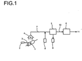
- illustration 1 shows a schematic representation of the entire process. Shown is the cylinder (1) on which a flexographic printing element is mounted. A laser (2) emits a laser beam (3), with which the relief-forming layer is engraved. For clarity, only one laser and only one beam are shown, but it can also be multiple beams of several similar or different types of laser, for example, CO 2 laser or Nd-YAG laser. Via a suction device (4), the degradation products of the layer produced by the laser are sucked off and the mixture of air, aerosols and gaseous degradation products (7) is fed via a line to the filter unit. In the illustration, for better clarity, omitted suction units such as fans, vacuum pumps or the like, which are required for suction and transport of the exhaust gas. Depending on the pressure loss of the entire device, a single suction unit may be sufficient, or it must be installed at different points of the system several Ansaugaggregate.
- a single suction unit may be sufficient, or it must be installed at different points of the system several Ansaugaggregat
Abstract
Description
Die vorliegende Erfindung betrifft ein Verfahren Herstellung von Flexodruckplatten mittels Laser-Direktgravur, bei dem man die im Zuge der Gravur gebildeten partikulären und gasförmigen Abbauprodukte mittels einer Absaugvorrichtung aufnimmt und den mit den Abbauprodukten beladenen Abgasstrom mittels einer Kombination aus mindestens einem Feststofffilter und mindestens einer oxidativ arbeitenden Reinigungsstufe reinigt.The present invention relates to a method of producing flexographic printing plates by means of direct laser engraving, in which the particulate and gaseous decomposition products formed during the engraving are taken up by means of a suction device and the exhaust gas stream laden with the degradation products by means of a combination of at least one solid filter and at least one oxidatively operating Cleaning stage cleans.
Bei der Laser-Direktgravur zur Herstellung von Flexodruckformen wird ein druckendes Relief mit einem Laser direkt in die reliefbildende Schicht eines Flexodruckelementes eingraviert. Ein nachfolgender Entwicklungsschritt wie beim konventionellen Verfahren zur Herstellung von Flexodruckformen ist nicht mehr erforderlich. Die Herstellung von Flexodruckformen mittels Laser-Direktgravur ist prinzipiell bekannt, beispielsweise aus
Bei der Laser-Direktgravur absorbiert die Reliefschicht Laserstrahlung in einem solchen Ausmaße, so dass sie an solchen Stellen, an denen sie einem Laserstrahl ausreichender Intensität ausgesetzt ist, entfernt oder zumindest abgelöst wird. Die Schicht bzw. deren Bestandteile werden dabei verdampft und/oder zersetzt, so dass ihre Zersetzungsprodukte in Form von heißen Gasen, Dämpfen, Rauch, Aerosolen oder kleinen Partikeln von der Schicht entfernt werden. Gebräuchlich zur Gravur sind insbesondere leistungsstarke IR-Laser wie beispielsweise CO2-Laser oder Nd-YAG-Laser. Geeignete Apparaturen zur Gravur von Flexodruckformen sind beispielsweise in
Typische Reliefschichtdicken von Flexodruckformen liegen üblicherweise zwischen 0,5 und 7 mm. Die nichtdruckenden Vertiefungen im Relief betragen im Rasterbereich mindestens 0,03 mm, bei anderen Negativelementen deutlich mehr und können bei dicken Platten Werte von bis zu 3 mm annehmen. Bei der Laser-Direktgravur müssen mit dem Laser also große Mengen an Material entfernt werden. Schon bei einer Gravurtiefe von nur 0,5 bis 0,7 mm und durchschnittlich 70 % Abtragungsgrad werden ca. 500 g Material pro m2 Platte abgetragen. Die Laser-Direktgravur unterscheidet sich in diesem Punkt sehr deutlich von anderen Techniken aus dem Bereich der Druckplatten, bei denen Laser nur zum Beschreiben einer Maske eingesetzt werden, aber die eigentliche Herstellung der Druckform nach wie vor mittels eines Auswasch- bzw. Entwicklungsprozesses erfolgt. Derartige laserbeschreibbare Masken haben üblicherweise nur eine Dicke von wenigen µm. Die Mengen des zu entfernenden Materials betragen in diesem Falle daher üblicherweise nur 2 bis 6 g / m2.Typical relief layer thicknesses of flexographic printing plates are usually between 0.5 and 7 mm. The non-printing depressions in the relief amount to at least 0.03 mm in the grid area, significantly more in the case of other negative elements and can assume values of up to 3 mm for thick plates. In laser direct engraving, therefore, the laser must be removed large amounts of material. Already at an engraving depth of only 0.5 to 0.7 mm and an average of 70% degree of ablation about 500 g of material per m 2 plate are removed. Laser direct engraving differs very clearly in this respect from other techniques in the field of printing plates, in which lasers are used only for writing a mask, but the actual production of the printing form still takes place by means of a washout or development process. Such laser-writable masks usually have only a thickness of a few microns. The amounts of material to be removed in this case therefore usually only 2 to 6 g / m 2 .
Unter dem Einfluss der Laserstrahlung wird das Material der reliefbildenden Schicht zum einen verdampft, andererseits in mehr oder weniger große Bruchstücke gespalten. Hierbei entstehen einerseits klebrige organische Aerosole mit einem Partikeldurchmesser von üblicherweise < 1 µm und außerdem flüchtige organische Substanzen. Bei den flüchtigen Komponenten kann es sich sowohl um verschiedene Pyrolyse-Produkte handeln, wie auch um definierte Monomere, die durch thermische Depolymerisation polymerer Komponenten erzeugt werden. Moderne Flexodruckplatten enthalten üblicherweise Bindemittel, welche als monomere Bausteine Styrol sowie Butadien und/oder Isopren enthalten. Es kann sich beispielsweise um Blockcopolymere vom Styrol-Butadien- oder vom Styrol-Isopren-Typ handeln. Auch weitere Komponenten von Flexodruckplatten, wie z.B. Weichmacheröle können Butadien oder Isopren als Bausteine enthalten. Durch Depolymerisation von Bindemitteln und Weichmachern entstehen bei der Gravur von Flexodruckplatten auf Basis von SIS- oder SBS-Kautschuken neben anderen Abbauprodukten große Mengen an Styrol und Isopren bzw. Butadien. Weitere Einzelheiten zu den entstehenden Zersetzungsprodukten und dem Umgang damit sind beispielsweise offenbart in Martin Goede, "Entstehung und Minderung der Schadstoffemissionen bei der Laserstrahlbearbeitung von Polymenwerkstoffen" Fortschritt-Berichte VDI, Reihe 5, Nr. 587, Düsseldorf, VDI-Verlag, 2000.Under the influence of the laser radiation, the material of the relief-forming layer is evaporated on the one hand, on the other hand split into more or less large fragments. On the one hand sticky organic aerosols with a particle diameter of usually <1 μm and also volatile organic substances are formed. The volatile components can be both different pyrolysis products as well as defined monomers produced by thermal depolymerization of polymeric components. Modern flexographic printing plates usually contain binders which contain as monomeric building blocks styrene and also butadiene and / or isoprene. For example, they may be styrene-butadiene or styrene-isoprene block copolymers. Other components of flexographic printing plates, such as plasticizer oils may contain butadiene or isoprene as building blocks. By depolymerizing binders and plasticizers, engraving of flexographic printing plates based on SIS or SBS rubbers produces, in addition to other degradation products, large amounts of styrene and isoprene or butadiene. Further details on the resulting decomposition products and how they are handled are disclosed, for example, in Martin Goede, "Origin and Reduction of Pollutant Emissions in Laser Beam Processing of Polymeric Materials" Progress Reports VDI,
Laserapparaturen zum Schneiden oder Gravieren weisen üblicherweise Absaugvorrichtungen auf, mit denen die gebildeten Abbauprodukte aufgenommen werden. Beispiele für Laserköpfe mit integrierter Absaugung sind in
Bei der Lasergravur von Flexodruckplatten entsteht ein Abgasstrom, weicher neben der angesaugten Luft große Mengen an gasförmigen Produkten, insbesondere Styrol, Butadien und/oder Isopren, sowie große Mengen an klebrigen Aerosolen enthält. Die Abbauprodukte können nicht einfach an die Umwelt abgegeben werden, sondern die Abgase müssen gereinigt werden, um die zulässigen Grenzwerte einzuhalten. Beispielsweise darf nach der deutschen Technischen Anleitung Luft das Abgas nicht mehr als 1 mg Butadien pro m3 enthalten.In the laser engraving of flexographic printing plates creates an exhaust gas stream, in addition to the sucked air contains large amounts of gaseous products, in particular styrene, butadiene and / or isoprene, and large amounts of sticky aerosols. The degradation products can not simply be released to the environment, but the exhaust gases must be cleaned to comply with the permitted limits. For example, according to the German Technical Instructions on Air, the exhaust gas may not contain more than 1 mg of butadiene per m 3 .
In "
Dieses Verfahren zur Abgasreinigung weist jedoch bei der Anwendung im Bereich der Laser-Direktgravur von Flexodruckplatten eine nicht ausreichende Wirtschaftlichkeit auf. Butadien und Isopren werden an Aktivkohle nur sehr schlecht absorbiert. Die maximale Beladung von Butadien an Aktivkohle beträgt bei Raumtemperatur nur ca. 4 Gew. %. Die Kapazität einer Füllung ist daher schon sehr schnell erschöpft.However, this method of exhaust gas purification, when used in the field of laser direct engraving of flexographic printing plates on an insufficient efficiency. Butadiene and isoprene are absorbed only very badly on activated carbon. The maximum loading of butadiene on activated carbon is only about 4% by weight at room temperature. The capacity of a filling is therefore very quickly exhausted.
Weiterhin muss bei der Lasergravur von Flexodruckplatten sehr intensiv abgesaugt werden, um zu verhindern, dass sich die im Zuge der Gravur gebildeten, sehr klebrigen Aerosole wieder auf der druckenden Oberfläche der Platte abscheiden. Die Wiederabscheidung von Aerosolen auf der Oberfläche ist höchst unerwünscht, da sich durch die Abscheidungen beim Drucken das Druckbild erheblich verschlechtert. Die Oberfläche der Druckform muss daher für den Fall, dass sich Polymere wieder abscheiden, nach der Gravur mit einem geeigneten Reinigungsmittel, beispielsweise mit einem üblichen Flexoauswaschmittel nachgereinigt werden. Da die Druckformen im Flexoauswaschmittel quellen, muss die Druckform vor dem Einsatz wieder sorgfältig getrocknet werden. Dies dauert üblicherweise 2 bis 3 Stunden und ist höchst unerwünscht, da hierdurch der Zeitvorteil gegenüber konventioneller Verarbeitung wieder zunichte gemacht wird.Furthermore, in the case of laser engraving of flexographic printing plates, it must be extracted very intensively in order to prevent the very sticky aerosols formed during the engraving from being deposited again on the printing surface of the plate. The re-deposition of aerosols on the surface is highly undesirable, since the printed image deteriorates considerably as a result of the depositions during printing. The surface of the printing forme must therefore be cleaned in the event that reposition polymers again after engraving with a suitable cleaning agent, for example with a conventional flexo wash. Since the printing plates swell in the flexo wash-off agent, the printing form must be carefully dried again before use. This usually takes 2 to 3 hours and is highly undesirable, as this time advantage over conventional processing is nullified.
Um das Wiederabscheiden zu vermeiden, sind zum Absaugen typischerweise mindestens 0,5 m3 Luft pro g der Zersetzungsprodukte erforderlich. Das Abgas bei der Laser-Direktgravur von Flexodruckplatten ist daher durch sehr hohe Volumenströme bei geringer Beladung gekennzeichnet. Die gasförmigen Produkte sind nur in geringer Konzentration im Gasstrom enthalten und das Adsorptions-Desorptions-Gleichgewicht an Aktivkohle ist ungünstig für eine vollständige Abscheidung von Butadien. Daher sind sehr große Aktivkohlefilter erforderlich und die Kosten zur Entsorgung und/oder Reaktivierung der Aktivkohle dementsprechend sehr hoch. Zeolithe adsorbieren Butadien und Isopren zwar besser als Aktivkohle, sind aber auch deutlich teurer als Aktivkohle. Außerdem fallen nach wie vor Kosten zur Reaktivierung und/oder Entsorgung an.To avoid redeposition, typically at least 0.5 m 3 of air per gram of decomposition products are required for aspiration. The exhaust gas in the direct laser engraving of flexographic printing plates is therefore characterized by very high volume flows at low load. The gaseous products are only present in low concentration in the gas stream and the adsorption-desorption equilibrium of activated carbon is unfavorable for complete deposition of butadiene. Therefore, very large activated carbon filters are required and the costs for disposal and / or reactivation of the activated carbon accordingly very high. Although zeolites adsorb butadiene and isoprene better than activated carbon, they are also considerably more expensive than activated carbon. In addition, there are still costs for reactivation and / or disposal.
Weiterhin ist zu berücksichtigen, dass es sich bei Anlagen zur Laser-Direktgravur von Flexodruckplatten nicht um Großanlagen in industriellem Maßstab handelt. Die Gravur von Druckplatten findet vielmehr endverbrauchemah und dezentral entweder in einer Druckerei oder in einer Klischeeanstalt statt, also in typischen Kleinbetrieben oder mittelständischen Betrieben statt. Die Anlagen werden nicht vollkontinuierlich sondern chargenweise betrieben. Eine Abgasreinigungsanlage für die Laser-Direktgravur von Flexodruckplatten muss auch diese Randbedingungen berücksichtigen.Furthermore, it has to be taken into consideration that systems for laser direct engraving of flexographic printing plates are not large-scale plants on an industrial scale. The engraving of printing plates rather takes place endverbrauchemah and decentralized either in a printing or in a cliché instead of, ie in typical small businesses or medium-sized businesses instead. The plants are not operated fully continuous but batchwise. An emission control system for laser direct engraving of flexographic printing plates must also take these boundary conditions into consideration.
Dementsprechend wurde ein Verfahren zur Herstellung von Flexodruckformen mittels Laser-Direktgravur durch Eingravieren eines Reliefs in ein lasergravierbares Flexodruckelement unter Verwendung einer Laserapparatur gefunden, welche mindestens
- eine Einheit zur Aufnahme eines zylindrischen Trägers für Flexodruckelemente, in der der zylindrische Träger drehbar gelagert werden kann,
- eine Antriebseinheit zum Drehen des Zylinders,
- einen Laserkopf, welcher mindestens einen Laserstrahl emittiert, wobei der Laserkopf sowie die Aufnahmeeinheit mit dem zylindrischen Träger koaxial gegeneinander verschiebbar gelagert sind, sowie
- eine Absaugvorrichtung umfasst,
- (a) Aufbringen eines lasergravierbaren Flexodruckelementes auf den zylindrischen Träger und Montieren des zylindrischen Trägers in die Aufnahmeeinheit,
- (b) Versetzen des zylindrischen Trägers in Drehung,
- (c) Eingravieren eines Druckreliefs in die reliefbildende Schicht mit Hilfe des mindestens einen Laserstrahles, wobei die Tiefe der mit dem Laser einzugravierenden Reliefelemente mindestens 0,03 mm beträgt,
- a unit for receiving a cylindrical support for flexographic printing elements, in which the cylindrical support can be rotatably mounted,
- a drive unit for rotating the cylinder,
- a laser head, which emits at least one laser beam, wherein the laser head and the receiving unit with the cylindrical support are mounted coaxially against each other displaceable, and
- comprises a suction device,
- (a) applying a laser-engravable flexographic printing element to the cylindrical support and mounting the cylindrical support in the receiving unit,
- (b) rotating the cylindrical support,
- (c) engraving a printing relief into the relief-forming layer with the aid of the at least one laser beam, wherein the depth of the relief elements to be engraved with the laser is at least 0.03 mm,
- Abbildung 1:Illustration 1:
- Schematische Darstellung des Verfahrens mit Absaugung (4), Feststofffilter (5) und oxidativer Reinigungsstufe (6)Schematic representation of the process with suction (4), solid filter (5) and oxidative cleaning stage (6)
- Abbildung 2:Figure 2:
- Schematische Darstellung des Feststofffilters (5)Schematic representation of the solids filter (5)
- Abbildung 3:Figure 3:
- Schematische Darstellung der oxidativen Reinigungsstufe (6)Schematic representation of the oxidative purification stage (6)
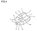
- Abbildung 4:Figure 4:
- Schematische Darstellung einer bevorzugten Ausführungsform der AbsaugungSchematic representation of a preferred embodiment of the suction
- Abbildung 5:Figure 5:
- Schnitt durch eine bevorzugte Ausführungsform der AbsaugungSection through a preferred embodiment of the suction
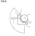
- Abbildung 6:Figure 6:
- Schnitt durch eine andere bevorzugte Ausführungsform der AbsaugungSection through another preferred embodiment of the suction
Als Ausgangsmaterial zur Ausführung des erfindungsgemäßen Verfahrens wird ein lasergravierbares Flexodruckelement eingesetzt, welches in prinzipiell bekannter Art und Weise mindestens einen dimensionsstabilen Träger sowie eine elastomere, reliefbildende Schicht mit einer Dicke von mindestens 0,2 mm, bevorzugt mindestens 0,3 mm und besonders bevorzugt mindestens 0,5 mm umfasst. Im Regelfalle beträgt die Dicke 0,5 bis 2,5 mm.The starting material for carrying out the process according to the invention is a laser-engravable flexographic printing element which, in a manner known in principle, comprises at least one dimensionally stable support and an elastomeric, relief-forming layer having a thickness of at least 0.2 mm, preferably at least 0.3 mm and more preferably at least 0.5 mm. As a rule, the thickness is 0.5 to 2.5 mm.
Bei dem dimensionsstabilen Träger kann es sich in prinzipiell bekannter Art und Weise um eine Polymer- oder Metallfolie handeln, oder aber auch um eine zylindrische Hülse. Die reliefbildende Schicht umfasst mindestens ein elastomeres Bindemittel. Beispiele geeigneter elastomerer Bindemittel umfassen Naturkautschuk, Polybutadien, Polyisopren, Styrol-Butadien-Kautschuk, Nitril-Butadien-Kautschuk, Butyl-Kautschuk, Styrol-Isopren-Kautschuk, Polynorbornen-Kautschuk oder Ethylen-Propylen-Dien-Kautschuk (EPDM) oder thermoplastisch elastomere Blockcopolymere vom Styrol-Butadien oder Styrol-Isopren-Typ. Die reliefbildende Schicht wird üblicherweise durch Vernetzung einer vernetzbaren Schicht erhalten, welche mindestens die besagten Bindemittel sowie zur Vernetzung geeignete Komponenten, beispielsweise ethylenisch ungesättigte Monomere sowie geeignete Initiatoren umfasst. Die Vernetzung kann beispielsweise fotochemisch vorgenommen werden. Weiterhin können optional Absorber für Laserstrahlung, Weichmacher und andere Hilfsstoffe wie Farbstoffe, Dispergierhilfsmittel oder dergleichen eingesetzt werden. Lasergravierbare Flexodruckelemente sind prinzipiell bekannt. Lasergravierbare Flexodruckelemente können nur eine reliefbildende Schicht oder auch mehrere gleichen, ähnlichen oder verschiedenen Aufbaues umfassen. Einzelheiten zum Aufbau und zur Zusammensetzung lasergravierbarer Flexodruckelemente sind beispielsweise in
Das erfindungsgemäße Verfahren ist nicht auf die Verwendung ganz bestimmter Flexodruckelemente als Ausgangsmaterialien beschränkt. Die Vorteile des Verfahrens kommen aber ganz besonders bei solchen Flexodruckelementen zum Tragen, deren reliefbildende Schicht Butadien und /oder Isopren-Einheiten als Bausteine umfassende Komponenten umfasst. Zu nennen sind hier insbesondere Bindemittel, welche Butadien und/oder Isopren-Einheiten umfassen, wie beispielsweise Naturkautschuk, Polybutadien, Polyisopren, Styrol-Butadien-Kautschuk, Nitril-Butadien-Kautschuk, Styrol-Isopren-Kautschuk, oder thermoplastisch elastomere Blockcopolymere vom Styrol-Butadien oder Styrol-Isopren-Typ, wie beispielsweise SBS- oder SIS-Blockcopolymere. Zu nennen sind weiterhin Butadien oder Isopren umfassende Weichmacher wie beispielsweise oligomere Styrol-Butadien-Copolymere, flüssige Oligobutadiene oder Oligoisoprene, insbesondere solche mit einem Molekulargewicht zwischen 500 und 5000 g/mol oder flüssige oligomere Acrylnitril-Butadien-Copolymere. Bei der Laser-Direktgravur derartiger Flexodruckelemente entsteht ein Abgas mit einem besonders hohen Gehalt von Butadien und/oder Isopren, welches sich mittels des erfinderischen Verfahrens dennoch zuverlässig und ökonomisch reinigen lässt.The inventive method is not limited to the use of very specific flexographic printing elements as starting materials. However, the advantages of the process are particularly noticeable in flexographic printing elements whose relief-forming layer comprises butadiene and / or isoprene units as components comprising components. Particularly noteworthy here are binders which comprise butadiene and / or isoprene units, for example natural rubber, polybutadiene, polyisoprene, styrene-butadiene rubber, nitrile-butadiene rubber, styrene-isoprene rubber or thermoplastic elastomeric block copolymers of styrene Butadiene or styrene-isoprene type such as SBS or SIS block copolymers. Also to be mentioned are butadiene or isoprene comprising plasticizers such as oligomeric styrene-butadiene copolymers, liquid oligobutadienes or oligoisoprenes, in particular those having a molecular weight between 500 and 5000 g / mol or liquid oligomeric acrylonitrile-butadiene copolymers. The direct laser engraving of such flexographic printing elements produces an exhaust gas with a particularly high content of butadiene and / or isoprene, which nevertheless can be cleaned reliably and economically by means of the inventive method.
Bei der zur Ausführung des erfindungsgemäßen Verfahrens eingesetzten Laserapparatur handelt es sich um eine Apparatur mit einem sogenannten "rotierenden Zylinder". Die Apparatur weist in prinzipiell bekannter Art und Weise eine Einheit zur Aufnahme eines zylindrischen Trägers für Flexodruckelemente auf, so dass ein zylindrischer Träger drehbar gelagert werden kann. Die Aufnahmeeinheit ist mit einer Antriebseinheit verbunden, durch die der Zylinder in Drehung versetzt werden kann. Um einen ruhigen Lauf zu gewährleisten, sollte der zylindrische Träger üblicherweise an beiden Seiten unterstützt werden. Derartige Apparaturen sind prinzipiell bekannt. Ihr Aufbau und ihre Funktionsweise ist beispielsweise dargestellt in
Bei dem zylindrischen Träger kann es sich beispielsweise um eine Trägerwalze aus Metall oder anderen Materialien handeln, auf die ein übliches flächenförmiges Flexodruckelement auf flexiblem Träger mittels eines doppelseitigen Klebebandes geklebt wird. Als Flexodruckelemente können aber auch sogenannte Sleeves eingesetzt werden. Bei Sleeves ist eine reliefbildende Schicht direkt oder indirekt auf einen zylindrischen Träger, beispielsweise aus Aluminium oder Kunststoffen aufgebracht. Der Sleeve wird als solcher in die Druckmaschine eingebaut. Im Regelfalle wird der Träger von der reliefbildenden Schicht vollständig umhüllt. Man spricht dann von sogenannten Endlos-Nahtios-Sleeves. Zur Verbesserung der drucktechnischen Eigenschaften kann auch zwischen reliefbildender Schicht -wahlweise mit oder ohne dimensionsstabilem Träger- und der Hülse ein elastischer Unterbau vorhanden sein.By way of example, the cylindrical carrier can be a metal or other carrier roll onto which a conventional flexible flexographic printing element is adhered by means of a double-sided adhesive tape. However, so-called sleeves can also be used as flexographic printing elements. In sleeves, a relief-forming layer is applied directly or indirectly to a cylindrical support, for example of aluminum or plastics. The sleeve is installed as such in the printing press. As a rule, the support is completely enveloped by the relief-forming layer. One speaks then of so-called endless seamios-sleeves. To improve the printing properties, an elastic substructure may also be present between the relief-forming layer-optionally with or without a dimensionally stable carrier and the sleeve.
Sleeves können direkt in die Aufnahmeeinheit montiert werden. Der zylindrische Träger des Sleeves ist in diesem Falle identisch mit dem zylindrischen Träger der Apparatur. Sleeves können auch auf eine Trägerwalze aufgeschoben und fixiert werden. Vorteilhaft kann man für Sleeves sogenannte Luftzylinder einsetzen, bei dem das Auf- und Abschieben der Sleeves auf den Trägerzylinder durch ein Luftkissen aus Druckluft unterstützt wird. Einzelheiten hierzu finden sich beispielsweise in "
Die Apparatur verfügt weiterhin über einen Laserkopf, welcher mindestens einen Laserstrahl emittiert. Bevorzugt werden Köpfe eingesetzt, welche mehrere Laserstrahlen emittieren, beispielsweise 3 Laserstrahlen. Sie können unterschiedliche Leistung aufweisen. Der Laserkopf und der zylindrische Träger sind koaxial gegeneinander verschiebbar gelagert. Beim Betrieb der Apparatur werden der zylindrische Träger in Drehung versetzt und der Laserstrahl und der Zylinder translatorisch gegeneinander verschoben, so dass der Laserstrahl die gesamte Oberfläche des Flexodruckelementes nach und nach abtastet und -abhängig von Steuersignal- durch entsprechende Strahlintensität die Oberfläche mehr oder weniger stark abträgt. Wie die translatorische Bewegung zwischen dem Laserkopf und dem Zylinder zustande kommt, ist nicht erfindungswesentlich. Es können der Zylinder oder der Laserkopf oder auch beide verschiebbar gelagert sein.The apparatus also has a laser head, which emits at least one laser beam. Preferably, heads are used which emit a plurality of laser beams, for example 3 laser beams. They can have different performance. The laser head and the cylindrical carrier are mounted coaxially against each other displaceable. During operation of the apparatus, the cylindrical support in Rotation offset and the laser beam and the cylinder translationally shifted from each other, so that the laser beam gradually scans the entire surface of the flexographic printing element and depending on Steuerignal- by appropriate beam intensity, the surface more or less strongly ablates. How the translational movement between the laser head and the cylinder comes about is not essential to the invention. It may be slidably mounted, the cylinder or the laser head or both.
Die erfindungsgemäß eingesetzte Apparatur verfügt weiterhin über eine Vorrichtung zum Absaugen der im Zuge der Gravur gebildeten Abbauprodukte. Die Absaugung sollte möglichst nahe zu der Stelle angeordnet werden, an der der Laserstrahl auf die Oberfläche der reliefbildenden Schicht trifft. Es kann sich beispielsweise um eine darüber angeordnete Glocke handeln. Die Absaugung kann in der Apparatur fixiert sein oder -für den Fall eines beweglich gelagerten Laserkopfes- bevorzugt mit dem Laserkopf mitbewegt werden. Dem Fachmann sind Konstruktionen von Absaugungen für Laserköpfe prinzipiell bekannt. Beispielhaft sei auf
Vorteilhaft ist die gesamte Apparatur gekapselt, um unerwünschten Austritt der Abbauprodukte in die Umgebung noch besser zu unterbinden. Der Zugang zum Inneren der Apparatur, insbesondere zu Laserkopf und Trägerzylinder, wird über verschließbare Klappen, Türen, Schiebetüren oder dergleichen gewährleistet.Advantageously, the entire apparatus is encapsulated to prevent unwanted leakage of the degradation products in the environment even better. Access to the interior of the apparatus, in particular to the laser head and carrier cylinder, is ensured by means of closable flaps, doors, sliding doors or the like.
Das erfindungsgemäße Verfahren sowie bevorzugte Ausführungsformen sind schematisch mittels der Abbildungen 1 bis 6 dargestellt. Die Abbildungen sollen dem leichteren Verständnis dienen, ohne dass die Erfindung damit auf die dargestellte Ausführungsform beschränkt werden soll.The inventive method and preferred embodiments are shown schematically by means of Figures 1 to 6. The illustrations are intended to facilitate understanding, without the invention being limited to the illustrated embodiment.
Die Menge des angesaugten Gasvolumens pro Zeiteinheit (Abluftvolumenstrom) und des pro Gewichtseinheit abgebauten Materials beträgt mindestens 0,1 m3 pro g abgebauten Materials. Im Regelfalle wird die Oberfläche der Druckform umso weniger durch Abbauprodukte verunreinigt, je höher der Abluftvolumenstrom ist. Bevorzugt beträgt der Volumenstrom mindestens 0,5 m3/g und besonders bevorzugt mindestens 1,0 m3/g. Bei einer Laserapparatur durchschnittlicher Größe, welche zur Gravur von etwa 1 m2 Platte / h und einem Abtrag von 500 bis 1000 g/m2 ausgelegt ist, entspricht dies je nach Abtrag einem Volumenstrom von mindestens 50 bis 100 m3/h, bevorzugt mindestens 250 bis 500 m3/h und besonders bevorzugt mindestens 500 bis 1000 m3/h.The amount of gas volume drawn in per unit time (exhaust air volume flow) and the material degraded per unit weight is at least 0.1 m 3 per g of degraded material. As a rule, the surface of the printing form becomes less contaminated by decomposition products, the higher the exhaust air volume flow is. The volume flow is preferably at least 0.5 m 3 / g and particularly preferably at least 1.0 m 3 / g. In a laser apparatus average size, which is designed for engraving of about 1 m 2 plate / h and a removal of 500 to 1000 g / m 2 , this corresponds depending on the removal of a volume flow of at least 50 to 100 m 3 / h, preferably at least 250 to 500 m 3 / h and more preferably at least 500 to 1000 m 3 / h.
Der Abgasstrom (7) wird zunächst in einem Feststofffilter bzw. Partikelfilter (5) gereinigt. Hierbei werden die im Gasstrom vorhandenen partikulären Abbauprodukte, beispielsweise klebrige Aerosole, abgeschieden, während die gasförmigen Bestandteile des Abgases den Filter passieren. Der Feststofffilter umfasst in prinzipiell bekannter Art und Weise geeignete Filterelemente zum Abscheiden der festen Partikel. Die Abscheidung der partikulären Abbauprodukte wird in Gegenwart eines feinteiligen, nicht-klebrigen Feststoffes vorgenommen. Dadurch wird vermieden, dass die klebrigen Aerosole die Filterelemente verkleben. Der feinteilige Feststoff kann direkt in den Feststofffilter eindosiert werden. Bevorzugt wird er aber noch vor dem Feststofffilter aus einem Vorratsgefäß (8) in die Leitung (7) eingespeist, beispielsweise mit Hilfe eines geeigneten Trägergases, um eine möglichst innige Mischung mit dem Abgas zu erreichen. Der feinteilige, nicht-klebrige Feststoff belegt die klebrigen Aerosole und die Filterelemente. Er verhindert somit, dass der Feststoff die Filter verklebt. Statt dessen resultiert ein gut abscheidbarer Feststoff (9). Als feinteilige, nicht-klebrige Feststoffe kommen insbesondere Feststoffe mit einem Anteil von mindestens 50% an Partikeln der Größe ≤ 20 µm in Frage. Bevorzugt beträgt der Anteil an Partikeln ≤ 2 µm mindestens 50%.The exhaust gas stream (7) is first cleaned in a solids filter or particle filter (5). Here, the present in the gas stream particulate degradation products, such as sticky aerosols, deposited while the gaseous components of the exhaust gas pass through the filter. The solid-state filter comprises, in a manner known in principle, suitable filter elements for separating off the solid particles. The deposition of the particulate degradation products is carried out in the presence of a finely divided, non-sticky solid. This prevents the sticky aerosols from sticking to the filter elements. The finely divided solid can be metered directly into the solids filter. Preferably, however, it is fed into the line (7) from a storage vessel (8) before the solids filter, for example with the aid of a suitable carrier gas in order to achieve intimate mixing with the exhaust gas. The finely divided, non-sticky solid occupies the sticky aerosols and the filter elements. It thus prevents the solid from sticking to the filters. Instead, a well-settable solid (9) results. As finely divided, non-sticky solids are in particular solids with a proportion of at least 50% of particles of size ≤ 20 microns in question. The proportion of particles ≦ 2 μm is preferably at least 50%.
Beispiele geeigneter Feststoffe umfassen Lehm, CaCO3, Aktivkohle, SiO2, organisch modifizierte Kieselsäuren, Zeolithe, feinteilige Pulver von Kaolinit, Muskovit oder Monmorillonit. Die Menge des Feststoffes wird vom Fachmann je nach der Art des Abgases bestimmt. In aller Regel bewährt hat sich eine Menge von 0,1 bis 10 g Feststoff pro g abgetragenen Materials, bevorzugt 0,5 bis 2 g Feststoff pro g abgetragenen Materials.Examples of suitable solids include loam, CaCO 3 , activated carbon, SiO 2 , organically modified silicas, zeolites, finely divided powders of kaolinite, muscovite or monmorillonite. The amount of solid is determined by the person skilled in the art according to the nature of the exhaust gas. As a rule, an amount of 0.1 to 10 g of solid per g of abraded material, preferably 0.5 to 2 g of solid per g of ablated material has proven successful.
Die Bauart des Feststofffilters ist nicht erfindungswesentlich. Eine typische Ausführungsform eines Feststofffilters ist in
Der noch mit den gasförmigen Abbauprodukten beladene Abgasstrom (10) wird in eine zweite Filtereinheit (6) eingeleitet, in der die verbliebenen gasförmigen Abbauprodukte oxidativ abgebaut werden. Es entsteht ein Abgas (11) welches im wesentlichen frei von organischen Stoffen ist. Als Oxidationsmittel kommen vor allem atmosphärischer Sauerstoff und daraus gewonnene Formen von aktivem Sauerstoff, wie beispielsweise atomarer Sauerstoff oder Ozon in Frage.The exhaust gas flow (10), which is still laden with the gaseous degradation products, is introduced into a second filter unit (6), in which the remaining gaseous degradation products are oxidatively decomposed. The result is an exhaust gas (11) which is substantially free of organic matter. As the oxidizing agent are mainly atmospheric oxygen and derived forms of active oxygen, such as atomic oxygen or ozone in question.
Bei der oxidativen Reinigungsstufe handelt es sich um eine Vorrichtung zur katalytischen Oxidation der Abgase. Hierbei werden die im Abgas vorhandenen gasförmigen Abbauprodukte in Gegenwart eines geeigneten Katalysators im wesentlichen zu CO2 und H2O oxidiert. Als Katalysatoren kommen beispielsweise Edelmetallkatalysatoren auf geeigneten Trägern oder Katalysatoren auf Basis von Übergangmetalloxiden oder anderen Übergangsmetallverbindungen, beispielsweise von V, Cr, Mo, W, Co oder Cu in Frage. Der Fachmann trifft unter den möglichen Katalysatoren je nach den konkreten Verhältnissen eine geeignete Auswahl. Die Auswahl eines Katalysators richtet sich auch nach dem zu gravierenden Material. Edelmetallkatalysatoren sind im Regelfalle aktiver als Katalysatoren auf Basis von Übergangmetallen, aber empfindlicher gegenüber Katalysatorgiften, wie H2S oder anderen schwefelhaltigen Verbindungen. Zur Gravur von Flexodruckelementen, welche S-haltige Verbindungen enthalten können, z.B. S-Vemetzer, empfiehlt es sich daher, Katalysatoren auf Basis von Übergangsmetalloxiden einzusetzen. Die katalytische Reinigungsstufe wird üblicherweise bei Temperaturen zwischen 250 und 400°C betrieben. Weitere Einzelheiten zur katalytischen Oxidation und dazu geeigneten Katalysatoren sind
Erfindungsgemäß umfasst die zweite Filtereinheit (6) noch eine der oxidativen Reinigungsstufe (15) vorgeschaltete Puffereinheit. Dies ist schematisch in
(13, 14) werden die gasförmigen Anteile im Abgas ganz oder teilweise gesammelt und von dort aus nach und nach wieder in einer definierten Konzentration an die oxidative Reinigungsstufe abgegeben. Vorteilhaft wird hierdurch erreicht, dass Spitzenkonzentrationen der gasförmigen Abbauprodukte im Abgas abgefangen werden können, so dass die Filtereinheit nicht für den Spitzenbetrieb ausgelegt werden muss, sondern mehr oder weniger kontinuierlich arbeiten kann, beispielsweise auch dann, wenn gerade wegen Plattenwechsels nicht graviert wird.According to the invention, the second filter unit (6) also comprises a buffer unit upstream of the oxidative purification stage (15). This is schematically in
(13, 14), the gaseous fractions in the exhaust gas are completely or partially collected and released from there gradually to the oxidative purification stage in a defined concentration. Advantageously, this achieves that peak concentrations of the gaseous degradation products in the exhaust gas can be intercepted, so that the filter unit does not have to be designed for peak operation, but can work more or less continuously, for example, even if it is not engraved just because plate change.
Die Puffereinheit kann beispielsweise aus zwei Gefäßen (13, 14) bestehen, welche mit einem geeigneten Material zum Absorbieren gefüllt sind. Bei geeigneten Materialien handelt es sich beispielsweise um Zeolithe, insbesondere hydrophobe Zeolithe mit 5 bis 6 Å Porengröße. Die Puffer können beispielsweise so betrieben werden, dass zunächst die Abbauprodukte in einem Absorber gesammelt werden, bis dieser seine maximale Beladung erreicht hat. Dann wird auf den zweiten Absorber umgeschaltet, während der erste wieder geleert wird, beispielsweise durch Temperaturerhöhung und/oder Durchleiten von Gasen, und die adsorbierten organischen Stoffe nach und nach an die oxidative Reinigungsstufe (15) abgibt. Es sind selbstverständlich auch andere Ausführungsformen einer Puffereinheit denkbar. Beispielsweise könnte das Abgas im Regelfalle direkt in die oxidative Reinigungsstufe geleitet und nur bei Überschreiten einer bestimmten Fracht organischer Verunreinigungen ein Teil des Abgasstromes in den Puffer umgeleitet werden, um eine Überlastung der oxidativen Reinigungsstufe zu vermeiden. Bei geringerer Beladung kann der Inhalt des Puffers dann wieder in den Abgasstrom entleert werden.The buffer unit may for example consist of two vessels (13, 14) which are filled with a suitable material for absorbing. Suitable materials are, for example, zeolites, in particular hydrophobic zeolites with 5 to 6 Å pore size. The buffers can be operated, for example, so that first the degradation products are collected in an absorber until this has reached its maximum load. Then, the second absorber is switched, while the first is emptied again, for example by increasing the temperature and / or passing gases, and the adsorbed organic substances gradually to the oxidative cleaning stage (15) releases. Of course, other embodiments of a buffer unit are conceivable. For example, the exhaust gas could normally be passed directly into the oxidative purification stage and only when a certain amount of organic contaminants is exceeded, part of the exhaust gas flow can be diverted into the buffer in order to avoid overloading the oxidative purification stage. At lower load, the contents of the buffer can then be emptied back into the exhaust stream.
Das erfindungsgemäße Verfahren kann selbstverständlich noch weitere Verfahrensschritte und die eingesetzte Apparatur noch weitere Komponenten umfassen. Beispielsweise kann es sich hierbei um eine zusätzliche Filtereinheit handeln, in welcher gezielt H2S oder andere S-haltige Verbindungen abgeschieden werden. Hierbei kann es sich beispielsweise um eine absorptive Filterstufe (z.B. eine Alkaliwäsche) oder um Biofilter handeln.Of course, the process according to the invention may also comprise further process steps and the apparatus used may comprise further components. For example, this may be an additional filter unit in which H 2 S or other S-containing compounds are selectively precipitated. This may be, for example, an absorptive filter stage (eg, an alkali wash) or biofilter.
Es kann nur eine einzige Einheit zur Laser-Direktgravur mit der beschriebenen Kombination aus zwei Filtereinheiten verbunden sein. Falls ein Betrieb aber mehrere Laserapparaturen betreibt, können durchaus auch mehrere Laserapparaturen auf geeignete Art und Weise mit einer einzigen Kombination aus Filtereinheiten zur gemeinsamen Reinigung der Abgase aller Laserapparaturen verbunden sein.Only a single direct laser engraving unit may be associated with the described combination of two filter units. However, if an operation operates several laser apparatuses, several laser apparatuses may well be connected in a suitable manner to a single combination of filter units for jointly cleaning the exhaust gases of all laser apparatuses.
In einer besonders vorteilhaften Ausführungsform des erfindungsgemäßen Verfahrens wird eine spezielle Absaugvorrichtung eingesetzt, wie in den Abbildungen 4 bis 6 schematisch dargestellt. Hierdurch wird eine besonders vollständige und schnelle Absaugung der Zersetzungsprodukte gewährleistet und die Verunreinigung der Oberfläche der gravierten Flexodruckformen durch Zersetzungsprodukte im wesentlichen verhindert.In a particularly advantageous embodiment of the method according to the invention, a special suction device is used, as shown schematically in Figures 4 to 6. This ensures a particularly complete and rapid extraction of the decomposition products and substantially prevents the contamination of the surface of the engraved flexographic printing plates by decomposition products.
Die Absaugvorrichtung (4) ist mit dem Laserkopf (Der Laserkopf ist in
Die Absaugvorrichtung (4) weist mindestens eine Durchführung (18) zum Anschluss einer Absaugleitung (19) auf. Die Durchführung (18) befindet sich bevorzugt an der Rückseite (16) oder der Unterseite der Vorrichtung, ohne dass die Erfindung darauf beschränkt sein soll. Es kann sich auch um mehrere Durchführungen für das Abgas handeln. Die Rückseite weist weiterhin mindestens ein Fenster (20) zur Durchführung eines Laserstrahles (3) auf. Sie kann selbstverständlich auch mehr als ein Fenster aufweisen, falls mehrere Laserstrahlen zum Einsatz kommen. In
Die Absaugöffnung (17) weist zwei gegenüber liegende-im Regelfalle horizontal verlaufende- bogenförmige Kanten (21) und (21 a) auf, deren Radius dem Radius des Trägerzylinders angepasst ist. Die Länge der Kanten (21) und (21 a) ist bevorzugt gleich.
Bei den bogenförmigen Kanten handelt es sich bevorzugt um kreisförmige Kanten. In diesem Falle ist der Abstand Δ entlang der gesamten Kante gleich. Es kann sich aber auch um eine elliptisch oder anderes bogenförmig geformte Kante handeln. In diesem Falle verändert sich der Abstand Δ entlang der Kante. Bevorzugt sollte aber auch in diesem Falle Δ an jeder Stelle der Kante kleiner als 20 mm sein. Ein veränderlicher Abstand Δ kann sich auch dann ergeben, wenn der Trägerzylinder gegen einen anderen Trägerzylinder mit geringerem Radius ausgetauscht wird. Dies sollte aber möglichst vermieden werden, sondern für Trägerzylinder verschiedenen Durchmessers sollten auch jeweils angepasste Absaugungen vorrätig sein.The arcuate edges are preferably circular edges. In this case, the distance Δ along the entire edge is the same. But it may also be an elliptical or other arcuate shaped edge. In this case, the distance Δ varies along the edge. In this case, however, Δ should preferably be smaller than 20 mm at any point of the edge. A variable distance Δ can also arise when the carrier cylinder is replaced by another carrier cylinder with a smaller radius. However, this should be avoided as far as possible, but for carrier cylinders of different diameters, customized exhaust systems should also be available in each case.
Die Enden der bogenförmigen Kanten weisen jeweils den Winkel α zueinander auf. Durch diesen Winkel wird die Größe der Absaugöffnung definiert. α kann eine Größe von bis zu 180° aufweisen. Bewährt hat sich ein Winkel α von 30° bis 180°. Die Enden der Kanten (21) und (21 a) sind jeweils durch die einander gegenüber liegenden Kanten (22) und (22a) miteinander verbunden. Auch diese Kanten befinden sich bevorzugt jeweils im Abstand Δ von der Oberfläche des lasergravierbaren Flexodruckelementes. Bei den verbindenden Kanten kann es sich um gerade Kanten handeln (in
Alle Kanten sollten bevorzugt abgerundet sein, um unnötige Turbulenzen zu vermeiden. Zusätzlich kann um die Kanten (21), (21 a), (22) und/oder (22a) eine Konstruktion angebracht sein, die zur Vergößerung des Abluft-Erfassungsquerschnittes dient. Geeignete Konstruktionen sind beispielsweise plane oder gekrümmte Bleche, die kragen-oder flanschähnlich um den eigentlichen Absaugkopf herum angeordnet sind.All edges should preferably be rounded to avoid unnecessary turbulence. In addition, around the edges (21), (21 a), (22) and / or (22 a) be mounted a construction which serves to enlarge the exhaust air detection cross-section. Suitable constructions are, for example, flat or curved sheets which are arranged collar-like or flange-like around the actual suction head.
Optional kann die Absaugvorrichtung noch weitere Durchführungen aufweisen, beispielsweise zur Durchführung von analytischen Instrumenten, Messköpfen oder dergleichen, bzw. deren Anschlüsse.Optionally, the suction device may have further bushings, for example for the performance of analytical instruments, measuring heads or the like, or their connections.
Zweckmäßigerweise ist die Absaugvorrichtung leicht demontierbar mit dem Laserkopf verbunden, beispielsweise durch Schnellspannschrauben. Hierdurch wird erreicht, dass beim Auswechseln des zylindrischen Trägers gegen einen mit einem anderen Radius auch ohne großen Zeitverlust eine neue Absaugevorrichtung mit entsprechend angepasstem Radius montiert werden kann.Appropriately, the suction device is easily removable connected to the laser head, for example by quick-release screws. This ensures that when replacing the cylindrical support against a with a different radius, even without much loss of time a new suction with a correspondingly adapted radius can be mounted.
Zur Ausführung des erfindungsgemäßen Verfahrens wird zunächst ein lasergravierbares Flexodruckelementes auf den zylindrischen Träger aufgebracht und der zylindrische Träger in die Aufnahmeeinheit montiert. Zur Montage werden der Laserkopf und der zylindrische Träger soweit auseinandergefahren, dass eine problemlose Montage möglich ist. Auf die Reihenfolge kommt es hierbei nicht an. Falls es sich um ein flächenförmiges Flexodruckelement handelt, kann zunächst der zylindrische Träger in die Apparatur eingebaut werden und dann die Platte darauf. Alternativ können zunächst der Zylinder und das Flexodruckelement außerhalb der Apparatur vormontiert werden und dann in die Apparatur eingebaut werden. Beim Gravieren mehrerer verschiedener Flexodruckelemente nacheinander kann man selbstverständlich den Trägerzylinder in der Aufnahmevorrichtung belassen und die Montage des Flexodruckelementes auf dem bereits in die Aufnahmevorrichtung eingebauten Zylinder vornehmen. Das gleiche gilt, wenn man einen Sleeve in Kombination mit einem Trägerzylinder, beispielsweise einem Luftzylinder, benutzt. Wird der Sleeve selbsttragend, d.h. ohne zusätzlichen Zylinder eingesetzt, ist die Reliefschicht naturgemäß schon auf dem zylindrischen Träger aufgebracht. Nach der Montage wird der mit dem Flexodruckelement versehene zylindrische Träger mittels der Antriebseinheit in Drehung versetzt.To carry out the method according to the invention, a laser-engravable flexographic printing element is first applied to the cylindrical carrier and the cylindrical carrier is mounted in the receiving unit. For mounting the laser head and the cylindrical support are moved apart so far that a trouble-free installation is possible. The order does not matter here. If it is a sheet-like flexographic printing element, first the cylindrical support can be installed in the apparatus and then the plate on it. Alternatively, first the cylinder and the flexographic printing element may be preassembled outside the apparatus and then installed in the apparatus. When engraving several different flexographic printing elements successively one can of course leave the carrier cylinder in the receiving device and make the assembly of the flexographic printing element on the already built into the receiving device cylinder. The same applies if one uses a sleeve in combination with a carrier cylinder, such as an air cylinder. If the sleeve self-supporting, ie used without additional cylinder, the relief layer is naturally already on the cylindrical support applied. After assembly, the cylindrical support provided with the flexographic printing element is rotated by means of the drive unit.
Mit Hilfe des mindestens einen Laserstrahls wird anschließend ein Druckrelief in die reliefbildende Schicht eingraviert. Die Tiefe der einzugravierenden Elemente richtet sich nach der Gesamtdicke des Reliefs und der Art der einzugravierenden Elemente und wird vom Fachmann je nach den gewünschten Eigenschaften der Druckform bestimmt. Die Tiefe der einzugravierenden Reliefelemente beträgt zumindest 0,03 mm, bevorzugt mindestens 0,05 mm ― genannt ist hier die Mindesttiefe zwischen einzelnen Rasterpunkten. Druckplatten mit zu geringen Relieftiefen sind für das Drucken mittels Flexodrucktechnik im Regelfalle ungeeignet, weil die Negativelemente mit Druckfarbe vollaufen. Einzelne Negativpunkte sollten üblicherweise größere Tiefen aufweisen; für solche von 0,2 mm Durchmesser ist üblicherweise eine Tiefe von mindestens 0,07 bis 0,08 mm empfehlenswert. Bei weggravierten Flächen empfiehlt sich eine Tiefe von mehr als 0,15 mm, bevorzugt mehr als 0,3 mm und besonders bevorzugt mehr als 0,5 mm. Letzteres ist natürlich nur bei einem entsprechend dickem Relief möglich.With the help of the at least one laser beam, a printing relief is then engraved in the relief-forming layer. The depth of the elements to be engraved depends on the total thickness of the relief and the type of elements to be engraved and is determined by the person skilled in the art according to the desired properties of the printing form. The depth of the engraved relief elements is at least 0.03 mm, preferably at least 0.05 mm - is called here the minimum depth between individual halftone dots. Printing plates with too low relief depths are generally unsuitable for printing by means of flexographic printing technology because the negative elements are filled with printing ink. Individual negative points should usually have greater depths; for those of 0.2 mm diameter, a depth of at least 0.07 to 0.08 mm is usually recommended. For weggravierten surfaces is recommended a depth of more than 0.15 mm, preferably more than 0.3 mm and more preferably more than 0.5 mm. The latter is of course only possible with a correspondingly thick relief.
Die Laserapparatur kann nur über einen einzigen Laserstrahl aufweisen. Bevorzugt weist die Apparatur aber zwei oder mehrere Laserstrahlen auf. Die Laserstrahlen können alle die gleiche Wellenlänge aufweisen oder es können Laserstrahlen unterschiedlicher Wellenlänge eingesetzt werden. Weiterhin bevorzugt ist mindestens einer der Strahlen speziell zum Erzeugen von Grobstrukturen und mindestens einer der Strahlen zum Schreiben von Feinstrukturen angepasst. Mit derartigen Systemen lassen sich besonders elegant qualitativ hochwertige Druckformen erzeugen. Beispielsweise kann es sich bei den Lasern um CO2-Laser handeln, wobei der Strahl zur Erzeugung der Feinstrukturen eine geringere Leistung aufweist als die Strahlen zur Erzeugung von Grobstrukturen. So hat sich beispielsweise die Kombination von Strahlen mit einer Nennleistung von 150 bis 250 W als besonders vorteilhaft erwiesen. Mit dem Strahl zur Erzeugung von Feinstrukturen werden bevorzugt nur die Ränder der Reliefelemente sowie der oberste Schichtabschnitt der reliefbildenden Schicht graviert. Die leistungsstärkeren Strahlen dienen bevorzugt zum Vertiefen der erzeugten Strukturen sowie zum Ausheben größerer nichtdruckender Vertiefungen. Die Einzelheiten richten sich selbstverständlich auch nach dem zu gravierenden Motiv.The laser apparatus can only have a single laser beam. However, the apparatus preferably has two or more laser beams. The laser beams can all have the same wavelength or laser beams of different wavelengths can be used. Further preferably, at least one of the beams is specially adapted for generating coarse structures and at least one of the beams for writing fine structures. With such systems can be particularly elegant produce high-quality printing forms. For example, the lasers may be CO 2 lasers, the beam having a lower power for producing the fine structures than the beams for producing coarse structures. For example, the combination of beams with a rated power of 150 to 250 W has proven to be particularly advantageous. With the beam for producing fine structures, only the edges of the relief elements and the uppermost layer section of the relief-forming layer are preferably engraved. The more powerful beams are preferably used to deepen the structures produced and to dig larger non-printing depressions. Of course, the details also depend on the motif to be engraved.
Nach vollständiger Gravur wird der Antrieb des Zylinders wieder abgeschaltet und die fertige Flexodruckplatte bzw. der fertige Sleeve entnommen.After complete engraving of the drive of the cylinder is switched off again and removed the finished flexographic printing plate or the finished sleeve.
Im Regelfalle ist keine weitere Reinigung der Druckplatte mit Hilfe von Lösemitteln erforderlich. Gegebenenfalls können Reste von Staub oder dergleichen durch einfaches Abblasen mit Druckluft oder Abbürsten entfernt werden.As a rule, no further cleaning of the printing plate by means of solvents is required. Optionally, residues of dust or the like can be removed by simply blowing off with compressed air or brushing.
Falls eine Nachreinigung erforderlich sein sollte, empfiehlt es sich, diese nicht mittels eines stark quellenden Lösemittels oder Lösemittelgemisches vorzunehmen, sondern es sollte ein wenig quellaktives Lösemittel bzw. Lösemittelgemisch eingesetzt werden. Sofern es sich bei den Bindemitteln um in organischen Lösemitteln lösliche bzw. quellbare Bindemittel wie bspw. Styrol-Butadien oder Styrol-Isopren-Blockcopolymere handelt, kann die Nachreinigung vorteilhaft mittels Wasser oder einem wässrigen Reinigungsmittel erfolgen. Wässrige Reinigungsmittel bestehen im wesentlichen aus Wasser sowie optional geringen Mengen von Alkoholen und/oder Hilfsmitteln, wie beispielsweise Tensiden, Emulgatoren, Dispergierhilfsmitteln oder Basen. Die Nachreinigung kann beispielsweise durch einfaches Eintauchen oder Abspritzen der Reliefdruckform erfolgen oder aber auch zusätzlich durch mechanische Mittel, wie beispielsweise durch Bürsten oder Plüsche unterstützt werden. Es können auch übliche Flexowascher verwendet werden.If a subsequent cleaning is necessary, it is recommended that these are not carried out by means of a strongly swelling solvent or solvent mixture, but rather a slightly swelling solvent or solvent mixture should be used. If the binders are binders soluble or swellable in organic solvents, such as, for example, styrene-butadiene or styrene-isoprene block copolymers, the post-purification can advantageously be effected by means of water or an aqueous cleaning agent. Aqueous cleaning agents consist essentially of water and optionally small amounts of alcohols and / or auxiliaries, such as surfactants, emulsifiers, dispersing agents or bases. The post-cleaning can be done for example by simply dipping or spraying the relief printing form or in addition by mechanical means, such as brushes or plushes are supported. It is also possible to use conventional flexo washers.
Mittels des erfindungsgemäßen Verfahrens zur Herstellung von Flexodruckformen wird das Abgas wirkungsvoll und wirtschaftlich gereinigt. Geforderte Grenzwerte werden eingehalten. Es ist nicht erforderlich, mit Abbauprodukten beladene Absorber wie beispielsweise Aktivkohle kostenträchtig zu reaktivieren oder zu entsorgen. Durch die Beschichtung mit einem nicht-klebrigen Feststoff können auch die klebrigen Aerosole wirkungsvoll abschieden werden, ohne dass es zu Verstopfungen des Filters kommt. Die Anlage kann klein und kompakt gebaut werden. Sie ist daher besonders für kleine und mittelgroße Betriebe geeignet.By means of the method according to the invention for the production of flexographic printing plates, the exhaust gas is effectively and economically cleaned. Required limits are met. It is not necessary to cost-effectively reactivate or dispose of absorbers loaded with degradation products such as, for example, activated carbon. By coating with a non-sticky solid and the sticky aerosols can be effectively separated without causing blockages of the filter. The system can be built small and compact. It is therefore particularly suitable for small and medium-sized businesses.
Claims (8)
- Process for the production of flexographic printing plates by means of direct laser engraving by engraving a relief in a laser-engravable flexographic printing element using a laser apparatus which comprises at least• one unit for holding a cylindrical substrate for flexographic printing elements in which the cylindrical substrate can be rotatably mounted,• one drive unit for rotating the cylinder,• one laser head which emits at least one laser beam, the laser head and the holding apparatus with the cylindrical substrate being mounted so as to be displaceable coaxially relative to one another, and• one suction apparatus,and in which a laser-engravable flexographic printing element at least comprising a dimensionally stable substrate and an elastomeric, relief-forming layer having a thickness of at least 0.2 mm, comprising at least one elastomeric binder, is used as starting material,
the process comprising at least the following steps:(a) application of a laser-engravable flexographic printing element to the cylindrical substrate and mounting of the cylindrical substrate in the holding unit,(b) rotation of the cylindrical substrate,(c) engraving of a printing relief into the relief-forming layer with the aid of the at least one laser beam, the depth of the relief elements to be engraved by the laser being at least 0.03 mm,characterized in that the particulate and gaseous degradation products formed in the course of the engraving are taken up by means of the suction apparatus, and the waste gas stream laden with the degradation products is purified by means of a system comprising at least two different filter units, particulate degradation products being deposited in a first filter unit in the presence of a finely divided, nontacky solid by means of a solids filter and remaining gaseous degradation products then being removed oxidatively by means of catalytic oxidation from the waste gas stream in a second filter unit, the amount of the aspirated gas being at least 0.1 m3 per g of degraded material and the second filter unit comprising a buffer unit upstream of the oxidative purification stage, in which buffer unit the gaseous degradation products in the waste gas are completely or partially collected and are released in a defined concentration to the oxidative purification stage. - Process according to Claim 1, characterized in that the oxidative degradation in the second filter unit is carried out by means of a low temperature plasma.
- Process according to Claim 1, characterized in that the finely divided, nontacky solid is at least one such solid selected from the group consisting of loam, CaCO3, active carbon or SiO2.
- Process according to Claim 1, characterized in that the suction apparatus is a hollow body which is connected to the laser head and which comprises at least one back (16) having at least one window (20) for the passage of one or more laser beams, an arbitrarily arranged passage (18) for connection of a suction pipe (19) and a suction orifice (17) located opposite the back, the suction orifice having two arc-shaped edges (21) and (21a) which are located opposite one another and whose radius is adapted to the radius of the substrate cylinder.
- Process according to Claim 4, characterized in that the distance Δ between the edges and the surface of a flexographic printing element present on the cylinder is from 1 to 20 mm.
- Process according to any of Claims 1 to 5, characterized in that the laser-engravable flexographic printing element used as starting material comprises components which comprise butadiene and/or isoprene as building blocks.
- Process according to Claim 6, characterized in that the flexographic printing element comprises binders based on styrene/butadiene and/or styrene/isoprene block copolymers.
- Process according to Claim 6 or 7, characterized in that the flexographic printing element comprises plasticizers comprising butadiene and/or isoprene.
Priority Applications (1)
| Application Number | Priority Date | Filing Date | Title |
|---|---|---|---|
| PL04797944T PL1694504T3 (en) | 2003-11-27 | 2004-11-17 | Method for producing flexographic printing plates by means of laser engraving |
Applications Claiming Priority (2)
| Application Number | Priority Date | Filing Date | Title |
|---|---|---|---|
| DE10355991A DE10355991A1 (en) | 2003-11-27 | 2003-11-27 | Process for the production of flexographic printing plates by means of laser engraving |
| PCT/EP2004/013012 WO2005061231A1 (en) | 2003-11-27 | 2004-11-17 | Method for producing flexographic printing plates by means of laser engraving |
Publications (2)
| Publication Number | Publication Date |
|---|---|
| EP1694504A1 EP1694504A1 (en) | 2006-08-30 |
| EP1694504B1 true EP1694504B1 (en) | 2008-08-20 |
Family
ID=34625438
Family Applications (1)
| Application Number | Title | Priority Date | Filing Date |
|---|---|---|---|
| EP04797944A Not-in-force EP1694504B1 (en) | 2003-11-27 | 2004-11-17 | Method for producing flexographic printing plates by means of laser engraving |
Country Status (14)
| Country | Link |
|---|---|
| US (1) | US7419765B2 (en) |
| EP (1) | EP1694504B1 (en) |
| JP (1) | JP4546969B2 (en) |
| CN (1) | CN100415509C (en) |
| AT (1) | ATE405417T1 (en) |
| AU (1) | AU2004305229B2 (en) |
| BR (1) | BRPI0414966B1 (en) |
| CA (1) | CA2543559C (en) |
| DE (2) | DE10355991A1 (en) |
| DK (1) | DK1694504T3 (en) |
| ES (1) | ES2309577T3 (en) |
| PL (1) | PL1694504T3 (en) |
| RU (1) | RU2329149C2 (en) |
| WO (1) | WO2005061231A1 (en) |
Families Citing this family (16)
| Publication number | Priority date | Publication date | Assignee | Title |
|---|---|---|---|---|
| JP2007144910A (en) * | 2005-11-30 | 2007-06-14 | Asahi Kasei Chemicals Corp | Method for manufacturing laser-engraved printing plate |
| US7491003B2 (en) * | 2006-04-24 | 2009-02-17 | E.I. Du Pont De Nemours And Company | Method and apparatus for thermal development with vapor treatment |
| JP2008031414A (en) * | 2006-07-04 | 2008-02-14 | Fujifilm Corp | Laser-decomposable resin composition and pattern-forming material using the same |
| EP2030797A1 (en) * | 2007-08-25 | 2009-03-04 | Mondi Business Paper Services AG | Optically and thermally writeable nano coating |
| EP2119527A1 (en) * | 2008-05-16 | 2009-11-18 | Kba-Giori S.A. | Method and system for manufacturing intaglio printing plates for the production of security papers |
| JP2010234753A (en) * | 2009-03-31 | 2010-10-21 | Fujifilm Corp | Letterpress plate and method and apparatus for making letterpress plate |
| US8158331B2 (en) * | 2009-10-01 | 2012-04-17 | Recchia David A | Method of improving print performance in flexographic printing plates |
| US9720326B2 (en) * | 2009-10-01 | 2017-08-01 | David A. Recchia | Method of improving print performance in flexographic printing plates |
| JP5578909B2 (en) * | 2010-03-30 | 2014-08-27 | 富士フイルム株式会社 | Exposure scanning device |
| US20120240802A1 (en) * | 2011-03-22 | 2012-09-27 | Landry-Coltrain Christine J | Laser-engraveable flexographic printing precursors |
| US9021948B2 (en) * | 2011-04-27 | 2015-05-05 | Xerox Corporation | Environmental control subsystem for a variable data lithographic apparatus |
| US8950326B1 (en) | 2012-04-19 | 2015-02-10 | Laser Dot Holding B.V. | Method and apparatus for laser ablating an image on a mounted blank printing plate |
| TWI645192B (en) * | 2017-10-23 | 2018-12-21 | 由田新技股份有限公司 | A semiconductor wafer leveling device and method thereof |
| RU190865U1 (en) * | 2019-04-17 | 2019-07-16 | Асмик Рубеновна Арутюнян | FLEXOFORMA |
| DE102022129257A1 (en) | 2022-11-06 | 2024-05-08 | Mr Beam Lasers GmbH | Method and processing device for processing a workpiece made of plastic, rubber or an organic material |
| CN116880132A (en) * | 2023-07-11 | 2023-10-13 | 荣冠达科技(深圳)有限公司 | Uniform exposure equipment for flexible printing plate |
Family Cites Families (20)
| Publication number | Priority date | Publication date | Assignee | Title |
|---|---|---|---|---|
| JPS6056530B2 (en) * | 1976-04-14 | 1985-12-10 | 大成建設株式会社 | Processing method for waste gas containing viscous substances |
| FR2627409A1 (en) | 1988-02-24 | 1989-08-25 | Lectra Systemes Sa | LASER CUTTING APPARATUS WITH A FUME EXHAUST DEVICE |
| DE3923829A1 (en) * | 1989-07-19 | 1991-01-31 | Fraunhofer Ges Forschung | Suction extraction hood for laser cutting and sputtering unit - has inclined nozzles to direct curtain of gas to focus of laser beam and esp. neutralise and remove dangerous reaction products |
| US5798202A (en) * | 1992-05-11 | 1998-08-25 | E. I. Dupont De Nemours And Company | Laser engravable single-layer flexographic printing element |
| US5259311A (en) * | 1992-07-15 | 1993-11-09 | Mark/Trece Inc. | Laser engraving of photopolymer printing plates |
| TW279242B (en) * | 1994-11-29 | 1996-06-21 | Asahi Denka Kogyo Kk | The wasted-gas processing method & device for CVD apparatus |
| JP3688742B2 (en) * | 1994-11-29 | 2005-08-31 | 旭電化工業株式会社 | Chemical vapor deposition equipment Exhaust gas treatment equipment |
| DE19652403B4 (en) * | 1996-12-17 | 2004-05-27 | Jenoptik Katasorb Gmbh | Device and method for oxidative exhaust gas purification |
| AT408632B (en) * | 1998-01-29 | 2002-01-25 | Trodat Gmbh | MACHINING HEAD FOR A LASER ENGRAVING OR cutting apparatus |
| US6494965B1 (en) * | 2000-05-30 | 2002-12-17 | Creo Products Inc. | Method and apparatus for removal of laser ablation byproducts |
| DE10028528C1 (en) | 2000-06-08 | 2002-01-24 | Clement Yacht Habour Systems G | Device for protection against wind erosion damage by targeted irrigation |
| FR2810055B1 (en) | 2000-06-08 | 2004-05-21 | Balisage Securite Service B S | CONCRETE SAFETY BARRIER FOR HIGHWAYS AND HIGHWAYS |
| DE50102768D1 (en) * | 2000-12-19 | 2004-08-05 | Basf Drucksysteme Gmbh | METHOD FOR THE PRODUCTION OF FLEXO PRINTING FORMS BY LASER ENGRAVING |
| CN1308255A (en) * | 2001-01-23 | 2001-08-15 | 孙晓松 | Direct platemaking printing equipment and printing plate |
| DE10113926A1 (en) * | 2001-03-21 | 2002-09-26 | Basf Drucksysteme Gmbh | Improving resolution and preventing melt edges in the laser engraving of flexographic printing elements by using an oxide, silicate or zeolitic filler (e.g. titanium dioxide or nanoscalar silica) with a transparent relief layer |
| DE10118987A1 (en) * | 2001-04-18 | 2002-10-24 | Basf Drucksysteme Gmbh | Laser-engravable flexographic printing element comprises a relief-forming, thermally and/or photochemically crosslinkable elastomer layer including syndiotactic 1,2-polybutadiene binder |
| JP2003021916A (en) * | 2001-06-21 | 2003-01-24 | Agfa Gevaert Nv | Method for developing lithographic printing plate precursor |
| US6645699B2 (en) * | 2001-06-21 | 2003-11-11 | Agfa-Gevaert | Method of processing a lithographic printing plate precursor |
| DE10305258A1 (en) * | 2002-02-08 | 2003-08-21 | Creo Inc | Optical element protection device for laser imaging e.g. on lithographic plates, has flow collimation element arranged in path of fluid source |
| DE10211810A1 (en) * | 2002-03-16 | 2003-10-02 | I U T Inst Fuer Umwelttechnolo | Reducing organic and inorganic pollutants in exhaust gases and waste air comprises feeding exhaust gas stream onto adsorber/catalyst, separating exhaust gas stream from adsorber and connecting to circulating system |
-
2003
- 2003-11-27 DE DE10355991A patent/DE10355991A1/en not_active Withdrawn
-
2004
- 2004-11-17 ES ES04797944T patent/ES2309577T3/en active Active
- 2004-11-17 WO PCT/EP2004/013012 patent/WO2005061231A1/en active IP Right Grant
- 2004-11-17 AT AT04797944T patent/ATE405417T1/en active
- 2004-11-17 EP EP04797944A patent/EP1694504B1/en not_active Not-in-force
- 2004-11-17 BR BRPI0414966-1A patent/BRPI0414966B1/en not_active IP Right Cessation
- 2004-11-17 DE DE502004007923T patent/DE502004007923D1/en active Active
- 2004-11-17 DK DK04797944T patent/DK1694504T3/en active
- 2004-11-17 AU AU2004305229A patent/AU2004305229B2/en not_active Ceased
- 2004-11-17 CA CA2543559A patent/CA2543559C/en not_active Expired - Fee Related
- 2004-11-17 RU RU2006122597/11A patent/RU2329149C2/en not_active IP Right Cessation
- 2004-11-17 PL PL04797944T patent/PL1694504T3/en unknown
- 2004-11-17 US US10/580,514 patent/US7419765B2/en active Active
- 2004-11-17 JP JP2006540299A patent/JP4546969B2/en not_active Expired - Fee Related
- 2004-11-17 CN CNB2004800350052A patent/CN100415509C/en not_active Expired - Fee Related
Also Published As
| Publication number | Publication date |
|---|---|
| WO2005061231A1 (en) | 2005-07-07 |
| CA2543559A1 (en) | 2005-07-07 |
| PL1694504T3 (en) | 2009-02-27 |
| US7419765B2 (en) | 2008-09-02 |
| JP4546969B2 (en) | 2010-09-22 |
| BRPI0414966B1 (en) | 2017-06-27 |
| CN1886262A (en) | 2006-12-27 |
| US20070254242A1 (en) | 2007-11-01 |
| DE502004007923D1 (en) | 2008-10-02 |
| CA2543559C (en) | 2012-05-01 |
| JP2007512158A (en) | 2007-05-17 |
| DE10355991A1 (en) | 2005-06-30 |
| AU2004305229B2 (en) | 2009-07-16 |
| EP1694504A1 (en) | 2006-08-30 |
| CN100415509C (en) | 2008-09-03 |
| ES2309577T3 (en) | 2008-12-16 |
| RU2329149C2 (en) | 2008-07-20 |
| RU2006122597A (en) | 2008-01-20 |
| ATE405417T1 (en) | 2008-09-15 |
| BRPI0414966A (en) | 2006-11-07 |
| DK1694504T3 (en) | 2008-11-24 |
| AU2004305229A1 (en) | 2005-07-07 |
Similar Documents
| Publication | Publication Date | Title |
|---|---|---|
| EP1694504B1 (en) | Method for producing flexographic printing plates by means of laser engraving | |
| DE10355996A1 (en) | Process for the production of flexographic printing plates by means of laser engraving as well as suitable apparatus | |
| EP1613484B1 (en) | Laser-engravable flexographic printing element containing a conductive carbon black, and method for the production of flexographic printing forms | |
| EP1315617B1 (en) | Method for producing flexographic printing plates by means of laser engraving | |
| EP1753619A1 (en) | Method for producing flexographic printing plates using direct laser engraving | |
| DE4426081B4 (en) | Gas cleaning device | |
| DE10227054B4 (en) | Reusable printing form, printing unit and printing machine with it as well as methods for imaging the printing form | |
| DE60127800T2 (en) | Process for the preparation of a catalyst for the removal of dioxins | |
| WO2003045693A1 (en) | Laser engravable flexo printing elements for the production of flexo printing forms containing blends of hydrophilic polymers and hydrophobic elastomers | |
| EP1381511B1 (en) | Laser engravable flexographic printing elements comprising relief-forming elastomeric layers that contain syndiotactic 1,2-polybutadiene | |
| DE10227188A1 (en) | Process for the production of flexographic printing plates by means of direct laser engraving | |
| WO2011121114A2 (en) | Method and device for cleaning filters | |
| EP0447862B1 (en) | Method for the biological purification of gases which are contaminated with halogenated ethenes and/or with halogenated butadienes | |
| EP1844796A2 (en) | Method and device for processing the exhaust air from an electric or electronic device, in particular from a photocopier or a printer | |
| DE4317338A1 (en) | Process for decontaminating polluted soils, sludges, ashes, sediments or the like | |
| MXPA06004166A (en) | Method for producing flexographic printing plates by means of laser engraving | |
| DE10308948A1 (en) | Apparatus for application of an image reproducible coating to a substrate comprises at least one spray nozzle and at least one wash nozzle which form an integral unit | |
| EP0635440A1 (en) | Method and device for reducing the emission of pollutants | |
| EP0641649A1 (en) | Process for stripping a stencil coating on screen printing forms and device for implementing this process | |
| DE102018109560A1 (en) | Use of plastic waste for cleaning water | |
| DE102010036928A1 (en) | Method for cleaning exhaust gas filters for diesel motor of e.g. motor vehicle, involves accelerating blasting medium in jet nozzles so that medium strikes filter, where filter is arranged in front of suction openings during blasting | |
| DE102004049931A1 (en) | Device for removing finely divided liquid and/or solid particles from gas stream comprises removal element with first partial section of its active surface lying below liquid level of liquid container | |
| DE102010060716A1 (en) | Method for cleaning exhaust gas filters for diesel motor of e.g. motor vehicle, involves accelerating blasting medium in jet nozzles so that medium strikes filter, where filter is arranged in front of suction openings during blasting | |
| Hunge | Role of Newly Generated Carbon based Adsorbent for Removal of Hexavalent Chromium from Waste Water | |
| DE4439150A1 (en) | Cathodic burning technique for destruction of gaseous pollutants |
Legal Events
| Date | Code | Title | Description |
|---|---|---|---|
| PUAI | Public reference made under article 153(3) epc to a published international application that has entered the european phase |
Free format text: ORIGINAL CODE: 0009012 |
|
| 17P | Request for examination filed |
Effective date: 20060517 |
|
| AK | Designated contracting states |
Kind code of ref document: A1 Designated state(s): AT BE BG CH CY CZ DE DK EE ES FI FR GB GR HU IE IS IT LI LU MC NL PL PT RO SE SI SK TR |
|
| DAX | Request for extension of the european patent (deleted) | ||
| RAP1 | Party data changed (applicant data changed or rights of an application transferred) |
Owner name: FLINT GROUP GERMANY GMBH |
|
| 17Q | First examination report despatched |
Effective date: 20071112 |
|
| GRAP | Despatch of communication of intention to grant a patent |
Free format text: ORIGINAL CODE: EPIDOSNIGR1 |
|
| GRAS | Grant fee paid |
Free format text: ORIGINAL CODE: EPIDOSNIGR3 |
|
| GRAA | (expected) grant |
Free format text: ORIGINAL CODE: 0009210 |
|
| RIN1 | Information on inventor provided before grant (corrected) |
Inventor name: JANSEN, VOLKER Inventor name: TELTSCHIK, MARGIT Inventor name: STEBANI, UWE Inventor name: SCHADEBRODT, JENS |
|
| AK | Designated contracting states |
Kind code of ref document: B1 Designated state(s): AT BE BG CH CY CZ DE DK EE ES FI FR GB GR HU IE IS IT LI LU MC NL PL PT RO SE SI SK TR |
|
| REG | Reference to a national code |
Ref country code: GB Ref legal event code: FG4D Free format text: NOT ENGLISH |
|
| REG | Reference to a national code |
Ref country code: CH Ref legal event code: EP Ref country code: CH Ref legal event code: NV Representative=s name: SCHMAUDER & PARTNER AG PATENTANWALTSBUERO |
|
| REG | Reference to a national code |
Ref country code: IE Ref legal event code: FG4D Free format text: LANGUAGE OF EP DOCUMENT: GERMAN |
|
| REF | Corresponds to: |
Ref document number: 502004007923 Country of ref document: DE Date of ref document: 20081002 Kind code of ref document: P |
|
| REG | Reference to a national code |
Ref country code: DK Ref legal event code: T3 |
|
| REG | Reference to a national code |
Ref country code: ES Ref legal event code: FG2A Ref document number: 2309577 Country of ref document: ES Kind code of ref document: T3 |
|
| PG25 | Lapsed in a contracting state [announced via postgrant information from national office to epo] |
Ref country code: IS Free format text: LAPSE BECAUSE OF FAILURE TO SUBMIT A TRANSLATION OF THE DESCRIPTION OR TO PAY THE FEE WITHIN THE PRESCRIBED TIME-LIMIT Effective date: 20081220 |
|
| PG25 | Lapsed in a contracting state [announced via postgrant information from national office to epo] |
Ref country code: FI Free format text: LAPSE BECAUSE OF FAILURE TO SUBMIT A TRANSLATION OF THE DESCRIPTION OR TO PAY THE FEE WITHIN THE PRESCRIBED TIME-LIMIT Effective date: 20080820 Ref country code: SI Free format text: LAPSE BECAUSE OF FAILURE TO SUBMIT A TRANSLATION OF THE DESCRIPTION OR TO PAY THE FEE WITHIN THE PRESCRIBED TIME-LIMIT Effective date: 20080820 |
|
| REG | Reference to a national code |
Ref country code: PL Ref legal event code: T3 |
|
| REG | Reference to a national code |
Ref country code: IE Ref legal event code: FD4D |
|
| PG25 | Lapsed in a contracting state [announced via postgrant information from national office to epo] |
Ref country code: IE Free format text: LAPSE BECAUSE OF FAILURE TO SUBMIT A TRANSLATION OF THE DESCRIPTION OR TO PAY THE FEE WITHIN THE PRESCRIBED TIME-LIMIT Effective date: 20080820 Ref country code: BG Free format text: LAPSE BECAUSE OF FAILURE TO SUBMIT A TRANSLATION OF THE DESCRIPTION OR TO PAY THE FEE WITHIN THE PRESCRIBED TIME-LIMIT Effective date: 20081120 |
|
| PG25 | Lapsed in a contracting state [announced via postgrant information from national office to epo] |
Ref country code: SK Free format text: LAPSE BECAUSE OF FAILURE TO SUBMIT A TRANSLATION OF THE DESCRIPTION OR TO PAY THE FEE WITHIN THE PRESCRIBED TIME-LIMIT Effective date: 20080820 Ref country code: RO Free format text: LAPSE BECAUSE OF FAILURE TO SUBMIT A TRANSLATION OF THE DESCRIPTION OR TO PAY THE FEE WITHIN THE PRESCRIBED TIME-LIMIT Effective date: 20080820 Ref country code: PT Free format text: LAPSE BECAUSE OF FAILURE TO SUBMIT A TRANSLATION OF THE DESCRIPTION OR TO PAY THE FEE WITHIN THE PRESCRIBED TIME-LIMIT Effective date: 20090120 |
|
| PLBE | No opposition filed within time limit |
Free format text: ORIGINAL CODE: 0009261 |
|
| STAA | Information on the status of an ep patent application or granted ep patent |
Free format text: STATUS: NO OPPOSITION FILED WITHIN TIME LIMIT |
|
| PG25 | Lapsed in a contracting state [announced via postgrant information from national office to epo] |
Ref country code: MC Free format text: LAPSE BECAUSE OF NON-PAYMENT OF DUE FEES Effective date: 20081130 |
|
| 26N | No opposition filed |
Effective date: 20090525 |
|
| PG25 | Lapsed in a contracting state [announced via postgrant information from national office to epo] |
Ref country code: EE Free format text: LAPSE BECAUSE OF FAILURE TO SUBMIT A TRANSLATION OF THE DESCRIPTION OR TO PAY THE FEE WITHIN THE PRESCRIBED TIME-LIMIT Effective date: 20080820 |
|
| REG | Reference to a national code |
Ref country code: CH Ref legal event code: PCAR Free format text: SCHMAUDER & PARTNER AG PATENT- UND MARKENANWAELTE VSP;ZWAENGIWEG 7;8038 ZUERICH (CH) |
|
| PG25 | Lapsed in a contracting state [announced via postgrant information from national office to epo] |
Ref country code: SE Free format text: LAPSE BECAUSE OF FAILURE TO SUBMIT A TRANSLATION OF THE DESCRIPTION OR TO PAY THE FEE WITHIN THE PRESCRIBED TIME-LIMIT Effective date: 20081120 |
|
| PG25 | Lapsed in a contracting state [announced via postgrant information from national office to epo] |
Ref country code: CY Free format text: LAPSE BECAUSE OF FAILURE TO SUBMIT A TRANSLATION OF THE DESCRIPTION OR TO PAY THE FEE WITHIN THE PRESCRIBED TIME-LIMIT Effective date: 20080820 Ref country code: LU Free format text: LAPSE BECAUSE OF NON-PAYMENT OF DUE FEES Effective date: 20081117 Ref country code: HU Free format text: LAPSE BECAUSE OF FAILURE TO SUBMIT A TRANSLATION OF THE DESCRIPTION OR TO PAY THE FEE WITHIN THE PRESCRIBED TIME-LIMIT Effective date: 20090221 |
|
| PG25 | Lapsed in a contracting state [announced via postgrant information from national office to epo] |
Ref country code: GR Free format text: LAPSE BECAUSE OF FAILURE TO SUBMIT A TRANSLATION OF THE DESCRIPTION OR TO PAY THE FEE WITHIN THE PRESCRIBED TIME-LIMIT Effective date: 20081121 |
|
| PGFP | Annual fee paid to national office [announced via postgrant information from national office to epo] |
Ref country code: DK Payment date: 20141124 Year of fee payment: 11 |
|
| PGFP | Annual fee paid to national office [announced via postgrant information from national office to epo] |
Ref country code: CH Payment date: 20141120 Year of fee payment: 11 Ref country code: CZ Payment date: 20141104 Year of fee payment: 11 |
|
| PGFP | Annual fee paid to national office [announced via postgrant information from national office to epo] |
Ref country code: NL Payment date: 20141120 Year of fee payment: 11 Ref country code: AT Payment date: 20141119 Year of fee payment: 11 |
|
| REG | Reference to a national code |
Ref country code: FR Ref legal event code: PLFP Year of fee payment: 12 |
|
| REG | Reference to a national code |
Ref country code: DK Ref legal event code: EBP Effective date: 20151130 |
|
| REG | Reference to a national code |
Ref country code: CH Ref legal event code: PL |
|
| REG | Reference to a national code |
Ref country code: AT Ref legal event code: MM01 Ref document number: 405417 Country of ref document: AT Kind code of ref document: T Effective date: 20151117 |
|
| PG25 | Lapsed in a contracting state [announced via postgrant information from national office to epo] |
Ref country code: CZ Free format text: LAPSE BECAUSE OF NON-PAYMENT OF DUE FEES Effective date: 20151117 Ref country code: LI Free format text: LAPSE BECAUSE OF NON-PAYMENT OF DUE FEES Effective date: 20151130 Ref country code: CH Free format text: LAPSE BECAUSE OF NON-PAYMENT OF DUE FEES Effective date: 20151130 |
|
| REG | Reference to a national code |
Ref country code: NL Ref legal event code: MM Effective date: 20151201 |
|
| PG25 | Lapsed in a contracting state [announced via postgrant information from national office to epo] |
Ref country code: AT Free format text: LAPSE BECAUSE OF NON-PAYMENT OF DUE FEES Effective date: 20151117 |
|
| PG25 | Lapsed in a contracting state [announced via postgrant information from national office to epo] |
Ref country code: NL Free format text: LAPSE BECAUSE OF NON-PAYMENT OF DUE FEES Effective date: 20151201 |
|
| PG25 | Lapsed in a contracting state [announced via postgrant information from national office to epo] |
Ref country code: DK Free format text: LAPSE BECAUSE OF NON-PAYMENT OF DUE FEES Effective date: 20151130 |
|
| REG | Reference to a national code |
Ref country code: FR Ref legal event code: PLFP Year of fee payment: 13 |
|
| REG | Reference to a national code |
Ref country code: FR Ref legal event code: PLFP Year of fee payment: 14 |
|
| PGFP | Annual fee paid to national office [announced via postgrant information from national office to epo] |
Ref country code: PL Payment date: 20181029 Year of fee payment: 15 |
|
| PGFP | Annual fee paid to national office [announced via postgrant information from national office to epo] |
Ref country code: BE Payment date: 20181122 Year of fee payment: 15 Ref country code: TR Payment date: 20181106 Year of fee payment: 15 Ref country code: GB Payment date: 20181126 Year of fee payment: 15 Ref country code: IT Payment date: 20181122 Year of fee payment: 15 Ref country code: ES Payment date: 20181218 Year of fee payment: 15 Ref country code: FR Payment date: 20181127 Year of fee payment: 15 |
|
| PGFP | Annual fee paid to national office [announced via postgrant information from national office to epo] |
Ref country code: DE Payment date: 20190130 Year of fee payment: 15 |
|
| REG | Reference to a national code |
Ref country code: DE Ref legal event code: R119 Ref document number: 502004007923 Country of ref document: DE |
|
| REG | Reference to a national code |
Ref country code: BE Ref legal event code: MM Effective date: 20191130 |
|
| GBPC | Gb: european patent ceased through non-payment of renewal fee |
Effective date: 20191117 |
|
| PG25 | Lapsed in a contracting state [announced via postgrant information from national office to epo] |
Ref country code: DE Free format text: LAPSE BECAUSE OF NON-PAYMENT OF DUE FEES Effective date: 20200603 Ref country code: GB Free format text: LAPSE BECAUSE OF NON-PAYMENT OF DUE FEES Effective date: 20191117 Ref country code: IT Free format text: LAPSE BECAUSE OF NON-PAYMENT OF DUE FEES Effective date: 20191117 Ref country code: FR Free format text: LAPSE BECAUSE OF NON-PAYMENT OF DUE FEES Effective date: 20191130 |
|
| PG25 | Lapsed in a contracting state [announced via postgrant information from national office to epo] |
Ref country code: BE Free format text: LAPSE BECAUSE OF NON-PAYMENT OF DUE FEES Effective date: 20191130 |
|
| REG | Reference to a national code |
Ref country code: ES Ref legal event code: FD2A Effective date: 20210527 |
|
| PG25 | Lapsed in a contracting state [announced via postgrant information from national office to epo] |
Ref country code: ES Free format text: LAPSE BECAUSE OF NON-PAYMENT OF DUE FEES Effective date: 20191118 |
|
| PG25 | Lapsed in a contracting state [announced via postgrant information from national office to epo] |
Ref country code: PL Free format text: LAPSE BECAUSE OF NON-PAYMENT OF DUE FEES Effective date: 20191117 |
|
| PG25 | Lapsed in a contracting state [announced via postgrant information from national office to epo] |
Ref country code: TR Free format text: LAPSE BECAUSE OF NON-PAYMENT OF DUE FEES Effective date: 20191117 |