EP1693273A1 - Testing apparatus and testing method for an electronic interlocking system - Google Patents
Testing apparatus and testing method for an electronic interlocking system Download PDFInfo
- Publication number
- EP1693273A1 EP1693273A1 EP06250898A EP06250898A EP1693273A1 EP 1693273 A1 EP1693273 A1 EP 1693273A1 EP 06250898 A EP06250898 A EP 06250898A EP 06250898 A EP06250898 A EP 06250898A EP 1693273 A1 EP1693273 A1 EP 1693273A1
- Authority
- EP
- European Patent Office
- Prior art keywords
- logic section
- interlocking logic
- testing
- interlocking
- control
- Prior art date
- Legal status (The legal status is an assumption and is not a legal conclusion. Google has not performed a legal analysis and makes no representation as to the accuracy of the status listed.)
- Granted
Links
- 238000012360 testing method Methods 0.000 title claims abstract description 207
- 230000011664 signaling Effects 0.000 claims abstract description 42
- 238000004891 communication Methods 0.000 claims description 17
- 238000004364 calculation method Methods 0.000 claims description 4
- 230000002401 inhibitory effect Effects 0.000 abstract description 2
- 238000000034 method Methods 0.000 description 18
- 238000009434 installation Methods 0.000 description 16
- 230000002194 synthesizing effect Effects 0.000 description 10
- 238000004088 simulation Methods 0.000 description 7
- 230000002829 reductive effect Effects 0.000 description 5
- 238000012986 modification Methods 0.000 description 4
- 238000012545 processing Methods 0.000 description 4
- 230000000717 retained effect Effects 0.000 description 4
- 230000004048 modification Effects 0.000 description 3
- 230000003287 optical effect Effects 0.000 description 3
- 230000015572 biosynthetic process Effects 0.000 description 1
- 230000002452 interceptive effect Effects 0.000 description 1
- 238000003786 synthesis reaction Methods 0.000 description 1
- 238000010998 test method Methods 0.000 description 1
Images


Classifications
-
- B—PERFORMING OPERATIONS; TRANSPORTING
- B61—RAILWAYS
- B61L—GUIDING RAILWAY TRAFFIC; ENSURING THE SAFETY OF RAILWAY TRAFFIC
- B61L21/00—Station blocking between signal boxes in one yard
- B61L21/04—Electrical locking and release of the route; Electrical repeat locks
-
- E—FIXED CONSTRUCTIONS
- E04—BUILDING
- E04G—SCAFFOLDING; FORMS; SHUTTERING; BUILDING IMPLEMENTS OR AIDS, OR THEIR USE; HANDLING BUILDING MATERIALS ON THE SITE; REPAIRING, BREAKING-UP OR OTHER WORK ON EXISTING BUILDINGS
- E04G9/00—Forming or shuttering elements for general use
- E04G9/02—Forming boards or similar elements
- E04G9/06—Forming boards or similar elements the form surface being of metal
-
- B—PERFORMING OPERATIONS; TRANSPORTING
- B61—RAILWAYS
- B61L—GUIDING RAILWAY TRAFFIC; ENSURING THE SAFETY OF RAILWAY TRAFFIC
- B61L27/00—Central railway traffic control systems; Trackside control; Communication systems specially adapted therefor
- B61L27/60—Testing or simulation
Definitions
- the present invention relates to a computerized interlocking system for controlling a railway signal.
- a computerized interlocking system for controlling a railway signal.
- it relates to a computerized interlocking system in the case where an existing field installation is modified or where the function of the computerized interlocking system is expanded, and a testing method therefor.
- the computerized interlocking system when partially modifying the existing computerized interlocking system, adding a field installation or modifying an existing field installation, the computerized interlocking system is connected to the wiring of the modified installation, the test is performed, and then the original state is recovered during a time period in which the existing installation is out of service.
- the patent reference 1 discloses a method of performing a test by linking field simulator means to a new computerized inter locking system via simulator communication means in a field apparatus, for example.
- the patent reference 2 discloses a method of using an optical switch for switching between a new computerized interlocking apparatus and an existing computerized interlocking apparatus in the case where communication means is optical communication means.
- an updated system or a testing system cannot be connected to the communication line of the existing computerized interlocking system to make them operate in parallel during operation of an exiting installation.
- the method of performing a test by linking field simulator means to a new computerized interlocking system via simulator communication means in a field apparatus has a problem that the test can be performed only in a limited time period in which the existing installation is out of service, such as in the nighttime.
- the method of using an optical switch for switching between a new computerized interlocking apparatus and an existing computerized interlocking apparatus which has been described above as a method of disconnecting field simulator means and interconnecting a new interlocking logic section and a field apparatus when performing a test by connecting the new interlocking logic section to an existing installation, requires a switch to be inserted to each cable or the connection of the cable to be changed for each test. In the case where a switch is inserted to each cable, there is a problem that wiring requires a high cost.
- connection of the cable is changed for each test, the connection has to be changed from the simulator means to the field apparatus before test, and once the test is completed, the connection has to be changed again from the field apparatus to the simulator means.
- the continuity has to be checked after the original connection is recovered, so that there is a problem that the test time is reduced accordingly.
- An object of the present invention is to provide a computerized interlocking system that controls a railway signaling field apparatus, a computerized interlocking system that is suitable for simplifying addition to or modification of a railway signaling field apparatus, a testing apparatus therefor and a testing method therefor.
- an interlocking logic section that produces a control command for a plurality of currently used railway signaling field apparatus, such as a railway switch, a signal and a contact output, a testing interlocking logic section for performing a test via an existing communication line in the railway signaling field apparatus, which is connected to and controlled by the interlocking logic apparatus via the communication line, when either or both of the interlocking logic section and the railway signaling field apparatus are modified, the railway signaling field apparatus to be modified or added, and simulator means are connected to each other.
- a testing interlocking logic section for performing a test via an existing communication line in the railway signaling field apparatus, which is connected to and controlled by the interlocking logic apparatus via the communication line, when either or both of the interlocking logic section and the railway signaling field apparatus are modified, the railway signaling field apparatus to be modified or added, and simulator means are connected to each other.
- the interlocking logic section and the testing interlocking logic section produces, for each control command for the field apparatus, "output/not-output” information, which is a control command for the field apparatus, such as a switch command for the railway switch, and "used/not-used” information for indicating the presence or absence of output of the control command for the field apparatus and transmits the control command and these pieces of information to the field control terminal.
- output/not-output information
- used/not-used information for indicating the presence or absence of output of the control command for the field apparatus and transmits the control command and these pieces of information to the field control terminal.
- the field control terminal refers to "existing/testing" information that specifies which of the interlocking logic section and the testing interlocking logic section has produced the received control command, information indicating the presence or absence of output of the control command for the field apparatus, which is associated with each control command, and information indicating the presence or absence of output of the control command to the field apparatus, which is associated with each of the control commands, and controls the field apparatus and the simulator means.
- the "used/not-used” information from the interlocking logic section which is a control command from the interlocking logic section, is adopted. This permits the interlocking logic section to perform control of the existing installation.
- testing interlocking logic section designates "output” for information for which the interlocking logic section designates "not-output” in the control commands
- the "used/not-used” information from the testing interlocking logic section which is a control command from the testing interlocking logic section, is adopted. This permits the interlocking logic section and the testing interlocking logic section to operate in parallel without affecting the control by the interlocking logic section.
- testing interlocking logic section designates "output”
- the "used/not-used” information from the testing interlocking logic section which is a control command from the testing interlocking logic section. This permits the test using only the testing interlocking logic section to be performed without switching the wiring connection between the interlocking logic section and the testing interlocking logic section.
- a testing interlocking logic section 3 can be always connected to an existing interlocking logic section 6 via a LAN 20, and the operation of the testing interlocking logic section 3 having amodified interlocking systemmountedthereon can be checked even during operation of the interlocking logic section 6.
- the connection between the testing interlocking logic section and the field apparatus is tested by halting the existing interlocking logic section, there is no need of changing the wiring connection, and a part of the test can be performed in the daytime.
- the time that would be conventionally required for wiring change or wiring checking after wiring change can be omitted, and the time and cost required for performing a test in a field apparatus room when updating the computerized interlocking system can be reduced.
- FIG. 1 is a drawing for illustrating a configuration of a computerized interlocking system according to an example.
- FIG. 2 shows an exemplary relationship among operation modes of an interlocking logic section, a testing interlocking logic section and a field control terminal according to the example.
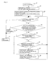
- FIG. 3 shows an example of a telegram synthesizing procedure performed by the field control terminal according to the example.
- FIG. 1 shows a configuration of a computerized interlocking system according to an embodiment of the present invention during a switching test.
- An interlocking logic section 6 is connected to a field control terminal 7 via a LAN 20.
- a testing interlocking logic section 3 is also connected to the LAN 20.
- the interlocking logic section 6 and the testing interlocking logic section 3 produce a control command for controlling a field apparatus 12, such as a railway switch and a signal, and outputs the control command to the field control terminal 7 via the LAN 20.
- a field apparatus 12 such as a railway switch and a signal
- the field apparatus 12 may be a field apparatus 12a that is directly controlled by the field control terminal 7 and a field apparatus 12b that is controlled via a switching device 9.
- the switching device 9 switches the destination of the control command between the field apparatus 12b and the simulator means 10.
- the interlocking logic section 6 produces, in control information producing section 14a, control information for controlling the field apparatus 12 in safety, which concerns the current field apparatus 12, and performs a normal control, such as revenue train operation during the daytime.
- the testing interlocking logic section 3 produces, in testing control information producing section 14b, control information for controlling the modified field apparatus 12 in safety and performs a control for a test concerning the modification.
- the interlocking logic section 6 has two operation modes: a "control mode” in which the interlocking logic section 6 performs the normal control; and a "halt mode” in which the interlocking logic section 6 is in a halt condition.
- the testing interlocking logic section 3 has three operation modes: a "follow mode” in which the testing interlocking logic section 3 performs a control by following the operation of the interlocking logic section 6 to avoid interfering with the operation of the interlocking logic section 6 when the interlocking logic section 6 is in operation; an "independent mode” in which the testing interlocking section 3 operates according to a schedule of its own based on post-modification interlocking information when the interlocking logic section 6 is in a halt condition; and a "halt mode” in which the testing interlocking logic section 3 is in a halt condition.
- the field control terminal 7 has modes that are determined by combinations of the operation modes of the interlocking logic section 6 and the testing interlocking logic section 3. Since the interlocking logic section 6 has two operation modes, and the testing interlocking logic section 3 has three operation modes, the field control terminal 7 has six operation modes depending on how those operation modes are combined to each other. The six operation modes are sorted into five operation modes: a following test mode; a normal mode; an independent test mode; an error mode; and a halt mode. The five operation modes will be described in succession in the following.
- FIG. 1 an exemplary configuration of and exemplary outputs from a computerized interlocking system 1 in the case where the interlocking logic section 6 operates in the control mode and the testing interlocking logic section 3 operates in the follow mode will be described.
- the field control terminal 7 operates in the following test mode, as can be seen from FIG. 2.
- the interlocking logic section 6 produces a telegram 30 as a control command destined for the field apparatus 12 and transmits the control command to the field control terminal 7 via the LAN 20.
- the testing interlocking logic section 3 produces a telegram 32 as a control command destined for the field apparatus 12 and transmits the control command to the field control terminal 7 via the LAN 20.
- the interlocking logic section 6 and the testing interlocking logic section 3 inform the field control terminal 7 via the LAN 20 that the interlocking logic section 6 and the testing interlocking logic section 3 operate in the control mode and in the follow mode, respectively.
- the telegrams 30 and 32 contain "output/not-output" information that specifies the presence (1, H or On) or absence (0, L or Off) of control of each field apparatus 12, for example, information about a railway switch that specifies whether the railway switch is turned to a straight track or to a branch track.
- the telegrams 30 and 32 contain "used/not-used” information that specifies whether the "output/not-output” information is output or not for the field apparatus 12, which is associated with each piece of "output/not-output” information.
- the "used/not-used” information is retained by the interlocking logic section 6 or the testing interlocking logic section 3 and specifies the presence or absence of control output to the field apparatus 12 for each of the operation modes. Since the interlocking logic section 6 has only the control mode as the active operation mode, the interlocking logic section 6 retains only control-mode output specifying information 13a as the "used/not-used" information. On the other hand, since the testing interlocking logic section 3 has the follow mode and the independent operation mode as the active operation mode, the testing interlocking logic section 3 retains follow-mode output specifying information 13b and independent-operation-mode output specifying information 13c as the "used/not-used" information.
- the operation mode management section 2 determines that the field apparatus terminal operates in the following test mode according to the mode/state definition shown in FIG. 2.
- the field control terminal 7 uses the telegrams 30 and 32 and the operation mode information about the interlocking logic section 6 and the testing interlocking logic section 3 retained in the operation mode management section 2, the field control terminal 7 synthesizes control information for each field apparatus 12 in a telegram synthesizing/dividing section 4, determines the information for controlling the field apparatus 12 and issues a command to the field apparatus 12 via a control information interface section 5 or to the field apparatus 12 or the simulator means 10 further via the switching device 9.
- the telegram synthesizing/dividing section 4 manages the "used/not-used” information, the "output/not-output” information and "controller" information for each field apparatus 12.
- the "controller” information indicates which of the telegram 30, which is the control command produced by the interlocking logic section 6, and the telegram 32, which is the control command produced by the testing interlocking logic section 3, is used.
- the "controller” information indicates "existing”
- the "controller” information indicates "simulation”.
- the "used/not-used” information and the "output/not-output” information correspond to "used/not-used” and "output/not-output" of the interlocking logic section 6 or the testing interlocking logic section 3, respectively, and are determined by the used/not-used” and "output/not-output” information of the interlocking logic section 6 or the testing interlocking logic section 3 that are retained as the "controller" information.
- a procedure of determining the "controller" information is shown in FIG. 3.
- an initialization step 102 of setting all the values at "not-used” or “not-output” is performed, and then, a step 103 of receiving the telegram 30 produced by the interlocking logic section 6 and the telegram 32 produced by the testing interlocking logic section 3 is performed.
- the "used/not-used” information and the "output/not-output" information contained in the telegram 30, which is a control command from the interlocking logic section 6, are checked in step 106.
- the "controller” information is set at "existing”, and a step 108 of outputting the "used/not-used” information and the "output/not-output” information contained in the telegram 30 is performed. Then, a determination step 104 and the following steps are repeated for the next output yet to be processed.
- the telegram 30 indicates "not-output” in the information checking step 106, then the "used/not-used” information and the "output/not-output” information contained in the telegram 32, which is a control command from the testing interlocking logic section 3, are checked in step 107. If the telegram 32 indicates “output”, since the relevant output is not controlled by the interlocking logic section 6 but controlled by the testing interlocking logic section 3, the "controller" information is set at "simulation”, and a step 109 of outputting the "used/not-used” information and the "output/not-output” information contained in the telegram 32 is performed. Then, the procedure returns to the determination step 104.
- the telegram 32 indicates "not-output" in the information checking step 107, the relevant output is not from the interlocking logic section 6 and the testing interlocking logic section 3. Thus, the values "not-used” and “not-output" set in the initialization step 102 are kept unchanged, and the procedure returns to the determination step 104.
- the information of the field control terminal 7 indicates “existing", "used” and “output”.
- the information of the field control terminal 7 indicates "simulation", "used” and "output”.
- the field control terminal 7 outputs a synthesis telegram 31, which comprises the "used/not-used” information, the "output/not-output” information and the "controller” information determined by the procedure described above, to the field apparatus 12a via the control information interface section 5 or to the field apparatus 12b or the simulator means 10 via the switching device 9.
- control-mode output specifying information 13a and the follow-mode output specifying information 13b is determined in such a manner that both the commands from the interlocking logic section 6 and the testing interlocking logic section 3 to the same field apparatus 12 are not "output", in order to prevent the information from inhibiting the operation of the interlocking logic section 6 and thereby affecting the field apparatus 12 in operation.
- both the telegram 30 produced by the interlocking logic section 6 and the telegram 32 produced by the testing interlocking logic section 3 indicate "output" or not in a step 105. If both the telegram indicate "output”, it indicates an error that, during operation of the interlocking logic section 6 in which the testing interlocking logic section 3 should be in the follow mode, the testing interlocking logic section 3 does not perform control following the operation of the interlocking logic section 6 not to inhibit the operation of the interlocking logic section 6. Thus, an error processing step 110 is performed to inform an error management section 8 of the error.
- the error management section 8 halts the testing interlocking logic section 3, performs a processing using only the telegram 30 from the interlocking logic section 6 by ignoring the telegram 32 from the testing interlocking logic section 3 or halts the output of the field control terminal 7.
- the telegram synthesizing/dividing section 4 since the telegram synthesizing/dividing section 4 retains information that indicates that the interlocking logic section 6 operates in the control mode, and the testing interlocking logic section 3 operates in the follow mode, the telegram synthesizing/dividing section 4 transmits, to an switching information interface 11, an output for switching an output specified as "simulation" in the telegram 31 from the field apparatus 12b to the simulator means 10.
- the switching information interface 11 produces an output that instructs the switching device 9 to switch the output from the control information interface 5 from the field apparatus 12b to the simulator means 10, and the switching device 9 controls the connection target according to the output.
- the switching device 9 may control the connection target without using the operationmode information about the interlocking logic section 6 and the testing interlocking logic section 3 from the telegram synthesizing/dividing section 4. In this case, the switching device 9 is directly informed of the connection target via a connection-target specifying interface 15, and thus, the switching information interface 11 is not necessary.
- the result of the output to the field apparatus 12 or the simulator means 10 is introduced into the field control terminal 7 via the control information interface section 5.
- the result is divided based on the "controller" information contained in the telegram 31 and transmitted individually to the interlocking logic section 6 or the testing interlocking logicsection3. For example, if the "controller" information contained in the telegram 31 indicates “control”, the result is transmitted to the interlocking logic section 6 via the LAN 20, and if the "controller” information indicates “simulation”, the result is transmitted to the testing interlocking logic section 3 via the LAN 20.
- the result may be transmitted to each of the interlocking logic section 6 and the testing interlocking logic section 3 via the LAN 20 without being divided.
- the apparatus when performing a connection test of the testing interlocking logic section 3 and the field apparatus 12, the apparatus according to the present invention can check the operation of the testing interlocking logic section 3 without halting the interlocking logic section 6 or changing any wiring connection even when the interlocking logic section 6 is in operation, such as during the daytime, and the process time and cost of the test carried out in the field apparatus room can be reduced.
- the testing interlocking logic section 3 since the testing interlocking logic section 3 does not operate, the telegram 32 is not produced. In addition, since the operation mode management section 2 does not receive the operation mode information from the testing interlocking logic section 3 via the LAN 20, the operation mode management section 2 determines that the testing interlocking logic section 3 is halted, and that the field apparatus terminal 7 operates in the normal mode according to the mode/state definition shown in FIG. 2.
- the telegram synthesizing/dividing section 4 performs a processing using only the telegram 30, that is, the information from the interlocking logic section 6. Because of the absence of the telegram 32, the determination step 105 relating to the information of the telegram 32 does not determine that both the telegram 30 and the telegram 32 indicate "output". In addition, the result of the determination step 107 is not "output", and there is no possibility that the information from the telegram 32 is output in the step 109. Thus, the field apparatus terminal 7 outputs only the information from the telegram 30 as the telegram 31. At the same time, the telegram 31 does not contain any piece of information that designates the "connection target" as "simulation".
- the computerized interlocking system 1 can operate by allowing only the interlocking logic section 6 to operate under the control mode.
- the computerized interlocking system 1 can shift to the control by only the interlocking logic section 6 without the need of changing any wiring connection, and the process time and cost of the test carried out in the field apparatus room can be reduced.
- the testing interlocking logic section 3 determines the "output/not-output" information contained in the telegram 32 based on the independent-mode output specifying information 13c.
- the independent-mode output specifying information 13c is information that defines an output that allows the testing interlocking logic section 3 to operate independently.
- the operation mode management section 2 since the interlocking logic section 6 does not operate, the telegram 30 is not produced. In addition, since the operation mode management section 2 does not receive the operation mode information from the interlocking logic section 6 via the LAN 20, the operation mode management section 2 determines that the interlocking logic section 6 is halted, and that the field apparatus terminal 7 operates in the independent test mode according to the mode/state definition shown in FIG. 2.
- the telegram synthesizing/dividing section 4 performs a processing using only the telegram 32, that is, the information from the testing interlocking logic section 3. Because of the absence of the telegram 30, the determination step 105 relating to the information of the telegram 30 does not determine that both the telegram 30 and the telegram 32 indicate "output". In addition, the result of the determination step 107 is not "output", and there is no possibility that the information from the telegram 30 is output in the step 109. Thus, the field apparatus terminal 7 outputs only the information from the telegram 32 as the telegram 31. At the same time, the telegram 31 does not contain any piece of information that designates the "connection target" as "control".
- the computerized interlocking system 1 can operate by allowing only the testing interlocking logic section 3 to operate under the independent mode.
- the computerized interlocking system 1 can shift to the control by only the testing interlocking logic section 3 without the need of changing any wiring connection, and the process time and cost of the test carried out in the field apparatus room can be reduced.
- the field control terminal 7 is considered to be in an error state according to the definition shown in FIG. 2.
- the interlocking logic section 6 informs the field control terminal 7, via the LAN 20, of the fact that the operation mode thereof is the control mode.
- the testing interlocking logic section 3 informs the field control terminal 7, via the LAN 20, of the fact that the operation mode thereof is the independent mode.
- testing interlocking logic section 3 Since the testing interlocking logic section 3 operates in the independent mode, not in the follow mode in which the testing interlocking logic section 3 performs control following the operation of the interlocking logic section 6 not to inhibit the operation of the interlocking logic section 6 in the control mode, the operation of the testing interlocking logic section 3 may inhibit the operation of the interlocking logic section 6.
- the operation mode management section 2 receives the operation mode information from the interlocking logic section 6 and the testing interlocking logic section 3 via the LAN 20. Then, if the interlocking logic section 6 operates in the control mode, and the testing interlocking logic section 3 operates in the independent mode, the operation mode management section 2 determines that the field control terminal 7 is in the error state according to the mode/state definition shown in FIG. 2.
- the operation mode management section 2 transmits the operation mode information from the interlocking logic section 6 and the testing interlocking logic section 3, which is considered erroneous, to the error management section 8, and the error management section 8 stores the information transmitted thereto.
- the operation mode management section 2 instructs the telegram synthesizing/dividing section 4 to discard the telegrams 30 and 32. In this way, the telegram synthesizing/dividing section 4 does not accept the telegrams 30 and 32, and thus, does not produce any output to the field apparatus 12 or the switching device 9 shown in the procedure of FIG. 3.
- the field control terminal 7 is considered to be in an error state according to the mode/state definition shown in FIG. 2.
- the interlocking logic section 6 cannot transmit the operation mode information to the field control terminal 7 via the LAN 20.
- the testing interlocking logic section 3 informs, via the LAN 20, the field control terminal 7 of the fact that the operation mode thereof is the independent mode.
- testing interlocking logic section 3 Since the testing interlocking logic section 3 operates in the test mode, not in the independent mode in which the testing interlocking logic section 3 operates independently, the testing interlocking logic section 3 may be unable to safely control the field apparatus 12 by itself.
- the operation mode management section 2 receives the operation mode information from the interlocking logic section 6 and the testing interlocking logic section 3 via the LAN 20. Then, if the interlocking logic section 6 is halted, and the testing interlocking logic section 3 operates in the followmode, the operationmodemanagement section 2 determines that the field control terminal 7 is in the error state according to the mode/state definition shown in FIG. 2. The following process is the same as in the case of the error state described above.
- the field control terminal 7 does not receive the operation mode information of the interlocking logic section 6 and the testing interlocking logic section 3 via the LAN 20, and therefore, is considered to be in the error state according to the condition of combination of operation modes shown in FIG. 2. In this case, the field control terminal 7 receives neither the telegram 30 nor the telegram 32, and thus, does not transmit any output to the field apparatus 12.
- the field control terminal 7 can safely control the field apparatus 12 for all the combinations of operation modes of the interlocking logic section 6 and the testing interlocking logic section 3.
- the present invention provides a computerized interlocking system, comprising: an interlocking logic section that produces a control command to a plurality of railway signaling field apparatus, including a railway switch, a signal and a contact output; a field control terminal connected to the interlocking logic section via a communication line in which a control calculation section that produces a control output to the plurality of railway signaling field apparatus is implemented; and simulator means capable of simulating the functions of the railway signaling field apparatus during testing, characterized in that the computerized interlocking system further comprises a testing interlocking logic section that is connected to the plurality of field control terminals via the communication line and has, as an operation mode, a follow mode in which the testing interlocking logic section performs control following the operation of the interlocking logic section not to inhibit the operation of the interlocking logic section, either or both of the interlocking logic section and the testing interlocking logic section outputs a control command for one or more of the plurality of railway signaling field apparatus to the field control terminal along
- the field control terminal outputs no control command to the one or more field apparatus or suppresses any output in the case where the interlocking logic section produces no output, and the testing interlocking logic section operates in the follow mode.
- the testing interlocking logic section has, as an operation mode, an independent mode in which the testing interlocking logic section performs control independently, either orboth of the interlocking logic section and the testing interlocking logic section outputs a control command for the one or more field apparatus to the field control terminal along with output presence/absence information about the control command, and in the case where the interlocking logic section produces no output, and the testing interlocking logic section produces a control command in the independent mode, the field control terminal operates in an independent test mode and outputs the control command from the testing interlocking logic section of control commands for the one or more field apparatus.
- the field control terminal outputs no control command to the one or more field apparatus or suppresses any output in the case where the interlocking logic section produces an output or is in operation, and the testing interlocking logic section operates in the independent mode.
- the field control terminal is connected, via switching means, to the plurality of railway signaling field apparatus and the simulator means capable of simulating the operations of the plurality of railway signaling field apparatus, the field control terminal transmits operation mode information about the testing interlocking logic section to the switching means, and the switching means is connected to the simulator means in the case where the operation mode information about the testing interlocking logic section indicates that the operation mode of the testing interlocking logic section is the follow mode, and to the plurality of railway signaling field apparatus in the case where the operation mode information indicates that the operation mode of the testing interlocking logic section is the independent mode.
- the field control terminal is connected to the plurality of railway signaling field apparatus and the simulator means that simulates the operations of the plurality of railway signaling field apparatus via the switching means, and the switching means has an interface for specifying whether the switching means is connected to the simulator means or the railway signaling field apparatus.
- the field control terminal outputs no control command to the plurality of railway signaling field apparatus or suppresses any output in the case where both the interlocking logic section and the testing interlocking logic section designate an output.
- the present invention provides a testing apparatus, comprising: a field control terminal in which an interlocking logic section that produces a control command to a plurality of railway signaling field apparatus, including a railway switch, a signal and a contact output, and a control calculation section that is connected to the interlocking logic section via a communication line and produces a control output to the plurality of railway signaling field apparatus are implemented, characterized in that the computerized interlocking system further comprises a testing interlocking logic section that is connected to the plurality of field control terminals via the communication line and has, as an operation mode, a followmode in which the testing interlocking logic section performs control following the operation of the interlocking logic section not to inhibit the operation of the interlocking logic section, either or both of the interlocking logic section and the testing interlocking logic section outputs a control command for one or more of the plurality of railway signaling field apparatus to the field control terminal along with output presence/absence information about the control command, and in the case where the interlocking logic section produces an output or is
- the present invention provides a testing method that produces a control output to a plurality of railway signaling field apparatus, includingarailwayswitch, a signal and a contact output, via a communication line and simulates the functions of the railway signaling field apparatus during testing, characterized in that when either or both of a control command and a testing control command for one or more of the plurality of railway signaling field apparatus are transmitted for controlling and for performing a test, the testing control command is a follow-mode test command that does not inhibit the control command or an independent-mode test command for performing an independent test when there is no control command .
Landscapes
- Engineering & Computer Science (AREA)
- Mechanical Engineering (AREA)
- Architecture (AREA)
- Civil Engineering (AREA)
- Structural Engineering (AREA)
- Train Traffic Observation, Control, And Security (AREA)
Abstract
Description
- The present invention relates to a computerized interlocking system for controlling a railway signal. In particular, it relates to a computerized interlocking system in the case where an existing field installation is modified or where the function of the computerized interlocking system is expanded, and a testing method therefor.
- In the following, a method of modifying the function of a conventional computerized interlocking system will be described. When installing a new computerized interlocking system or renewing all installations, it is common practice to install the new computerized interlocking system adjacent to the existing installations, connects the new computerized interlocking system to field simulator means to check the functionality of the system, and then, during a time period in which the existing installations are out of service, connects the new computerized interlocking system to the existing installations for testing.
- Furthermore, when partially modifying the existing computerized interlocking system, adding a field installation or modifying an existing field installation, the computerized interlocking system is connected to the wiring of the modified installation, the test is performed, and then the original state is recovered during a time period in which the existing installation is out of service.
- As a method of testing an existing installation in the field when the installation is in operation, the patent reference 1 discloses a method of performing a test by linking field simulator means to a new computerized inter locking system via simulator communication means in a field apparatus, for example.
- Furthermore, as a method of disconnecting field simulator means and interconnecting a new interlocking logic section and a field apparatus when performing a test by connecting the new interlocking logic section to an existing installation, the
patent reference 2 discloses a method of using an optical switch for switching between a new computerized interlocking apparatus and an existing computerized interlocking apparatus in the case where communication means is optical communication means. - [Patent Reference 1] Japanese Patent Laid-Open No. 2003-327122
- [Patent Reference 2] Japanese Patent Laid-Open No. 2000-52989
- In modification of a conventional computerized interlocking system, an updated system or a testing system cannot be connected to the communication line of the existing computerized interlocking system to make them operate in parallel during operation of an exiting installation. For example, the method of performing a test by linking field simulator means to a new computerized interlocking system via simulator communication means in a field apparatus has a problem that the test can be performed only in a limited time period in which the existing installation is out of service, such as in the nighttime.
- Furthermore, the method of using an optical switch for switching between a new computerized interlocking apparatus and an existing computerized interlocking apparatus, which has been described above as a method of disconnecting field simulator means and interconnecting a new interlocking logic section and a field apparatus when performing a test by connecting the new interlocking logic section to an existing installation, requires a switch to be inserted to each cable or the connection of the cable to be changed for each test. In the case where a switch is inserted to each cable, there is a problem that wiring requires a high cost. On the other hand, in the case where the connection of the cable is changed for each test, the connection has to be changed from the simulator means to the field apparatus before test, and once the test is completed, the connection has to be changed again from the field apparatus to the simulator means. Thus, there is a problem that a cost for the changing occurs. In addition, the continuity has to be checked after the original connection is recovered, so that there is a problem that the test time is reduced accordingly.
- An object of the present invention is to provide a computerized interlocking system that controls a railway signaling field apparatus, a computerized interlocking system that is suitable for simplifying addition to or modification of a railway signaling field apparatus, a testing apparatus therefor and a testing method therefor.
- In order to achieve the object, according to the present invention, an interlocking logic section that produces a control command for a plurality of currently used railway signaling field apparatus, such as a railway switch, a signal and a contact output, a testing interlocking logic section for performing a test via an existing communication line in the railway signaling field apparatus, which is connected to and controlled by the interlocking logic apparatus via the communication line, when either or both of the interlocking logic section and the railway signaling field apparatus are modified, the railway signaling field apparatus to be modified or added, and simulator means are connected to each other. The interlocking logic section and the testing interlocking logic section produces, for each control command for the field apparatus, "output/not-output" information, which is a control command for the field apparatus, such as a switch command for the railway switch, and "used/not-used" information for indicating the presence or absence of output of the control command for the field apparatus and transmits the control command and these pieces of information to the field control terminal. The field control terminal refers to "existing/testing" information that specifies which of the interlocking logic section and the testing interlocking logic section has produced the received control command, information indicating the presence or absence of output of the control command for the field apparatus, which is associated with each control command, and information indicating the presence or absence of output of the control command to the field apparatus, which is associated with each of the control commands, and controls the field apparatus and the simulator means.
- For information for which the interlocking logic section designates "output" in the control commands, the "used/not-used" information from the interlocking logic section, which is a control command from the interlocking logic section, is adopted. This permits the interlocking logic section to perform control of the existing installation.
- If the testing interlocking logic section designates "output" for information for which the interlocking logic section designates "not-output" in the control commands, the "used/not-used" information from the testing interlocking logic section, which is a control command from the testing interlocking logic section, is adopted. This permits the interlocking logic section and the testing interlocking logic section to operate in parallel without affecting the control by the interlocking logic section.
- When the operation of the interlocking logic section is halted, if the testing interlocking logic section designates "output", the "used/not-used" information from the testing interlocking logic section, which is a control command from the testing interlocking logic section, is adopted. This permits the test using only the testing interlocking logic section to be performed without switching the wiring connection between the interlocking logic section and the testing interlocking logic section.
- By using the system configuration according to the present invention, a testing
interlocking logic section 3 can be always connected to an existinginterlocking logic section 6 via aLAN 20, and the operation of the testinginterlocking logic section 3 having amodified interlocking systemmountedthereon can be checked even during operation of theinterlocking logic section 6. Thus, when the connection between the testing interlocking logic section and the field apparatus is tested by halting the existing interlocking logic section, there is no need of changing the wiring connection, and a part of the test can be performed in the daytime. In addition, the time that would be conventionally required for wiring change or wiring checking after wiring change can be omitted, and the time and cost required for performing a test in a field apparatus room when updating the computerized interlocking system can be reduced. - FIG. 1 is a drawing for illustrating a configuration of a computerized interlocking system according to an example.
- FIG. 2 shows an exemplary relationship among operation modes of an interlocking logic section, a testing interlocking logic section and a field control terminal according to the example.
- FIG. 3 shows an example of a telegram synthesizing procedure performed by the field control terminal according to the example.
- A best mode for carrying out the present invention will be described.
- In the following, a computerized interlocking system, a testing apparatus and a testing method according to embodiments of the present invention will be described with reference to the drawings.
- An example of the present invention will be described. FIG. 1 shows a configuration of a computerized interlocking system according to an embodiment of the present invention during a switching test. An
interlocking logic section 6 is connected to afield control terminal 7 via aLAN 20. A testinginterlocking logic section 3 is also connected to theLAN 20. Theinterlocking logic section 6 and the testinginterlocking logic section 3 produce a control command for controlling afield apparatus 12, such as a railway switch and a signal, and outputs the control command to thefield control terminal 7 via theLAN 20. - The
field apparatus 12 may be afield apparatus 12a that is directly controlled by thefield control terminal 7 and afield apparatus 12b that is controlled via a switching device 9. The switching device 9 switches the destination of the control command between thefield apparatus 12b and the simulator means 10. - The
interlocking logic section 6 produces, in control information producing section 14a, control information for controlling thefield apparatus 12 in safety, which concerns thecurrent field apparatus 12, and performs a normal control, such as revenue train operation during the daytime. The testinginterlocking logic section 3 produces, in testing controlinformation producing section 14b, control information for controlling themodified field apparatus 12 in safety and performs a control for a test concerning the modification. - Combinations of operation modes of the
interlocking logic section 6, the testinginterlocking logic section 3 and thefield control terminal 7 in this example are shown in FIG. 2. Theinterlocking logic section 6 has two operation modes: a "control mode" in which theinterlocking logic section 6 performs the normal control; and a "halt mode" in which theinterlocking logic section 6 is in a halt condition. - The testing
interlocking logic section 3 has three operation modes: a "follow mode" in which the testinginterlocking logic section 3 performs a control by following the operation of theinterlocking logic section 6 to avoid interfering with the operation of theinterlocking logic section 6 when theinterlocking logic section 6 is in operation; an "independent mode" in which thetesting interlocking section 3 operates according to a schedule of its own based on post-modification interlocking information when theinterlocking logic section 6 is in a halt condition; and a "halt mode" in which the testinginterlocking logic section 3 is in a halt condition. - The
field control terminal 7 has modes that are determined by combinations of the operation modes of theinterlocking logic section 6 and the testinginterlocking logic section 3. Since theinterlocking logic section 6 has two operation modes, and the testinginterlocking logic section 3 has three operation modes, thefield control terminal 7 has six operation modes depending on how those operation modes are combined to each other. The six operation modes are sorted into five operation modes: a following test mode; a normal mode; an independent test mode; an error mode; and a halt mode. The five operation modes will be described in succession in the following. - With reference to FIG. 1, an exemplary configuration of and exemplary outputs from a computerized interlocking system 1 in the case where the
interlocking logic section 6 operates in the control mode and the testinginterlocking logic section 3 operates in the follow mode will be described. In this case, thefield control terminal 7 operates in the following test mode, as can be seen from FIG. 2. - The
interlocking logic section 6 produces atelegram 30 as a control command destined for thefield apparatus 12 and transmits the control command to thefield control terminal 7 via theLAN 20. Similarly, the testinginterlocking logic section 3 produces atelegram 32 as a control command destined for thefield apparatus 12 and transmits the control command to thefield control terminal 7 via theLAN 20. At the same time, theinterlocking logic section 6 and the testinginterlocking logic section 3 inform thefield control terminal 7 via theLAN 20 that theinterlocking logic section 6 and the testinginterlocking logic section 3 operate in the control mode and in the follow mode, respectively. - The
telegrams field apparatus 12, for example, information about a railway switch that specifies whether the railway switch is turned to a straight track or to a branch track. - In addition to the "output/not-output" information concerning the presence or absence of control of the
field apparatus 12, thetelegrams field apparatus 12, which is associated with each piece of "output/not-output" information. - The "used/not-used" information is retained by the
interlocking logic section 6 or the testinginterlocking logic section 3 and specifies the presence or absence of control output to thefield apparatus 12 for each of the operation modes. Since theinterlocking logic section 6 has only the control mode as the active operation mode, theinterlocking logic section 6 retains only control-modeoutput specifying information 13a as the "used/not-used" information. On the other hand, since the testinginterlocking logic section 3 has the follow mode and the independent operation mode as the active operation mode, the testinginterlocking logic section 3 retains follow-modeoutput specifying information 13b and independent-operation-modeoutput specifying information 13c as the "used/not-used" information. - Information indicating that the interlocking
logic section 6 and the testinginterlocking logic section 3 operate in the control mode and in the follow mode, respectively, is retained in an operationmode management section 2 in thefield control terminal 7. From the information indicating that the interlockinglogic section 6 and the testinginterlocking logic section 3 operate in the control mode and in the follow mode, respectively, the operationmode management section 2 determines that the field apparatus terminal operates in the following test mode according to the mode/state definition shown in FIG. 2. - Using the
telegrams logic section 6 and the testinginterlocking logic section 3 retained in the operationmode management section 2, thefield control terminal 7 synthesizes control information for eachfield apparatus 12 in a telegram synthesizing/dividing section 4, determines the information for controlling thefield apparatus 12 and issues a command to thefield apparatus 12 via a controlinformation interface section 5 or to thefield apparatus 12 or the simulator means 10 further via the switching device 9. - The telegram synthesizing/
dividing section 4 manages the "used/not-used" information, the "output/not-output" information and "controller" information for eachfield apparatus 12. - The "controller" information indicates which of the
telegram 30, which is the control command produced by the interlockinglogic section 6, and thetelegram 32, which is the control command produced by the testinginterlocking logic section 3, is used. For example, in the case where thetelegram 30 produced by the interlockinglogic section 6 is used, the "controller" information indicates "existing", and in the case where thetelegram 32 produced by the testinginterlocking logic section 3 is used, the "controller" information indicates "simulation". The "used/not-used" information and the "output/not-output" information correspond to "used/not-used" and "output/not-output" of the interlockinglogic section 6 or the testinginterlocking logic section 3, respectively, and are determined by the used/not-used" and "output/not-output" information of the interlockinglogic section 6 or the testinginterlocking logic section 3 that are retained as the "controller" information. - A procedure of determining the "controller" information is shown in FIG. 3. First, an
initialization step 102 of setting all the values at "not-used" or "not-output" is performed, and then, astep 103 of receiving thetelegram 30 produced by the interlockinglogic section 6 and thetelegram 32 produced by the testinginterlocking logic section 3 is performed. Then, of all the outputs, first, the "used/not-used" information and the "output/not-output" information contained in thetelegram 30, which is a control command from the interlockinglogic section 6, are checked instep 106. If thetelegram 30 indicates "output", since the relevant output is controlled by the interlockinglogic section 6, the "controller" information is set at "existing", and astep 108 of outputting the "used/not-used" information and the "output/not-output" information contained in thetelegram 30 is performed. Then, adetermination step 104 and the following steps are repeated for the next output yet to be processed. - If the
telegram 30 indicates "not-output" in theinformation checking step 106, then the "used/not-used" information and the "output/not-output" information contained in thetelegram 32, which is a control command from the testinginterlocking logic section 3, are checked instep 107. If thetelegram 32 indicates "output", since the relevant output is not controlled by the interlockinglogic section 6 but controlled by the testinginterlocking logic section 3, the "controller" information is set at "simulation", and astep 109 of outputting the "used/not-used" information and the "output/not-output" information contained in thetelegram 32 is performed. Then, the procedure returns to thedetermination step 104. - If the
telegram 32 indicates "not-output" in theinformation checking step 107, the relevant output is not from the interlockinglogic section 6 and the testinginterlocking logic section 3. Thus, the values "not-used" and "not-output" set in theinitialization step 102 are kept unchanged, and the procedure returns to thedetermination step 104. - For example, in the case where the information from the interlocking
logic section 6 indicates "used" and "output", and the information from the testinginterlocking logic section 3 indicates "not-used" and "not-output", the information of thefield control terminal 7 indicates "existing", "used" and "output". Similarly, in the case where the information from the interlockinglogic section 6 indicates "not-used" and "not-output", and the information from the testinginterlocking logic section 3 indicates "used" and "output", the information of thefield control terminal 7 indicates "simulation", "used" and "output". - The
field control terminal 7 outputs a synthesis telegram 31, which comprises the "used/not-used" information, the "output/not-output" information and the "controller" information determined by the procedure described above, to thefield apparatus 12a via the controlinformation interface section 5 or to thefield apparatus 12b or the simulator means 10 via the switching device 9. - When the testing
interlocking logic section 3 is operating in the follow mode, the control-modeoutput specifying information 13a and the follow-modeoutput specifying information 13b is determined in such a manner that both the commands from the interlockinglogic section 6 and the testinginterlocking logic section 3 to thesame field apparatus 12 are not "output", in order to prevent the information from inhibiting the operation of the interlockinglogic section 6 and thereby affecting thefield apparatus 12 in operation. - In the procedure shown in FIG. 3, it is checked whether both the
telegram 30 produced by the interlockinglogic section 6 and thetelegram 32 produced by the testinginterlocking logic section 3 indicate "output" or not in astep 105. If both the telegram indicate "output", it indicates an error that, during operation of the interlockinglogic section 6 in which the testinginterlocking logic section 3 should be in the follow mode, the testinginterlocking logic section 3 does not perform control following the operation of the interlockinglogic section 6 not to inhibit the operation of the interlockinglogic section 6. Thus, anerror processing step 110 is performed to inform anerror management section 8 of the error. Theerror management section 8 halts the testinginterlocking logic section 3, performs a processing using only thetelegram 30 from the interlockinglogic section 6 by ignoring thetelegram 32 from the testinginterlocking logic section 3 or halts the output of thefield control terminal 7. - In addition, since the telegram synthesizing/dividing
section 4 retains information that indicates that the interlockinglogic section 6 operates in the control mode, and the testinginterlocking logic section 3 operates in the follow mode, the telegram synthesizing/dividingsection 4 transmits, to an switchinginformation interface 11, an output for switching an output specified as "simulation" in the telegram 31 from thefield apparatus 12b to the simulator means 10. The switchinginformation interface 11 produces an output that instructs the switching device 9 to switch the output from thecontrol information interface 5 from thefield apparatus 12b to the simulator means 10, and the switching device 9 controls the connection target according to the output. - Alternatively, the switching device 9 may control the connection target without using the operationmode information about the interlocking
logic section 6 and the testinginterlocking logic section 3 from the telegram synthesizing/dividingsection 4. In this case, the switching device 9 is directly informed of the connection target via a connection-target specifying interface 15, and thus, the switchinginformation interface 11 is not necessary. - The result of the output to the
field apparatus 12 or the simulator means 10 is introduced into thefield control terminal 7 via the controlinformation interface section 5. The result is divided based on the "controller" information contained in the telegram 31 and transmitted individually to the interlockinglogic section 6 or the testing interlocking logicsection3. For example, if the "controller" information contained in the telegram 31 indicates "control", the result is transmitted to the interlockinglogic section 6 via theLAN 20, and if the "controller" information indicates "simulation", the result is transmitted to the testinginterlocking logic section 3 via theLAN 20. - Furthermore, alternatively, the result may be transmitted to each of the interlocking
logic section 6 and the testinginterlocking logic section 3 via theLAN 20 without being divided. - Thus, when performing a connection test of the testing
interlocking logic section 3 and thefield apparatus 12, the apparatus according to the present invention can check the operation of the testinginterlocking logic section 3 without halting the interlockinglogic section 6 or changing any wiring connection even when the interlockinglogic section 6 is in operation, such as during the daytime, and the process time and cost of the test carried out in the field apparatus room can be reduced. - Now, with reference to FIG. 2, a case where the interlocking
logic section 6 operates in the control mode, and the testinginterlocking logic section 3 is halted will be described with regard to the difference from the case where thefield apparatus terminal 7 operates in the following test mode described above. In this case, thefield control terminal 7 operates in the normal mode, as can be seen from FIG. 2. - In this case, since the testing
interlocking logic section 3 does not operate, thetelegram 32 is not produced. In addition, since the operationmode management section 2 does not receive the operation mode information from the testinginterlocking logic section 3 via theLAN 20, the operationmode management section 2 determines that the testinginterlocking logic section 3 is halted, and that thefield apparatus terminal 7 operates in the normal mode according to the mode/state definition shown in FIG. 2. - Since the
telegram 32 is not produced, the telegram synthesizing/dividingsection 4 performs a processing using only thetelegram 30, that is, the information from the interlockinglogic section 6. Because of the absence of thetelegram 32, thedetermination step 105 relating to the information of thetelegram 32 does not determine that both thetelegram 30 and thetelegram 32 indicate "output". In addition, the result of thedetermination step 107 is not "output", and there is no possibility that the information from thetelegram 32 is output in thestep 109. Thus, thefield apparatus terminal 7 outputs only the information from thetelegram 30 as the telegram 31. At the same time, the telegram 31 does not contain any piece of information that designates the "connection target" as "simulation". - Furthermore, in the case where the result of the output is divided and the divisional results are transmitted to the interlocking
logic section 6 or the testinginterlocking logic section 3, all the results are transmitted to the interlockinglogic section 6, since the telegram 31 does not contain any piece of information that designates "simulation". - Thus, in the case where the testing
interlocking logic section 3 is halted, the computerized interlocking system 1 can operate by allowing only the interlockinglogic section 6 to operate under the control mode. Thus, when the test is completed, the computerized interlocking system 1 can shift to the control by only the interlockinglogic section 6 without the need of changing any wiring connection, and the process time and cost of the test carried out in the field apparatus room can be reduced. - Now, with reference to FIG. 2, a case where the interlocking
logic section 6 is halted, and the testinginterlocking logic section 3 operates in the independent mode will be described with regard to the difference from the case where thefield apparatus terminal 7 operates in the following test mode described above. In this case, thefield control terminal 7 operates in the independent test mode, as can be seen from FIG. 2. - The testing
interlocking logic section 3 determines the "output/not-output" information contained in thetelegram 32 based on the independent-modeoutput specifying information 13c. The independent-modeoutput specifying information 13c is information that defines an output that allows the testinginterlocking logic section 3 to operate independently. - In this case, since the interlocking
logic section 6 does not operate, thetelegram 30 is not produced. In addition, since the operationmode management section 2 does not receive the operation mode information from the interlockinglogic section 6 via theLAN 20, the operationmode management section 2 determines that the interlockinglogic section 6 is halted, and that thefield apparatus terminal 7 operates in the independent test mode according to the mode/state definition shown in FIG. 2. - Since the
telegram 30 is not produced, the telegram synthesizing/dividingsection 4 performs a processing using only thetelegram 32, that is, the information from the testinginterlocking logic section 3. Because of the absence of thetelegram 30, thedetermination step 105 relating to the information of thetelegram 30 does not determine that both thetelegram 30 and thetelegram 32 indicate "output". In addition, the result of thedetermination step 107 is not "output", and there is no possibility that the information from thetelegram 30 is output in thestep 109. Thus, thefield apparatus terminal 7 outputs only the information from thetelegram 32 as the telegram 31. At the same time, the telegram 31 does not contain any piece of information that designates the "connection target" as "control". - Furthermore, in the case where the result of the output is divided and the divisional results are transmitted to the interlocking
logic section 6 or the testinginterlocking logic section 3, all the results are transmitted to the testinginterlocking logic section 3, since the telegram 31 does not contain any piece of information that designates "control". - Thus, in the case where the interlocking
logic section 6 is halted, the computerized interlocking system 1 can operate by allowing only the testinginterlocking logic section 3 to operate under the independent mode. Thus, when starting the test, the computerized interlocking system 1 can shift to the control by only the testinginterlocking logic section 3 without the need of changing any wiring connection, and the process time and cost of the test carried out in the field apparatus room can be reduced. - Now, a case where the interlocking
logic section 6 operates in the control mode, and the testinginterlocking logic section 3 operates in the independent mode will be described. In this case, thefield control terminal 7 is considered to be in an error state according to the definition shown in FIG. 2. - In this case, the interlocking
logic section 6 informs thefield control terminal 7, via theLAN 20, of the fact that the operation mode thereof is the control mode. Similarly, the testinginterlocking logic section 3 informs thefield control terminal 7, via theLAN 20, of the fact that the operation mode thereof is the independent mode. - Since the testing
interlocking logic section 3 operates in the independent mode, not in the follow mode in which the testinginterlocking logic section 3 performs control following the operation of the interlockinglogic section 6 not to inhibit the operation of the interlockinglogic section 6 in the control mode, the operation of the testinginterlocking logic section 3 may inhibit the operation of the interlockinglogic section 6. - Thus, the operation
mode management section 2 receives the operation mode information from the interlockinglogic section 6 and the testinginterlocking logic section 3 via theLAN 20. Then, if the interlockinglogic section 6 operates in the control mode, and the testinginterlocking logic section 3 operates in the independent mode, the operationmode management section 2 determines that thefield control terminal 7 is in the error state according to the mode/state definition shown in FIG. 2. - In the case where the
field control terminal 7 is in the error state, the operationmode management section 2 transmits the operation mode information from the interlockinglogic section 6 and the testinginterlocking logic section 3, which is considered erroneous, to theerror management section 8, and theerror management section 8 stores the information transmitted thereto. In addition, the operationmode management section 2 instructs the telegram synthesizing/dividingsection 4 to discard thetelegrams section 4 does not accept thetelegrams field apparatus 12 or the switching device 9 shown in the procedure of FIG. 3. - Thus, it is possible to avoid a situation in which the interlocking logic section operates in the control mode, and at the same time, the testing
interlocking logic section 3 operates in the independent test mode, thereby preventing any operation that can compromise the safety of thefield apparatus 12. - Now, a case where the interlocking
logic section 6 is halted, and the testinginterlocking logic section 3 operates in the follow mode will be described. In this case, thefield control terminal 7 is considered to be in an error state according to the mode/state definition shown in FIG. 2. - In this case, the interlocking
logic section 6 cannot transmit the operation mode information to thefield control terminal 7 via theLAN 20. On the other hand, the testinginterlocking logic section 3 informs, via theLAN 20, thefield control terminal 7 of the fact that the operation mode thereof is the independent mode. - Since the testing
interlocking logic section 3 operates in the test mode, not in the independent mode in which the testinginterlocking logic section 3 operates independently, the testinginterlocking logic section 3 may be unable to safely control thefield apparatus 12 by itself. - Thus, the operation
mode management section 2 receives the operation mode information from the interlockinglogic section 6 and the testinginterlocking logic section 3 via theLAN 20. Then, if the interlockinglogic section 6 is halted, and the testinginterlocking logic section 3 operates in the followmode, theoperationmodemanagement section 2 determines that thefield control terminal 7 is in the error state according to the mode/state definition shown in FIG. 2. The following process is the same as in the case of the error state described above. - In the case where both the interlocking
logic section 6 and the testinginterlocking logic section 3 are halted, thefield control terminal 7 does not receive the operation mode information of the interlockinglogic section 6 and the testinginterlocking logic section 3 via theLAN 20, and therefore, is considered to be in the error state according to the condition of combination of operation modes shown in FIG. 2. In this case, thefield control terminal 7 receives neither thetelegram 30 nor thetelegram 32, and thus, does not transmit any output to thefield apparatus 12. - Thus, in the case where the interlocking
logic section 6 and the testinginterlocking logic section 3 are halted, it is possible to prevent any operation that can compromise the safety of thefield apparatus 12 by preventing any output from being transmitted to thefield apparatus 12. - As described above, the
field control terminal 7 can safely control thefield apparatus 12 for all the combinations of operation modes of the interlockinglogic section 6 and the testinginterlocking logic section 3. - As described above with reference to examples, the present invention provides a computerized interlocking system, comprising: an interlocking logic section that produces a control command to a plurality of railway signaling field apparatus, including a railway switch, a signal and a contact output; a field control terminal connected to the interlocking logic section via a communication line in which a control calculation section that produces a control output to the plurality of railway signaling field apparatus is implemented; and simulator means capable of simulating the functions of the railway signaling field apparatus during testing, characterized in that the computerized interlocking system further comprises a testing interlocking logic section that is connected to the plurality of field control terminals via the communication line and has, as an operation mode, a follow mode in which the testing interlocking logic section performs control following the operation of the interlocking logic section not to inhibit the operation of the interlocking logic section, either or both of the interlocking logic section and the testing interlocking logic section outputs a control command for one or more of the plurality of railway signaling field apparatus to the field control terminal along with output presence/absence information about the control command, and in the case where the interlocking logic section outputs a control command, and the testing interlocking logic section is in the follow mode or produces no output, the field control terminal outputs the control command from the interlocking logic section of control commands for the one or more field apparatus.
- In addition, in the computerized interlocking system according to the present invention, the field control terminal outputs no control command to the one or more field apparatus or suppresses any output in the case where the interlocking logic section produces no output, and the testing interlocking logic section operates in the follow mode.
- In addition, in the computerized interlocking system according to the present invention, the testing interlocking logic section has, as an operation mode, an independent mode in which the testing interlocking logic section performs control independently, either orboth of the interlocking logic section and the testing interlocking logic section outputs a control command for the one or more field apparatus to the field control terminal along with output presence/absence information about the control command, and in the case where the interlocking logic section produces no output, and the testing interlocking logic section produces a control command in the independent mode, the field control terminal operates in an independent test mode and outputs the control command from the testing interlocking logic section of control commands for the one or more field apparatus.
- In addition, in the computerized interlocking system according to the present invention, the field control terminal outputs no control command to the one or more field apparatus or suppresses any output in the case where the interlocking logic section produces an output or is in operation, and the testing interlocking logic section operates in the independent mode.
- In addition, in the computerized interlocking system according to the present invention, the field control terminal is connected, via switching means, to the plurality of railway signaling field apparatus and the simulator means capable of simulating the operations of the plurality of railway signaling field apparatus, the field control terminal transmits operation mode information about the testing interlocking logic section to the switching means, and the switching means is connected to the simulator means in the case where the operation mode information about the testing interlocking logic section indicates that the operation mode of the testing interlocking logic section is the follow mode, and to the plurality of railway signaling field apparatus in the case where the operation mode information indicates that the operation mode of the testing interlocking logic section is the independent mode.
- In addition, in the computerized interlocking system according to the present invention, the field control terminal is connected to the plurality of railway signaling field apparatus and the simulator means that simulates the operations of the plurality of railway signaling field apparatus via the switching means, and the switching means has an interface for specifying whether the switching means is connected to the simulator means or the railway signaling field apparatus.
- In addition, in the computerized interlocking system according to the present invention, the field control terminal outputs no control command to the plurality of railway signaling field apparatus or suppresses any output in the case where both the interlocking logic section and the testing interlocking logic section designate an output.
- Furthermore, the present invention provides a testing apparatus, comprising: a field control terminal in which an interlocking logic section that produces a control command to a plurality of railway signaling field apparatus, including a railway switch, a signal and a contact output, and a control calculation section that is connected to the interlocking logic section via a communication line and produces a control output to the plurality of railway signaling field apparatus are implemented, characterized in that the computerized interlocking system further comprises a testing interlocking logic section that is connected to the plurality of field control terminals via the communication line and has, as an operation mode, a followmode in which the testing interlocking logic section performs control following the operation of the interlocking logic section not to inhibit the operation of the interlocking logic section, either or both of the interlocking logic section and the testing interlocking logic section outputs a control command for one or more of the plurality of railway signaling field apparatus to the field control terminal along with output presence/absence information about the control command, and in the case where the interlocking logic section produces an output or is in operation, and the testing interlocking logic section operates in an independent mode in which the testing interlocking logic section performs control independently, the field control terminal outputs none of control commands for the one or more field apparatus.
- Furthermore, the present invention provides a testing method that produces a control output to a plurality of railway signaling field apparatus, includingarailwayswitch, a signal and a contact output, via a communication line and simulates the functions of the railway signaling field apparatus during testing, characterized in that when either or both of a control command and a testing control command for one or more of the plurality of railway signaling field apparatus are transmitted for controlling and for performing a test, the testing control command is a follow-mode test command that does not inhibit the control command or an independent-mode test command for performing an independent test when there is no control command .
Claims (9)
- A computerized interlocking system, comprising:an interlocking logic section that produces a control command to a plurality of railway signaling field apparatus, including a railway switch, a signal and a contact output;a field control terminal connected to said interlocking logic section via a communication line in which a control calculation section that produces a control output to said plurality of railway signaling field apparatus is implemented; andsimulator means capable of simulating the functions of said railway signaling field apparatus during testing,characterized in that the computerized interlocking system further comprises a testing interlocking logic section that is connected to said plurality of field control terminals via said communication line and has, as an operation mode, a follow mode in which the testing interlocking logic section performs control following the operation of said interlocking logic section not to inhibit the operation of the interlocking logic section,
either or both of said interlocking logic section and said testing interlocking logic section outputs a control command for one or more of said plurality of railway signaling field apparatus to said field control terminal along with output presence/absence information about the control command, and
in the case where said interlocking logic section outputs a control command, and said testing interlocking logic section is in the follow mode or produces no output, the field control terminal outputs the control command from said interlocking logic section of control commands for said one or more field apparatus. - The computerized interlocking system according to Claim 1, characterized in that said field control terminal outputs no control command to said one or more field apparatus in the case where said interlocking logic section produces no output, and said testing interlocking logic section operates in the follow mode.
- The computerized interlocking system according to Claim 1, characterized in that said testing interlocking logic section has, as an operation mode, an independent mode in which the testing interlocking logic section performs control independently,
either or both of said interlocking logic section and said testing interlocking logic section outputs a control command for said one or more field apparatus to said field control terminal along with output presence/absence information about the control command, and
in the case where said interlocking logic section produces no output, and said testing interlocking logic sectionproduces a control command in the independent mode, the field control terminal operates in an independent test mode and outputs the control command from said testing interlocking logic section of control commands for said one or more field apparatus. - The computerized interlocking system according to Claim 3, characterized in that said field control terminal outputs no control command to said one or more field apparatus in the case where said interlocking logic section produces an output or is in operation, and said testing interlocking logic section operates in the independent mode.
- The computerized interlocking system according to Claim 1 or 3, characterized in that said field control terminal is connected, via switching means, to said plurality of railway signaling field apparatus and the simulator means capable of simulating the operations of the plurality of railway signaling field apparatus,
said field control terminal transmits operation mode information about said testing interlocking logic section to said switching means, and
said switching means is connected to said simulator means in the case where the operation mode information about said testing interlocking logic section indicates that the operation mode of said testing interlocking logic section is the follow mode, and to said plurality of railway signaling field apparatus in the case where the operation mode information indicates that the operation mode of said testing interlocking logic section is the independent mode. - The computerized interlocking system according to Claim 1, characterized in that said field control terminal is connected to said plurality of railway signaling field apparatus and the simulatormeans that simulates the operations of the plurality of railway signaling field apparatus via said switching means, and said switching means has an interface for specifying whether said switching means is connected to said simulator means or said railway signaling field apparatus .
- The computerized interlocking system according to Claim 1, characterized in that said field control terminal outputs no control command to said plurality of railway signaling field apparatus in the case where both said interlocking logic section and said testing interlocking logic section designate an output.
- A testing apparatus, comprising:a field control terminal in which an interlocking logic section that produces a control command to a plurality of railway signaling field apparatus, including a railway switch, a signal and a contact output, and a control calculation section that is connected to said interlocking logic section via a communication line and produces a control output to said plurality of railway signaling field apparatus are implemented,characterized in that the computerized interlocking system further comprises a testing interlocking logic section that is connected to said plurality of field control terminals via said communication line and has, as an operation mode, a follow mode in which the testing interlocking logic section performs control following the operation of said interlocking logic section not to inhibit the operation of the interlocking logic section,
either or both of said interlocking logic section and said testing interlocking logic section outputs a control command for one or more of said plurality of railway signaling field apparatus to said field control terminal along with output presence/absence information about the control command, and
in the case where said interlocking logic section produces an output or is in operation, and said testing interlocking logic section operates in an independent mode in which said testing interlocking logic section performs control independently, said field control terminal outputs none of control commands for said one or more field apparatus. - A testing method that produces a control output to a plurality of railway signaling field apparatus, including a railway switch, a signal and a contact output, via a communication line and simulates the functions of said railway signaling field apparatus during testing,
characterized in that when either or both of a control command and a testing control command for one or more of said plurality of railway signaling field apparatus are transmitted for controlling and for performing a test, said testing control command is a follow-mode test command that does not inhibit said control command or an independent-mode test command for performing an independent test when there is no control command .
Applications Claiming Priority (1)
| Application Number | Priority Date | Filing Date | Title |
|---|---|---|---|
| JP2005045415A JP4563212B2 (en) | 2005-02-22 | 2005-02-22 | Electronic interlocking system, test apparatus and test method |
Publications (2)
| Publication Number | Publication Date |
|---|---|
| EP1693273A1 true EP1693273A1 (en) | 2006-08-23 |
| EP1693273B1 EP1693273B1 (en) | 2008-05-28 |
Family
ID=36424576
Family Applications (1)
| Application Number | Title | Priority Date | Filing Date |
|---|---|---|---|
| EP06250898A Expired - Lifetime EP1693273B1 (en) | 2005-02-22 | 2006-02-20 | Electronic interlocking system with testing section and corresponding testing method |
Country Status (4)
| Country | Link |
|---|---|
| EP (1) | EP1693273B1 (en) |
| JP (1) | JP4563212B2 (en) |
| KR (1) | KR101142738B1 (en) |
| CN (1) | CN100540379C (en) |
Cited By (11)
| Publication number | Priority date | Publication date | Assignee | Title |
|---|---|---|---|---|
| RU2495778C2 (en) * | 2010-07-30 | 2013-10-20 | Учреждение образования "Белорусский государственный университет транспорта" | Microprocessor system for points and signals interlocking |
| RU2622316C1 (en) * | 2016-04-22 | 2017-06-14 | Открытое Акционерное Общество "Российские Железные Дороги" | Method for restoring train movement on railroads by using mobile complex of microprocessor arrow and traffic light controlling system |
| RU2622522C1 (en) * | 2016-04-22 | 2017-06-16 | Открытое Акционерное Общество "Российские Железные Дороги" | Mobile complex microprocessor control system of arrows and lights of railway site |
| RU172264U1 (en) * | 2016-04-25 | 2017-07-03 | Федеральное государственное казенное военное образовательное учреждение высшего образования "ВОЕННАЯ АКАДЕМИЯ МАТЕРИАЛЬНО-ТЕХНИЧЕСКОГО ОБЕСПЕЧЕНИЯ имени генерала армии А.В. Хрулева" | Mobile recovery complex for electrical centralization |
| JP2018052322A (en) * | 2016-09-29 | 2018-04-05 | 株式会社京三製作所 | Electronic interlocking device |
| CN108945002A (en) * | 2018-07-12 | 2018-12-07 | 江苏慧学堂系统工程有限公司 | A kind of computer interlock control system and method |
| RU2693998C1 (en) * | 2018-09-20 | 2019-07-08 | Открытое Акционерное Общество "Российские Железные Дороги" | Microprocessor system for controlling routes using interface of responsible commands |
| CN110990297A (en) * | 2019-12-23 | 2020-04-10 | 卡斯柯信号(北京)有限公司 | Testing method and device of interlocking system and electronic equipment |
| RU2747520C1 (en) * | 2019-11-19 | 2021-05-06 | Роман Анатольевич Пантелеев | Modular recovery point for signaling, centralization andblocking |
| CN114194261A (en) * | 2021-11-23 | 2022-03-18 | 兰州安信铁路科技有限公司 | A Data Analysis Method for Station Computer Interlocking Test Process |
| CN115892145A (en) * | 2022-11-15 | 2023-04-04 | 通号城市轨道交通技术有限公司 | Testing system and method for interlocking equipment |
Families Citing this family (9)
| Publication number | Priority date | Publication date | Assignee | Title |
|---|---|---|---|---|
| JP4936922B2 (en) * | 2007-02-05 | 2012-05-23 | 東日本旅客鉄道株式会社 | Intermediate signal control apparatus simulation apparatus and update method |
| JP5502370B2 (en) * | 2009-05-29 | 2014-05-28 | 株式会社日立製作所 | Railway security system |
| CN101890968B (en) * | 2010-07-23 | 2012-01-18 | 上海亨钧科技有限公司 | Computer interlocking system and operation method thereof |
| DE102011081477A1 (en) * | 2011-08-24 | 2013-02-28 | Siemens Ag | interlocking computers |
| CN109249958A (en) * | 2018-09-11 | 2019-01-22 | 合肥康辉医药科技有限公司 | A kind of area of computer aided locking system |
| CN109728943B (en) * | 2018-12-21 | 2021-08-24 | 交控科技股份有限公司 | Fault simulator and computer interlocking CAN bus communication fault testing method |
| CN112124378B (en) * | 2020-09-23 | 2022-08-30 | 卡斯柯信号(北京)有限公司 | Point-to-point automatic testing method and device for interlocking and ATS |
| CN113353123B (en) * | 2021-05-27 | 2022-11-22 | 国能朔黄铁路发展有限责任公司 | Interlocking execution verification method and device, computer equipment and storage medium |
| CN113682351B (en) * | 2021-07-22 | 2023-02-28 | 交控科技股份有限公司 | Interlocking data testing method and system |
Citations (3)
| Publication number | Priority date | Publication date | Assignee | Title |
|---|---|---|---|---|
| JP2000052989A (en) | 1998-08-17 | 2000-02-22 | Central Japan Railway Co | Connection test method and optical switch when replacing electronic interlocking device for railway |
| JP2001294157A (en) * | 2000-04-13 | 2001-10-23 | Kyosan Electric Mfg Co Ltd | Electronic interlocking device |
| JP2003327122A (en) | 2002-05-15 | 2003-11-19 | Mitsubishi Electric Corp | Testing equipment for signal security systems |
Family Cites Families (6)
| Publication number | Priority date | Publication date | Assignee | Title |
|---|---|---|---|---|
| JP2000159107A (en) * | 1998-11-26 | 2000-06-13 | East Japan Railway Co | Testing equipment for signal security systems |
| JP4488394B2 (en) * | 2000-04-19 | 2010-06-23 | 東海旅客鉄道株式会社 | Electronic interlocking system and control method thereof |
| JP3950006B2 (en) | 2002-05-07 | 2007-07-25 | 三菱電機株式会社 | Signal security system testing equipment |
| KR100511646B1 (en) * | 2002-10-29 | 2005-09-02 | 한국철도기술연구원 | Auto-checking system for the interlocking system of rail |
| JP4180893B2 (en) | 2002-11-26 | 2008-11-12 | 株式会社日立製作所 | Electronic interlocking system |
| JP2004314755A (en) | 2003-04-15 | 2004-11-11 | Mitsubishi Electric Corp | Electronic interlocking device |
-
2005
- 2005-02-22 JP JP2005045415A patent/JP4563212B2/en not_active Expired - Fee Related
-
2006
- 2006-01-20 CN CNB2006100064441A patent/CN100540379C/en not_active Expired - Fee Related
- 2006-02-09 KR KR1020060012307A patent/KR101142738B1/en not_active Expired - Fee Related
- 2006-02-20 EP EP06250898A patent/EP1693273B1/en not_active Expired - Lifetime
Patent Citations (3)
| Publication number | Priority date | Publication date | Assignee | Title |
|---|---|---|---|---|
| JP2000052989A (en) | 1998-08-17 | 2000-02-22 | Central Japan Railway Co | Connection test method and optical switch when replacing electronic interlocking device for railway |
| JP2001294157A (en) * | 2000-04-13 | 2001-10-23 | Kyosan Electric Mfg Co Ltd | Electronic interlocking device |
| JP2003327122A (en) | 2002-05-15 | 2003-11-19 | Mitsubishi Electric Corp | Testing equipment for signal security systems |
Non-Patent Citations (4)
| Title |
|---|
| LUDKE N ET AL: "TEST- UND SIMULATIONSSYSTEM FUR DAS ELEKTRONISCHE STELLWERK", SIGNAL + DRAHT, TELZLAFF VERLAG GMBH. DARMSTADT, DE, vol. 79, no. 10, 1 October 1987 (1987-10-01), pages 225 - 229, XP000006040, ISSN: 0037-4997 * |
| PATENT ABSTRACTS OF JAPAN vol. 2000, no. 05 14 September 2000 (2000-09-14) * |
| PATENT ABSTRACTS OF JAPAN vol. 2002, no. 02 2 April 2002 (2002-04-02) * |
| PATENT ABSTRACTS OF JAPAN vol. 2003, no. 12 5 December 2003 (2003-12-05) * |
Cited By (12)
| Publication number | Priority date | Publication date | Assignee | Title |
|---|---|---|---|---|
| RU2495778C2 (en) * | 2010-07-30 | 2013-10-20 | Учреждение образования "Белорусский государственный университет транспорта" | Microprocessor system for points and signals interlocking |
| RU2622316C1 (en) * | 2016-04-22 | 2017-06-14 | Открытое Акционерное Общество "Российские Железные Дороги" | Method for restoring train movement on railroads by using mobile complex of microprocessor arrow and traffic light controlling system |
| RU2622522C1 (en) * | 2016-04-22 | 2017-06-16 | Открытое Акционерное Общество "Российские Железные Дороги" | Mobile complex microprocessor control system of arrows and lights of railway site |
| RU172264U1 (en) * | 2016-04-25 | 2017-07-03 | Федеральное государственное казенное военное образовательное учреждение высшего образования "ВОЕННАЯ АКАДЕМИЯ МАТЕРИАЛЬНО-ТЕХНИЧЕСКОГО ОБЕСПЕЧЕНИЯ имени генерала армии А.В. Хрулева" | Mobile recovery complex for electrical centralization |
| JP2018052322A (en) * | 2016-09-29 | 2018-04-05 | 株式会社京三製作所 | Electronic interlocking device |
| CN108945002A (en) * | 2018-07-12 | 2018-12-07 | 江苏慧学堂系统工程有限公司 | A kind of computer interlock control system and method |
| RU2693998C1 (en) * | 2018-09-20 | 2019-07-08 | Открытое Акционерное Общество "Российские Железные Дороги" | Microprocessor system for controlling routes using interface of responsible commands |
| RU2747520C1 (en) * | 2019-11-19 | 2021-05-06 | Роман Анатольевич Пантелеев | Modular recovery point for signaling, centralization andblocking |
| CN110990297A (en) * | 2019-12-23 | 2020-04-10 | 卡斯柯信号(北京)有限公司 | Testing method and device of interlocking system and electronic equipment |
| CN110990297B (en) * | 2019-12-23 | 2023-10-03 | 卡斯柯信号(北京)有限公司 | Test method and device of interlocking system and electronic equipment |
| CN114194261A (en) * | 2021-11-23 | 2022-03-18 | 兰州安信铁路科技有限公司 | A Data Analysis Method for Station Computer Interlocking Test Process |
| CN115892145A (en) * | 2022-11-15 | 2023-04-04 | 通号城市轨道交通技术有限公司 | Testing system and method for interlocking equipment |
Also Published As
| Publication number | Publication date |
|---|---|
| JP2006231950A (en) | 2006-09-07 |
| EP1693273B1 (en) | 2008-05-28 |
| KR20060093649A (en) | 2006-08-25 |
| CN100540379C (en) | 2009-09-16 |
| CN1824558A (en) | 2006-08-30 |
| KR101142738B1 (en) | 2012-05-04 |
| JP4563212B2 (en) | 2010-10-13 |
Similar Documents
| Publication | Publication Date | Title |
|---|---|---|
| EP1693273B1 (en) | Electronic interlocking system with testing section and corresponding testing method | |
| US6988023B2 (en) | Monitoring and control system | |
| CN111123739A (en) | Network control system semi-physical simulation experiment platform used in full-automatic unmanned driving mode | |
| JP2012076626A (en) | Simulator for test for electronic interlocking device, and simulation method for electronic interlocking device | |
| CN106549500B (en) | A kind of substation's telecontrol device Two-channel switching device and its method of automatic switchover | |
| JP5138436B2 (en) | CTC update device | |
| JP2000159107A (en) | Testing equipment for signal security systems | |
| JP2005041321A (en) | Station decentralized operation management system | |
| JP4972192B2 (en) | Railway signal system and electronic interlocking system for railway signal control | |
| JP2005029008A (en) | Centralized train control device and station device | |
| JP2003320934A (en) | Testing equipment for signal security systems | |
| JP4342740B2 (en) | Electronic interlocking system | |
| JP2661434B2 (en) | Monitoring and control device for power system | |
| JP2004034821A (en) | Switching method of centralized monitoring device and switching device used therefor | |
| JPH1115515A (en) | Simulator | |
| JP4717729B2 (en) | Supervisory control device | |
| JP3894839B2 (en) | Signal security system testing equipment | |
| KR102116610B1 (en) | Atmospheric Plasma Device | |
| JPH11192947A (en) | Switching support equipment for railway signal security systems | |
| JP4365742B2 (en) | Railway substation monitoring and control system | |
| CN116594650A (en) | Remote multi-bus-based program upgrading method and system for outdoor acquisition equipment | |
| JP4414792B2 (en) | Data transmission method, data transmission system, and terminal station | |
| JPH0373649A (en) | Station data test system in exchange system | |
| JP2024100392A (en) | Switching system and control method of switching system | |
| JPS6354280B2 (en) |
Legal Events
| Date | Code | Title | Description |
|---|---|---|---|
| PUAI | Public reference made under article 153(3) epc to a published international application that has entered the european phase |
Free format text: ORIGINAL CODE: 0009012 |
|
| 17P | Request for examination filed |
Effective date: 20060309 |
|
| AK | Designated contracting states |
Kind code of ref document: A1 Designated state(s): AT BE BG CH CY CZ DE DK EE ES FI FR GB GR HU IE IS IT LI LT LU LV MC NL PL PT RO SE SI SK TR |
|
| AX | Request for extension of the european patent |
Extension state: AL BA HR MK YU |
|
| 17Q | First examination report despatched |
Effective date: 20070321 |
|
| AKX | Designation fees paid |
Designated state(s): FR GB |
|
| REG | Reference to a national code |
Ref country code: DE Ref legal event code: 8566 |
|
| GRAP | Despatch of communication of intention to grant a patent |
Free format text: ORIGINAL CODE: EPIDOSNIGR1 |
|
| RTI1 | Title (correction) |
Free format text: ELECTRONIC INTERLOCKING SYSTEM WITH TESTING SECTION AND CORRESPONDING TESTING METHOD |
|
| GRAS | Grant fee paid |
Free format text: ORIGINAL CODE: EPIDOSNIGR3 |
|
| GRAA | (expected) grant |
Free format text: ORIGINAL CODE: 0009210 |
|
| AK | Designated contracting states |
Kind code of ref document: B1 Designated state(s): FR GB |
|
| REG | Reference to a national code |
Ref country code: GB Ref legal event code: FG4D |
|
| PLBE | No opposition filed within time limit |
Free format text: ORIGINAL CODE: 0009261 |
|
| STAA | Information on the status of an ep patent application or granted ep patent |
Free format text: STATUS: NO OPPOSITION FILED WITHIN TIME LIMIT |
|
| 26N | No opposition filed |
Effective date: 20090303 |
|
| REG | Reference to a national code |
Ref country code: FR Ref legal event code: PLFP Year of fee payment: 11 |
|
| PGFP | Annual fee paid to national office [announced via postgrant information from national office to epo] |
Ref country code: FR Payment date: 20160108 Year of fee payment: 11 |
|
| PGFP | Annual fee paid to national office [announced via postgrant information from national office to epo] |
Ref country code: GB Payment date: 20170215 Year of fee payment: 12 |
|
| REG | Reference to a national code |
Ref country code: FR Ref legal event code: ST Effective date: 20171031 |
|
| PG25 | Lapsed in a contracting state [announced via postgrant information from national office to epo] |
Ref country code: FR Free format text: LAPSE BECAUSE OF NON-PAYMENT OF DUE FEES Effective date: 20170228 |
|
| GBPC | Gb: european patent ceased through non-payment of renewal fee |
Effective date: 20180220 |
|
| PG25 | Lapsed in a contracting state [announced via postgrant information from national office to epo] |
Ref country code: GB Free format text: LAPSE BECAUSE OF NON-PAYMENT OF DUE FEES Effective date: 20180220 |