EP1693237A2 - Metallband als Einlage für Zier- oder Dichtstreifen - Google Patents
Metallband als Einlage für Zier- oder Dichtstreifen Download PDFInfo
- Publication number
- EP1693237A2 EP1693237A2 EP06003293A EP06003293A EP1693237A2 EP 1693237 A2 EP1693237 A2 EP 1693237A2 EP 06003293 A EP06003293 A EP 06003293A EP 06003293 A EP06003293 A EP 06003293A EP 1693237 A2 EP1693237 A2 EP 1693237A2
- Authority
- EP
- European Patent Office
- Prior art keywords
- slots
- metal strip
- edge
- center
- central
- Prior art date
- Legal status (The legal status is an assumption and is not a legal conclusion. Google has not performed a legal analysis and makes no representation as to the accuracy of the status listed.)
- Granted
Links
- 238000007789 sealing Methods 0.000 title claims description 19
- 238000009966 trimming Methods 0.000 title 1
- 239000002184 metal Substances 0.000 claims abstract description 79
- 239000000463 material Substances 0.000 claims description 5
- 238000005192 partition Methods 0.000 claims description 5
- 238000000926 separation method Methods 0.000 claims description 5
- 229920003023 plastic Polymers 0.000 claims description 3
- 239000004033 plastic Substances 0.000 claims description 3
- 238000010073 coating (rubber) Methods 0.000 abstract 1
- 238000005520 cutting process Methods 0.000 description 22
- 210000002414 leg Anatomy 0.000 description 5
- 239000003566 sealing material Substances 0.000 description 4
- 238000009434 installation Methods 0.000 description 3
- 238000004519 manufacturing process Methods 0.000 description 3
- 238000005096 rolling process Methods 0.000 description 3
- 239000000853 adhesive Substances 0.000 description 2
- 230000001070 adhesive effect Effects 0.000 description 2
- 238000001125 extrusion Methods 0.000 description 2
- 238000004073 vulcanization Methods 0.000 description 2
- 208000027418 Wounds and injury Diseases 0.000 description 1
- 238000004026 adhesive bonding Methods 0.000 description 1
- 150000001875 compounds Chemical class 0.000 description 1
- 238000001816 cooling Methods 0.000 description 1
- 230000006378 damage Effects 0.000 description 1
- 230000006866 deterioration Effects 0.000 description 1
- 229920002457 flexible plastic Polymers 0.000 description 1
- 238000000227 grinding Methods 0.000 description 1
- 230000001771 impaired effect Effects 0.000 description 1
- 208000014674 injury Diseases 0.000 description 1
- 230000003287 optical effect Effects 0.000 description 1
- 238000002360 preparation method Methods 0.000 description 1
- 210000000689 upper leg Anatomy 0.000 description 1
- 239000002699 waste material Substances 0.000 description 1
Images

Classifications
-
- B—PERFORMING OPERATIONS; TRANSPORTING
- B60—VEHICLES IN GENERAL
- B60J—WINDOWS, WINDSCREENS, NON-FIXED ROOFS, DOORS, OR SIMILAR DEVICES FOR VEHICLES; REMOVABLE EXTERNAL PROTECTIVE COVERINGS SPECIALLY ADAPTED FOR VEHICLES
- B60J10/00—Sealing arrangements
- B60J10/15—Sealing arrangements characterised by the material
- B60J10/18—Sealing arrangements characterised by the material provided with reinforcements or inserts
-
- Y—GENERAL TAGGING OF NEW TECHNOLOGICAL DEVELOPMENTS; GENERAL TAGGING OF CROSS-SECTIONAL TECHNOLOGIES SPANNING OVER SEVERAL SECTIONS OF THE IPC; TECHNICAL SUBJECTS COVERED BY FORMER USPC CROSS-REFERENCE ART COLLECTIONS [XRACs] AND DIGESTS
- Y10—TECHNICAL SUBJECTS COVERED BY FORMER USPC
- Y10T—TECHNICAL SUBJECTS COVERED BY FORMER US CLASSIFICATION
- Y10T24/00—Buckles, buttons, clasps, etc.
- Y10T24/30—Trim molding fastener
-
- Y—GENERAL TAGGING OF NEW TECHNOLOGICAL DEVELOPMENTS; GENERAL TAGGING OF CROSS-SECTIONAL TECHNOLOGIES SPANNING OVER SEVERAL SECTIONS OF THE IPC; TECHNICAL SUBJECTS COVERED BY FORMER USPC CROSS-REFERENCE ART COLLECTIONS [XRACs] AND DIGESTS
- Y10—TECHNICAL SUBJECTS COVERED BY FORMER USPC
- Y10T—TECHNICAL SUBJECTS COVERED BY FORMER US CLASSIFICATION
- Y10T428/00—Stock material or miscellaneous articles
- Y10T428/12—All metal or with adjacent metals
- Y10T428/12201—Width or thickness variation or marginal cuts repeating longitudinally
-
- Y—GENERAL TAGGING OF NEW TECHNOLOGICAL DEVELOPMENTS; GENERAL TAGGING OF CROSS-SECTIONAL TECHNOLOGIES SPANNING OVER SEVERAL SECTIONS OF THE IPC; TECHNICAL SUBJECTS COVERED BY FORMER USPC CROSS-REFERENCE ART COLLECTIONS [XRACs] AND DIGESTS
- Y10—TECHNICAL SUBJECTS COVERED BY FORMER USPC
- Y10T—TECHNICAL SUBJECTS COVERED BY FORMER US CLASSIFICATION
- Y10T428/00—Stock material or miscellaneous articles
- Y10T428/12—All metal or with adjacent metals
- Y10T428/12361—All metal or with adjacent metals having aperture or cut
- Y10T428/12368—Struck-out portion type
-
- Y—GENERAL TAGGING OF NEW TECHNOLOGICAL DEVELOPMENTS; GENERAL TAGGING OF CROSS-SECTIONAL TECHNOLOGIES SPANNING OVER SEVERAL SECTIONS OF THE IPC; TECHNICAL SUBJECTS COVERED BY FORMER USPC CROSS-REFERENCE ART COLLECTIONS [XRACs] AND DIGESTS
- Y10—TECHNICAL SUBJECTS COVERED BY FORMER USPC
- Y10T—TECHNICAL SUBJECTS COVERED BY FORMER US CLASSIFICATION
- Y10T428/00—Stock material or miscellaneous articles
- Y10T428/12—All metal or with adjacent metals
- Y10T428/12389—All metal or with adjacent metals having variation in thickness
- Y10T428/12396—Discontinuous surface component
Definitions
- the present invention relates to a metal strip as an insert for decorative or sealing strips made of flexible material, in particular rubber or plastic, which is bent in particular to a profile, with a plurality of in particular periodically in the longitudinal direction of the belt successive, from one edge of the metal strip transverse to his Longitudinally inwardly guided wedge-shaped or wedge-shaped running out slots and arranged in the longitudinal direction between successive edge slots, also extending transversely to the longitudinal direction of the metal strip, but not run to the edge center slots, which terminate towards its two ends in a tip.
- Such metal bands are used in particular in the automotive sector as an insert for sealing strips for sealing engine compartment, trunk and door openings.
- the continuously manufactured metal bands are covered with rubber and / or flexible plastic and have slots, among other things, to allow for non-adhesive coated metal bands penetrate the sealing material, since the adhesion rubber-metal or plastic-metal is not possible.
- adhesive-coated metal strips are very expensive.
- the metal strips can be produced by rotary cutting of the slots and subsequent rolling of the metal strip, namely without waste and with high production speed.
- the metal bands are bent before or after wrapping with the sealing material to a mostly U-shaped clamping profile, which is clamped onto the sealing flanges of the opening.
- the clamping profile usually has to be flexible both in the horizontal and in the vertical plane.
- the clamping profile should be compressible in the longitudinal direction, since the openings to be sealed can have considerable circumferential tolerances and a cutting of the sealing strip on site would be extremely complicated.
- Sealing strips with compressible clamping profile can namely be manufactured to the maximum length preferably endless and compressed during installation to the actual length. A gluing, vulcanization or the like of these sealing strips must therefore not be done on site, so that the sealing strip installation can also be performed by robots.
- the clamping profile must also have a certain tensile strength, since the decorative or sealing strips are usually produced by extrusion, with considerable forces occurring in the longitudinal direction of the strip. Another requirement of the clamping profile is to exert the greatest possible clamping force on the sealing flanges.
- Clamping profiles of the type mentioned are produced by the metal strip is continuously fed to an extruder, in which the sealing material is applied under pressure to the metal strip, which is then pushed out of the extruder through an opening whose shape is selected according to the desired profile of the sealing strip.
- the finished clamping profile must be cut to size. This is done by means of cutting processes such as sawing, grinding, mechanical cutting, laser or plasma cutting.
- cutting processes such as sawing, grinding, mechanical cutting, laser or plasma cutting.
- a high energy input leads to the fact that the materials surrounding the metal strip such as rubber, PVC and other sealing compounds are impaired and the metal strip is exposed too much.
- the optical devaluation of the product thereby on the one hand increases the risk of injury and on the other hand, the vulcanization of the two ends of the sealing strip difficult. If the sealing strips are not vulcanised or badly vulcanized, there is a risk that the metal strip will corrode. The energy input must therefore be reduced as possible by consuming cooling.
- the invention has for its object to provide a metal strip of the type mentioned, which does not have these disadvantages.
- the cutting should be facilitated and made possible with low energy input.
- the metal strip in addition to the edge slots and the center slots transverse to the longitudinal direction of the metal strip has cutouts, which are provided at least a portion of the center slots and at least one edge of the metal strip in the direction of the edge opposite the tip respective center slot run.
- the necessary energy input for cutting the metal strip at these points is therefore reduced.
- the arrangement of the additional cuts at the center slots also has the advantage that the preferred separation points can be easily found. In an automatically performed separation process, it is therefore possible to perform this each at the points where only a small cutting length is required.
- Another advantage of this arrangement of additional cuts is that there are no accident-prone tip end sections when cutting the clamping profile, but creates a straight cutting line on both sides.
- the additional cuts are provided at each center slot.
- An advantageous separation of the clamping profile can be done at short intervals, so that the desired length of the clamping profile can be better maintained.
- additional cuts are provided from both edges.
- the remaining cut length can be further reduced.
- the additional cuts are provided so that only a short, not severed area between them and the center slots remains.
- the non-severed areas between the additional cuts and the opposite peaks of the center slots are less than 0.5 cm. With such short, non-severed areas, very good results could be achieved.
- the edge slots are arranged in pairs, in particular, by two edge slots are guided opposite each other from the two edges of the metal strip inwards. This results in a flexible band with high clamping force.
- the center slots are arranged symmetrically to the central longitudinal axis of the metal strip.
- the clamping profile is given the same flexibility in both horizontal directions.
- central slots arranged symmetrically with respect to the central longitudinal axis of the metal strip, these are preferably formed so long that, in the case of a U-shaped profile, they extend into the leg thereof.
- the flexibility of the clamping profile in the two horizontal directions thereby has an advantageous size.
- the extent of the central slots in the legs of the U-profile is preferably short in relation to their length. This ensures a high clamping force of the profile.
- the center slots are arranged symmetrically to an axis parallel to the central longitudinal axis of the metal strip axis. This results in a clamping profile, which has a higher flexibility in a horizontal direction than in the other direction. Due to this preferred bendability, a faulty installation of the clamping profile can be advantageously prevented.
- edge slots and middle slots are formed overlapping, in particular in the transverse direction of the metal strip. This results in a high flexibility and compressibility of the clamping profile.
- edge slots and the center slots overlap only slightly. Too high flexibility and thus too low tensile strength can be prevented.
- the preparation of the marginal slots and the center slots is preferably carried out by cutting and subsequent expansion by rolling. This allows very high production speeds can be achieved. In addition, the production is waste-free possible, and the opening width of the slots can be varied as needed. Also dimensions such as length of the slots, web width, tooth width and bandwidth can be easily adjusted.
- the additional cuts are preferably not expanded. Since the additional cuts are needed only for the separation process, a widening is not required. On the other hand, by omitting the widening of the cuts, there is an increase in the clamping force.
- the metal strip shown in Fig. 1 which can be used as an insert for decorative or sealing strips made of flexible material, in particular rubber or plastic, has a plurality of periodically in the longitudinal direction I of the band successive edge slots 1, the pairs opposite each other both edges 2 of the metal strip are guided inwards.
- the edge slots 1 have a length l 1 , which corresponds to about three-eighths of the width b of the metal strip.
- the metal strip further comprises a central slot 3, whose length l 2 is about half the bandwidth b.
- the edge slots 1 and the center slots 3 are made by cutting and rolling and thereby widened in the longitudinal direction I of the metal strip.
- the marginal slots 1 have a strip inside expiring in a wedge tip 4 form, while the center slots 3 expire toward the two edges of the metal strip in each case in a wedge tip 5.
- the metal strip is provided with transverse to the longitudinal direction of the metal strip I severations 6, which are also prepared by cutting, but not expanded and each of an edge 2 of the metal strip in the direction of the edge 2 opposite Wedge tip 5 of a central slot 3 run.
- a short, not severed region 8 Between the inboard end 7 of the partitions 6 and the respective opposite wedge tip 5 of the center slots 3 is in each case a short, not severed region 8.
- this region has an extension a in the transverse direction II of the metal strip of less than 0.5 cm, in illustrated embodiment of about 0.4 cm.
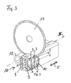
- the center slots 3 are arranged symmetrically in the embodiment of Fig. 1 to the central longitudinal axis III of the metal strip. As shown in Fig. 3, its length l 2 is chosen so large that the central slots 3 extend into the legs 9 of the U-profile 10 formed from the metal strip. The extension of the central slots 3 in the legs 9 of the U-profile 10 but only briefly in relation to their length l. 2
- the center slots 3 are not arranged symmetrically to the central longitudinal axis III of the metal strip, but to a longitudinal axis IV parallel thereto.
- the edge slots 1 have in this embodiment, on such a length l 1 , that overlap the edge slots with the center slots 3 only slightly in the transverse direction II of the metal strip. Accordingly, the edge slots 1 extending from the left edge in FIG. 2 to the strip interior have a shorter length than the edge slots 1 extending from the right edge to the strip interior in FIG. 2.
- the size of the overlap corresponds to that of the exemplary embodiment of FIG. 1.
- partitions 6 are provided only on the side of the long edge slots 1 of the metal strip, ie only starting from the right edge in Fig. 2.
- FIG. 3 shows the severing of a clamping profile equipped with a metal strip according to the invention.
- the metal strip is bent into a U-profile 10 and covered with a sealing material 11.
- the clamping profile has a sealing lip 12.
- a cutting disc 13 is used in the illustrated example, the drive is not shown.
- the cutting wheel can be automatically positioned at one of the center slots 3.
- a severing of the clamping profile at a point at which only short not severed areas, namely the areas 8 between the wedge tips 5 of the central slot 3 and the two opposite partitions 6 are present.
- These areas 8 have only a short length a of about 0.4 cm. It is Therefore, only a small input of energy required to sever the clamping profile, resulting in a slight deterioration of the clamping profile.
- 3 smooth cut surfaces can be obtained when severing the clamping profile in the region of a central slot.
Landscapes
- Engineering & Computer Science (AREA)
- Mechanical Engineering (AREA)
- Seal Device For Vehicle (AREA)
- Gasket Seals (AREA)
- Package Frames And Binding Bands (AREA)
- Clamps And Clips (AREA)
Abstract
Description
- Die vorliegende Erfindung betrifft ein Metallband als Einlage für Zier- oder Dichtstreifen aus flexiblem Material, insbesondere Gummi oder Kunststoff, welches insbesondere zu einem Profil gebogen wird, mit einer Vielzahl von insbesondere periodisch in Längsrichtung des Bandes aufeinanderfolgenden, von einem Rand des Metallbandes quer zu seiner Längsrichtung nach innen geführten, keilförmigen oder innen keilförmig auslaufenden Schlitzen und in Längsrichtung zwischen aufeinanderfolgenden Randschlitzen angeordneten, ebenfalls quer zur Längsrichtung des Metallbandes verlaufenden, aber nicht bis zum Rand geführten Mittelschlitzen, die zu ihren beiden Enden hin in einer Spitze auslaufen.
- Derartige Metallbänder werden insbesondere im Kraftfahrzeugbereich als Einlage für Dichtstreifen zum Abdichten von Motorraum-, Kofferraum- und Türöffnungen eingesetzt. Die kontinuierlich gefertigten Metallbänder sind mit Gummi und/oder flexiblem Kunststoff ummantelt und weisen Schlitze auf, unter anderem, um bei nicht haftmittelbeschichteten Metallbändern ein Durchdringen des Dichtmaterials zu ermöglichen, da die Haftung Gummi-Metall bzw. Kunststoff-Metall nicht möglich ist. Andererseits sind haftmittelbeschichtete Metallbänder sehr teuer. Vorteilhaft hergestellt werden können die Metallbänder durch rotatives Schneiden der Schlitze und anschließendes Walzstrecken des Metallbandes, nämlich abfalllos und mit hoher Fertigungsgeschwindigkeit.
- Die Metallbänder werden vor oder nach dem Ummanteln mit dem Dichtmaterial zu einem meist U-förmigen Klemmprofil gebogen, welches auf die Dichtflansche der Öffnung geklemmt wird. Um dabei den Konturen der Öffnung folgen zu können, muss das Klemmprofil meist sowohl in horizontaler als auch in vertikaler Ebene flexibel sein. Zudem soll das Klemmprofil in longitudinaler Richtung stauchbar sein, da die abzudichtenden Öffnungen erhebliche Umfangstoleranzen aufweisen können und ein Ablängen des Dichtstreifens vor Ort äußerst aufwändig wäre. Dichtstreifen mit stauchbarem Klemmprofil können nämlich auf die maximal vorkommende Länge bevorzugt endlos gefertigt und beim Einbau auf die tatsächliche Länge gestaucht werden. Ein Zusammenkleben, -vulkanisieren oder dergleichen dieser Dichtstreifen muss daher nicht vor Ort geschehen, so dass der Dichtstreifeneinbau auch von Robotern durchgeführt werden kann.
- Andererseits muss das Klemmprofil auch eine gewisse Zugfestigkeit aufweisen, da die Zier- oder Dichtleisten üblicherweise durch Extrudieren hergestellt werden, wobei erhebliche Kräfte in Längsrichtung des Bandes auftreten. Ein weiteres Erfordernis des Klemmprofils besteht darin, eine größtmögliche Klemmkraft auf die Dichtflansche auszuüben.
- Klemmprofile der genannten Art werden hergestellt, indem das Metallband kontinuierlich einem Extruder zugeführt wird, in welchem sich das Dichtmaterial unter Druckeinwirkung um das Metallband legt, welches anschließend aus dem Extruder durch eine Öffnung herausgedrückt wird, deren Form entsprechend dem gewünschten Profil des Dichtstreifens gewählt ist. Am Auslauf der Extrusionslinie muss das fertige Klemmprofil maßgenau abgelängt werden. Dies erfolgt durch Trennverfahren wie Sägen, Schleifen, mechanisches Schneiden, Laser- oder Plasmaschneiden. Dabei besteht die Schwierigkeit, dass ein verhältnismäßig schnell aus dem Extruder kontinuierlich austretendes Klemmprofil in einem diskontinuierlichen Arbeitsgang abgelängt werden muss. Die zur Verfügung stehende Zeit zum Durchtrennen ist daher sehr kurz. Zudem müssen gleichzeitig Materialien mit verschiedenen Eigenschaften durchtrennt werden, so dass ein hoher Energieeintrag erforderlich ist.
- Ein hoher Energieeintrag führt dazu, dass die das Metallband umgebenden Materialien wie Gummi, PVC und sonstige Dichtmassen beeinträchtigt werden und das Metallband zu stark freigelegt wird. Neben der optischen Abwertung des Produktes wird dadurch zum einen die Verletzungsgefahr erhöht und zum anderen das Zusammenvulkanisieren der beiden Enden des Dichtstreifens erschwert. Bei nicht oder schlecht vulkanisierten Dichtstreifen besteht die Gefahr, dass das Metallband korrodiert. Der Energieeintrag muss daher durch aufwändige Kühlung möglichst verringert werden.
- Der Erfindung liegt die Aufgabe zugrunde, ein Metallband der eingangs genannten Art anzugeben, welches diese Nachteile nicht aufweist. Insbesondere soll das Ablängen erleichtert und mit geringem Energieeintrag ermöglicht werden.
- Diese Aufgabe wird dadurch gelöst, dass das Metallband zusätzlich zu den Randschlitzen und den Mittelschlitzen quer zur Längsrichtung des Metallbandes verlaufende Durchtrennungen aufweist, die bei mindestens einem Teil der Mittelschlitze vorgesehen sind und von mindestens einem Rand des Metallbandes in Richtung auf die dem Rand gegenüberliegende Spitze des jeweiligen Mittelschlitzes verlaufen.
- Durch das Vorsehen von zusätzlichen Durchtrennungen des Metallbandes ergeben sich bei den betroffenen Mittelschlitzen verkürzte Schnittlängen.
- Der notwendige Energieeintrag zum Durchtrennen des Metallbandes an diesen Stellen ist daher verringert. Die Anordnung der zusätzlichen Durchtrennungen bei den Mittelschlitzen hat zudem den Vorteil, dass die bevorzugten Trennstellen leicht aufgefunden werden können. Bei einem automatisch durchgeführten Trennvorgang ist es daher möglich, diesen jeweils an den Stellen durchzuführen, an denen nur eine geringe Schnittlänge erforderlich ist. Ein weiterer Vorteil dieser Anordnung der zusätzlichen Durchtrennungen besteht darin, dass sich keine unfallträchtigen spitzen Endabschnitte beim Schneiden des Klemmprofils ergeben, sondern auf beiden Seiten eine gerade Schnittlinie entsteht.
- Bevorzugt sind die zusätzlichen Durchtrennungen bei jedem Mittelschlitz vorgesehen. Eine vorteilhafte Durchtrennung des Klemmprofils kann dadurch in kurzen Abständen erfolgen, so dass die gewünschte Länge des Klemmprofils besser eingehalten werden kann.
- Bevorzugt sind zusätzliche Durchtrennungen von beiden Rändern aus vorgesehen. Die verbleibende Schnittlänge kann dadurch weiter verringert werden.
- Um möglichst wenig Energie eintragen zu müssen, sind die zusätzlichen Durchtrennungen so vorgesehen, dass ein nur kurzer, nicht durchtrennter Bereich zwischen diesen und den Mittelschlitzen verbleibt. Die genannten Vorteile des erfindungsgemäßen Metallbandes können dadurch weiter vergrößert werden.
- Besonders bevorzugt weisen die nicht durchtrennten Bereiche zwischen den zusätzlichen Durchtrennungen und den gegenüberliegenden Spitzen der Mittelschlitze weniger als 0,5 cm auf. Mit derart kurzen nicht durchtrennten Bereichen konnten sehr gute Ergebnisse erzielt werden.
- Die Randschlitze sind insbesondere paarweise angeordnet, indem jeweils zwei Randschlitze einander gegenüberliegend von den beiden Rändern des Metallbandes nach innen geführt sind. Hierdurch ergibt sich ein flexibles Band mit hoher Klemmkraft.
- Nach einer Ausgestaltung der Erfindung sind die Mittelschlitze symmetrisch zur Mittellängsachse des Metallbandes angeordnet. Das Klemmprofil erhält dadurch eine in beiden horizontalen Richtungen gleiche Flexibilität.
- Bei symmetrisch zur Mittellängsachse des Metallbandes angeordneten Mittelschlitzen sind diese bevorzugt so lang ausgebildet, dass sie bei einem U-förmig gebogenen Profil bis in dessen Schenkel reichen. Die Flexibilität des Klemmprofils in den beiden horizontalen Richtungen weist dadurch eine vorteilhafte Größe auf.
- Die Erstreckung der Mittelschlitze in die Schenkel des U-Profils ist im Verhältnis zu ihrer Länge bevorzugt kurz. Damit ist eine hohe Klemmkraft des Profils sichergestellt.
- Nach einer anderen Ausgestaltung der Erfindung sind die Mittelschlitze symmetrisch zu einer zur Mittellängsachse des Metallbandes parallelen Achse angeordnet. Hierdurch ergibt sich ein Klemmprofil, welches in einer horizontalen Richtung eine höhere Flexibilität aufweist als in der anderen Richtung. Durch diese bevorzugte Biegbarkeit kann vorteilhafterweise ein fehlerhafter Einbau des Klemmprofils verhindert werden.
- Bei einer derart asymmetrischen Anordnung der Mittelschlitze sind diese bevorzugt so kurz ausgebildet, dass sie nur in einen Schenkel des U-Profils reichen. Zum einen wird dadurch die Klemmkraft erhöht und zum anderen ist der Unterschied in der Flexibilität in den beiden horizontalen Biegerichtungen groß und dadurch leicht feststellbar.
- Die Randschlitze und Mittelschlitze sind insbesondere in Querrichtung des Metallbandes überlappend ausgebildet. Hierdurch ergibt sich eine hohe Flexibilität und Stauchbarkeit des Klemmprofils.
- Bevorzugt überlappen sich die Randschlitze und die Mittelschlitze nur geringfügig. Eine zu hohe Flexibilität und damit eine zu geringe Zugfestigkeit kann dadurch verhindert werden.
- Die Herstellung der Randschlitze und der Mittelschlitze erfolgt bevorzugt durch Schneiden und anschließendes Aufweiten durch Walzstrecken. Damit können sehr hohe Fertigungsgeschwindigkeiten erreicht werden. Zudem ist die Herstellung abfalllos möglich, und die Öffnungsweite der Schlitze kann nach Bedarf variiert werden. Auch können Abmessungen wie Länge der Schlitze, Stegbreite, Zahnbreite und Bandbreite problemlos eingestellt werden.
- Die zusätzlichen Durchtrennungen sind bevorzugt nicht aufgeweitet. Da die zusätzlichen Durchtrennungen nur für den Trennvorgang benötigt werden, ist eine Aufweitung nicht erforderlich. Andererseits ist durch Unterlassen des Aufweitens der Durchtrennungen eine Erhöhung der Klemmkraft gegeben.
- Ausführungsbeispiele der Erfindung sind in den Zeichnungen dargestellt und werden nachfolgend beschrieben. Es zeigen, jeweils in schematischer Darstellung:
- Fig. 1
- eine erste Variante eines erfindungsgemäßen Metallbandes in Draufsicht,
- Fig. 2
- eine zweite Variante eines erfindungsgemäßen Metallbandes in Draufsicht, und
- Fig. 3
- eine perspektivische Ansicht eines Klemmprofils mit erfindungsgemäßem Metallband und Trennscheibe zum Durchtrennen des Profils.
- Das in Fig. 1 dargestellte Metallband, das als Einlage für Zier- oder Dichtstreifen aus flexiblem Material, insbesondere Gummi oder Kunststoff, verwendet werden kann, weist eine Vielzahl von periodisch in Längsrichtung I des Bandes aufeinanderfolgenden Randschlitzen 1 auf, die paarweise einander gegenüberliegend von den beiden Rändern 2 des Metallbandes nach innen geführt sind. Die Randschlitze 1 weisen eine Länge l1 auf, die etwa drei Achtel der Breite b des Metallbandes entspricht. Zwischen jeweils zwei aufeinanderfolgenden Paaren von Randschlitzen 1 weist das Metallband des weiteren jeweils einen Mittelschlitz 3 auf, dessen Länge l2 etwa die Hälfte der Bandbreite b beträgt. Dadurch überlappen die Mittelschlitze 3 in Querrichtung II des Metallbandes mit den Randschlitzen 1 geringfügig, nämlich um etwa ein Zwölftel der Breite b.
- Die Randschlitze 1 und die Mittelschlitze 3 sind durch Schneiden und Walzstrecken hergestellt und dadurch in Längsrichtung I des Metallbandes aufgeweitet. Die Randschlitze 1 weisen eine bandinnenseitig in einer Keilspitze 4 auslaufende Form auf, während die Mittelschlitze 3 zu den beiden Rändern des Metallbandes hin jeweils in einer Keilspitze 5 auslaufen.
- Zusätzlich zu den Randschlitzen 1 und den Mittelschlitzen 3 ist das Metallband mit quer zur Längsrichtung I des Metallbandes verlaufenden Durchtrennungen 6 versehen, die ebenfalls durch Schneiden hergestellt, aber nicht aufgeweitet sind und jeweils von einem Rand 2 des Metallbandes in Richtung auf die dem Rand 2 gegenüberliegende Keilspitze 5 eines Mittelschlitzes 3 verlaufen. Zwischen dem bandinnenseitigen Ende 7 der Durchtrennungen 6 und der jeweils gegenüberliegenden Keilspitze 5 der Mittelschlitze 3 befindet sich jeweils ein nur kurzer, nicht durchtrennter Bereich 8. Insbesondere weist dieser Bereich eine Erstreckung a in Querrichtung II des Metallbandes von weniger als 0,5 cm, im dargestellten Ausführungsbeispiel von ca. 0,4 cm auf.
- Die Mittelschlitze 3 sind bei dem Ausführungsbeispiel von Fig. 1 symmetrisch zur Mittellängsachse III des Metallbandes angeordnet. Wie in Fig. 3 dargestellt, ist ihre Länge l2 so groß gewählt, dass die Mittelschlitze 3 bis in die Schenkel 9 des aus dem Metallband gebildeten U-Profils 10 reichen. Die Erstreckung der Mittelschlitze 3 in die Schenkel 9 des U-Profils 10 ist aber nur kurz im Verhältnis zu ihrer Länge l2.
- Bei dem in Fig. 2 dargestellten Ausführungsbeispiel sind die Mittelschlitze 3 nicht symmetrisch zur Mittellängsachse III des Metallbandes, sondern zu einer hierzu parallelen Längsachse IV angeordnet. Die Randschlitze 1 weisen auch bei diesem Ausführungsbeispiel eine solche Länge l1 auf, dass sich die Randschlitze mit den Mittelschlitzen 3 nur geringfügig in Querrichtung II des Metallbandes überlappen. Dementsprechend weisen die sich vom in Fig. 2 linken Rand zum Bandinneren erstreckenden Randschlitze 1 eine geringere Länge auf als die sich vom in Fig. 2 rechten Rand zum Bandinneren erstreckenden Randschlitze 1. Die Größe der Überlappung entspricht derjenigen des Ausführungsbeispiels von Fig. 1.
- Des weiteren sind bei diesem Ausführungsbeispiel Durchtrennungen 6 nur auf der Seite der langen Randschlitze 1 des Metallbandes vorgesehen, also nur ausgehend vom rechten Rand in Fig. 2. Der nicht durchtrennte Bereich 8 zwischen den bandinnenseitigen Enden 7 und der jeweils gegenüberliegenden Keilspitze 5 der Mittelschlitze 3 weist auch hier eine nur kurze Länge a von bevorzugt weniger als 0,5 cm, insbesondere gemäß dem Ausführungsbeispiel von ca. 0,4 cm auf. Aufgrund der asymmetrischen Anordnung der Mittelschlitze 3 weist der Abstand der anderen Keilspitzen 5 der Mittelschlitze 3 vom linken Rand 2 des Metallbandes ebenfalls nur eine geringe Größe auf, insbesondere im dargestellten Ausführungsbeispiel von ca. 0,5 cm. Auch ohne Durchtrennungen auf der linken Seite des Metallbandes ergeben sich daher die geschilderten Vorteile beim Ablängen dieses Metallbandes. Es ist aber auch bei einer asymmetrischen Anordnung der Mittelschlitze 3 möglich, Durchtrennungen 6 auf beiden Seiten des Metallbandes, also ausgehend von beiden Rändern 2 vorzusehen.
- Fig. 3 zeigt das Durchtrennen eines mit einem erfindungsgemäßen Metallband ausgestatteten Klemmprofils. Das Metallband ist zu einem U-Profil 10 gebogen und mit einem Dichtmaterial 11 ummantelt. Außerdem weist das Klemmprofil eine Dichtlippe 12 auf.
- Zum Durchtrennen des Klemmprofils wird in dem dargestellten Beispiel eine Trennscheibe 13 verwendet, deren Antrieb nicht dargestellt ist. Die Trennscheibe kann automatisch bei einem der Mittelschlitze 3 positioniert werden. Dadurch kann eine Durchtrennung des Klemmprofils an einer Stelle erfolgen, an welcher nur kurze nicht durchtrennte Bereiche, nämlich die Bereiche 8 zwischen den Keilspitzen 5 des Mittelschlitzes 3 und den beiden gegenüberliegenden Durchtrennungen 6 vorhanden sind. Diese Bereiche 8 weisen eine nur kurze Länge a von ca. 0,4 cm auf. Es ist daher ein nur geringer Energieeintrag zum Durchtrennen des Klemmprofils erforderlich, wodurch sich eine geringe Beeinträchtigung des Klemmprofils ergibt. Zudem können beim Durchtrennen des Klemmprofils im Bereich eines Mittelschlitzes 3 glatte Schnittflächen erhalten werden.
-
- 1
- Randschlitz
- 2
- Rand
- 3
- Mittelschlitz
- 4
- Spitze von 1
- 5
- Spitze von 3
- 6
- Durchtrennung
- 7
- Ende von 6
- 8
- nicht durchtrennter Bereich
- 9
- Schenkel von 10
- 10
- U-Profil
- 11
- Ummantelung
- 12
- Dichtlippe
- 13
- Trennscheibe
- a
- Länge von 8
- b
- Breite des Metallbandes
- l1
- Länge von 1
- l2
- Länge von 3
- I
- Längsrichtung des Metallbandes
- II
- Querrichtung des Metallbandes
- III
- Mittellängsachse des Metallbandes
- IV
- Parallelachse zu III
Claims (10)
- Metallband als Einlage für Zier- oder Dichtstreifen aus flexiblem Material, insbesondere Gummi oder Kunststoff, welches insbesondere zu einem Profil (10) gebogen wird, mit einer Vielzahl von insbesondere periodisch in Längsrichtung (I) des Bandes aufeinanderfolgenden, von einem Rand (2) des Metallbandes quer zu seiner Längsrichtung (I) nach innen geführten, keilförmigen oder innen keilförmig auslaufenden Randschlitzen (1) und in Längsrichtung (I) zwischen aufeinanderfolgenden Randschlitzen (1) angeordneten, ebenfalls quer zur Längsrichtung (I) des Metallbandes verlaufenden, aber nicht bis zum Rand (2) geführten Mittelschlitzen (3), die zu ihren beiden Enden hin in einer Spitze (5) auslaufen,
dadurch gekennzeichnet,
dass das Metallband zusätzlich zu den Randschlitzen (1) und den Mittelschlitzen (3) quer zur Längsrichtung (I) des Metallbandes verlaufende Durchtrennungen (6) aufweist, die bei mindestens einem Teil der Mittelschlitze (3) vorgesehen sind und von mindestens einem Rand (2) des Metallbandes in Richtung auf die dem Rand (2) gegenüberliegende Spitze (5) des jeweiligen Mittelschlitzes (3) verlaufen. - Metallband nach Anspruch 1,
dadurch gekennzeichnet ,
dass bei jedem Mittelschlitz (3) Durchtrennungen (6) vorgesehen sind. - Metallband nach Anspruch 1 oder 2,
dadurch gekennzeichnet ,
dass Durchtrennungen (6) von beiden Rändern (2) ausgehend vorgesehen sind. - Metallband nach einem der vorhergehenden Ansprüche,
dadurch gekennzeichnet ,
dass zwischen dem inneren Ende (7) der Durchtrennungen (6) und der jeweils gegenüberliegenden Spitze (5) der Mittelschlitze (3) ein nur kurzer, nicht durchtrennter Bereich (8) vorhanden ist, wobei der nicht durchtrennte Bereich (8) bevorzugt eine Länge (a) von weniger als 0,5 cm aufweist, insbesondere ca. 0,4 cm. - Metallband nach einem der vorhergehenden Ansprüche,
dadurch gekennzeichnet,
dass die Randschlitze (1) paarweise angeordnet sind, indem jeweils zwei Randschlitze (1) einander gegenüberliegend von den beiden Rändern (2) des Metallbandes nach innen geführt sind. - Metallband nach einem der vorhergehenden Ansprüche,
dadurch gekennzeichnet ,
dass die Mittelschlitze (3) symmetrisch zur Mittellängsachse (III) des Metallbandes angeordnet sind, wobei die Mittelschlitze (3) bevorzugt eine solche Länge (l2) aufweisen, dass sie bei einem U-förmig gebogenen Profil (10) bis in dessen Schenkel (9) reichen, und wobei weiter bevorzugt die Mittelschlitze (3) nur ein im Verhältnis zu ihrer Länge (l2) kurzes Stück in die Schenkel (9) reichen. - Metallband nach einem der Ansprüche 1 bis 5,
dadurch gekennzeichnet ,
dass die Mittelschlitze (3) symmetrisch zu einer zur Mittellängsachse (III) des Metallbandes parallelen Achse (IV) angeordnet sind, wobei die Länge (l2) der Mittelschlitze (3) bevorzugt so kurz gewählt ist, dass die Mittelschlitze (3) nur in einen Schenkel (9) des Profils (10) reichen. - Metallband nach einem der vorhergehenden Ansprüche,
dadurch gekennzeichnet ,
dass die Randschlitze (1) und die Mittelschlitze (3) einander in Querrichtung (II) des Metallbandes überlappend ausgebildet sind, wobei die Randschlitze (1) und die Mittelschlitze (3) bevorzugt einander nur geringfügig überlappen. - Metallband nach einem der vorhergehenden Ansprüche,
dadurch gekennzeichnet ,
dass die Randschlitze (1) und die Mittelschlitze (3) geschnitten und durch Walzstrecken aufgeweitet sind. - Metallband nach einem der vorhergehenden Ansprüche,
dadurch gekennzeichnet ,
dass die Durchtrennungen (6) nicht aufgeweitet sind.
Priority Applications (1)
| Application Number | Priority Date | Filing Date | Title |
|---|---|---|---|
| PL06003293T PL1693237T5 (pl) | 2005-02-22 | 2006-02-17 | Taśma metalowa jako wkładka dla pasów ozdobnych lub uszczelniających |
Applications Claiming Priority (1)
| Application Number | Priority Date | Filing Date | Title |
|---|---|---|---|
| DE200520002832 DE202005002832U1 (de) | 2005-02-22 | 2005-02-22 | Metallband als Einlage für Zier- oder Dichtstreifen |
Publications (4)
| Publication Number | Publication Date |
|---|---|
| EP1693237A2 true EP1693237A2 (de) | 2006-08-23 |
| EP1693237A3 EP1693237A3 (de) | 2010-02-10 |
| EP1693237B1 EP1693237B1 (de) | 2013-09-25 |
| EP1693237B2 EP1693237B2 (de) | 2019-09-25 |
Family
ID=34609796
Family Applications (1)
| Application Number | Title | Priority Date | Filing Date |
|---|---|---|---|
| EP06003293.5A Active EP1693237B2 (de) | 2005-02-22 | 2006-02-17 | Metallband als Einlage für Zier- oder Dichtstreifen |
Country Status (4)
| Country | Link |
|---|---|
| US (1) | US7517590B2 (de) |
| EP (1) | EP1693237B2 (de) |
| DE (1) | DE202005002832U1 (de) |
| PL (1) | PL1693237T5 (de) |
Cited By (1)
| Publication number | Priority date | Publication date | Assignee | Title |
|---|---|---|---|---|
| WO2023031357A1 (de) * | 2021-09-02 | 2023-03-09 | Bfc Fahrzeugteile Gmbh | Metallband |
Families Citing this family (16)
| Publication number | Priority date | Publication date | Assignee | Title |
|---|---|---|---|---|
| US20090060656A1 (en) * | 2007-08-28 | 2009-03-05 | Allied Tube & Conduit Corporation | Paver edging device and method |
| US8205390B2 (en) * | 2009-02-26 | 2012-06-26 | Henniges Automotive Sealing Systems North America, Inc. | Mechanically stiffened weatherseal carrier |
| JP5556611B2 (ja) * | 2009-12-25 | 2014-07-23 | 豊田合成株式会社 | インサートの製造方法及びそのインサートを有する長尺成形品の製造方法 |
| US9073422B2 (en) | 2012-08-02 | 2015-07-07 | Fca Us Llc | Weatherstrip assembly and method of manufacturing the same |
| US9708816B2 (en) | 2014-05-30 | 2017-07-18 | Sacks Industrial Corporation | Stucco lath and method of manufacture |
| US9752323B2 (en) | 2015-07-29 | 2017-09-05 | Sacks Industrial Corporation | Light-weight metal stud and method of manufacture |
| DE102015120415B4 (de) * | 2015-11-25 | 2022-12-29 | Cqlt Saargummi Technologies S.À.R.L. | Verstärkungsprofil |
| DE102016114657A1 (de) | 2016-08-08 | 2018-02-08 | Rehau Ag + Co | Dichtungsprofil für ein Kraftfahrzeug oder Kraftfahrzeugbauteil sowie Verfahren zur Befestigung eines Dichtungsprofils |
| US9797142B1 (en) | 2016-09-09 | 2017-10-24 | Sacks Industrial Corporation | Lath device, assembly and method |
| DE102016125250B4 (de) | 2016-12-21 | 2021-10-07 | Webasto SE | Verfahren zur Herstellung von Dichtungen |
| US10760266B2 (en) | 2017-08-14 | 2020-09-01 | Clarkwestern Dietrich Building Systems Llc | Varied length metal studs |
| US11351593B2 (en) | 2018-09-14 | 2022-06-07 | Structa Wire Ulc | Expanded metal formed using rotary blades and rotary blades to form such |
| DE202019106738U1 (de) * | 2019-12-03 | 2021-03-04 | Bfc Fahrzeugteile Gmbh | Metallband |
| JP2022048510A (ja) * | 2020-09-15 | 2022-03-28 | 豊田合成株式会社 | ガラスラン |
| DE102023118748B3 (de) | 2023-07-14 | 2024-03-07 | STG Stanztechnik GmbH & Co. KG | Formkörper aus einer spritzfähigen Masse mit wenigstens einer Einlage |
| DE202023107375U1 (de) | 2023-07-14 | 2024-01-12 | STG Stanztechnik GmbH & Co. KG | Einlage für einen Formkörper aus einer spritzfähigen Masse sowie Formkörper |
Family Cites Families (10)
| Publication number | Priority date | Publication date | Assignee | Title |
|---|---|---|---|---|
| JPS60215447A (ja) † | 1984-04-11 | 1985-10-28 | Toyoda Gosei Co Ltd | トリム芯金 |
| GB8615680D0 (en) † | 1986-06-26 | 1986-07-30 | Silent Channel Prod Ltd | Carrier for strip structure |
| US4745665A (en) * | 1987-03-30 | 1988-05-24 | Hilsenbeck Henry K | Elongated clips having a metal core and metal core for such clips |
| GB2209045B (en) * | 1987-08-25 | 1991-06-05 | Silent Channel Prod Ltd | A core for a strip structure |
| DE4003622C2 (de) * | 1990-02-07 | 1995-05-24 | Bfc Buero Fahrzeugtech | Metallband als Einlage für Zier- und Dichtstreifen |
| US5199142A (en) * | 1991-09-04 | 1993-04-06 | The Gem City Engineering Co. | Production of expanded metal strip for reinforcing a resilient product |
| DE69501998T2 (de) * | 1994-10-20 | 1998-07-30 | Draftex Ind Ltd | Armierung für Dichtungsstreifen, Führungsleisten und Randleisten |
| US5783312A (en) * | 1996-12-19 | 1998-07-21 | The Gem City Engineering Co. | Expanded metal strip for reinforcing a resilient product |
| US6079160A (en) * | 1998-01-13 | 2000-06-27 | Arrowhead Industries Corporation | Core metal insert with stagger and offset backbone |
| US6447928B2 (en) * | 1998-10-01 | 2002-09-10 | Gem City Engineering Company | Process of manufacturing a core metal insert |
-
2005
- 2005-02-22 DE DE200520002832 patent/DE202005002832U1/de not_active Expired - Lifetime
- 2005-11-15 US US11/274,077 patent/US7517590B2/en active Active
-
2006
- 2006-02-17 EP EP06003293.5A patent/EP1693237B2/de active Active
- 2006-02-17 PL PL06003293T patent/PL1693237T5/pl unknown
Non-Patent Citations (1)
| Title |
|---|
| None |
Cited By (1)
| Publication number | Priority date | Publication date | Assignee | Title |
|---|---|---|---|---|
| WO2023031357A1 (de) * | 2021-09-02 | 2023-03-09 | Bfc Fahrzeugteile Gmbh | Metallband |
Also Published As
| Publication number | Publication date |
|---|---|
| DE202005002832U1 (de) | 2005-05-19 |
| PL1693237T5 (pl) | 2020-07-27 |
| EP1693237B1 (de) | 2013-09-25 |
| EP1693237A3 (de) | 2010-02-10 |
| US20060185132A1 (en) | 2006-08-24 |
| US7517590B2 (en) | 2009-04-14 |
| EP1693237B2 (de) | 2019-09-25 |
| PL1693237T3 (pl) | 2014-03-31 |
Similar Documents
| Publication | Publication Date | Title |
|---|---|---|
| EP1693237B1 (de) | Metallband als Einlage für Zier- oder Dichtstreifen | |
| DE69501998T2 (de) | Armierung für Dichtungsstreifen, Führungsleisten und Randleisten | |
| DE2937454C2 (de) | Verbundprofil, insbesondere für Fenster, Türen und Fassaden sowie Verfahren zum Herstellen des Verbundprofils | |
| DE3814448C2 (de) | ||
| EP1666295B1 (de) | Metallband als Einlage für Zier- oder Dichtstreifen | |
| EP0290536B2 (de) | Verfahren zur herstellung eines fensterprofiles mit einem dichtungselement | |
| DE69005987T2 (de) | Dichtung, Vorrichtung und Verfahren zur ihrer Herstellung. | |
| DE2302877C3 (de) | Verfahren zum Herstellen von Metalleinlagen für profilierte und flexible Bänder mit einer Umhüllung | |
| WO2021110428A1 (de) | Metallband | |
| DE2444859A1 (de) | Verfahren und vorrichtung zur herstellung von streckmetall-gitterplatten fuer blei-saeure-akkumulatoren | |
| DE2226824A1 (de) | Vorrichtung zum formen steifer, bandverstaerkter verbundstoffteile | |
| DE10124484C1 (de) | Verfahren und Vorrichtung zum Einbringen eines in Längsrichtung wechselnden Schnitt- bzw. Stanzbildes in ein metallisches Trägerband für Karosseriedichtungen, sowie danach hergestellte Trägerbänder für Karosseriedichtungen | |
| EP3380351B1 (de) | Verstärkungsprofil | |
| EP0441287B1 (de) | Metallband als Einlage für Zier- und Dichtstreife | |
| DE69106593T2 (de) | Metallische Armierung für Dichtungsband oder dergleichen und Verfahren zu seiner Herstellung. | |
| DE4101187C1 (de) | ||
| DE3543767A1 (de) | Verfahren und vorrichtung zur kontinuierlichen herstellung von mit kunststoff ausgeschaeumten profilen | |
| WO2016202534A1 (de) | Verfahren zum herstellen eines kunststoffantriebskabels, kunststoffantriebskabel und formzahnrad | |
| DE4030922C2 (de) | Klemmprofilanordnung | |
| DE2342191A1 (de) | Vorrichtung zur fortlaufenden ausbildung einer isolierten platte | |
| EP1464526B1 (de) | Metallband als Einlage für Zier- oder Dichtstreifen | |
| EP0621119B1 (de) | Verfahren zur Herstellung von endlichen Profilsträngen | |
| EP2631091A1 (de) | Laufstreifenprofil eines Fahrzeugreifens | |
| DE1933816C3 (de) | Vulkanisierform für Fahrzeugreifen | |
| WO2013185968A1 (de) | Verfahren zum herstellen einer wischleiste sowie eine hergestellte wischleiste |
Legal Events
| Date | Code | Title | Description |
|---|---|---|---|
| PUAI | Public reference made under article 153(3) epc to a published international application that has entered the european phase |
Free format text: ORIGINAL CODE: 0009012 |
|
| AK | Designated contracting states |
Kind code of ref document: A2 Designated state(s): AT BE BG CH CY CZ DE DK EE ES FI FR GB GR HU IE IS IT LI LT LU LV MC NL PL PT RO SE SI SK TR |
|
| AX | Request for extension of the european patent |
Extension state: AL BA HR MK YU |
|
| RAP1 | Party data changed (applicant data changed or rights of an application transferred) |
Owner name: BFC BUERO- UND FAHRZEUGTECHNIK GMBH & CO. PROD. KG |
|
| PUAL | Search report despatched |
Free format text: ORIGINAL CODE: 0009013 |
|
| AK | Designated contracting states |
Kind code of ref document: A3 Designated state(s): AT BE BG CH CY CZ DE DK EE ES FI FR GB GR HU IE IS IT LI LT LU LV MC NL PL PT RO SE SI SK TR |
|
| AX | Request for extension of the european patent |
Extension state: AL BA HR MK YU |
|
| 17P | Request for examination filed |
Effective date: 20100809 |
|
| 17Q | First examination report despatched |
Effective date: 20100907 |
|
| AKX | Designation fees paid |
Designated state(s): AT BE BG CH CY CZ DE DK EE ES FI FR GB GR HU IE IS IT LI LT LU LV MC NL PL PT RO SE SI SK TR |
|
| RAP1 | Party data changed (applicant data changed or rights of an application transferred) |
Owner name: BFC FAHRZEUGTEILE GMBH |
|
| GRAP | Despatch of communication of intention to grant a patent |
Free format text: ORIGINAL CODE: EPIDOSNIGR1 |
|
| INTG | Intention to grant announced |
Effective date: 20130412 |
|
| GRAS | Grant fee paid |
Free format text: ORIGINAL CODE: EPIDOSNIGR3 |
|
| GRAA | (expected) grant |
Free format text: ORIGINAL CODE: 0009210 |
|
| AK | Designated contracting states |
Kind code of ref document: B1 Designated state(s): AT BE BG CH CY CZ DE DK EE ES FI FR GB GR HU IE IS IT LI LT LU LV MC NL PL PT RO SE SI SK TR |
|
| REG | Reference to a national code |
Ref country code: GB Ref legal event code: FG4D Free format text: NOT ENGLISH |
|
| REG | Reference to a national code |
Ref country code: CH Ref legal event code: EP |
|
| REG | Reference to a national code |
Ref country code: AT Ref legal event code: REF Ref document number: 633562 Country of ref document: AT Kind code of ref document: T Effective date: 20131015 |
|
| REG | Reference to a national code |
Ref country code: IE Ref legal event code: FG4D Free format text: LANGUAGE OF EP DOCUMENT: GERMAN |
|
| REG | Reference to a national code |
Ref country code: DE Ref legal event code: R096 Ref document number: 502006013224 Country of ref document: DE Effective date: 20131121 |
|
| PG25 | Lapsed in a contracting state [announced via postgrant information from national office to epo] |
Ref country code: SE Free format text: LAPSE BECAUSE OF FAILURE TO SUBMIT A TRANSLATION OF THE DESCRIPTION OR TO PAY THE FEE WITHIN THE PRESCRIBED TIME-LIMIT Effective date: 20130925 Ref country code: LT Free format text: LAPSE BECAUSE OF FAILURE TO SUBMIT A TRANSLATION OF THE DESCRIPTION OR TO PAY THE FEE WITHIN THE PRESCRIBED TIME-LIMIT Effective date: 20130925 |
|
| REG | Reference to a national code |
Ref country code: NL Ref legal event code: VDEP Effective date: 20130925 |
|
| REG | Reference to a national code |
Ref country code: LT Ref legal event code: MG4D |
|
| PG25 | Lapsed in a contracting state [announced via postgrant information from national office to epo] |
Ref country code: SI Free format text: LAPSE BECAUSE OF FAILURE TO SUBMIT A TRANSLATION OF THE DESCRIPTION OR TO PAY THE FEE WITHIN THE PRESCRIBED TIME-LIMIT Effective date: 20130925 Ref country code: FI Free format text: LAPSE BECAUSE OF FAILURE TO SUBMIT A TRANSLATION OF THE DESCRIPTION OR TO PAY THE FEE WITHIN THE PRESCRIBED TIME-LIMIT Effective date: 20130925 Ref country code: GR Free format text: LAPSE BECAUSE OF FAILURE TO SUBMIT A TRANSLATION OF THE DESCRIPTION OR TO PAY THE FEE WITHIN THE PRESCRIBED TIME-LIMIT Effective date: 20131226 Ref country code: LV Free format text: LAPSE BECAUSE OF FAILURE TO SUBMIT A TRANSLATION OF THE DESCRIPTION OR TO PAY THE FEE WITHIN THE PRESCRIBED TIME-LIMIT Effective date: 20130925 |
|
| PG25 | Lapsed in a contracting state [announced via postgrant information from national office to epo] |
Ref country code: EE Free format text: LAPSE BECAUSE OF FAILURE TO SUBMIT A TRANSLATION OF THE DESCRIPTION OR TO PAY THE FEE WITHIN THE PRESCRIBED TIME-LIMIT Effective date: 20130925 Ref country code: NL Free format text: LAPSE BECAUSE OF FAILURE TO SUBMIT A TRANSLATION OF THE DESCRIPTION OR TO PAY THE FEE WITHIN THE PRESCRIBED TIME-LIMIT Effective date: 20130925 Ref country code: SK Free format text: LAPSE BECAUSE OF FAILURE TO SUBMIT A TRANSLATION OF THE DESCRIPTION OR TO PAY THE FEE WITHIN THE PRESCRIBED TIME-LIMIT Effective date: 20130925 Ref country code: IS Free format text: LAPSE BECAUSE OF FAILURE TO SUBMIT A TRANSLATION OF THE DESCRIPTION OR TO PAY THE FEE WITHIN THE PRESCRIBED TIME-LIMIT Effective date: 20140125 Ref country code: RO Free format text: LAPSE BECAUSE OF FAILURE TO SUBMIT A TRANSLATION OF THE DESCRIPTION OR TO PAY THE FEE WITHIN THE PRESCRIBED TIME-LIMIT Effective date: 20130925 Ref country code: CZ Free format text: LAPSE BECAUSE OF FAILURE TO SUBMIT A TRANSLATION OF THE DESCRIPTION OR TO PAY THE FEE WITHIN THE PRESCRIBED TIME-LIMIT Effective date: 20130925 |
|
| PG25 | Lapsed in a contracting state [announced via postgrant information from national office to epo] |
Ref country code: CY Free format text: LAPSE BECAUSE OF FAILURE TO SUBMIT A TRANSLATION OF THE DESCRIPTION OR TO PAY THE FEE WITHIN THE PRESCRIBED TIME-LIMIT Effective date: 20130925 Ref country code: ES Free format text: LAPSE BECAUSE OF FAILURE TO SUBMIT A TRANSLATION OF THE DESCRIPTION OR TO PAY THE FEE WITHIN THE PRESCRIBED TIME-LIMIT Effective date: 20130925 |
|
| REG | Reference to a national code |
Ref country code: DE Ref legal event code: R026 Ref document number: 502006013224 Country of ref document: DE |
|
| PG25 | Lapsed in a contracting state [announced via postgrant information from national office to epo] |
Ref country code: PT Free format text: LAPSE BECAUSE OF FAILURE TO SUBMIT A TRANSLATION OF THE DESCRIPTION OR TO PAY THE FEE WITHIN THE PRESCRIBED TIME-LIMIT Effective date: 20140127 |
|
| PLBI | Opposition filed |
Free format text: ORIGINAL CODE: 0009260 |
|
| PLAX | Notice of opposition and request to file observation + time limit sent |
Free format text: ORIGINAL CODE: EPIDOSNOBS2 |
|
| 26 | Opposition filed |
Opponent name: STG STANZTECHNIK GMBH & CO.KG Effective date: 20140625 |
|
| PG25 | Lapsed in a contracting state [announced via postgrant information from national office to epo] |
Ref country code: IT Free format text: LAPSE BECAUSE OF FAILURE TO SUBMIT A TRANSLATION OF THE DESCRIPTION OR TO PAY THE FEE WITHIN THE PRESCRIBED TIME-LIMIT Effective date: 20130925 |
|
| BERE | Be: lapsed |
Owner name: BFC FAHRZEUGTEILE G.M.B.H. Effective date: 20140228 |
|
| REG | Reference to a national code |
Ref country code: DE Ref legal event code: R026 Ref document number: 502006013224 Country of ref document: DE Effective date: 20140625 |
|
| PG25 | Lapsed in a contracting state [announced via postgrant information from national office to epo] |
Ref country code: DK Free format text: LAPSE BECAUSE OF FAILURE TO SUBMIT A TRANSLATION OF THE DESCRIPTION OR TO PAY THE FEE WITHIN THE PRESCRIBED TIME-LIMIT Effective date: 20130925 Ref country code: LU Free format text: LAPSE BECAUSE OF FAILURE TO SUBMIT A TRANSLATION OF THE DESCRIPTION OR TO PAY THE FEE WITHIN THE PRESCRIBED TIME-LIMIT Effective date: 20140217 Ref country code: MC Free format text: LAPSE BECAUSE OF FAILURE TO SUBMIT A TRANSLATION OF THE DESCRIPTION OR TO PAY THE FEE WITHIN THE PRESCRIBED TIME-LIMIT Effective date: 20130925 |
|
| REG | Reference to a national code |
Ref country code: CH Ref legal event code: PL |
|
| GBPC | Gb: european patent ceased through non-payment of renewal fee |
Effective date: 20140217 |
|
| PG25 | Lapsed in a contracting state [announced via postgrant information from national office to epo] |
Ref country code: CH Free format text: LAPSE BECAUSE OF NON-PAYMENT OF DUE FEES Effective date: 20140228 Ref country code: LI Free format text: LAPSE BECAUSE OF NON-PAYMENT OF DUE FEES Effective date: 20140228 |
|
| REG | Reference to a national code |
Ref country code: IE Ref legal event code: MM4A |
|
| PLAF | Information modified related to communication of a notice of opposition and request to file observations + time limit |
Free format text: ORIGINAL CODE: EPIDOSCOBS2 |
|
| PG25 | Lapsed in a contracting state [announced via postgrant information from national office to epo] |
Ref country code: GB Free format text: LAPSE BECAUSE OF NON-PAYMENT OF DUE FEES Effective date: 20140217 Ref country code: BE Free format text: LAPSE BECAUSE OF NON-PAYMENT OF DUE FEES Effective date: 20140228 Ref country code: IE Free format text: LAPSE BECAUSE OF NON-PAYMENT OF DUE FEES Effective date: 20140217 |
|
| PLBB | Reply of patent proprietor to notice(s) of opposition received |
Free format text: ORIGINAL CODE: EPIDOSNOBS3 |
|
| REG | Reference to a national code |
Ref country code: AT Ref legal event code: MM01 Ref document number: 633562 Country of ref document: AT Kind code of ref document: T Effective date: 20140217 |
|
| PG25 | Lapsed in a contracting state [announced via postgrant information from national office to epo] |
Ref country code: AT Free format text: LAPSE BECAUSE OF NON-PAYMENT OF DUE FEES Effective date: 20140217 |
|
| REG | Reference to a national code |
Ref country code: FR Ref legal event code: PLFP Year of fee payment: 11 |
|
| PG25 | Lapsed in a contracting state [announced via postgrant information from national office to epo] |
Ref country code: BG Free format text: LAPSE BECAUSE OF FAILURE TO SUBMIT A TRANSLATION OF THE DESCRIPTION OR TO PAY THE FEE WITHIN THE PRESCRIBED TIME-LIMIT Effective date: 20130925 |
|
| RIC2 | Information provided on ipc code assigned after grant |
Ipc: B60J 10/18 20160101AFI20160615BHEP |
|
| PG25 | Lapsed in a contracting state [announced via postgrant information from national office to epo] |
Ref country code: HU Free format text: LAPSE BECAUSE OF FAILURE TO SUBMIT A TRANSLATION OF THE DESCRIPTION OR TO PAY THE FEE WITHIN THE PRESCRIBED TIME-LIMIT; INVALID AB INITIO Effective date: 20060217 |
|
| APBM | Appeal reference recorded |
Free format text: ORIGINAL CODE: EPIDOSNREFNO |
|
| APBP | Date of receipt of notice of appeal recorded |
Free format text: ORIGINAL CODE: EPIDOSNNOA2O |
|
| APAH | Appeal reference modified |
Free format text: ORIGINAL CODE: EPIDOSCREFNO |
|
| APBQ | Date of receipt of statement of grounds of appeal recorded |
Free format text: ORIGINAL CODE: EPIDOSNNOA3O |
|
| REG | Reference to a national code |
Ref country code: FR Ref legal event code: PLFP Year of fee payment: 12 |
|
| REG | Reference to a national code |
Ref country code: FR Ref legal event code: PLFP Year of fee payment: 13 |
|
| APBU | Appeal procedure closed |
Free format text: ORIGINAL CODE: EPIDOSNNOA9O |
|
| RIC2 | Information provided on ipc code assigned after grant |
Ipc: B60R 13/06 20060101ALI20190502BHEP Ipc: F16B 5/12 20060101ALI20190502BHEP Ipc: B60J 10/18 20160101AFI20190502BHEP Ipc: B60R 13/04 20060101ALI20190502BHEP |
|
| PUAH | Patent maintained in amended form |
Free format text: ORIGINAL CODE: 0009272 |
|
| STAA | Information on the status of an ep patent application or granted ep patent |
Free format text: STATUS: PATENT MAINTAINED AS AMENDED |
|
| 27A | Patent maintained in amended form |
Effective date: 20190925 |
|
| AK | Designated contracting states |
Kind code of ref document: B2 Designated state(s): AT BE BG CH CY CZ DE DK EE ES FI FR GB GR HU IE IS IT LI LT LU LV MC NL PL PT RO SE SI SK TR |
|
| REG | Reference to a national code |
Ref country code: DE Ref legal event code: R102 Ref document number: 502006013224 Country of ref document: DE |
|
| PGFP | Annual fee paid to national office [announced via postgrant information from national office to epo] |
Ref country code: TR Payment date: 20240210 Year of fee payment: 19 Ref country code: PL Payment date: 20240208 Year of fee payment: 19 Ref country code: FR Payment date: 20240220 Year of fee payment: 19 |
|
| PGFP | Annual fee paid to national office [announced via postgrant information from national office to epo] |
Ref country code: DE Payment date: 20240426 Year of fee payment: 19 |