EP1693173B1 - Steuerverfahren einer steuerbaren Wandsäge - Google Patents
Steuerverfahren einer steuerbaren Wandsäge Download PDFInfo
- Publication number
- EP1693173B1 EP1693173B1 EP20060101001 EP06101001A EP1693173B1 EP 1693173 B1 EP1693173 B1 EP 1693173B1 EP 20060101001 EP20060101001 EP 20060101001 EP 06101001 A EP06101001 A EP 06101001A EP 1693173 B1 EP1693173 B1 EP 1693173B1
- Authority
- EP
- European Patent Office
- Prior art keywords
- saw
- wall
- reversal point
- module
- program
- Prior art date
- Legal status (The legal status is an assumption and is not a legal conclusion. Google has not performed a legal analysis and makes no representation as to the accuracy of the status listed.)
- Expired - Lifetime
Links
Images

Classifications
-
- B—PERFORMING OPERATIONS; TRANSPORTING
- B28—WORKING CEMENT, CLAY, OR STONE
- B28D—WORKING STONE OR STONE-LIKE MATERIALS
- B28D1/00—Working stone or stone-like materials, e.g. brick, concrete or glass, not provided for elsewhere; Machines, devices, tools therefor
- B28D1/02—Working stone or stone-like materials, e.g. brick, concrete or glass, not provided for elsewhere; Machines, devices, tools therefor by sawing
- B28D1/04—Working stone or stone-like materials, e.g. brick, concrete or glass, not provided for elsewhere; Machines, devices, tools therefor by sawing with circular or cylindrical saw-blades or saw-discs
- B28D1/045—Sawing grooves in walls; sawing stones from rocks; sawing machines movable on the stones to be cut
-
- B—PERFORMING OPERATIONS; TRANSPORTING
- B23—MACHINE TOOLS; METAL-WORKING NOT OTHERWISE PROVIDED FOR
- B23D—PLANING; SLOTTING; SHEARING; BROACHING; SAWING; FILING; SCRAPING; LIKE OPERATIONS FOR WORKING METAL BY REMOVING MATERIAL, NOT OTHERWISE PROVIDED FOR
- B23D59/00—Accessories specially designed for sawing machines or sawing devices
- B23D59/001—Measuring or control devices, e.g. for automatic control of work feed pressure on band saw blade
- B23D59/002—Measuring or control devices, e.g. for automatic control of work feed pressure on band saw blade for the position of the saw blade
-
- B—PERFORMING OPERATIONS; TRANSPORTING
- B23—MACHINE TOOLS; METAL-WORKING NOT OTHERWISE PROVIDED FOR
- B23D—PLANING; SLOTTING; SHEARING; BROACHING; SAWING; FILING; SCRAPING; LIKE OPERATIONS FOR WORKING METAL BY REMOVING MATERIAL, NOT OTHERWISE PROVIDED FOR
- B23D59/00—Accessories specially designed for sawing machines or sawing devices
- B23D59/008—Accessories specially designed for sawing machines or sawing devices comprising computers
-
- B—PERFORMING OPERATIONS; TRANSPORTING
- B28—WORKING CEMENT, CLAY, OR STONE
- B28D—WORKING STONE OR STONE-LIKE MATERIALS
- B28D7/00—Accessories specially adapted for use with machines or devices of the preceding groups
- B28D7/005—Devices for the automatic drive or the program control of the machines
Definitions
- the invention relates to a control method according to the preamble of claim 1 and a computer program product according to claim 8.
- Wall saws fixed to the wall to be separated with a disc-shaped saw blade for processing stone are used in construction, for example for the separation of walls, to create an opening in the wall by means of several staggered cuts.
- the wall itself is limited by side walls, under wall and floor and ceiling is to be understood.
- the arranged in the sliding saw head rotary drive of the saw blade is done via high-performance hydraulic motors or electric motors, which are each connected via flexible lines with corresponding separate supply units.
- a wall saw has a saw head slidable along a guide rail with a rotary drive and a pivotally adjustable saw arm, at the radial end of which the rotationally driven disc-shaped saw blade is detachably mounted, wherein the guide rail itself is fastened to the wall to be separated.
- a wall saw to which this invention is limited, has the user controllable degrees of freedom of rotation of the saw blade, the Winkelverschwenkung the saw arm and the longitudinal displacement of the saw head.
- the cutting diameter can be changed as a parameter manually by changing the disc-shaped saw blade.
- an at least piecewise automated sawing process is not achieved.
- DE19737617 has a directly attached to the wall to be separated, controllable wall saw control electronics and a portable remote control, with which the rotary drive and the feed of the user are manually remotely controlled.
- the hydraulic drive can be controlled electrically via program-controlled hydraulic valves with stepper motors and limit switches.
- stepper motors and limit switches can be controlled electrically via program-controlled hydraulic valves with stepper motors and limit switches.
- an at least piece-by-piece automated sawing process is not achieved, but the direct control is done manually by the user with the remote control, which actively pursues the sawing process itself.
- stationary program-controlled stone processing machines for the fully automatic separation of compact rock stones are known, for example, according to the DE4006668 in which the rockstone to be separated is positioned on a workbench in the working area of a saw blade which is displaceable along longitudinal guide rails with displacement sensors in several dimensions.
- the saw blade travels back and forth repeatedly with a depth offset, whereby the optimal reversing points after the DE4003347 be calculated from the contour of the rock stone determined by distance sensors.
- Such control methods are not suitable for directly on the wall to be separated wall saws.
- no obstacles in the form of, for example, sidewalls must be taken into account when separating rocks.
- the object of the invention is to realize a control method for an at least piecewise automated sawing process of a wall saw.
- the program control means By the program control means, the displacement sensor and the swivel angle sensor, the controllable wall saw in the sawing process in addition to a manual control and at least piecewise automated controlled by a program.
- the user is thereby released from his direct tax task and can increasingly devote himself to the control of the at least piecewise automated sawing process.
- the output means is a graphical display, whereby the sawing process can be graphically simulated and tracked on site.
- Both the execution and the return direction is a pulling direction which forms an obtuse angle with the saw arm, thereby sawing in the more stable pulling direction.
- the direction of rotation of the saw blade is oriented such that in the wall, the tangential cutting direction is oriented to the pulling direction, whereby along the saw arm adjusts a tensile stress, which contributes to a stable guidance of the saw blade and thus to a clean, narrow section leads.
- a further first step is inserted between the second and the third step, whereby the reverse direction also contributes to the saw progress, whereby the sawing speed is increased.
- the saw arm is pivoted beforehand, whereby both the execution and the return direction in the pulling direction. After swiveling, the saw blade will be up to the nearest one Advancing point advanced in the pressure direction, whereby an exact cut start is achieved.
- an end depth can be entered via the input means, after which processing is returned to the initial state by the sawing process which is completely program-controlled by the program control means, whereby the automated sawing process is ended.
- At least one inflection point as a one-sided obstacle, the exceeding of which is interpreted as an impermissible area in the sawing process that is completely program-controlled by the program control means, which ensures programmatically that the saw blade and / or the saw head does not touch the obstacle during any movement becomes.
- the user is asked to change the saw blade to another saw blade diameter, while advantageously calculating and outputting its optimum value, thereby enabling deep cuts between two side walls ,
- a turning point not defined as an obstacle is changeable by the program control means
- Overcut turning point definable which allows an overcut on the machine side wall side, which can be calculated by the program control means via a function of the current cutting depth and the saw blade diameter, for example via a simple circular function.
- the cut ends with the final cutting depth then exactly at the desired end, ie at this overcut turning point, in particular at the, the machine side wall side opposite, hidden wall side.
- an inflection point as an obstacle is also possible if there is no physical obstacle at all, whereby the user can achieve that after each swiveling of the saw arm, the cut is terminated in the print mode, resulting in a cleaner cut end.
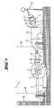
- a controllable wall saw 1 has a saw head 3, which is displaceable along a guide rail 2, and a pivotably adjustable saw arm 4, at the radial end of which a rotationally driven disk-shaped saw blade 5 is detachably mounted.
- the guide rail 2 itself is attached via anchor 6 directly to a wall 7 to be separated, which is bounded by a vertical auxiliary wall 18 thereto.
- the arranged in the movable saw head 3 rotary drive 8 of the saw blade 5 is effected via a high-performance electric motor, which is connected via flexible lines 9 with a separate, portable supply unit 10, which in turn is connected to a remote control 11, which operates a user 12.
- the saw head 3, the rotary drive 8 and the saw arm 4 controlling program control means 13 in the form of a microcontroller with input means 14 in the form of keys and output means 15 in the form of a graphical display available.
- the program control means 13 is also connected to a displacement sensor 16 for determining the position of the saw head 3 along the guide rail 2 and with a swivel angle sensor 17 for determining the swivel angle a of the saw arm 4 to the longitudinal direction of the guide rail 2.
- the saw blade 5 with a saw blade diameter d works in the sawing process between the two Turning points W repeated back and forth movements with an incremental depth of cut S up to a final depth T in the wall 7.
- the saw blade 5, mediated via the saw head 3 and the saw arm 4, in the pulling direction Z or in the printing direction D along the guide rail 2 slidably.
- the fixing of the guide rail directly to the wall to be sawn and the positioning of the saw blade at an initial position takes place preparatory in manual preparation process, not shown.
- the input means via the input means, the input of the saw blade diameter, two inflection points and their random definition as obstacle or overcut turning point, the final depth, the sawing mode (sawing only in the pulling direction or in tension / compression direction) and other parameters such as wall material and armor strength.
- the program control means the determination of the speed, the feed rate and the incremental depth of cut suitable.
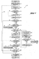
- the algorithm 19 of the sawing process consisting of individual modules (#), after the start of a suitable initial state (FIG. Fig.
- the saw arm is pivoted in the direction of the wall by the incremental cutting depth ( Fig. 3b ) in a second step in the module (5) the saw head along the guide rail in a, at an obtuse angle with the saw arm forming, pulling direction to the first inflection point at the feed rate advanced ( Fig. 3c ), and in a third step in the module (11) the saw head is moved back along the guide rail in the direction opposite to the direction of the pressure direction to the second inflection point ( Fig.
- a directed step sequence comprising the first step in the module (2), the second step in the module (5) and the third step in the module (11) is repeated several times.
- the direction of rotation of the saw blade is oriented such that in the wall, the tangential cutting direction is oriented to the pulling direction ( Fig. 1 ).
- the second step in the module (5) or in the module (20) and the third step in the module (11) or in the module (19) is for additional pivoting to the incremental depth of cut a the first step in the module (2) corresponding , further step in the module (10) or in the module (17) inserted.
- To Fig. 3a to Fig. 3k is a completely program controlled by the program control sawing process between two side walls 18 shown.
- the side walls 18 were entered in the preparation process as inflection points W and defined as obstacles.
- To Fig. 3a the saw head 3 is moved with lifted off the wall 3 saw blade 5 to an initial state.
- To Fig. 3b is then moved by pivoting the saw arm 4, the saw blade 5 in the wall 7 into it.
- To Fig. 3d is then reset upon approach of the saw head 3 to the near side wall 18 of the saw head 3.
- the saw arm 4 is recirculated over the wall-free half-space to the near side wall 18.
- the remaining distance of the saw blade 5 is sawed to the side wall 18 in the printing direction D.
- the saw head 3 is advanced in the pulling direction Z.
- To Fig. 3h is then reset upon approach of the saw head 3 to the near side wall 18 of the saw head 3.
- the saw arm 4 is recirculated over the wall-free half-space to the near side wall 18, and the saw blade 5 is moved deeper into the wall 7.
Landscapes
- Engineering & Computer Science (AREA)
- Mechanical Engineering (AREA)
- Mining & Mineral Resources (AREA)
- Processing Of Stones Or Stones Resemblance Materials (AREA)
Applications Claiming Priority (1)
| Application Number | Priority Date | Filing Date | Title |
|---|---|---|---|
| DE200510000013 DE102005000013A1 (de) | 2005-02-22 | 2005-02-22 | Steuerbare Wandsäge und Steuerverfahren |
Publications (2)
| Publication Number | Publication Date |
|---|---|
| EP1693173A1 EP1693173A1 (de) | 2006-08-23 |
| EP1693173B1 true EP1693173B1 (de) | 2013-11-27 |
Family
ID=36295435
Family Applications (1)
| Application Number | Title | Priority Date | Filing Date |
|---|---|---|---|
| EP20060101001 Expired - Lifetime EP1693173B1 (de) | 2005-02-22 | 2006-01-30 | Steuerverfahren einer steuerbaren Wandsäge |
Country Status (5)
| Country | Link |
|---|---|
| US (1) | US7337037B2 (https=) |
| EP (1) | EP1693173B1 (https=) |
| JP (1) | JP5201796B2 (https=) |
| DE (1) | DE102005000013A1 (https=) |
| ES (1) | ES2440781T3 (https=) |
Cited By (7)
| Publication number | Priority date | Publication date | Assignee | Title |
|---|---|---|---|---|
| EP2993009A1 (de) | 2014-09-08 | 2016-03-09 | HILTI Aktiengesellschaft | Verfahren zur Steuerung eines Wandsägesystems beim Erstellen eines Trennschnittes |
| EP2993014A1 (de) | 2014-09-08 | 2016-03-09 | HILTI Aktiengesellschaft | Verfahren zur Steuerung eines Wandsägesystems beim Erstellen eines Trennschnittes |
| EP2993015A1 (de) | 2014-09-08 | 2016-03-09 | HILTI Aktiengesellschaft | Verfahren zur Steuerung eines Wandsägesystems beim Erstellen eines Trennschnittes |
| EP2993013A1 (de) | 2014-09-08 | 2016-03-09 | Hilti Aktiengesellschaft | Verfahren zur Steuerung eines Wandsägesystems beim Erstellen eines Trennschnittes |
| EP2993012A1 (de) | 2014-09-08 | 2016-03-09 | HILTI Aktiengesellschaft | Verfahren zur Steuerung eines Wandsägesystems beim Erstellen eines Trennschnittes |
| EP2993011A1 (de) | 2014-09-08 | 2016-03-09 | HILTI Aktiengesellschaft | Verfahren zur Seuerung eines Wandsägesystems beim Erstellen eines Trennschnittes |
| EP2993010A1 (de) | 2014-09-08 | 2016-03-09 | HILTI Aktiengesellschaft | Verfahren zur Steuerung eines Wandsägesystems beim Erstellen eines Trennschnittes |
Families Citing this family (17)
| Publication number | Priority date | Publication date | Assignee | Title |
|---|---|---|---|---|
| CA2716871C (en) * | 2008-02-29 | 2018-02-20 | Husqvarna Ab | Electric saw communication |
| WO2010128903A1 (en) | 2009-05-04 | 2010-11-11 | Husqvarna Ab | A wire saw and a method of rebuilding a wall saw to a wire saw |
| US8733845B2 (en) * | 2009-08-12 | 2014-05-27 | Kevin Bollinger | Systems, machines, devices and methods for efficiently removing sidewalk trip hazards |
| US8789521B2 (en) | 2009-09-02 | 2014-07-29 | Husqvarna Ab | Saw for construction cutting work |
| US20110100183A1 (en) * | 2009-11-03 | 2011-05-05 | John Tomaino | Table saw blade height and angle adjustment mechanism |
| CN102003179B (zh) * | 2010-11-05 | 2012-07-11 | 郑家富 | 锯片式山洞掘进机 |
| DE102011089878A1 (de) | 2011-12-23 | 2013-06-27 | Hilti Aktiengesellschaft | Vorrichtung zur Trennung eines Untergrundes und Verfahren zur Steuerung einer derartigen Trennvorrichtung |
| DE102013202445A1 (de) * | 2013-02-14 | 2014-08-14 | Hilti Aktiengesellschaft | Verfahren zur Steuerung eines Gerätesystems beim Trennen eines Werkstückes entlang einer Trennlinie |
| DE102013202442B4 (de) * | 2013-02-14 | 2014-09-25 | Hilti Aktiengesellschaft | Verfahren zur Steuerung eines Gerätesystems mit einem Werkzeuggerät und einer motorischen Vorschubeinrichtung |
| DE102013202444A1 (de) * | 2013-02-14 | 2014-08-14 | Hilti Aktiengesellschaft | Vorrichtung zur Fernsteuerung eines Werkzeuggerätes |
| DE102013202754A1 (de) * | 2013-02-20 | 2014-08-21 | Hilti Aktiengesellschaft | Vorrichtung zum Trennen eines Werkstückes entlang einer Trennlinie |
| US9315955B2 (en) * | 2013-03-13 | 2016-04-19 | Ronald A. Knapp | Saw and drill machine for paved slabs |
| EP2993008A1 (de) * | 2014-09-08 | 2016-03-09 | HILTI Aktiengesellschaft | Gerätesystem mit einer Funkverbindung |
| GB2531523B (en) * | 2014-10-20 | 2017-11-29 | Fitzmaurice Andrew | A guide for cutting walls |
| US10105859B2 (en) | 2016-10-27 | 2018-10-23 | Andrew Fitzmaurice | Guide for cutting walls |
| EP3925749A1 (de) * | 2020-06-18 | 2021-12-22 | Hilti Aktiengesellschaft | Schneidesystem mit säge und verfahren zum einbringen eines schnitts |
| EP4282608A1 (de) * | 2022-05-25 | 2023-11-29 | Hilti Aktiengesellschaft | Bodensäge und verfahren zum optimierten betrieb einer bodensäge |
Family Cites Families (19)
| Publication number | Priority date | Publication date | Assignee | Title |
|---|---|---|---|---|
| US3148001A (en) * | 1962-03-26 | 1964-09-08 | Bert E Johnson | Mobile power-actuated concrete saw with reaction supporting means therefor |
| US3158001A (en) * | 1963-05-13 | 1964-11-24 | Honeywell Inc | Meter |
| JPS49106678A (https=) * | 1973-02-07 | 1974-10-09 | ||
| SE451874B (sv) * | 1986-04-08 | 1987-11-02 | Gearmec Ab | Anordning for montering av en skena, avsedd for en utmed denna rorlig vagn eller slede, pa en i synnerhet ickehorisontell yta |
| US5680854A (en) * | 1995-01-09 | 1997-10-28 | Diamant Boart, Inc. | Self propelled saw |
| DE19601522A1 (de) * | 1996-01-17 | 1997-07-24 | Hilti Ag | Wandsäge und Sägeblatt |
| US5921228A (en) * | 1997-05-29 | 1999-07-13 | Mixer Systems, Inc. | Multi-directional, self-propelled saw for cutting concrete slabs |
| DE19823756C2 (de) * | 1998-05-27 | 2000-12-07 | Fraunhofer Ges Forschung | Eigenbewegliches Robotersystem zum Fräsen und Bohren von Vertiefungen in Wänden, vorzugsweise Rohbauwänden von Gebäuden |
| US6131557A (en) * | 1999-04-22 | 2000-10-17 | Mixer Systems, Inc. | Two stage variable speed control for concrete saw |
| AU2002250142A1 (en) * | 2001-02-22 | 2002-09-12 | Toolz, Ltd. | Detecting tool orientation alignment depth and leveling |
| US6484711B2 (en) * | 2001-02-23 | 2002-11-26 | Multiquip, Inc. | Automatic depth of cut control for concrete saw |
| WO2002070219A1 (de) * | 2001-03-01 | 2002-09-12 | Tyrolit Hydrostress Ag | Kettensäge zum sägen von mauerwerk |
| TWI268823B (en) * | 2003-03-04 | 2006-12-21 | Amada Co Ltd | Sawing machine, cutting processing method, and method for reducing noise |
| RU2292997C2 (ru) * | 2003-10-08 | 2007-02-10 | Хитачи Коки Ко. Лтд. | Станок для резки под углом с индикацией угла установки режущего элемента (варианты) |
| US20050247178A1 (en) * | 2004-04-15 | 2005-11-10 | Hetcher Jason D | Power tool having an elastomeric material |
| JP4984313B2 (ja) * | 2004-06-30 | 2012-07-25 | 日立工機株式会社 | 卓上切断機 |
| JP4539196B2 (ja) * | 2004-06-30 | 2010-09-08 | 日立工機株式会社 | 卓上切断機 |
| JP4743472B2 (ja) * | 2004-06-30 | 2011-08-10 | 日立工機株式会社 | 卓上切断機 |
| US20070194617A1 (en) * | 2006-02-20 | 2007-08-23 | Diamond Products, Limited | Self-propelled concrete saw with forward motion speed control system |
-
2005
- 2005-02-22 DE DE200510000013 patent/DE102005000013A1/de not_active Withdrawn
-
2006
- 2006-01-30 EP EP20060101001 patent/EP1693173B1/de not_active Expired - Lifetime
- 2006-01-30 ES ES06101001T patent/ES2440781T3/es not_active Expired - Lifetime
- 2006-02-21 JP JP2006044291A patent/JP5201796B2/ja not_active Expired - Lifetime
- 2006-02-21 US US11/359,797 patent/US7337037B2/en active Active
Cited By (19)
| Publication number | Priority date | Publication date | Assignee | Title |
|---|---|---|---|---|
| EP2993009A1 (de) | 2014-09-08 | 2016-03-09 | HILTI Aktiengesellschaft | Verfahren zur Steuerung eines Wandsägesystems beim Erstellen eines Trennschnittes |
| EP2993014A1 (de) | 2014-09-08 | 2016-03-09 | HILTI Aktiengesellschaft | Verfahren zur Steuerung eines Wandsägesystems beim Erstellen eines Trennschnittes |
| EP2993015A1 (de) | 2014-09-08 | 2016-03-09 | HILTI Aktiengesellschaft | Verfahren zur Steuerung eines Wandsägesystems beim Erstellen eines Trennschnittes |
| EP2993013A1 (de) | 2014-09-08 | 2016-03-09 | Hilti Aktiengesellschaft | Verfahren zur Steuerung eines Wandsägesystems beim Erstellen eines Trennschnittes |
| EP2993012A1 (de) | 2014-09-08 | 2016-03-09 | HILTI Aktiengesellschaft | Verfahren zur Steuerung eines Wandsägesystems beim Erstellen eines Trennschnittes |
| EP2993011A1 (de) | 2014-09-08 | 2016-03-09 | HILTI Aktiengesellschaft | Verfahren zur Seuerung eines Wandsägesystems beim Erstellen eines Trennschnittes |
| EP2993010A1 (de) | 2014-09-08 | 2016-03-09 | HILTI Aktiengesellschaft | Verfahren zur Steuerung eines Wandsägesystems beim Erstellen eines Trennschnittes |
| WO2016037911A1 (de) | 2014-09-08 | 2016-03-17 | Hilti Aktiengesellschaft | Verfahren zur steuerung eines wandsägesystems beim erstellen eines trennschnittes |
| WO2016037906A1 (de) * | 2014-09-08 | 2016-03-17 | Hilti Aktiengesellschaft | Verfahren zur steuerung eines wandsägesystems beim erstellen eines trennschnittes |
| WO2016037896A1 (de) | 2014-09-08 | 2016-03-17 | Hilti Aktiengesellschaft | Verfahren zur steuerung eines wandsägesystems beim erstellen eines trennschnittes |
| WO2016037891A1 (de) | 2014-09-08 | 2016-03-17 | Hilti Aktiengesellschaft | Verfahren zur steuerung eines wandsägesystems beim erstellen eines trennschnittes |
| WO2016037902A1 (de) | 2014-09-08 | 2016-03-17 | Hilti Aktiengesellschaft | Verfahren zur steuerung eines wandsägesystems beim erstellen eines trennschnittes |
| WO2016037920A1 (de) | 2014-09-08 | 2016-03-17 | Hilti Aktiengesellschaft | Verfahren zur steuerung eines wandsägesystems beim erstellen eines trennschnittes |
| WO2016037915A1 (de) * | 2014-09-08 | 2016-03-17 | Hilti Aktiengesellschaft | Verfahren zur steuerung eines wandsägesystems beim erstellen eines trennschnittes |
| US10300629B2 (en) | 2014-09-08 | 2019-05-28 | Hilti Aktiengesellschaft | Method for controlling a wall saw system when making a separating cut |
| US10513050B2 (en) | 2014-09-08 | 2019-12-24 | Hilti Aktiengesellschaft | Method for controlling a wall saw system during the creation of a separation cut |
| US10569446B2 (en) | 2014-09-08 | 2020-02-25 | Hilti Aktiengesellschaft | Method for controlling a wall saw system when making a separating cut |
| US10821630B2 (en) | 2014-09-08 | 2020-11-03 | Hilti Aktiengesellschaft | Method for controlling a wall saw system during the creation of a separation cut |
| EP3191275B1 (de) * | 2014-09-08 | 2025-03-12 | Hilti Aktiengesellschaft | Verfahren zur steuerung eines wandsägesystems beim erstellen eines trennschnittes |
Also Published As
| Publication number | Publication date |
|---|---|
| JP5201796B2 (ja) | 2013-06-05 |
| US7337037B2 (en) | 2008-02-26 |
| US20060189258A1 (en) | 2006-08-24 |
| EP1693173A1 (de) | 2006-08-23 |
| ES2440781T3 (es) | 2014-01-30 |
| DE102005000013A1 (de) | 2006-08-31 |
| JP2006231920A (ja) | 2006-09-07 |
Similar Documents
| Publication | Publication Date | Title |
|---|---|---|
| EP1693173B1 (de) | Steuerverfahren einer steuerbaren Wandsäge | |
| EP2956268B1 (de) | Verfahren zur steuerung eines gerätesystems mit einem werkzeuggerät und einer motorischen vorschubeinrichtung | |
| CN111745095A (zh) | 一种用于钢筋等距切割分段的设备 | |
| DE2706187B2 (de) | Verfahren und Vorrichtung zum Herstellen einer Nut in einer bereits vorhandenen Wandfläche | |
| EP3191282B1 (de) | Verfahren zur steuerung eines wandsägesystems beim erstellen eines trennschnittes | |
| EP3191275B1 (de) | Verfahren zur steuerung eines wandsägesystems beim erstellen eines trennschnittes | |
| WO2014090589A2 (de) | Maschine zum vortreiben von strecken, tunneln oder dergleichen und verfahren zur arbeitskopfansteuerung | |
| EP3191276B1 (de) | Verfahren zur steuerung eines wandsägesystems beim erstellen eines trennschnittes | |
| EP3191278B1 (de) | Verfahren zur steuerung eines wandsägesystems beim erstellen eines trennschnittes | |
| DE7729113U1 (de) | Vorrichtung zum abkanten von reifenschichten | |
| WO2015135909A1 (de) | Seilsägevorrichtung und verwendung einer seilsägevorrichtung | |
| AT413351B (de) | Vorrichtung zum stirnseitigen bearbeiten eines eine negativform für einen gerinneast eines schachtbodengerinnes bildenden profilstückes | |
| DE102009037298B4 (de) | Anordnung und Verfahren zum Schärfen eines Sägeblattes sowie Verwendung der Anordnung | |
| EP3191280B1 (de) | Verfahren zur steuerung eines wandsägesystems beim erstellen eines trennschnittes | |
| EP3191281B1 (de) | Verfahren zur steuerung eines wandsägesystems beim erstellen eines trennschnittes | |
| EP4021679B1 (de) | Vorrichtung zum bearbeiten von aus profilstücken geschweissten fenster- oder türrahmen | |
| EP3191279B1 (de) | Verfahren zur steuerung eines wandsägesystems beim erstellen eines trennschnittes | |
| EP1136163A2 (de) | Kreissägemaschine mit eine Vorritzeinrichtung | |
| DE20120126U1 (de) | Elektrische Schneidvorrichtung, insbesondere für Kurvenschnitte im Trocken- oder Nass-Schnittverfahren für Fliesen, Naturstein, Betonplatten u.dgl. | |
| AT509615A1 (de) | Vorrichtung zum trennen langgestreckter werkstücke | |
| CH703967A1 (de) | Steuereinrichtung für eine Werkzeugmaschine. | |
| AT502060A1 (de) | Verfahren und vorrichtung zum allseitigen besäumen von gitterprodukten | |
| DE8320579U1 (de) | Vorrichtung zum schleifen eines wellenfoermigen schneidprofils zum schneiden von tabak |
Legal Events
| Date | Code | Title | Description |
|---|---|---|---|
| PUAI | Public reference made under article 153(3) epc to a published international application that has entered the european phase |
Free format text: ORIGINAL CODE: 0009012 |
|
| AK | Designated contracting states |
Kind code of ref document: A1 Designated state(s): AT BE BG CH CY CZ DE DK EE ES FI FR GB GR HU IE IS IT LI LT LU LV MC NL PL PT RO SE SI SK TR |
|
| AX | Request for extension of the european patent |
Extension state: AL BA HR MK YU |
|
| 17P | Request for examination filed |
Effective date: 20070223 |
|
| AKX | Designation fees paid |
Designated state(s): AT BE BG CH CY CZ DE DK EE ES FI FR GB GR HU IE IS IT LI LT LU LV MC NL PL PT RO SE SI SK TR |
|
| 17Q | First examination report despatched |
Effective date: 20081202 |
|
| GRAP | Despatch of communication of intention to grant a patent |
Free format text: ORIGINAL CODE: EPIDOSNIGR1 |
|
| INTG | Intention to grant announced |
Effective date: 20130724 |
|
| GRAS | Grant fee paid |
Free format text: ORIGINAL CODE: EPIDOSNIGR3 |
|
| GRAA | (expected) grant |
Free format text: ORIGINAL CODE: 0009210 |
|
| AK | Designated contracting states |
Kind code of ref document: B1 Designated state(s): AT BE BG CH CY CZ DE DK EE ES FI FR GB GR HU IE IS IT LI LT LU LV MC NL PL PT RO SE SI SK TR |
|
| REG | Reference to a national code |
Ref country code: GB Ref legal event code: FG4D Free format text: NOT ENGLISH |
|
| REG | Reference to a national code |
Ref country code: CH Ref legal event code: EP |
|
| REG | Reference to a national code |
Ref country code: AT Ref legal event code: REF Ref document number: 642486 Country of ref document: AT Kind code of ref document: T Effective date: 20131215 |
|
| REG | Reference to a national code |
Ref country code: IE Ref legal event code: FG4D Free format text: LANGUAGE OF EP DOCUMENT: GERMAN |
|
| REG | Reference to a national code |
Ref country code: DE Ref legal event code: R096 Ref document number: 502006013380 Country of ref document: DE Effective date: 20140123 |
|
| REG | Reference to a national code |
Ref country code: ES Ref legal event code: FG2A Ref document number: 2440781 Country of ref document: ES Kind code of ref document: T3 Effective date: 20140130 |
|
| REG | Reference to a national code |
Ref country code: SE Ref legal event code: TRGR |
|
| REG | Reference to a national code |
Ref country code: NL Ref legal event code: VDEP Effective date: 20131127 |
|
| REG | Reference to a national code |
Ref country code: LT Ref legal event code: MG4D |
|
| PG25 | Lapsed in a contracting state [announced via postgrant information from national office to epo] |
Ref country code: IS Free format text: LAPSE BECAUSE OF FAILURE TO SUBMIT A TRANSLATION OF THE DESCRIPTION OR TO PAY THE FEE WITHIN THE PRESCRIBED TIME-LIMIT Effective date: 20140327 Ref country code: FI Free format text: LAPSE BECAUSE OF FAILURE TO SUBMIT A TRANSLATION OF THE DESCRIPTION OR TO PAY THE FEE WITHIN THE PRESCRIBED TIME-LIMIT Effective date: 20131127 Ref country code: NL Free format text: LAPSE BECAUSE OF FAILURE TO SUBMIT A TRANSLATION OF THE DESCRIPTION OR TO PAY THE FEE WITHIN THE PRESCRIBED TIME-LIMIT Effective date: 20131127 Ref country code: LT Free format text: LAPSE BECAUSE OF FAILURE TO SUBMIT A TRANSLATION OF THE DESCRIPTION OR TO PAY THE FEE WITHIN THE PRESCRIBED TIME-LIMIT Effective date: 20131127 |
|
| PG25 | Lapsed in a contracting state [announced via postgrant information from national office to epo] |
Ref country code: LV Free format text: LAPSE BECAUSE OF FAILURE TO SUBMIT A TRANSLATION OF THE DESCRIPTION OR TO PAY THE FEE WITHIN THE PRESCRIBED TIME-LIMIT Effective date: 20131127 Ref country code: CY Free format text: LAPSE BECAUSE OF FAILURE TO SUBMIT A TRANSLATION OF THE DESCRIPTION OR TO PAY THE FEE WITHIN THE PRESCRIBED TIME-LIMIT Effective date: 20131127 |
|
| PG25 | Lapsed in a contracting state [announced via postgrant information from national office to epo] |
Ref country code: PT Free format text: LAPSE BECAUSE OF FAILURE TO SUBMIT A TRANSLATION OF THE DESCRIPTION OR TO PAY THE FEE WITHIN THE PRESCRIBED TIME-LIMIT Effective date: 20140327 |
|
| BERE | Be: lapsed |
Owner name: HILTI AKTIENGESELLSCHAFT Effective date: 20140131 |
|
| PG25 | Lapsed in a contracting state [announced via postgrant information from national office to epo] |
Ref country code: EE Free format text: LAPSE BECAUSE OF FAILURE TO SUBMIT A TRANSLATION OF THE DESCRIPTION OR TO PAY THE FEE WITHIN THE PRESCRIBED TIME-LIMIT Effective date: 20131127 |
|
| REG | Reference to a national code |
Ref country code: DE Ref legal event code: R097 Ref document number: 502006013380 Country of ref document: DE |
|
| PG25 | Lapsed in a contracting state [announced via postgrant information from national office to epo] |
Ref country code: RO Free format text: LAPSE BECAUSE OF FAILURE TO SUBMIT A TRANSLATION OF THE DESCRIPTION OR TO PAY THE FEE WITHIN THE PRESCRIBED TIME-LIMIT Effective date: 20131127 Ref country code: PL Free format text: LAPSE BECAUSE OF FAILURE TO SUBMIT A TRANSLATION OF THE DESCRIPTION OR TO PAY THE FEE WITHIN THE PRESCRIBED TIME-LIMIT Effective date: 20131127 Ref country code: MC Free format text: LAPSE BECAUSE OF FAILURE TO SUBMIT A TRANSLATION OF THE DESCRIPTION OR TO PAY THE FEE WITHIN THE PRESCRIBED TIME-LIMIT Effective date: 20131127 Ref country code: LU Free format text: LAPSE BECAUSE OF FAILURE TO SUBMIT A TRANSLATION OF THE DESCRIPTION OR TO PAY THE FEE WITHIN THE PRESCRIBED TIME-LIMIT Effective date: 20140130 Ref country code: SK Free format text: LAPSE BECAUSE OF FAILURE TO SUBMIT A TRANSLATION OF THE DESCRIPTION OR TO PAY THE FEE WITHIN THE PRESCRIBED TIME-LIMIT Effective date: 20131127 Ref country code: CZ Free format text: LAPSE BECAUSE OF FAILURE TO SUBMIT A TRANSLATION OF THE DESCRIPTION OR TO PAY THE FEE WITHIN THE PRESCRIBED TIME-LIMIT Effective date: 20131127 |
|
| PG25 | Lapsed in a contracting state [announced via postgrant information from national office to epo] |
Ref country code: DK Free format text: LAPSE BECAUSE OF FAILURE TO SUBMIT A TRANSLATION OF THE DESCRIPTION OR TO PAY THE FEE WITHIN THE PRESCRIBED TIME-LIMIT Effective date: 20131127 |
|
| PLBE | No opposition filed within time limit |
Free format text: ORIGINAL CODE: 0009261 |
|
| STAA | Information on the status of an ep patent application or granted ep patent |
Free format text: STATUS: NO OPPOSITION FILED WITHIN TIME LIMIT |
|
| 26N | No opposition filed |
Effective date: 20140828 |
|
| REG | Reference to a national code |
Ref country code: IE Ref legal event code: MM4A |
|
| REG | Reference to a national code |
Ref country code: DE Ref legal event code: R097 Ref document number: 502006013380 Country of ref document: DE Effective date: 20140828 |
|
| PG25 | Lapsed in a contracting state [announced via postgrant information from national office to epo] |
Ref country code: BE Free format text: LAPSE BECAUSE OF NON-PAYMENT OF DUE FEES Effective date: 20140131 Ref country code: IE Free format text: LAPSE BECAUSE OF NON-PAYMENT OF DUE FEES Effective date: 20140130 |
|
| PG25 | Lapsed in a contracting state [announced via postgrant information from national office to epo] |
Ref country code: SI Free format text: LAPSE BECAUSE OF FAILURE TO SUBMIT A TRANSLATION OF THE DESCRIPTION OR TO PAY THE FEE WITHIN THE PRESCRIBED TIME-LIMIT Effective date: 20131127 |
|
| REG | Reference to a national code |
Ref country code: FR Ref legal event code: PLFP Year of fee payment: 11 |
|
| PG25 | Lapsed in a contracting state [announced via postgrant information from national office to epo] |
Ref country code: BG Free format text: LAPSE BECAUSE OF FAILURE TO SUBMIT A TRANSLATION OF THE DESCRIPTION OR TO PAY THE FEE WITHIN THE PRESCRIBED TIME-LIMIT Effective date: 20131127 |
|
| PG25 | Lapsed in a contracting state [announced via postgrant information from national office to epo] |
Ref country code: GR Free format text: LAPSE BECAUSE OF FAILURE TO SUBMIT A TRANSLATION OF THE DESCRIPTION OR TO PAY THE FEE WITHIN THE PRESCRIBED TIME-LIMIT Effective date: 20140228 |
|
| PG25 | Lapsed in a contracting state [announced via postgrant information from national office to epo] |
Ref country code: TR Free format text: LAPSE BECAUSE OF FAILURE TO SUBMIT A TRANSLATION OF THE DESCRIPTION OR TO PAY THE FEE WITHIN THE PRESCRIBED TIME-LIMIT Effective date: 20131127 Ref country code: HU Free format text: LAPSE BECAUSE OF FAILURE TO SUBMIT A TRANSLATION OF THE DESCRIPTION OR TO PAY THE FEE WITHIN THE PRESCRIBED TIME-LIMIT; INVALID AB INITIO Effective date: 20060130 |
|
| REG | Reference to a national code |
Ref country code: FR Ref legal event code: PLFP Year of fee payment: 12 |
|
| REG | Reference to a national code |
Ref country code: FR Ref legal event code: PLFP Year of fee payment: 13 |
|
| PGFP | Annual fee paid to national office [announced via postgrant information from national office to epo] |
Ref country code: DE Payment date: 20250121 Year of fee payment: 20 |
|
| PGFP | Annual fee paid to national office [announced via postgrant information from national office to epo] |
Ref country code: ES Payment date: 20250225 Year of fee payment: 20 |
|
| PGFP | Annual fee paid to national office [announced via postgrant information from national office to epo] |
Ref country code: SE Payment date: 20250121 Year of fee payment: 20 |
|
| PGFP | Annual fee paid to national office [announced via postgrant information from national office to epo] |
Ref country code: CH Payment date: 20250201 Year of fee payment: 20 Ref country code: AT Payment date: 20250122 Year of fee payment: 20 |
|
| PGFP | Annual fee paid to national office [announced via postgrant information from national office to epo] |
Ref country code: FR Payment date: 20250124 Year of fee payment: 20 |
|
| PGFP | Annual fee paid to national office [announced via postgrant information from national office to epo] |
Ref country code: IT Payment date: 20250129 Year of fee payment: 20 Ref country code: GB Payment date: 20250128 Year of fee payment: 20 |
|
| REG | Reference to a national code |
Ref country code: CH Ref legal event code: H14 Free format text: ST27 STATUS EVENT CODE: U-0-0-H10-H14 (AS PROVIDED BY THE NATIONAL OFFICE) Effective date: 20260130 Ref country code: DE Ref legal event code: R071 Ref document number: 502006013380 Country of ref document: DE |
|
| REG | Reference to a national code |
Ref country code: ES Ref legal event code: FD2A Effective date: 20260206 |
|
| REG | Reference to a national code |
Ref country code: GB Ref legal event code: PE20 Expiry date: 20260129 |
|
| REG | Reference to a national code |
Ref country code: AT Ref legal event code: MK07 Ref document number: 642486 Country of ref document: AT Kind code of ref document: T Effective date: 20260130 |
|
| PG25 | Lapsed in a contracting state [announced via postgrant information from national office to epo] |
Ref country code: ES Free format text: LAPSE BECAUSE OF EXPIRATION OF PROTECTION Effective date: 20260131 |