EP1693173B1 - Control method for controllable wall sawing machine - Google Patents
Control method for controllable wall sawing machine Download PDFInfo
- Publication number
- EP1693173B1 EP1693173B1 EP20060101001 EP06101001A EP1693173B1 EP 1693173 B1 EP1693173 B1 EP 1693173B1 EP 20060101001 EP20060101001 EP 20060101001 EP 06101001 A EP06101001 A EP 06101001A EP 1693173 B1 EP1693173 B1 EP 1693173B1
- Authority
- EP
- European Patent Office
- Prior art keywords
- saw
- wall
- reversal point
- module
- program
- Prior art date
- Legal status (The legal status is an assumption and is not a legal conclusion. Google has not performed a legal analysis and makes no representation as to the accuracy of the status listed.)
- Active
Links
- 238000000034 method Methods 0.000 title claims description 46
- 238000013459 approach Methods 0.000 claims description 4
- 238000004590 computer program Methods 0.000 claims description 2
- 238000003754 machining Methods 0.000 claims 1
- 238000002360 preparation method Methods 0.000 description 8
- 238000006073 displacement reaction Methods 0.000 description 5
- 238000012545 processing Methods 0.000 description 4
- 239000004575 stone Substances 0.000 description 4
- 239000011435 rock Substances 0.000 description 3
- 238000000926 separation method Methods 0.000 description 2
- 230000006835 compression Effects 0.000 description 1
- 238000007906 compression Methods 0.000 description 1
- 239000012141 concentrate Substances 0.000 description 1
- 238000010276 construction Methods 0.000 description 1
- 238000011161 development Methods 0.000 description 1
- 230000018109 developmental process Effects 0.000 description 1
- 230000000694 effects Effects 0.000 description 1
- 239000000463 material Substances 0.000 description 1
- 230000001404 mediated effect Effects 0.000 description 1
- 238000012544 monitoring process Methods 0.000 description 1
Images

Classifications
-
- B—PERFORMING OPERATIONS; TRANSPORTING
- B28—WORKING CEMENT, CLAY, OR STONE
- B28D—WORKING STONE OR STONE-LIKE MATERIALS
- B28D1/00—Working stone or stone-like materials, e.g. brick, concrete or glass, not provided for elsewhere; Machines, devices, tools therefor
- B28D1/02—Working stone or stone-like materials, e.g. brick, concrete or glass, not provided for elsewhere; Machines, devices, tools therefor by sawing
- B28D1/04—Working stone or stone-like materials, e.g. brick, concrete or glass, not provided for elsewhere; Machines, devices, tools therefor by sawing with circular or cylindrical saw-blades or saw-discs
- B28D1/045—Sawing grooves in walls; sawing stones from rocks; sawing machines movable on the stones to be cut
-
- B—PERFORMING OPERATIONS; TRANSPORTING
- B23—MACHINE TOOLS; METAL-WORKING NOT OTHERWISE PROVIDED FOR
- B23D—PLANING; SLOTTING; SHEARING; BROACHING; SAWING; FILING; SCRAPING; LIKE OPERATIONS FOR WORKING METAL BY REMOVING MATERIAL, NOT OTHERWISE PROVIDED FOR
- B23D59/00—Accessories specially designed for sawing machines or sawing devices
- B23D59/001—Measuring or control devices, e.g. for automatic control of work feed pressure on band saw blade
- B23D59/002—Measuring or control devices, e.g. for automatic control of work feed pressure on band saw blade for the position of the saw blade
-
- B—PERFORMING OPERATIONS; TRANSPORTING
- B23—MACHINE TOOLS; METAL-WORKING NOT OTHERWISE PROVIDED FOR
- B23D—PLANING; SLOTTING; SHEARING; BROACHING; SAWING; FILING; SCRAPING; LIKE OPERATIONS FOR WORKING METAL BY REMOVING MATERIAL, NOT OTHERWISE PROVIDED FOR
- B23D59/00—Accessories specially designed for sawing machines or sawing devices
- B23D59/008—Accessories specially designed for sawing machines or sawing devices comprising computers
-
- B—PERFORMING OPERATIONS; TRANSPORTING
- B28—WORKING CEMENT, CLAY, OR STONE
- B28D—WORKING STONE OR STONE-LIKE MATERIALS
- B28D7/00—Accessories specially adapted for use with machines or devices of the preceding groups
- B28D7/005—Devices for the automatic drive or the program control of the machines
-
- Y—GENERAL TAGGING OF NEW TECHNOLOGICAL DEVELOPMENTS; GENERAL TAGGING OF CROSS-SECTIONAL TECHNOLOGIES SPANNING OVER SEVERAL SECTIONS OF THE IPC; TECHNICAL SUBJECTS COVERED BY FORMER USPC CROSS-REFERENCE ART COLLECTIONS [XRACs] AND DIGESTS
- Y10—TECHNICAL SUBJECTS COVERED BY FORMER USPC
- Y10T—TECHNICAL SUBJECTS COVERED BY FORMER US CLASSIFICATION
- Y10T83/00—Cutting
- Y10T83/768—Rotatable disc tool pair or tool and carrier
- Y10T83/7684—With means to support work relative to tool[s]
- Y10T83/7693—Tool moved relative to work-support during cutting
- Y10T83/7697—Tool angularly adjustable relative to work-support
Description
Die Erfindung betrifft ein Steuerverfahren gemäß dem Oberbegriff des Anspruchs 1 und ein Computerprogrammprodukt gemäß dem Anspruch 8.The invention relates to a control method according to the preamble of
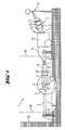
Direkt an der zu trennenden Wand befestigte Wandsägen mit einem scheibenförmigen Sägeblatt zur Abarbeitung von Stein werden im Baugewerbe beispielsweise zum Auftrennen von Wänden eingesetzt, um mittels mehrerer versetzter Schnitte eine Öffnung in der Wand zu erzeugen. Dabei ist üblicherweise die Wand selbst durch Nebenwände begrenzt, wobei unter Wand auch Boden und Decke zu verstehen ist. Der im verschiebbaren Sägekopf angeordnete Drehantrieb des Sägeblattes erfolgt dabei über hochleistungsfähige Hydraulikmotoren oder Elektromotoren, welche jeweils über flexible Leitungen mit entsprechenden separaten Versorgungsaggregaten verbunden sind.Wall saws fixed to the wall to be separated with a disc-shaped saw blade for processing stone are used in construction, for example for the separation of walls, to create an opening in the wall by means of several staggered cuts. In this case, usually the wall itself is limited by side walls, under wall and floor and ceiling is to be understood. The arranged in the sliding saw head rotary drive of the saw blade is done via high-performance hydraulic motors or electric motors, which are each connected via flexible lines with corresponding separate supply units.
Nach dem nächstliegenden Stand der Technik
Nach der
Zudem sind stationäre programmgesteuerte Steinbearbeitungsmaschinen zum vollautomatischen Trennen kompakter Felssteine bekannt, bspw. nach der
Die Aufgabe der Erfindung besteht in der Realisierung eines Steuerverfahrens für einen zumindest stückweise automatisierten Sägeprozess einer Wandsäge.The object of the invention is to realize a control method for an at least piecewise automated sawing process of a wall saw.
Die Aufgabe wird durch die Merkmale der unabhängigen Ansprüche gelöst. Vorteilhafte Weiterbildungen ergeben sich aus den Unteransprüchen.The object is solved by the features of the independent claims. Advantageous developments emerge from the subclaims.
Eine weist steuerbare Wandsäge einen längs einer Führungsschiene verschiebbaren Sägekopf mit einem Drehantrieb und einem schwenkbar verstellbaren Sägearm auf, an dessen radialem Ende ein drehend angetriebenes scheibenförmiges Sägeblatt lösbar montiert ist, wobei die Führungsschiene selbst an der zu trennenden Wand befestigbar ist und wobei ein zumindest den Sägekopf und den Sägearm steuerndes Programmsteuermittel mit Eingabe- und Ausgabemitteln vorhanden ist, welches mit einem Verschiebungssensor zur Bestimmung der Position des Sägekopfes längs der Führungsschiene und mit einem Schwenkwinkelsensor zur Bestimmung des Schwenkwinkels des Sägearms zur Längsrichtung der Führungsschiene verbunden ist.One has controllable wall saw a displaceable along a guide rail saw head with a rotary drive and a pivotally adjustable saw arm, at the radial end of a rotationally driven disc-shaped saw blade is detachably mounted, wherein the guide rail itself can be fastened to the wall to be separated and at least one saw head and the saw arm controlling program control means is provided with input and output means which is connected to a displacement sensor for determining the position of the saw head along the guide rail and with a swivel angle sensor for determining the pivot angle of the saw arm to the longitudinal direction of the guide rail.
Durch das Programmsteuermittel, den Verschiebungssensor und den Schwenkwinkelsensor ist die steuerbare Wandsäge im Sägeprozess neben einer manuellen Steuerung auch zumindest stückweise automatisiert über ein Programm steuerbar. Der Nutzer wird dadurch von seiner direkten Steueraufgabe entbunden und kann sich vermehrt der Kontrolle des zumindest stückweise automatisierten Sägeprozesses widmen.By the program control means, the displacement sensor and the swivel angle sensor, the controllable wall saw in the sawing process in addition to a manual control and at least piecewise automated controlled by a program. The user is thereby released from his direct tax task and can increasingly devote himself to the control of the at least piecewise automated sawing process.
Vorteilhaft ist das Ausgabemittel ein grafisches Display, wodurch der Sägeprozess vor Ort grafisch simuliert sowie schematisch verfolgt werden kann.Advantageously, the output means is a graphical display, whereby the sawing process can be graphically simulated and tracked on site.
Durch die periodisch abfolgende Schrittfolge des vollständig vom Programmsteuermittel programmgesteuerten Sägeprozesses einer steuerbaren Wandsäge wird der Nutzer von Routinetätigkeiten entlastet und kann sich somit voll auf die Überwachung des zumindest stückweise automatisierten Sägeprozesses konzentrieren.The periodically following step sequence of the sawing process of a controllable wall saw, which is completely program-controlled by the program control means, relieves the user of routine activities and can thus concentrate fully on the monitoring of the at least piece-by-piece automated sawing process.
Sowohl die Hinrichtung als die Rückrichtung ist eine Zugrichtung, welche mit dem Sägearm einen stumpfen Winkel ausbildet, wodurch in der stabileren Zugrichtung gesägt wird.Both the execution and the return direction is a pulling direction which forms an obtuse angle with the saw arm, thereby sawing in the more stable pulling direction.
Vorteilhaft wird zumindest im ersten Schritt vom Programmsteuermittel die Drehrichtung des Sägeblattes derart orientiert, dass in der Wand die tangentiale Schneidrichtung zur Zugrichtung orientiert ist, wodurch sich längs des Sägearms eine Zugverspannung einstellt, was zu einer stabilen Führung des Sägeblattes beiträgt und somit zu einem sauberen, engen Schnitt führt.Advantageously, at least in the first step by the program control means, the direction of rotation of the saw blade is oriented such that in the wall, the tangential cutting direction is oriented to the pulling direction, whereby along the saw arm adjusts a tensile stress, which contributes to a stable guidance of the saw blade and thus to a clean, narrow section leads.
Vorteilhaft ist zwischen dem zweiten und dem dritten Schritt ein weiterer erster Schritt eingefügt, wodurch auch die Rückwärtsrichtung zum Sägefortschritt beiträgt, wodurch die Sägegeschwindigkeit erhöht wird. Erfindungsgemäß wird der Sägearm zuvor umgeschwenkt, wodurch sowohl die Hinrichtung als auch die Rückrichtung in Zugrichtung erfolgt. Dabei wird nach dem Umschwenken das Sägeblatt bis zum nächstliegenden Wendepunkt in Druckrichtung vorgeschoben, wodurch ein exakter Schnittbeginn erreicht wird.Advantageously, a further first step is inserted between the second and the third step, whereby the reverse direction also contributes to the saw progress, whereby the sawing speed is increased. According to the saw arm is pivoted beforehand, whereby both the execution and the return direction in the pulling direction. After swiveling, the saw blade will be up to the nearest one Advancing point advanced in the pressure direction, whereby an exact cut start is achieved.
Vorteilhaft ist im manuellen Vorbereitungsprozess über das Eingabemittel eine Endtiefe eingebbar, nach dessen Abarbeitung vom vollständig vom Programmsteuermittel programmgesteuerten Sägeprozess in den Initialzustand zurückgekehrt wird, wodurch der automatisierte Sägeprozess beendet wird.Advantageously, in the manual preparation process, an end depth can be entered via the input means, after which processing is returned to the initial state by the sawing process which is completely program-controlled by the program control means, whereby the automated sawing process is ended.
Vorteilhaft ist im manuellen Vorbereitungsprozess über das Eingabemittel zumindest ein Wendepunkt als ein einseitiges Hindernis definierbar, dessen Überschreitung im vollständig vom Programmsteuermittel programmgesteuerten Sägeprozess als unzulässiger Bereich interpretiert wird, wodurch programmgesteuert sichergestellt ist, dass bei keiner Bewegung das Sägeblatt und/oder der Sägekopf das Hindernis berührt wird.In the manual preparation process, it is advantageously possible to define at least one inflection point as a one-sided obstacle, the exceeding of which is interpreted as an impermissible area in the sawing process that is completely program-controlled by the program control means, which ensures programmatically that the saw blade and / or the saw head does not touch the obstacle during any movement becomes.
Vorteilhaft wird beim Eintreten einer vom Programmsteuermittel unlösbaren topologischen/praktischen Beschränkung im Sägeprozess der Nutzer über das Ausgabemittel zum Wechsel des Sägeblattes hin zu einem anderen Sägeblattdurchmesser aufgefordert, wobei weiter vorteilhaft dessen optimaler Wert berechnet und ausgegeben wird, wodurch insbesondere zwischen zwei Seitenwänden tiefe Einschnitte ermöglicht werden.Advantageously, upon the occurrence of a topological / practical limitation in the sawing process which is unsolvable by the program control means, the user is asked to change the saw blade to another saw blade diameter, while advantageously calculating and outputting its optimum value, thereby enabling deep cuts between two side walls ,
Vorteilhaft ist im manuellen Vorbereitungsprozess über das Eingabemittel ein nicht als ein Hindernis definierter Wendepunkt als vom Programmsteuermittel veränderbarer Überschnittwendepunkt definierbar, der an der maschinenseitigen Wandseite einen Überschnitt zulässt, welcher über eine Funktion der aktuellen Schnitttiefe und des Sägeblattdurchmessers vom Programmsteuermittel berechenbar ist, bspw. über eine einfache Kreisfunktion. Am Ende des Sägeprozesses endet der Schnitt mit der Endschnitttiefe dann exakt beim gewünschten Ende, d.h. an diesem Überschnittwendepunkt, insbesondere an der, der maschinenseitigen Wandseite gegenüberliegenden, verdeckten Wandseite.Advantageously, in the manual preparation process via the input means, a turning point not defined as an obstacle is changeable by the program control means Overcut turning point definable, which allows an overcut on the machine side wall side, which can be calculated by the program control means via a function of the current cutting depth and the saw blade diameter, for example via a simple circular function. At the end of the sawing process, the cut ends with the final cutting depth then exactly at the desired end, ie at this overcut turning point, in particular at the, the machine side wall side opposite, hidden wall side.
Selbstverständlich ist die Definition eines Wendepunktes als ein Hindernis auch möglich, wenn physisch gar kein Hindernis vorhanden ist, wodurch vom Nutzer erzielt werden kann, dass nach jedem Umschwenken des Sägearms der Schnitt im Druckmodus beendet wird, wodurch ein saubereres Schnittende entsteht.Of course, the definition of an inflection point as an obstacle is also possible if there is no physical obstacle at all, whereby the user can achieve that after each swiveling of the saw arm, the cut is terminated in the print mode, resulting in a cleaner cut end.
Die Erfindung wird bezüglich eines vorteilhaften Ausführungsbeispiels näher erläutert mit:
-
Fig. 1 als Wandsäge -
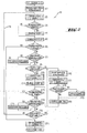
Fig. 2 als Algorithmus des Steuerverfahrens des Sägeprozesses mit einzelnen Moduln (#) -
Fig. 3a bis 3k als Ablaufschema eines Sägeprozesses zwischen zwei Seitenwänden
-
Fig. 1 as a wall saw -
Fig. 2 as algorithm of the control process of the sawing process with individual modules (#) -
Fig. 3a to 3k as a flowchart of a sawing process between two side walls
Nach
- Modul (1): gehe zum Startpunkt oder zum Hindernis
- Modul (2), Modul (10), Modul (17): schwenke zur neuen Tiefe
- Modul (3), Modul (18): Druckmodus notwendig?
- Modul (4): Druckmode
- Modul (5), Modul (20): Sägen im Zugmode
- Modul (6), Modul (12): Sägeprozess beendet?
- Modul (7), Modul (13): neuer Sägeblattdurchmesser erforderlich?
- Modul (8), Modul (14): setze neuen Sägeblattdurchmesser
- Modul (9), Modul (15): Hindernis beidseitig?
- Modul (11), Modul (19): Sägen im Druckmodus
- Modul (16): gehe zurück (falls notwendig)
- Modul (21): gehe zurück zur Ausgangsposition
- Module (1): go to the starting point or obstacle
- Module (2), module (10), module (17): swing to the new depth
- Module (3), module (18): print mode necessary?
- Module (4): Pressure mode
- Module (5), module (20): sawing in tension mode
- Module (6), Module (12): Sawing process finished?
- Module (7), module (13): new saw blade diameter required?
- Module (8), module (14): set new saw blade diameter
- Module (9), Module (15): obstacle on both sides?
- Module (11), Module (19): sawing in print mode
- Module (16): go back (if necessary)
- Module (21): go back to the starting position
Dabei erfolgt vorbereitend im nicht dargestellten manuellen Vorbereitungsprozess die Fixierung der Führungsschiene direkt an der zu sägenden Wand und die Positionierung des Sägeblattes an einer Initialposition. Zudem erfolgt über das Eingabemittel die Eingabe des Sägeblattdurchmessers, zweier Wendepunkte sowie deren wahlfreier Definition als Hindernis bzw. Überschnittwendepunkt, der Endtiefe, des Sägemodus (Sägen nur in Zugrichtung oder in Zugrichtung/Druckrichtung) und weiterer Parameter wie Wandmaterial und Armierungsstärke. Daraus wird vom Programmsteuermittel die Bestimmung der Drehzahl, der Vorschubgeschwindigkeit und der inkrementellen Schnitttiefe geeignet vorgenommen. Im aus einzelnen Moduln (#) bestehenden Algorithmus 19 des Sägeprozesses, wird nach dem Anfahren eines geeigneten Initialzustands (
Nach
Claims (8)
- Control method for a controllable wall saw (1) comprising a saw head (3) displaceable along a guide rail (2) and provided with a rotary drive (8), and a pivotably adjustable saw arm (4), wherein a rotatably driven disc-shaped saw blade (5) can be releasably mounted at the radial end of the saw arm (4),
characterised in that,
after a manual set-up process for fixing the guide rail (2) to a wall (7) to be cut, positioning the saw blade (5) in an initial position, inputting at least the saw blade diameter (d) and two reversal points (W) via the input means (14) and determining the rotational speed, the feed rate and the incremental cutting depth (S),
in a subsequent sawing process completely program-controlled by the program control means (13),
in a first step, the saw arm (4) is swivelled in the direction of the wall (7) by the incremental cutting depth (S),
in a second step, the saw head (3) is pulled along the guide rail (2) in a forward direction at the feed rate towards a first reversal point (W) in such a manner that the radial end of the saw arm (4) is directed away from the first reversal point (W) and, when the saw head (3) approaches the first reversal point (W), the saw head is reversed sufficiently far and pivoted around over the wall-free space in the direction of this obstacle and the saw head (3) is pushed towards the first reversal point (W),
and,
in a third step, the saw head (3) is pulled along the guide rail (2) in the reverse direction opposite to the forward direction towards the second reversal point (W) in such a manner that the radial end of the saw arm (4) is directed away from the second reversal point (W) and, when the saw head (3) approaches the second reversal point (W), the saw head is reversed sufficiently far and pivoted around over the wall-free space in the direction of this obstacle and the saw head (3) is pushed towards the second reversal point (W),
wherein a defined sequence of steps including at least the first step, the second step and the third step is then performed at least one further time. - Control method according to claim 1, characterised in that, at least in the first step, the direction of rotation of the saw blade (5) is oriented in such a manner by the program control means that, in the wall (7), the tangential cutting direction is oriented towards the pulling direction (Z).
- Control method according to claim 1 or claim 2, characterised in that a further first step is inserted between the second step and the third step.
- Control method according to one of the preceding claims, characterised in that, in the sawing process completely program-controlled by the program control means (13), after machining an end depth (T) that can be input via the input means (14) in the manual set-up process, the saw head (3) is returned to the initial position.
- Control method according to one of the preceding claims, characterised in that, in the sawing process completely program-controlled by the program control means (13), crossing over at least one reversal point (W) defined as an obstacle via the input means (14) in the manual set-up process is interpreted as inadmissible.
- Control method according to one of the preceding claims, characterised in that, in the sawing process completely program-controlled by the program control means (13), when a topological/practical limitation that cannot be resolved by the program control means (13) occurs in the sawing process, the user (12) is advised via the output means (15) to exchange the saw blade (5) for a saw blade with a different diameter (d), wherein its optimal value may be calculated and output.
- Control method according to one of the preceding claims, characterised in that a reversal point (W) not defined as an obstacle can be defined via the input means (14) in the manual set-up process as a cross-over reversal point that can be changed by the program control means (13) and that allows for cross-over at the wall side on the machine side, wherein the cross-over can be calculated by the program control means (13) as a function of the current cutting depth and the saw blade diameter (d).
- Computer program product that repeats a control method according to one of claims 1 to 7, executed by a microprocessor.
Applications Claiming Priority (1)
| Application Number | Priority Date | Filing Date | Title |
|---|---|---|---|
| DE200510000013 DE102005000013A1 (en) | 2005-02-22 | 2005-02-22 | Controllable wall saw and control method |
Publications (2)
| Publication Number | Publication Date |
|---|---|
| EP1693173A1 EP1693173A1 (en) | 2006-08-23 |
| EP1693173B1 true EP1693173B1 (en) | 2013-11-27 |
Family
ID=36295435
Family Applications (1)
| Application Number | Title | Priority Date | Filing Date |
|---|---|---|---|
| EP20060101001 Active EP1693173B1 (en) | 2005-02-22 | 2006-01-30 | Control method for controllable wall sawing machine |
Country Status (5)
| Country | Link |
|---|---|
| US (1) | US7337037B2 (en) |
| EP (1) | EP1693173B1 (en) |
| JP (1) | JP5201796B2 (en) |
| DE (1) | DE102005000013A1 (en) |
| ES (1) | ES2440781T3 (en) |
Cited By (7)
| Publication number | Priority date | Publication date | Assignee | Title |
|---|---|---|---|---|
| EP2993012A1 (en) | 2014-09-08 | 2016-03-09 | HILTI Aktiengesellschaft | Method for controlling a wall saw system when creating a separating cut |
| EP2993014A1 (en) | 2014-09-08 | 2016-03-09 | HILTI Aktiengesellschaft | Method for controlling a wall saw system when creating a separating cut |
| EP2993011A1 (en) | 2014-09-08 | 2016-03-09 | HILTI Aktiengesellschaft | Method for controlling a wall saw system when creating a separating cut |
| EP2993013A1 (en) | 2014-09-08 | 2016-03-09 | Hilti Aktiengesellschaft | Method for controlling a wall saw system when creating a separating cut |
| EP2993010A1 (en) | 2014-09-08 | 2016-03-09 | HILTI Aktiengesellschaft | Method for controlling a wall saw system when creating a separating cut |
| EP2993015A1 (en) | 2014-09-08 | 2016-03-09 | HILTI Aktiengesellschaft | Method for controlling a wall saw system when creating a separating cut |
| EP2993009A1 (en) | 2014-09-08 | 2016-03-09 | HILTI Aktiengesellschaft | Method for controlling a wall saw system when creating a separating cut |
Families Citing this family (17)
| Publication number | Priority date | Publication date | Assignee | Title |
|---|---|---|---|---|
| US9327424B2 (en) * | 2008-02-29 | 2016-05-03 | Husqvarna Ab | Electric saw communication |
| WO2010128903A1 (en) | 2009-05-04 | 2010-11-11 | Husqvarna Ab | A wire saw and a method of rebuilding a wall saw to a wire saw |
| US8733845B2 (en) * | 2009-08-12 | 2014-05-27 | Kevin Bollinger | Systems, machines, devices and methods for efficiently removing sidewalk trip hazards |
| EP2473305B1 (en) | 2009-09-02 | 2018-12-26 | Husqvarna AB | A saw for construction cutting work |
| US20110100183A1 (en) * | 2009-11-03 | 2011-05-05 | John Tomaino | Table saw blade height and angle adjustment mechanism |
| CN102003179B (en) * | 2010-11-05 | 2012-07-11 | 郑家富 | Saw blade type cave development machine |
| DE102011089878A1 (en) | 2011-12-23 | 2013-06-27 | Hilti Aktiengesellschaft | Device for separating a substrate and method for controlling such a separator |
| DE102013202444A1 (en) * | 2013-02-14 | 2014-08-14 | Hilti Aktiengesellschaft | Device for remote control of a tool device |
| DE102013202442B4 (en) * | 2013-02-14 | 2014-09-25 | Hilti Aktiengesellschaft | Method for controlling a device system with a tool device and a motor feed device |
| DE102013202445A1 (en) * | 2013-02-14 | 2014-08-14 | Hilti Aktiengesellschaft | Method for controlling a device system when separating a workpiece along a parting line |
| DE102013202754A1 (en) | 2013-02-20 | 2014-08-21 | Hilti Aktiengesellschaft | Device for separating a workpiece along a parting line |
| US9315955B2 (en) * | 2013-03-13 | 2016-04-19 | Ronald A. Knapp | Saw and drill machine for paved slabs |
| EP2993008A1 (en) | 2014-09-08 | 2016-03-09 | HILTI Aktiengesellschaft | Device system with a radio connection |
| GB2531523B (en) * | 2014-10-20 | 2017-11-29 | Fitzmaurice Andrew | A guide for cutting walls |
| US10105859B2 (en) | 2016-10-27 | 2018-10-23 | Andrew Fitzmaurice | Guide for cutting walls |
| EP3925749A1 (en) * | 2020-06-18 | 2021-12-22 | Hilti Aktiengesellschaft | Cutting system with saw and method of making a cut |
| EP4282608A1 (en) * | 2022-05-25 | 2023-11-29 | Hilti Aktiengesellschaft | Ground saw and method for optimized operation of a ground saw |
Family Cites Families (19)
| Publication number | Priority date | Publication date | Assignee | Title |
|---|---|---|---|---|
| US3148001A (en) * | 1962-03-26 | 1964-09-08 | Bert E Johnson | Mobile power-actuated concrete saw with reaction supporting means therefor |
| US3158001A (en) * | 1963-05-13 | 1964-11-24 | Honeywell Inc | Meter |
| JPS49106678A (en) * | 1973-02-07 | 1974-10-09 | ||
| SE451874B (en) * | 1986-04-08 | 1987-11-02 | Gearmec Ab | DEVICE FOR INSTALLING A RAIL, INTENDED FOR AN EXCELLENT WAGON OR SLIDE, ON A PARTICULARLY NON-HORIZONTAL SURFACE |
| US5680854A (en) * | 1995-01-09 | 1997-10-28 | Diamant Boart, Inc. | Self propelled saw |
| DE19601522A1 (en) * | 1996-01-17 | 1997-07-24 | Hilti Ag | Wall saw and saw blade |
| US5921228A (en) * | 1997-05-29 | 1999-07-13 | Mixer Systems, Inc. | Multi-directional, self-propelled saw for cutting concrete slabs |
| DE19823756C2 (en) * | 1998-05-27 | 2000-12-07 | Fraunhofer Ges Forschung | Self-propelled robot system for milling and drilling recesses in walls, preferably unfinished walls of buildings |
| US6131557A (en) * | 1999-04-22 | 2000-10-17 | Mixer Systems, Inc. | Two stage variable speed control for concrete saw |
| WO2002068982A2 (en) * | 2001-02-22 | 2002-09-06 | Toolz, Ltd. | Tools with orientation detection |
| US6484711B2 (en) * | 2001-02-23 | 2002-11-26 | Multiquip, Inc. | Automatic depth of cut control for concrete saw |
| WO2002070219A1 (en) * | 2001-03-01 | 2002-09-12 | Tyrolit Hydrostress Ag | Chain saw for sawing masonry |
| TWI268823B (en) * | 2003-03-04 | 2006-12-21 | Amada Co Ltd | Sawing machine, cutting processing method, and method for reducing noise |
| RU2292997C2 (en) * | 2003-10-08 | 2007-02-10 | Хитачи Коки Ко. Лтд. | Machine tool for cutting by means of inclined cutting member at indicating angle of mounting cutting member (variants) |
| CN102151897B (en) * | 2004-04-15 | 2013-06-19 | 密尔沃基电动工具公司 | Power tool |
| JP4539196B2 (en) * | 2004-06-30 | 2010-09-08 | 日立工機株式会社 | Tabletop cutting machine |
| JP4984313B2 (en) * | 2004-06-30 | 2012-07-25 | 日立工機株式会社 | Tabletop cutting machine |
| JP4743472B2 (en) * | 2004-06-30 | 2011-08-10 | 日立工機株式会社 | Tabletop cutting machine |
| US20070194617A1 (en) * | 2006-02-20 | 2007-08-23 | Diamond Products, Limited | Self-propelled concrete saw with forward motion speed control system |
-
2005
- 2005-02-22 DE DE200510000013 patent/DE102005000013A1/en not_active Withdrawn
-
2006
- 2006-01-30 ES ES06101001T patent/ES2440781T3/en active Active
- 2006-01-30 EP EP20060101001 patent/EP1693173B1/en active Active
- 2006-02-21 US US11/359,797 patent/US7337037B2/en active Active
- 2006-02-21 JP JP2006044291A patent/JP5201796B2/en active Active
Cited By (18)
| Publication number | Priority date | Publication date | Assignee | Title |
|---|---|---|---|---|
| EP2993012A1 (en) | 2014-09-08 | 2016-03-09 | HILTI Aktiengesellschaft | Method for controlling a wall saw system when creating a separating cut |
| EP2993014A1 (en) | 2014-09-08 | 2016-03-09 | HILTI Aktiengesellschaft | Method for controlling a wall saw system when creating a separating cut |
| EP2993011A1 (en) | 2014-09-08 | 2016-03-09 | HILTI Aktiengesellschaft | Method for controlling a wall saw system when creating a separating cut |
| EP2993013A1 (en) | 2014-09-08 | 2016-03-09 | Hilti Aktiengesellschaft | Method for controlling a wall saw system when creating a separating cut |
| EP2993010A1 (en) | 2014-09-08 | 2016-03-09 | HILTI Aktiengesellschaft | Method for controlling a wall saw system when creating a separating cut |
| EP2993015A1 (en) | 2014-09-08 | 2016-03-09 | HILTI Aktiengesellschaft | Method for controlling a wall saw system when creating a separating cut |
| EP2993009A1 (en) | 2014-09-08 | 2016-03-09 | HILTI Aktiengesellschaft | Method for controlling a wall saw system when creating a separating cut |
| WO2016037911A1 (en) | 2014-09-08 | 2016-03-17 | Hilti Aktiengesellschaft | Method for controlling a wall saw system during the creation of a separating cut |
| WO2016037891A1 (en) | 2014-09-08 | 2016-03-17 | Hilti Aktiengesellschaft | Method for controlling a wall saw system when creating a separating cut |
| WO2016037902A1 (en) | 2014-09-08 | 2016-03-17 | Hilti Aktiengesellschaft | Method for controlling a wall saw system during the creation of a separating cut |
| WO2016037915A1 (en) * | 2014-09-08 | 2016-03-17 | Hilti Aktiengesellschaft | Method for controlling a wall saw system during the creation of a separation cut |
| WO2016037906A1 (en) * | 2014-09-08 | 2016-03-17 | Hilti Aktiengesellschaft | Method for controlling a wall saw system during the creation of a separating cut |
| WO2016037896A1 (en) | 2014-09-08 | 2016-03-17 | Hilti Aktiengesellschaft | Method for controlling a wall saw system during the creation of a separating cut |
| WO2016037920A1 (en) | 2014-09-08 | 2016-03-17 | Hilti Aktiengesellschaft | Method for controlling a wall saw system during the creation of a separation cut |
| EP3191275A1 (en) * | 2014-09-08 | 2017-07-19 | Hilti Aktiengesellschaft | Method for controlling a wall saw system when creating a separating cut |
| US10513050B2 (en) | 2014-09-08 | 2019-12-24 | Hilti Aktiengesellschaft | Method for controlling a wall saw system during the creation of a separation cut |
| US10569446B2 (en) | 2014-09-08 | 2020-02-25 | Hilti Aktiengesellschaft | Method for controlling a wall saw system when making a separating cut |
| US10821630B2 (en) | 2014-09-08 | 2020-11-03 | Hilti Aktiengesellschaft | Method for controlling a wall saw system during the creation of a separation cut |
Also Published As
| Publication number | Publication date |
|---|---|
| US20060189258A1 (en) | 2006-08-24 |
| EP1693173A1 (en) | 2006-08-23 |
| ES2440781T3 (en) | 2014-01-30 |
| JP2006231920A (en) | 2006-09-07 |
| US7337037B2 (en) | 2008-02-26 |
| DE102005000013A1 (en) | 2006-08-31 |
| JP5201796B2 (en) | 2013-06-05 |
Similar Documents
| Publication | Publication Date | Title |
|---|---|---|
| EP1693173B1 (en) | Control method for controllable wall sawing machine | |
| EP2956268B1 (en) | Method of controlling a tool system with a tool and a motorised feed device | |
| CN111745095A (en) | Equipment for equally cutting and segmenting reinforcing steel bars | |
| EP1579965A1 (en) | Apparatus for machining a frontal end of a profile forming a negative form of a branch of a sewer | |
| WO2014090589A2 (en) | Machine for digging roadways, tunnels or the like and method for working head controlling | |
| DE2706187B2 (en) | Method and device for producing a groove in an existing wall surface | |
| WO2016037920A1 (en) | Method for controlling a wall saw system during the creation of a separation cut | |
| EP2993011A1 (en) | Method for controlling a wall saw system when creating a separating cut | |
| DE7729113U1 (en) | DEVICE FOR BENDING TIRE LAYERS | |
| DE102009037298B4 (en) | Arrangement and method for sharpening a saw blade and use of the arrangement | |
| EP2993009A1 (en) | Method for controlling a wall saw system when creating a separating cut | |
| EP3191276A1 (en) | Method for controlling a wall saw system during the creation of a separating cut | |
| EP2993013A1 (en) | Method for controlling a wall saw system when creating a separating cut | |
| DE202006008246U1 (en) | Machine with saw blades rotatable into two directions e.g. for cutting slots, has cutting blades with power source provided in housing and power source propels and turns shaft with blade connected to end of it | |
| EP2404691B1 (en) | Rotating ring used for machining profiles | |
| EP2993015A1 (en) | Method for controlling a wall saw system when creating a separating cut | |
| EP3191279B1 (en) | Method for controlling a wall saw system when creating a separating cut | |
| WO2015135909A1 (en) | Wire saw device and use of a wire saw device | |
| EP1136163A2 (en) | Circular saw with scoring device | |
| EP0238648A1 (en) | Process and device for making deep cuts in concrete or similar material. | |
| EP2786823B1 (en) | Device for optional sharpening of ribbon and gang saw blades | |
| DE735214C (en) | Machine for mining coal | |
| CH703967A1 (en) | Control device for a machine tool. | |
| DE596921C (en) | ||
| DE202005002873U1 (en) | Stone block cutting system for use in quarry has very high pressure water jet acting as cutter, and mounted on carriage on rail track laid on floor of quarry |
Legal Events
| Date | Code | Title | Description |
|---|---|---|---|
| PUAI | Public reference made under article 153(3) epc to a published international application that has entered the european phase |
Free format text: ORIGINAL CODE: 0009012 |
|
| AK | Designated contracting states |
Kind code of ref document: A1 Designated state(s): AT BE BG CH CY CZ DE DK EE ES FI FR GB GR HU IE IS IT LI LT LU LV MC NL PL PT RO SE SI SK TR |
|
| AX | Request for extension of the european patent |
Extension state: AL BA HR MK YU |
|
| 17P | Request for examination filed |
Effective date: 20070223 |
|
| AKX | Designation fees paid |
Designated state(s): AT BE BG CH CY CZ DE DK EE ES FI FR GB GR HU IE IS IT LI LT LU LV MC NL PL PT RO SE SI SK TR |
|
| 17Q | First examination report despatched |
Effective date: 20081202 |
|
| GRAP | Despatch of communication of intention to grant a patent |
Free format text: ORIGINAL CODE: EPIDOSNIGR1 |
|
| INTG | Intention to grant announced |
Effective date: 20130724 |
|
| GRAS | Grant fee paid |
Free format text: ORIGINAL CODE: EPIDOSNIGR3 |
|
| GRAA | (expected) grant |
Free format text: ORIGINAL CODE: 0009210 |
|
| AK | Designated contracting states |
Kind code of ref document: B1 Designated state(s): AT BE BG CH CY CZ DE DK EE ES FI FR GB GR HU IE IS IT LI LT LU LV MC NL PL PT RO SE SI SK TR |
|
| REG | Reference to a national code |
Ref country code: GB Ref legal event code: FG4D Free format text: NOT ENGLISH |
|
| REG | Reference to a national code |
Ref country code: CH Ref legal event code: EP |
|
| REG | Reference to a national code |
Ref country code: AT Ref legal event code: REF Ref document number: 642486 Country of ref document: AT Kind code of ref document: T Effective date: 20131215 |
|
| REG | Reference to a national code |
Ref country code: IE Ref legal event code: FG4D Free format text: LANGUAGE OF EP DOCUMENT: GERMAN |
|
| REG | Reference to a national code |
Ref country code: DE Ref legal event code: R096 Ref document number: 502006013380 Country of ref document: DE Effective date: 20140123 |
|
| REG | Reference to a national code |
Ref country code: ES Ref legal event code: FG2A Ref document number: 2440781 Country of ref document: ES Kind code of ref document: T3 Effective date: 20140130 |
|
| REG | Reference to a national code |
Ref country code: SE Ref legal event code: TRGR |
|
| REG | Reference to a national code |
Ref country code: NL Ref legal event code: VDEP Effective date: 20131127 |
|
| REG | Reference to a national code |
Ref country code: LT Ref legal event code: MG4D |
|
| PG25 | Lapsed in a contracting state [announced via postgrant information from national office to epo] |
Ref country code: IS Free format text: LAPSE BECAUSE OF FAILURE TO SUBMIT A TRANSLATION OF THE DESCRIPTION OR TO PAY THE FEE WITHIN THE PRESCRIBED TIME-LIMIT Effective date: 20140327 Ref country code: FI Free format text: LAPSE BECAUSE OF FAILURE TO SUBMIT A TRANSLATION OF THE DESCRIPTION OR TO PAY THE FEE WITHIN THE PRESCRIBED TIME-LIMIT Effective date: 20131127 Ref country code: NL Free format text: LAPSE BECAUSE OF FAILURE TO SUBMIT A TRANSLATION OF THE DESCRIPTION OR TO PAY THE FEE WITHIN THE PRESCRIBED TIME-LIMIT Effective date: 20131127 Ref country code: LT Free format text: LAPSE BECAUSE OF FAILURE TO SUBMIT A TRANSLATION OF THE DESCRIPTION OR TO PAY THE FEE WITHIN THE PRESCRIBED TIME-LIMIT Effective date: 20131127 |
|
| PG25 | Lapsed in a contracting state [announced via postgrant information from national office to epo] |
Ref country code: LV Free format text: LAPSE BECAUSE OF FAILURE TO SUBMIT A TRANSLATION OF THE DESCRIPTION OR TO PAY THE FEE WITHIN THE PRESCRIBED TIME-LIMIT Effective date: 20131127 Ref country code: CY Free format text: LAPSE BECAUSE OF FAILURE TO SUBMIT A TRANSLATION OF THE DESCRIPTION OR TO PAY THE FEE WITHIN THE PRESCRIBED TIME-LIMIT Effective date: 20131127 |
|
| PG25 | Lapsed in a contracting state [announced via postgrant information from national office to epo] |
Ref country code: PT Free format text: LAPSE BECAUSE OF FAILURE TO SUBMIT A TRANSLATION OF THE DESCRIPTION OR TO PAY THE FEE WITHIN THE PRESCRIBED TIME-LIMIT Effective date: 20140327 |
|
| BERE | Be: lapsed |
Owner name: HILTI AKTIENGESELLSCHAFT Effective date: 20140131 |
|
| PG25 | Lapsed in a contracting state [announced via postgrant information from national office to epo] |
Ref country code: EE Free format text: LAPSE BECAUSE OF FAILURE TO SUBMIT A TRANSLATION OF THE DESCRIPTION OR TO PAY THE FEE WITHIN THE PRESCRIBED TIME-LIMIT Effective date: 20131127 |
|
| REG | Reference to a national code |
Ref country code: DE Ref legal event code: R097 Ref document number: 502006013380 Country of ref document: DE |
|
| PG25 | Lapsed in a contracting state [announced via postgrant information from national office to epo] |
Ref country code: RO Free format text: LAPSE BECAUSE OF FAILURE TO SUBMIT A TRANSLATION OF THE DESCRIPTION OR TO PAY THE FEE WITHIN THE PRESCRIBED TIME-LIMIT Effective date: 20131127 Ref country code: PL Free format text: LAPSE BECAUSE OF FAILURE TO SUBMIT A TRANSLATION OF THE DESCRIPTION OR TO PAY THE FEE WITHIN THE PRESCRIBED TIME-LIMIT Effective date: 20131127 Ref country code: MC Free format text: LAPSE BECAUSE OF FAILURE TO SUBMIT A TRANSLATION OF THE DESCRIPTION OR TO PAY THE FEE WITHIN THE PRESCRIBED TIME-LIMIT Effective date: 20131127 Ref country code: LU Free format text: LAPSE BECAUSE OF FAILURE TO SUBMIT A TRANSLATION OF THE DESCRIPTION OR TO PAY THE FEE WITHIN THE PRESCRIBED TIME-LIMIT Effective date: 20140130 Ref country code: SK Free format text: LAPSE BECAUSE OF FAILURE TO SUBMIT A TRANSLATION OF THE DESCRIPTION OR TO PAY THE FEE WITHIN THE PRESCRIBED TIME-LIMIT Effective date: 20131127 Ref country code: CZ Free format text: LAPSE BECAUSE OF FAILURE TO SUBMIT A TRANSLATION OF THE DESCRIPTION OR TO PAY THE FEE WITHIN THE PRESCRIBED TIME-LIMIT Effective date: 20131127 |
|
| PG25 | Lapsed in a contracting state [announced via postgrant information from national office to epo] |
Ref country code: DK Free format text: LAPSE BECAUSE OF FAILURE TO SUBMIT A TRANSLATION OF THE DESCRIPTION OR TO PAY THE FEE WITHIN THE PRESCRIBED TIME-LIMIT Effective date: 20131127 |
|
| PLBE | No opposition filed within time limit |
Free format text: ORIGINAL CODE: 0009261 |
|
| STAA | Information on the status of an ep patent application or granted ep patent |
Free format text: STATUS: NO OPPOSITION FILED WITHIN TIME LIMIT |
|
| 26N | No opposition filed |
Effective date: 20140828 |
|
| REG | Reference to a national code |
Ref country code: IE Ref legal event code: MM4A |
|
| REG | Reference to a national code |
Ref country code: DE Ref legal event code: R097 Ref document number: 502006013380 Country of ref document: DE Effective date: 20140828 |
|
| PG25 | Lapsed in a contracting state [announced via postgrant information from national office to epo] |
Ref country code: BE Free format text: LAPSE BECAUSE OF NON-PAYMENT OF DUE FEES Effective date: 20140131 Ref country code: IE Free format text: LAPSE BECAUSE OF NON-PAYMENT OF DUE FEES Effective date: 20140130 |
|
| PG25 | Lapsed in a contracting state [announced via postgrant information from national office to epo] |
Ref country code: SI Free format text: LAPSE BECAUSE OF FAILURE TO SUBMIT A TRANSLATION OF THE DESCRIPTION OR TO PAY THE FEE WITHIN THE PRESCRIBED TIME-LIMIT Effective date: 20131127 |
|
| REG | Reference to a national code |
Ref country code: FR Ref legal event code: PLFP Year of fee payment: 11 |
|
| PG25 | Lapsed in a contracting state [announced via postgrant information from national office to epo] |
Ref country code: BG Free format text: LAPSE BECAUSE OF FAILURE TO SUBMIT A TRANSLATION OF THE DESCRIPTION OR TO PAY THE FEE WITHIN THE PRESCRIBED TIME-LIMIT Effective date: 20131127 |
|
| PG25 | Lapsed in a contracting state [announced via postgrant information from national office to epo] |
Ref country code: GR Free format text: LAPSE BECAUSE OF FAILURE TO SUBMIT A TRANSLATION OF THE DESCRIPTION OR TO PAY THE FEE WITHIN THE PRESCRIBED TIME-LIMIT Effective date: 20140228 |
|
| PG25 | Lapsed in a contracting state [announced via postgrant information from national office to epo] |
Ref country code: TR Free format text: LAPSE BECAUSE OF FAILURE TO SUBMIT A TRANSLATION OF THE DESCRIPTION OR TO PAY THE FEE WITHIN THE PRESCRIBED TIME-LIMIT Effective date: 20131127 Ref country code: HU Free format text: LAPSE BECAUSE OF FAILURE TO SUBMIT A TRANSLATION OF THE DESCRIPTION OR TO PAY THE FEE WITHIN THE PRESCRIBED TIME-LIMIT; INVALID AB INITIO Effective date: 20060130 |
|
| REG | Reference to a national code |
Ref country code: FR Ref legal event code: PLFP Year of fee payment: 12 |
|
| REG | Reference to a national code |
Ref country code: FR Ref legal event code: PLFP Year of fee payment: 13 |
|
| PGFP | Annual fee paid to national office [announced via postgrant information from national office to epo] |
Ref country code: FR Payment date: 20230124 Year of fee payment: 18 Ref country code: ES Payment date: 20230330 Year of fee payment: 18 Ref country code: CH Payment date: 20230124 Year of fee payment: 18 Ref country code: AT Payment date: 20230120 Year of fee payment: 18 |
|
| PGFP | Annual fee paid to national office [announced via postgrant information from national office to epo] |
Ref country code: SE Payment date: 20230119 Year of fee payment: 18 Ref country code: IT Payment date: 20230120 Year of fee payment: 18 Ref country code: GB Payment date: 20230119 Year of fee payment: 18 Ref country code: DE Payment date: 20230123 Year of fee payment: 18 |
|
| PGFP | Annual fee paid to national office [announced via postgrant information from national office to epo] |
Ref country code: ES Payment date: 20240223 Year of fee payment: 19 |
|
| PGFP | Annual fee paid to national office [announced via postgrant information from national office to epo] |
Ref country code: AT Payment date: 20240122 Year of fee payment: 19 |