EP2786823B1 - Device for optional sharpening of ribbon and gang saw blades - Google Patents
Device for optional sharpening of ribbon and gang saw blades Download PDFInfo
- Publication number
- EP2786823B1 EP2786823B1 EP14001244.4A EP14001244A EP2786823B1 EP 2786823 B1 EP2786823 B1 EP 2786823B1 EP 14001244 A EP14001244 A EP 14001244A EP 2786823 B1 EP2786823 B1 EP 2786823B1
- Authority
- EP
- European Patent Office
- Prior art keywords
- tool
- machine bed
- machining
- feed device
- axis
- Prior art date
- Legal status (The legal status is an assumption and is not a legal conclusion. Google has not performed a legal analysis and makes no representation as to the accuracy of the status listed.)
- Not-in-force
Links
Images

Classifications
-
- B—PERFORMING OPERATIONS; TRANSPORTING
- B23—MACHINE TOOLS; METAL-WORKING NOT OTHERWISE PROVIDED FOR
- B23D—PLANING; SLOTTING; SHEARING; BROACHING; SAWING; FILING; SCRAPING; LIKE OPERATIONS FOR WORKING METAL BY REMOVING MATERIAL, NOT OTHERWISE PROVIDED FOR
- B23D63/00—Dressing the tools of sawing machines or sawing devices for use in cutting any kind of material, e.g. in the manufacture of sawing tools
- B23D63/001—Devices for positioning the dressing tool with respect to the saw blade
-
- B—PERFORMING OPERATIONS; TRANSPORTING
- B23—MACHINE TOOLS; METAL-WORKING NOT OTHERWISE PROVIDED FOR
- B23D—PLANING; SLOTTING; SHEARING; BROACHING; SAWING; FILING; SCRAPING; LIKE OPERATIONS FOR WORKING METAL BY REMOVING MATERIAL, NOT OTHERWISE PROVIDED FOR
- B23D63/00—Dressing the tools of sawing machines or sawing devices for use in cutting any kind of material, e.g. in the manufacture of sawing tools
- B23D63/005—Workpiece indexing equipment specially adapted to form part of sawing tool dressing machines
-
- B—PERFORMING OPERATIONS; TRANSPORTING
- B23—MACHINE TOOLS; METAL-WORKING NOT OTHERWISE PROVIDED FOR
- B23D—PLANING; SLOTTING; SHEARING; BROACHING; SAWING; FILING; SCRAPING; LIKE OPERATIONS FOR WORKING METAL BY REMOVING MATERIAL, NOT OTHERWISE PROVIDED FOR
- B23D63/00—Dressing the tools of sawing machines or sawing devices for use in cutting any kind of material, e.g. in the manufacture of sawing tools
- B23D63/008—Dressing the tools of sawing machines or sawing devices for use in cutting any kind of material, e.g. in the manufacture of sawing tools using computer control means
-
- B—PERFORMING OPERATIONS; TRANSPORTING
- B23—MACHINE TOOLS; METAL-WORKING NOT OTHERWISE PROVIDED FOR
- B23D—PLANING; SLOTTING; SHEARING; BROACHING; SAWING; FILING; SCRAPING; LIKE OPERATIONS FOR WORKING METAL BY REMOVING MATERIAL, NOT OTHERWISE PROVIDED FOR
- B23D63/00—Dressing the tools of sawing machines or sawing devices for use in cutting any kind of material, e.g. in the manufacture of sawing tools
- B23D63/08—Sharpening the cutting edges of saw teeth
Definitions
- the present invention relates to a device according to the preamble of claim 1 for sharpening elongated sawing tools
- a device for sharpening elongated sawing tools
- a base having an elongate machine bed
- a fixing device adapted to fix the saw tool to be processed relative to the machine bed
- a machining head having an axis of rotation for driving a rotary tool and a lifting axis for height-adjusting the rotary tool relative to the machine bed, and a method according to the preamble of claim 15.
- the machining head is arranged generally stationary relative to the machine bed.
- the rotary tool is adjusted by means of an additionally provided on the machining head pivot axis corresponding to an angle of the tooth profile of the sawing tool and introduced for machining by means of the stroke axis in the tooth profile.
- the rotary tool is guided along the contour of the sawing tool, which is also referred to as profile grinding or sharpening.
- the sawing tool is machined in the area between two adjacent tooth tips, in other words in a division or gap manner.
- the processing is carried out starting from a first tooth along the tooth face and the tooth base and then along the tooth back and the free surface of an adjacent tooth.
- the machining length machined by the rotary tool during a machining operation thus essentially corresponds to the pitch of the toothed profile.
- the sawing tool is displaced during or subsequently respectively relative to the rotary tool, so that after a completed gap-machining operation, an unprocessed portion of the sawing tool is disposed below the rotary tool. Accordingly, the processing of a multi-tooth sawing tool in the prior art is carried out as a sequence of individual gaps processing operations with a respective displacement operation of the sawing tool.
- the document DE 195 18 710 C1 discloses a device in which a rotary tool is aligned in the form of a grinding wheel by means of a pivot axis corresponding to the course of a tooth face of a sawing tool, ie according to the rake angle of the tooth profile.
- a sawing tool is so below
- the grinding wheel positions the tooth face of a saw tooth opposite the grinding wheel. Subsequently, the grinding wheel is lowered by means of a lifting axis in the tooth profile, to edit the tooth face grinding.
- the device described in this document comprises a feed device, which has a feed arm with a feed finger extending transversely to the longitudinal direction of the sawing tool.
- This feed arm is moved by means of a cross slide of the feed device transversely to the sawing tool, so that the feed finger engages in a tooth gap of the sawing tool, which is adjacent to the currently operated by the grinding wheel tooth gap.
- the cross slide is displaceable by means of a feed axis, so that the sawing tool is displaceable by the distance of a pitch after the engagement of the feed finger relative to the machine bed and rotary tool. If the grinding wheel reaches the tooth base after machining the tooth face, the transverse slide is displaced in the direction of the grinding wheel by means of the feed axis so that it moves in the opposite direction relative to the longitudinal direction of the sawing tool.
- the movement of the lifting axis and the feed axis are coordinated in such a way that the grinding wheel executes a predetermined movement, which is oriented on a nominal contour of the toothed profile.
- the grinding wheel is extended by means of the lifting axis of the tooth profile.
- the sawing tool is further displaced by means of the feed device in a starting position for the processing of the following tooth gap.
- the feed arm is set back by a coordinated movement of cross slide and feed axis by the distance of a pitch to intervene in the manner described above in an adjacent tooth gap.
- the machining of the sawing tool is performed in gaps with a respective feed of the sawing tool along the machine bed by the distance of a pitch.
- the sawing tool is actively displaced in phase from the feed device during processing.
- the sawing tool is not fixed relative to the machine bed, which is disadvantageous in terms of its rigidity against the grinding wheel.
- the engagement of the feed device on the sawing tool takes place on possibly not yet machined sections of the toothed profile. This means that the accuracy of processing a tooth gap is dependent on the state of the adjacent tooth gap, which engages the feed device.
- the feed movement of the feed axis is typically specified as a constant value, for example as the amount of tooth pitch.
- the sawing tool Softens the tooth gap and especially the tooth face the attack of the advancing device of an expected nominal contour of the tooth profile, the sawing tool is correspondingly further or less displaced than specified. Accordingly, in such a device, the pitch along the sawing tool may vary continuously after machining. Such errors occur even when wear of the feed finger and can propagate over a variety of teeth. Furthermore, after a tooth gap has been worked, a certain amount of time is always required to reposition the feed finger in an adjacent tooth space, release the saw tool, perform the feed, and fix the saw tool again. This increases the processing time of a multi-tooth sawing tool.
- the processing of the immovable sawing tool is similar to that described above by means of a grinding wheel.
- the relative movement between the grinding wheel and sawing tool is not realized during machining with the aid of a feed device.
- a translationally acting, so-called X-axis is provided at the machining head at right angles to the stroke axis.
- the movements of stroke axis and X-axis are coordinated so that the grinding wheel is guided along the tooth profile of the sawing tool.
- the processing is again in gaps, ie with a processing length corresponding to a pitch of the tooth profile.
- a feed device is provided on a separate carriage, which engages in a combined pivoting and translational movement in a tooth space adjacent to the machined tooth space to displace the saw tool relative to the grinding wheel by the distance of a pitch.
- the document DE 103 51 151 B3 also describes a device for sharpening band saw blades.
- This document also describes a conventional kinematics, in which a machining head along a lifting axis Y is movable.
- the device described therein has a feed device, which allows an oscillating displacement of a feed finger.
- the band saw blade can be displaced stepwise in the direction of its longitudinal extension along a feed axis X.
- a simultaneous movement of the lifting axis Y and the feed axis X can take place.
- machining head is displaceable by means of a linear movement axis along the machine bed such that a fixed sawing tool can be machined along a predetermined processing length comprising a plurality of teeth
- a feed device is provided adapted to displace the sawing tool either by the distance of a single tooth or by the distance of the predetermined processing length including a plurality of teeth along the machine bed.
- the feed device offers the advantage that the sawing tool is displaceable by a distance which is greater than only the distance of a division, and in particular by a distance accordingly the processing length is displaced. This makes it possible for sawing tools to be processed in a time-saving manner as a function of the machining length with the least possible number of displacement processes. This is particularly advantageous in band saw blades or tool blanks in the form of coils or bands, which are only partially processed due to their closed circular shape and their length and therefore must be relocated in each case relative to the machine bed.
- the self-adjusting pitch of the tooth profile is also constant at least in sections, wherein the sections each include a number of teeth corresponding to the predetermined processing length.
- the movements of the lifting axis and the linear movement axis can be coordinated in such a way that the rotary tool is guided in a known manner contour-exactly along the toothing profile.
- the term "linear motion axis” refers to the linear motion performed by this axis. It is understood that this movement can be achieved in various ways known per se, for example by means of toothed racks, threaded rods, linear drives or the like.
- the term "rotary tool” is to be understood as meaning all tools driven for rotation and suitable for sharpening sawing tools, but in particular grinding wheels and eroding tools. Alternatively, an EDM wire can be used.
- sawing tool in particular also refers to unsmooth or pre-toothed blanks, which are provided with a first or final toothing when being machined by the device according to the invention.
- processing of end-serrated sawing tools is provided which, for example, are to be reworked as a result of operational wear.
- the processing of a sawing tool with the device according to the invention is carried out such that the sawing tool is first fixed in a predetermined position within the device. Coordinating the movements of linear movement axis and lifting axis, the rotary tool is guided along the tooth profile of the sawing tool. After covering a given processing length is the rotary tool is extended from the tooth profile and the machining head is moved back into its starting position by means of the linear movement axis. Furthermore, the sawing tool is displaced by the amount of the predetermined machining length relative to the machine bed and thus also relative to the starting position of the machining head. These steps can be repeated until the saw tool is machined along its entire length. The greater the machining length is selected, the lower the number of necessary displacements of the sawing tool by the feed device and the lower the known from the prior art impairments of accuracy and processing time.
- linear movement axis and feed device can also be coordinated in other ways.
- a development of the invention provides that the feed device can be displaced along the machine bed either by the distance of a single tooth or by the distance of the predetermined processing length comprising a plurality of teeth.
- a displacement of the feed device per se means that the feed device can be constantly positioned relative to the sawing tool during the displacement process. This allows any feed members with which the feed device comes into contact with the sawing tool, space-saving design can be constructed.
- the feed device is displaceable by means of a separately provided movement axis along the machine bed.
- a separate movement axis makes it possible for the feed device to be specifically and independently activatable.
- such a movement axis can also be specially adapted to particular requirements of the feed device.
- a development of the invention provides that the feed device is arranged on the machining head, so that it can be displaced together with the latter by means of the linear movement axis.
- the provision of a separate movement axis for the feed device is obsolete.
- both cost and space can be saved and the introduction of Vibrations can be reduced by several independently acting axes of motion.
- the movement of the machining head can be directly coupled to its starting position after covering the predetermined processing length with the displacement of the sawing tool. This coupled execution of the movements of the machining head and feed device shortens the machining time of the sawing tool.
- a development of the invention provides that the feed device engages with frictional engagement with the sawing tool in order to displace it.
- the frictional engagement can be achieved, for example, by establishing a clamping connection between the feed device and the sawing tool or by enclosing the sawing tool between a pair of rollers.
- Such solutions make it possible for the feed device to engage the sawing tool independently of the tooth profile. It is understood that the feed motion can also be sensed to improve the accuracy of the displacement process.
- the feed device engages under positive engagement on the sawing tool in order to displace this.
- a positive connection can be achieved in particular by engagement of the feed device in the tooth profile of the sawing tool.
- the feed device can preferably engage in such areas of the tooth profile, which have low manufacturing tolerances or small tolerances due to wear after operation of the sawing tool.
- Such small tolerances of the tooth profile reduce adverse effects on the amount of displacement of the sawing tool and allow accurate positioning of the sawing tool relative to the rotary tool.
- An even higher accuracy can be achieved if the feed device builds a form fit to the sawing tool within an already machined by the device portion of the tooth profile. Such areas have particularly small deviations from the desired contour of the tooth profile.
- the feed device has a driving finger which is movable from a rest position into a driving position in which it comes into contact with the sawing tool in order to displace it.
- the rest position is selected such that the sawing tool can be moved relative to the driving finger, while in the driving position driving finger and sawing tool can only be moved together.
- the driving finger can be geometrically adapted to the area of the sawing tool, with which he comes into contact. This ensures that the feed forces applied by the feed device are converted with high accuracy into a movement of the sawing tool.
- the movement of the driving finger into the driving position takes place by means of a separate movement axis.
- This allows the movement of the driving finger can be precisely controlled with a specially suitable movement axis.
- the driving finger is designed such that it can be moved transversely to the longitudinal axis of the machine bed into its driving position.
- a corresponding movement of the driving finger is also transverse to the longitudinal axis of the sawing tool.
- the feed device acts on the sawing tool substantially in the same region as the rotary tool in order to displace it. This allows a particularly compact built unit of machining head and feed device. It can be provided in particular that the feed device engages in an immediately machined portion of the rotary tool, whereby a high accuracy with respect to the relative position of feed device and sawing tool can be achieved.
- a development of the invention provides that the machining head comprises a pivot axis for pivoting the rotary tool relative to the machine bed. This allows a variable alignment of the rotary tool in accordance with a present tooth profile of a sawing tool, optionally with the additional setting of a slope, a so-called "fall".
- the feed device is arranged on the machining head such that it can be pivoted together with the rotary tool by means of the pivot axis.
- such an attack of the feed device on the sawmill train can be achieved in a simple manner, in which the feed device and rotating tool engage substantially in the same area of the sawing tool.
- the feed device can be controlled by means of a CNC control.
- a CNC control By means of such a control, the respective axes of the device can be precisely coordinated and the movements to be executed can be programmed in a known manner or predefined on the basis of stored data records.
- the pivot axis is arranged such that it pivots the rotary tool about a horizontal spatial axis, which is arranged substantially at right angles to the longitudinal axis of the machine bed.
- Specifying the axis movements in steps a) and b) can be done in particular by depositing corresponding data sets or program commands in a CNC control of the device.
- the pivot axis can be set to a fixed value and carried the leadership of the rotary tool along the tooth profile of the sawing tool via coordinated movements of stroke axis and linear axis of movement. In this case, the pivot axis be adjusted according to the rake angle of the tooth profile of the sawing tool to be machined.
- steps d) and e) can also be performed overlapping in time or in parallel, in particular in a device in which the feed device according to the invention is arranged on the machining head.
- the rotary tool is extended for example by means of the lifting axis of the tooth profile of the sawing tool and the feed device comes into contact with the sawing tool.
- the machining head and the feed device are displaced together by the distance of the processing length to an initial position by means of the linear movement axis.
- the steps a) to e) are repeated at least until each tooth of the sawing tool has been processed once. It is advantageous according to a development of the method according to the invention, when the repetition of the method steps, the steps a) and b) are executed only again when the axis movements to be performed differ from those of the previous run.
- Such a processing method enables time-optimized machining of the sawing tool.
- the predetermined machining length can be chosen as large as possible to edit the sawing tool with as few feed operations.
- a device according to the invention is shown and generally designated 10.
- the apparatus 10 has a base with an elongate machine bed 12.
- a substantially along this machine bed extending sawing tool 14 in the form of an endless band saw blade has at its in Fig. 1 upper circumferential edge of a tooth profile 16.
- the band saw blade 14 is generally shaped as a closed body, which assumes oval shapes depending on the voltages introduced.
- the band saw blade is shaped substantially as an elongate oval and also includes opposing parallel sections.
- the band saw blade 14 has a pronounced longitudinal axis which is parallel to the longitudinal axis of the machine bed 12.
- the sawing tool 14 is further fixed by means of a fixing direction 18 relative to the machine bed 12.
- the device 10 further comprises a machining head 20.
- This comprises a rotation axis R which is provided to drive a rotary tool 22, in this case a grinding wheel.
- the rotational axis R and the rotary tool 22 are arranged on a lifting axis H such that the rotary tool 22 is height-adjustable relative to the machine bed 12.
- the lifting axis H is in turn pivotable relative to the machine bed 12 by means of a pivot axis S.
- the pivot axis S is arranged on a linear movement axis L, by means of which the machining head 20 is displaceable along the machine bed 12.
- the working space of the device 10 is surrounded by a machine housing 24, which has an openable portion 26.
- This section 26 is pivoted or hinged in a conventional manner relative to the machine housing 24, so that in particular band saw blades of in Fig. 1 can be inserted above the device 10 in the working space.
- the machine housing 24 and its openable portion 26 is shown partially broken to better recognize the other components of the device can.
- the sawing tool 14 is held and guided by support devices, not shown, known per se, in particular in the rear part of the device 10, not shown.
- Fig. 1 If the machining length specified for the present machining process is marked with a double arrow B This in Fig. 1 The left end of the arrow B represents the starting position of the machining head 20. Accordingly, the machining head 20 is located in Fig.1 in its maximum deflected position. During the machining of the tooth profile 16, the machining head 20 is displaced from its initial position by means of the linear movement axis L in the direction of the maximum deflected position. In this case, the height of the rotary tool 22 is controlled relative to the machine bed 12 by means of the lifting axis H in coordination with the movement of the linear movement axis L. The setting of the pivot axis S is set at the beginning of processing in dependence on the rake angle of the present tooth profile 16 and not varied during processing. Thus, the rotary tool 22 is guided in a conventional manner along the contour of the tooth profile 16.
- a feed device 28 is provided, which is arranged on the machining head 20 and is displaceable together with this by means of the pivot axis S and the linear movement axis L.
- the feed device 28 comprises a driving finger 30. This is about a separate axis of movement of the feed device 28 transversely to the longitudinal direction of the sawing tool 14 and transverse to the machine bed 12 from its in Fig. 2 shown rest position in the direction of the sawing tool 14 in a driving position displaced.
- the driving finger 30 engages in its driving position in the tooth profile 16 of the sawing tool 14, more precisely in a tooth gap of the toothed profile 16.
- L is a positive connection between the feed device 28 and sawing tool 14 a so that they are displaceable along the machine bed 12 together.
- the feed device 30 is arranged on the machining head 20 such that their driving finger 30 and the rotary tool 22 are located substantially in a common space plane.
- the driving finger 30 engages in the region of the toothed profile 16 which is directly machined by the rotary tool 22 one.
- the rotary tool 22 processes a last viewed from the starting position of the rotary tool 22, located within the range of the machining length B tooth face of the tooth profile 16. Subsequently, the rotary tool 22 is extended by means of the lifting axis H from the tooth profile 16 and the driving finger 30 is in moved his takedown position.
- the driving finger 30 is arranged at a slight, predetermined distance from the last-processed tooth face of the toothed profile 16.
- the driving finger occurs when moving the linear movement axis L directly into a positive contact with the sawing tool 14th
- the sawing tool 14 in a known manner of in Fig. 1 positioned above in a combined vertical and pivoting motion on the machine bed 12.
- the sawing tool 14 is aligned relative to the machining head 20 in a predetermined position and fixed by means of the fixing device 16.
- the axis movements of the device 10 to be executed are predetermined.
- After closing the openable housing part 26 of the machining head 20 is pivoted by means of the pivot axis 26 relative to the machine bed 12, so that the rotary tool 22 in accordance with the rake angle of the sawing tool 14, taking into account an additional inclination, the so-called "camber", aligned.
- the rotary tool 22 is driven by means of the rotation axis R and introduced by means of the lifting axis H in the tooth profile 16 of the sawing tool 14. Subsequently, the rotary tool 22 is moved along the gear profile 16 by a combined movement of the linear movement axis L and the lift axis H by the distance of the machining length B, wherein each tooth or selected teeth lying within the machining length B are sharpened successively.
- the sawing tool 14 remains permanently fixed.
- the rotary tool 22 Upon reaching the maximum deflected position of the machining head 20, ie the in Fig. 1 right end of the machining length B, the rotary tool 22 is moved by means of the lifting axis H from the tooth profile 16 of the sawing tool 14 out. Then, as described above, the driving finger 30 of the advancing device 28 is displaced into its driving position. The fixing device 18 is released and the machining head 20 is moved by means of the linear movement axis L into its starting position on in Fig. 1 left end of the machining length B moves. At the same time the sawing tool 14 is displaced together with the machining head 20 relative to the machine bed 12 due to the engaging finger 30 engaging therein.
- the sawing tool 14 is fixed again with the fixing device 18 and the driving finger 30 is set in its rest position. Subsequently, the machining of the sawing tool 14 along the processing length B is carried out in a toothed manner analogous to the previous pass.
- the processing of a sawing tool by means of the device 10 shown can also be effected by moving the machining head 20 in the opposite direction, ie from the in Fig. 1 right to in Fig. 1 left end of the machining length B.
- the starting position of the machining head 20 would be at Fig. 1 right end.
- the machining head 20 would be introduced by means of the lifting axis H in the tooth profile of a fixed sawing tool and then moved by the linear movement axis L by the distance of the machining length B, in this case, however, to the left end of the machining length B.
- the feed means are brought into engagement with the sawing tool to move the sawing tool and the machining head 20 together by means of in the linear movement axis L for in Fig. 1 right end of the machining length B to move.
- the determination of one of these alternative machining sequences or directions is generally carried out in accordance with a present sawing tool and its existing or to be generated tooth profile.
- the process steps described above are repeated at least until the saw tool 14 has been machined on each tooth or on certain selected teeth.
- the specification of the processing length B is carried out in such a way that the number of passes of the individual process steps is minimized. Accordingly, the processing length B has the largest possible value whose maximum length is provided by the machine structure. If the sawing tool comprises a number of teeth which does not correspond to an integer multiple of the number of teeth enclosed by the machining length B, then in one of the machining passes of the method steps described above, the machining length B is adjusted in accordance with the remaining number of teeth remaining.
Description
Die vorliegende Erfindung betrifft eine Vorrichtung gemäß dem Oberbegriff des Anspruchs 1 zum Schärfbearbeiten von langgestreckten Sägewerkzeugen umfassend eine Basis, welche ein langgestrecktes Maschinenbett aufweist; eine Fixiervorrichtung, die dazu ausgebildet ist, das zu bearbeitende Sägewerkzeug relativ zum Maschinenbett zu fixieren; einen Bearbeitungskopf mit einer Rotationsachse zum Antreiben eines Rotationswerkzeuges und einer Hubachse zum Höhenverstellen des Rotationswerkzeuges relativ zum Maschinenbett und ein Verfahren gemäß dem Oberbegriff des Anspruchs 15.The present invention relates to a device according to the preamble of claim 1 for sharpening elongated sawing tools comprising a base having an elongate machine bed; a fixing device adapted to fix the saw tool to be processed relative to the machine bed; a machining head having an axis of rotation for driving a rotary tool and a lifting axis for height-adjusting the rotary tool relative to the machine bed, and a method according to the preamble of claim 15.
Derartige Vorrichtungen und Verfahren sind aus dem Stand der Technik bekannt und in den Dokumenten
Das Dokument
Somit erfolgt bei dieser Vorrichtung das Bearbeiten des Sägewerkzeugs lückenweise mit einem jeweiligen Vorschub des Sägewerkzeugs längs des Maschinenbetts um die Strecke einer Teilung. Dies ist jedoch sowohl hinsichtlich der erreichbaren Bearbeitungsgenauigkeit, wie auch der Bearbeitungszeit nachteilig. Das Sägewerkzeug wird während der Bearbeitung phasenweise aktiv von der Vorschubvorrichtung verlagert. Dabei ist das Sägewerkzeug nicht relativ zum Maschinenbett fixiert, was nachteilig hinsichtlich dessen Steifigkeit gegenüber der Schleifscheibe ist. Weiterhin erfolgt der Eingriff der Vorschubvorrichtung am Sägewerkzeug an unter Umständen noch nicht bearbeiteten Abschnitten des Verzahnungsprofils. Dies bedeutet, dass die Genauigkeit der Bearbeitung einer Zahnlücke abhängig vom Zustand der benachbarten Zahnlücke ist, an dem die Vorschubvorrichtung angreift. Die Vorschubbewegung der Vorschubachse wird typischerweise als konstanter Wert vorgegeben, beispielsweise als Betrag der Zahnteilung. Weicht die Zahnlücke und insbesondere die Zahnbrust an der die Vorschubvorrichtung angreift von einer erwarteten Sollkontur des Verzahnungsprofils ab, wird das Sägewerkzeug entsprechend weiter oder weniger weit verlagert als vorgegeben. Entsprechend kann bei einer solchen Vorrichtung die Teilung entlang des Sägewerkzeugs nach dem Bearbeiten kontinuierlich variieren. Derartige Fehler treten auch bei einsetzender Abnutzung des Vorschubfingers auf und können sich über eine Vielzahl von Zähnen fortpflanzen. Weiterhin ist nach dem erfolgten Bearbeiten einer Zahnlücke auch stets eine gewisse Zeit erforderlich, um den Vorschubfinger in einer benachbarten Zahnlücke neu zu positionieren, das Sägewerkzeug freizugeben, den Vorschub durchzuführen und das Sägewerkzeug erneut zu fixieren. Dies erhöht die Bearbeitungszeit eines mehrere Zähne umfassenden Sägewerkzeugs.Thus, in this apparatus, the machining of the sawing tool is performed in gaps with a respective feed of the sawing tool along the machine bed by the distance of a pitch. However, this is disadvantageous both in terms of achievable machining accuracy, as well as the processing time. The sawing tool is actively displaced in phase from the feed device during processing. The sawing tool is not fixed relative to the machine bed, which is disadvantageous in terms of its rigidity against the grinding wheel. Furthermore, the engagement of the feed device on the sawing tool takes place on possibly not yet machined sections of the toothed profile. This means that the accuracy of processing a tooth gap is dependent on the state of the adjacent tooth gap, which engages the feed device. The feed movement of the feed axis is typically specified as a constant value, for example as the amount of tooth pitch. Softens the tooth gap and especially the tooth face the attack of the advancing device of an expected nominal contour of the tooth profile, the sawing tool is correspondingly further or less displaced than specified. Accordingly, in such a device, the pitch along the sawing tool may vary continuously after machining. Such errors occur even when wear of the feed finger and can propagate over a variety of teeth. Furthermore, after a tooth gap has been worked, a certain amount of time is always required to reposition the feed finger in an adjacent tooth space, release the saw tool, perform the feed, and fix the saw tool again. This increases the processing time of a multi-tooth sawing tool.
Die gleichen Nachteile ergeben sich auch bei der im Dokument
Das Dokument
Das Dokument
Die vorstehend beschriebenen Nachteile des Standes der Technik sind besonders dann kritisch, wenn derartige Vorrichtungen zum Bearbeiten von Bandsägeblättern verwendet werden. Diese weisen aufgrund ihrer Länge gegenüber Gattersägeblättern in der Regel eine deutlich größere Anzahl an Sägezähnen auf, so dass sich die vorstehend geschilderten Beeinträchtigungen der Genauigkeit und Bearbeitungszeit entsprechend summieren.The above-described disadvantages of the prior art are particularly critical when such devices are used to machine band saw blades. These have due to their length compared to gate saw blades usually a significantly larger number of saw teeth, so that add up the above-mentioned impairments of accuracy and processing time accordingly.
Es ist daher Aufgabe der vorliegenden Erfindung, eine Vorrichtung bereitzustellen, mit der langgestreckte Sägewerkzeuge mit einer hohen Genauigkeit und geringem Zeitaufwand schärfend bearbeitet werden können.It is therefore an object of the present invention to provide a device with which elongated sawing tools can be sharpened with high accuracy and low expenditure of time.
Diese Aufgabe wird durch eine Vorrichtung gemäß Anspruch 1 gelöst, bei der der Bearbeitungskopf mittels einer linearen Bewegungsachse längs des Maschinenbetts derart verlagerbar ist, dass ein fixiertes Sägewerkzeug entlang einer vorbestimmten, eine Mehrzahl von Zähnen umfassenden Bearbeitungslänge bearbeitbar ist, wobei eine Vorschubvorrichtung vorgesehen ist, die dazu ausgebildet ist, das Sägewerkzeug wahlweise um die Strecke eines einzelnen Zahns oder um die Strecke der vorbestimmten, eine Mehrzahl von Zähnen umfassenden Bearbeitungslänge längs des Maschinenbetts zu verlagern.This object is achieved by an apparatus according to claim 1, wherein the machining head is displaceable by means of a linear movement axis along the machine bed such that a fixed sawing tool can be machined along a predetermined processing length comprising a plurality of teeth, wherein a feed device is provided adapted to displace the sawing tool either by the distance of a single tooth or by the distance of the predetermined processing length including a plurality of teeth along the machine bed.
Das Vorsehen einer derartigen linearen Bewegungsachse ermöglicht es, dass Sägewerkzeuge nicht mehr ausschließlich lückenweise bearbeitbar sind mit jeweils einer anschließenden Verlagerung des Sägewerkzeugs. Stattdessen können vollständige Abschnitte des Verzahnungsprofils, die eine Mehrzahl von Zähnen umfassen, innerhalb eines Bearbeitungsvorganges bearbeitet werden. Bei einer entsprechenden Dimensionierung von Maschinenbett und linearer Bewegungsachse ist es beim Bearbeiten von Gattersägeblättern dabei sogar möglich, Sägewerkzeuge ohne eine einzige Verlagerungs- bzw. Vorschubbewegung vollständig zu bearbeiten.The provision of such a linear movement axis makes it possible that sawing tools are no longer exclusively workable in gaps, each with a subsequent displacement of the sawing tool. Instead, complete sections of the spline profile comprising a plurality of teeth can be machined within one machining operation. With a corresponding dimensioning of the machine bed and the linear movement axis, it is even possible to machine sawing tools completely without a single displacement or feed movement when machining frame saw blades.
Erstreckt sich ein Sägewerkzeug über den Bewegungsraum der linearen Bewegungsachse hinaus, so muss auch weiterhin eine Verlagerung des Sägewerkzeugs relativ zum Maschinenbett erfolgen. Die erfindungsgemäße Vorschubvorrichtung bietet dabei den Vorteil, dass das Sägewerkzeug um eine Strecke verlagerbar ist, die größer als nur die Strecke einer Teilung ist, und insbesondere um eine Strecke entsprechend der Bearbeitungslänge verlagerbar ist. Dadurch ist es möglich, dass Sägewerkzeuge in Abhängigkeit der Bearbeitungslänge mit einer geringstmöglichen Anzahl an Verlagerungsvorgängen zeitsparend zu bearbeiten. Dies ist insbesondere bei Bandsägeblättern oder Werkzeugrohlingen in Form von Coils oder Bändern vorteilhaft, die aufgrund ihrer geschlossenen kreisförmigen Form und ihrer Länge nur abschnittsweise bearbeitbar sind und daher in jedem Fall relativ zum Maschinenbett verlagert werden müssen.If a sawing tool extends beyond the movement space of the linear movement axis, then a displacement of the sawing tool relative to the machine bed must continue to take place. The feed device according to the invention offers the advantage that the sawing tool is displaceable by a distance which is greater than only the distance of a division, and in particular by a distance accordingly the processing length is displaced. This makes it possible for sawing tools to be processed in a time-saving manner as a function of the machining length with the least possible number of displacement processes. This is particularly advantageous in band saw blades or tool blanks in the form of coils or bands, which are only partially processed due to their closed circular shape and their length and therefore must be relocated in each case relative to the machine bed.
Sowohl bei einem Bearbeiten von Gattersägeblätter wie auch von Bandsägeblättern können also die durch Verlagerungsvorgänge des Sägewerkzeugs verursachten Beeinträchtigungen der Genauigkeit und der Bearbeitungszeit mittels der erfindungsgemäßen Vorrichtung reduziert werden. Die sich einstellende Teilung des Verzahnungsprofils ist weiterhin zumindest abschnittsweise konstant, wobei die Abschnitte jeweils eine Anzahl von Zähnen entsprechend der vorgegebenen Bearbeitungslänge umfassen.Both when editing gang saw blades as well as band saw blades so caused by displacement operations of the sawing tool impairments in accuracy and processing time can be reduced by means of the device according to the invention. The self-adjusting pitch of the tooth profile is also constant at least in sections, wherein the sections each include a number of teeth corresponding to the predetermined processing length.
Während dem Bearbeiten des Sägewerkzeugs können die Bewegungen von Hubachse und linearer Bewegungsachse derart koordiniert werden, dass das Rotationswerkzeug in bekannter Weise konturgenau entlang des Verzahnungsprofils geführt wird. Der Begriff "lineare Bewegungsachse" bezieht sich hierbei auf die von dieser Achse ausgeführte lineare Bewegung. Es versteht sich, dass diese Bewegung auf verschiedene und an sich bekannte Weise erreicht werden kann, beispielsweise mittels Zahnstangen, Gewindestangen, Linearantrieben oder dergleichen. Unter dem Begriff "Rotationswerkzeug" sind sämtliche zur Rotation angetriebene und zum Schärfen von Sägewerkzeugen geeignete Werkzeuge zu verstehen, insbesondere aber Schleifscheiben und Erodierwerkzeuge. Alternativ kann auch ein Erodierdraht verwendet werden. Der Begriff "Sägewerkzeug" bezieht sich insbesondere auch auf unverzahnte oder vorverzahnte Rohlinge, die bei einem Bearbeiten durch die erfindungsgemäße Vorrichtung mit einer Erst- bzw. Endverzahnung versehen werden. Ebenso ist das Bearbeiten von endverzahnten Sägewerkzeugen vorgesehen, die bspw. infolge einer betriebsbedingten Abnutzung nachzubearbeiten sind.During the machining of the sawing tool, the movements of the lifting axis and the linear movement axis can be coordinated in such a way that the rotary tool is guided in a known manner contour-exactly along the toothing profile. The term "linear motion axis" refers to the linear motion performed by this axis. It is understood that this movement can be achieved in various ways known per se, for example by means of toothed racks, threaded rods, linear drives or the like. The term "rotary tool" is to be understood as meaning all tools driven for rotation and suitable for sharpening sawing tools, but in particular grinding wheels and eroding tools. Alternatively, an EDM wire can be used. The term "sawing tool" in particular also refers to unsmooth or pre-toothed blanks, which are provided with a first or final toothing when being machined by the device according to the invention. Likewise, the processing of end-serrated sawing tools is provided which, for example, are to be reworked as a result of operational wear.
Wie nachstehend noch ausführlicher erläutert werden wird, erfolgt das Bearbeiten eines Sägewerkzeugs mit der erfindungsgemäßen Vorrichtung derart, dass das Sägewerkzeug innerhalb der Vorrichtung zunächst in einer vorbestimmten Position fixiert wird. Unter Koordination der Bewegungen von linearer Bewegungsachse und Hubachse wird das Rotationswerkzeug entlang des Verzahnungsprofils des Sägewerkzeugs geführt. Nach Zurücklegen einer vorgegebenen Bearbeitungslänge wird das Rotationswerkzeug aus dem Verzahnungsprofil ausgefahren und der Bearbeitungskopf wird mittels der linearen Bewegungsachse in seine Ausgangsstellung zurückbewegt. Weiterhin wird das Sägewerkzeug um den Betrag der vorgegebenen Bearbeitungslänge relativ zum Maschinenbett und somit auch relativ zur Ausgangsstellung des Bearbeitungskopfes verlagert. Diese Schritte können so oft wiederholt werden, bis das Sägewerkzeug entlang dessen gesamter Länge bearbeitet ist. Je größer dabei die Bearbeitungslänge gewählt ist, desto geringer ist die Anzahl der notwendigen Verlagerungen des Sägewerkzeugs durch die Vorschubvorrichtung und desto geringer sind die aus dem Stand der Technik bekannten Beeinträchtigungen der Genauigkeit und der Bearbeitungszeit.As will be explained in more detail below, the processing of a sawing tool with the device according to the invention is carried out such that the sawing tool is first fixed in a predetermined position within the device. Coordinating the movements of linear movement axis and lifting axis, the rotary tool is guided along the tooth profile of the sawing tool. After covering a given processing length is the rotary tool is extended from the tooth profile and the machining head is moved back into its starting position by means of the linear movement axis. Furthermore, the sawing tool is displaced by the amount of the predetermined machining length relative to the machine bed and thus also relative to the starting position of the machining head. These steps can be repeated until the saw tool is machined along its entire length. The greater the machining length is selected, the lower the number of necessary displacements of the sawing tool by the feed device and the lower the known from the prior art impairments of accuracy and processing time.
Es versteht sich, dass die Bewegungen von linearer Bewegungsachse und Vorschubvorrichtung auch auf andere Weise koordiniert werden können. So ist es beispielsweise nach wie vor möglich, mit der erfindungsgemäßen Vorrichtung ein Sägewerkzeug zahn- oder lückenweise zu bearbeiten und entsprechend jeweils um die Strecke einer Teilung zu verlagern.It is understood that the movements of linear movement axis and feed device can also be coordinated in other ways. Thus, it is still possible, for example, to machine a sawing tool with the device according to the invention in a tooth-shaped or gap-like manner and to displace it respectively by the distance of a division.
Eine Weiterbildung der Erfindung sieht vor, dass die Vorschubvorrichtung längs des Maschinenbetts wahlweise um die Strecke eines einzelnen Zahns oder um die Strecke der vorbestimmten, eine Mehrzahl von Zähnen umfassenden Bearbeitungslänge verlagerbar ist. Eine Verlagerung der Vorschubvorrichtung an sich bedeutet, dass die Vorschubvorrichtung während des Verlagerungsvorgangs relativ zum Sägewerkzeug konstant positioniert sein kann. Dies ermöglicht, dass etwaige Vorschuborgane, mit denen die Vorschubvorrichtung mit dem Sägewerkzeug in Kontakt tritt, bauraumsparend konstruiert werden können.A development of the invention provides that the feed device can be displaced along the machine bed either by the distance of a single tooth or by the distance of the predetermined processing length comprising a plurality of teeth. A displacement of the feed device per se means that the feed device can be constantly positioned relative to the sawing tool during the displacement process. This allows any feed members with which the feed device comes into contact with the sawing tool, space-saving design can be constructed.
Ferner kann erfindungsgemäß vorgesehen sein, dass die Vorschubvorrichtung mittels einer separat vorgesehenen Bewegungsachse längs des Maschinenbetts verlagerbar ist. Das Vorsehen einer separaten Bewegungsachse ermöglicht es, dass die Vorschubvorrichtung gezielt und unabhängig ansteuerbar ist. Außerdem kann eine derartige Bewegungsachse auch an besondere Anforderungen der Vorschubvorrichtung speziell angepasst werden.Furthermore, it can be provided according to the invention that the feed device is displaceable by means of a separately provided movement axis along the machine bed. The provision of a separate movement axis makes it possible for the feed device to be specifically and independently activatable. In addition, such a movement axis can also be specially adapted to particular requirements of the feed device.
Alternativ dazu sieht eine Weiterbildung der Erfindung vor, dass die Vorschubvorrichtung am Bearbeitungskopf angeordnet ist, so dass sie gemeinsam mit diesem mittels der linearen Bewegungsachse verlagerbar ist. Hierdurch wird das Vorsehen einer separaten Bewegungsachse für die Vorschubvorrichtung hinfällig. Dies bedeutet, dass sowohl Kosten als auch Bauraum gespart werden können und die Einleitung von Vibrationen durch mehrere, unabhängig voneinander wirkende Bewegungsachsen reduziert werden kann. Weiterhin kann, wie nachstehend beschrieben, mittels einer derartigen Weiterbildung der Erfindung das Bewegen des Bearbeitungskopfes in seine Ausgangsstellung nach Zurücklegen der vorgegebenen Bearbeitungslänge mit dem Verlagern des Sägewerkzeugs unmittelbar gekoppelt werden. Dieses gekoppelte Ausführen der Bewegungen von Bearbeitungskopf und Vorschubvorrichtung verkürzt die Bearbeitungszeit des Sägewerkzeugs.Alternatively, a development of the invention provides that the feed device is arranged on the machining head, so that it can be displaced together with the latter by means of the linear movement axis. As a result, the provision of a separate movement axis for the feed device is obsolete. This means that both cost and space can be saved and the introduction of Vibrations can be reduced by several independently acting axes of motion. Furthermore, as described below, by means of such a development of the invention, the movement of the machining head can be directly coupled to its starting position after covering the predetermined processing length with the displacement of the sawing tool. This coupled execution of the movements of the machining head and feed device shortens the machining time of the sawing tool.
Eine Weiterbildung der Erfindung sieht vor, dass die Vorschubvorrichtung unter Reibschluss am Sägewerkzeug angreift, um dieses zu verlagern. Der Reibschluss kann beispielsweise durch Herstellen einer Klemmverbindung zwischen Vorschubvorrichtung und Sägewerkzeug erreicht werden oder durch Einschließen des Sägewerkzeugs zwischen einem Walzenpaar. Derartige Lösungen ermöglichen es, dass die Vorschubvorrichtung unabhängig vom Verzahnungsprofil am Sägewerkzeug angreifen kann. Es versteht sich, dass die Vorschubbewegung auch sensorisch erfasst werden kann, um die Genauigkeit des Verlagerungsvorganges zu verbessern.A development of the invention provides that the feed device engages with frictional engagement with the sawing tool in order to displace it. The frictional engagement can be achieved, for example, by establishing a clamping connection between the feed device and the sawing tool or by enclosing the sawing tool between a pair of rollers. Such solutions make it possible for the feed device to engage the sawing tool independently of the tooth profile. It is understood that the feed motion can also be sensed to improve the accuracy of the displacement process.
Alternativ hierzu kann erfindungsgemäß vorgesehen sein, dass die Vorschubvorrichtung unter Formschluss am Sägewerkzeug angreift, um dieses zu verlagern. Ein derartiger Formschluss kann insbesondere durch Eingriff der Vorschubvorrichtung in das Verzahnungsprofil des Sägewerkzeugs erreicht werden. Dabei kann die Vorschubvorrichtung bevorzugt in derartige Bereiche des Verzahnungsprofils eingreifen, die geringe Fertigungstoleranzen aufweisen bzw. geringe Toleranzen infolge einer Abnutzung nach einem Betrieb des Sägewerkzeugs. Derartige geringe Toleranzen des Verzahnungsprofils mindern nachteilige Einflüsse auf den Betrag der Verlagerungsstrecke des Sägewerkzeugs und ermöglichen eine genaue Positionierung des Sägewerkzeugs relativ zum Rotationswerkzeug. Eine noch höhere Genauigkeit kann erzielt werden, wenn die Vorschubvorrichtung einen Formschluss zum Sägewerkzeug innerhalb eines von der Vorrichtung bereits bearbeiteten Bereichs des Verzahnungsprofils aufbaut. Derartige Bereiche weisen besonders geringe Abweichungen zur Sollkontur des Verzahnungsprofils auf.Alternatively, it can be provided according to the invention that the feed device engages under positive engagement on the sawing tool in order to displace this. Such a positive connection can be achieved in particular by engagement of the feed device in the tooth profile of the sawing tool. In this case, the feed device can preferably engage in such areas of the tooth profile, which have low manufacturing tolerances or small tolerances due to wear after operation of the sawing tool. Such small tolerances of the tooth profile reduce adverse effects on the amount of displacement of the sawing tool and allow accurate positioning of the sawing tool relative to the rotary tool. An even higher accuracy can be achieved if the feed device builds a form fit to the sawing tool within an already machined by the device portion of the tooth profile. Such areas have particularly small deviations from the desired contour of the tooth profile.
Eine Weiterbildung der Erfindung sieht vor, dass die Vorschubvorrichtung einen Mitnahmefinger aufweist, der aus einer Ruhestellung in eine Mitnahmestellung bewegbar ist, in der er in Kontakt mit dem Sägewerkzeug tritt, um dieses zu verlagern. Dabei ist die Ruhestellung derart gewählt, dass das Sägewerkzeug relativ zum Mitnahmefinger bewegt werden kann, während in der Mitnahmestellung Mitnahmefinger und Sägewerkzeug nur gemeinsam bewegt werden können. Der Mitnahmefinger kann dabei geometrisch an den Bereich des Sägewerkzeugs angepasst sein, mit welchem er in Kontakt tritt. Dadurch ist gewährleistet, dass die von der Vorschubvorrichtung aufgebrachten Vorschubkräfte mit hoher Genauigkeit in eine Bewegung des Sägewerkzeugs umgesetzt werden.A development of the invention provides that the feed device has a driving finger which is movable from a rest position into a driving position in which it comes into contact with the sawing tool in order to displace it. In this case, the rest position is selected such that the sawing tool can be moved relative to the driving finger, while in the driving position driving finger and sawing tool can only be moved together. The driving finger can be geometrically adapted to the area of the sawing tool, with which he comes into contact. This ensures that the feed forces applied by the feed device are converted with high accuracy into a movement of the sawing tool.
In diesem Zusammenhang kann erfindungsgemäß ferner vorgesehen sein, dass die Bewegung des Mitnahmefingers in die Mitnahmestellung mittels einer separaten Bewegungsachse erfolgt. Dies ermöglicht, dass die Bewegung des Mitnahmefingers mit einer speziell dafür geeigneten Bewegungsachse präzise angesteuert werden kann. Hierbei kann weiterhin erfindungsgemäß vorgesehen sein, dass der Mitnahmefinger derart ausgebildet ist, dass er quer zur Längsachse des Maschinenbetts in seine Mitnahmestellung bewegbar ist. Eine entsprechende Bewegung des Mitnahmefingers erfolgt auch quer zur Längsachse des Sägewerkzeugs. Somit kann mittels einer einfachen ein-axialen Bewegung ein Kontakt zum Sägewerkzeug mittels des Mitnahmefingers aufgebaut werden. Insbesondere ein Eingriff in das Verzahnungsprofil des Sägewerkzeugs lässt sich mittels einer derartigen Bewegung auf einfache Weise erreichen.In this context, according to the invention it can further be provided that the movement of the driving finger into the driving position takes place by means of a separate movement axis. This allows the movement of the driving finger can be precisely controlled with a specially suitable movement axis. In this case, it can further be provided according to the invention that the driving finger is designed such that it can be moved transversely to the longitudinal axis of the machine bed into its driving position. A corresponding movement of the driving finger is also transverse to the longitudinal axis of the sawing tool. Thus, by means of a simple one-axial movement, contact with the sawing tool can be established by means of the driving finger. In particular, an intervention in the tooth profile of the sawing tool can be achieved by means of such a movement in a simple manner.
In einer Weiterbildung der Erfindung ist vorgesehen, dass die Vorschubvorrichtung im Wesentlichen in demselben Bereich wie das Rotationswerkzeug am Sägewerkzeug angreift, um dieses zu verlagern. Dies ermöglicht eine besonders kompakt gebaute Einheit aus Bearbeitungskopf und Vorschubvorrichtung. Dabei kann insbesondere vorgesehen sein, dass die Vorschubvorrichtung in einen unmittelbar bearbeiteten Abschnitt des Rotationswerkzeugs eingreift, wodurch eine hohe Genauigkeit bezüglich der Relativposition von Vorschubvorrichtung und Sägewerkzeug erreicht werden kann.In a further development of the invention, it is provided that the feed device acts on the sawing tool substantially in the same region as the rotary tool in order to displace it. This allows a particularly compact built unit of machining head and feed device. It can be provided in particular that the feed device engages in an immediately machined portion of the rotary tool, whereby a high accuracy with respect to the relative position of feed device and sawing tool can be achieved.
Eine Weiterbildung der Erfindung sieht vor, dass der Bearbeitungskopf eine Schwenkachse zum Verschwenken des Rotationswerkzeuges relativ zum Maschinenbett umfasst. Dies ermöglicht ein variables Ausrichten des Rotationswerkzeugs nach Maßgabe eines vorliegenden Verzahnungsprofils eines Sägwerkzeugs, gegebenenfalls unter zusätzlicher Einstellung einer Neigung, einem sogenannten "Sturz".A development of the invention provides that the machining head comprises a pivot axis for pivoting the rotary tool relative to the machine bed. This allows a variable alignment of the rotary tool in accordance with a present tooth profile of a sawing tool, optionally with the additional setting of a slope, a so-called "fall".
Ferner kann erfindungsgemäß vorgesehen sein, dass die Vorschubvorrichtung derart am Bearbeitungskopf angeordnet ist, dass diese gemeinsam mit dem Rotationswerkzeug mittels der Schwenkachse verschwenkbar ist. Dies ermöglicht es, dass die Vorschubvorrichtung und das Rotationswerkzeug stets konstant zueinander ausgerichtet sind. Daher kann bei Ausrichten der Schwenkachse zur Positionierung des Rotationswerkzeugs auch gleichzeitig die Vorschubvorrichtung bevorzugt ausgerichtet werden. Somit kann auf einfache Weise insbesondere ein derartiger Angriff der Vorschubvorrichtung am Sägewerkezug erreicht werden, bei der Vorschubvorrichtung und Rotationswerkzeug im Wesentlichen in demselben Bereich des Sägewerkzeugs angreifen.Furthermore, it can be provided according to the invention that the feed device is arranged on the machining head such that it can be pivoted together with the rotary tool by means of the pivot axis. This makes it possible that the feed device and the rotary tool are always aligned with each other constantly. Therefore, when aligning the pivot axis for positioning the rotary tool at the same time the feed device are preferably aligned. Thus, in particular, such an attack of the feed device on the sawmill train can be achieved in a simple manner, in which the feed device and rotating tool engage substantially in the same area of the sawing tool.
In einer Weiterbildung der Erfindung ist vorgesehen, dass die Vorschubvorrichtung mittels einer CNC-Steuerung steuerbar ist. Mittels einer solchen Steuerung können die jeweiligen Achsen der Vorrichtung präzise koordiniert und die auszuführenden Bewegungen in bekannter Weise programmiert oder basierend auf hinterlegten Datensätzen vorgegeben werden.In a development of the invention, it is provided that the feed device can be controlled by means of a CNC control. By means of such a control, the respective axes of the device can be precisely coordinated and the movements to be executed can be programmed in a known manner or predefined on the basis of stored data records.
Ferner kann erfindungsgemäß vorgesehen sein, dass die Schwenkachse derart angeordnet ist, dass sie das Rotationswerkzeug um eine horizontale Raumachse verschwenkt, die im Wesentlichen rechtwinklig zur Längsachse des Maschinenbetts angeordnet ist. Dies ermöglicht einen einfachen Aufbau der Vorrichtung sowie ein zumindest mittelbares Abstützen des Bearbeitungskopfes am Maschinenbett, wodurch die Steifigkeit der Vorrichtung verbessert wird.Furthermore, it can be provided according to the invention that the pivot axis is arranged such that it pivots the rotary tool about a horizontal spatial axis, which is arranged substantially at right angles to the longitudinal axis of the machine bed. This allows a simple construction of the device as well as an at least indirect support of the machining head on the machine bed, whereby the rigidity of the device is improved.
Die Erfindung betrifft ebenso ein Verfahren gemäß Anspruch 15 zum Schärfbearbeiten von langgestreckten Sägewerkzeugen mit einer Vorrichtung gemäß den vorstehend beschriebenen Varianten, wobei das Verfahren die folgenden Schritte umfasst:
- a) Vorgeben der von der Schwenkachse und Hubachse auszuführenden Bewegungen in Abhängigkeit eines zu bearbeitenden Sägewerkzeugs;
- b) Vorgeben der von der linearen Bewegungsachse auszuführenden Bewegung in Abhängigkeit einer zurückzulegenden, eine Mehrzahl von Zähnen umfassenden Bearbeitungslänge;
- c) Bearbeiten des Sägewerkzeugs entlang der Bearbeitungslänge;
- d) Zurückbewegen des Bearbeitungskopfes um die Strecke der zurückgelegten Bearbeitungslänge mittels der linearen Bewegungsachse;
- e) Verlagern des Sägewerkzeugs längs des Maschinenbetts um die Strecke der Bearbeitungslänge mittels der Vorschubvorrichtung.
- a) Specifying the movements to be performed by the pivot axis and lifting axis as a function of a sawing tool to be machined;
- b) predetermining the movement to be performed by the linear movement axis as a function of a machining length to be covered, a plurality of teeth;
- c) machining the sawing tool along the machining length;
- d) moving the machining head back by the distance of the machining length covered by the linear movement axis;
- e) displacing the sawing tool along the machine bed by the distance of the processing length by means of the feed device.
Das Vorgeben der Achsbewegungen in den Schritten a) und b) kann insbesondere durch Hinterlegen entsprechender Datensätze oder Programmbefehle in einer CNC-Steuerung der Vorrichtung erfolgen. Insbesondere kann aber die Schwenkachse auf einen festen Wert eingestellt werden und das Führen des Rotationswerkzeugs entlang des Verzahnungsprofils des Sägewerkzeugs über koordinierte Bewegungen von Hubachse und linearer Bewegungsachse erfolgen. Dabei kann die Schwenkachse entsprechend des Spanwinkels des Verzahnungsprofils des zu bearbeitenden Sägewerkzeugs eingestellt werden.Specifying the axis movements in steps a) and b) can be done in particular by depositing corresponding data sets or program commands in a CNC control of the device. In particular, however, the pivot axis can be set to a fixed value and carried the leadership of the rotary tool along the tooth profile of the sawing tool via coordinated movements of stroke axis and linear axis of movement. In this case, the pivot axis be adjusted according to the rake angle of the tooth profile of the sawing tool to be machined.
Es versteht sich, dass die Schritte d) und e) auch zeitlich überlappend oder parallel ausgeführt werden können, insbesondere bei einer Vorrichtung, bei der die Vorschubvorrichtung erfindungsgemäß am Bearbeitungskopf angeordnet ist. Dabei wird das Rotationswerkzeug beispielsweise mittels der Hubachse aus dem Verzahnungsprofil des Sägewerkzeugs ausgefahren und die Vorschubvorrichtung tritt mit dem Sägewerkzeug in Kontakt. Anschließend werden der Bearbeitungskopf und die Vorschubvorrichtung mittels der linearen Bewegungsachse gemeinsam um die Strecke der Bearbeitungslänge in eine Ausgangsstellung verlagert.It is understood that the steps d) and e) can also be performed overlapping in time or in parallel, in particular in a device in which the feed device according to the invention is arranged on the machining head. In this case, the rotary tool is extended for example by means of the lifting axis of the tooth profile of the sawing tool and the feed device comes into contact with the sawing tool. Subsequently, the machining head and the feed device are displaced together by the distance of the processing length to an initial position by means of the linear movement axis.
Bei dem erfindungsgemäßen Verfahren kann auch weiterhin vorgesehen sein, dass die Schritte a) bis e) zumindest so oft wiederholt werden, bis ein jeder Zahn des Sägewerkzeugs einmal bearbeitet wurde. Dabei ist es gemäß einer Weiterbildung des erfindungsgemäßen Verfahrens vorteilhaft, wenn bei der Wiederholung der Verfahrensschritte die Schritte a) und b) nur erneut ausgeführt werden, wenn die auszuführenden Achsbewegungen sich gegenüber denen des vorigen Durchlaufes unterscheiden. Ein derartiges Bearbeitungsverfahren ermöglicht ein zeitoptimiertes Bearbeiten des Sägewerkzeugs. Hierbei kann die vorbestimmte Bearbeitungslänge so groß wie möglich gewählt werden, um das Sägewerkzeug mit möglichst wenigen Vorschubvorgängen zu bearbeiten. Weiterhin kann es notwendig sein, die Bearbeitungslänge bei einem mehrfachen Durchlaufen der vorstehend beschriebenen Verfahrensschritte a) - e) entsprechend eines Restbetrages aus dem Quotienten aus der Gesamtanzahl der Zähne des Sägewerkzeugs und der pro Bearbeitungsvorgang maximal bearbeitbarer Anzahl von Zähnen bei einem der Durchläufe anzupassen.In the method according to the invention can also be provided that the steps a) to e) are repeated at least until each tooth of the sawing tool has been processed once. It is advantageous according to a development of the method according to the invention, when the repetition of the method steps, the steps a) and b) are executed only again when the axis movements to be performed differ from those of the previous run. Such a processing method enables time-optimized machining of the sawing tool. Here, the predetermined machining length can be chosen as large as possible to edit the sawing tool with as few feed operations. Furthermore, it may be necessary to adjust the processing length in a multiple pass through the above-described method steps a) - e) according to a balance from the quotient of the total number of teeth of the sawing tool and the maximum number of teeth machinable per machining operation during one of the runs.
Die Erfindung wird im Folgenden beispielhaft anhand der beiliegenden Figuren erläutert. Es stellen dar:
- Fig. 1
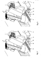
- eine perspektivische Ansicht einer Ausführungsform der erfindungsgemäßen Vorrichtung in teilweise aufgebrochener Darstellung;
- Fig. 2
- eine Detailansicht des Bearbeitungskopfes der erfindungsgemäßen Vorrichtung aus
Fig. 1 , wobei die Vorschubvorrichtung eine Ruhestellung einnimmt, in der sie nicht am Sägewerkzeug angreift; und - Fig. 3
- eine Detailansicht analog zu
Fig. 2 , wobei die Vorschubvorrichtung eine Mitnahmestellung einnimmt, in der sie in das Verzahnungsprofil des Sägewerkzeugs eingreift.
- Fig. 1
- a perspective view of an embodiment of the device according to the invention in a partially broken view;
- Fig. 2
- a detailed view of the machining head of the device according to the invention
Fig. 1 wherein the advancing device assumes a rest position in which it does not attack the sawing tool; and - Fig. 3
- a detailed view analogous to
Fig. 2 , wherein the feed device assumes a driving position, in which it engages in the tooth profile of the sawing tool.
In
Die Vorrichtung 10 weist weiterhin einen Bearbeitungskopf 20 auf. Dieser umfasst eine Rotationsachse R, die vorgesehen ist, um ein Rotationswerkzeug 22 anzutreiben, in diesem Fall eine Schleifscheibe. Die Rotationsachse R und das Rotationswerkzeug 22 sind derart an einer Hubachse H angeordnet, dass das Rotationswerkzeug 22 relativ zum Maschinenbett 12 höhenverstellbar ist. Die Hubachse H ist wiederum mittels einer Schwenkachse S relativ zum Maschinenbett 12 verschwenkbar. Die Schwenkachse S ist an einer linearen Bewegungsachse L angeordnet, mittels welcher der Bearbeitungskopf 20 längs des Maschinenbetts 12 verlagerbar ist.The
Der Arbeitsraum der Vorrichtung 10 ist von einem Maschinengehäuse 24 umgeben, welches einen öffnungsfähigen Abschnitt 26 aufweist. Dieser Abschnitt 26 ist in an sich bekannter Weise relativ zum Maschinengehäuse 24 verschwenkbar oder klappbar, so dass insbesondere Bandsägeblätter von in
Außerhalb des Maschinenraums der Vorrichtung 10 wird das Sägewerkzeug 14 durch nicht dargestellte, an sich bekannte Stützvorrichtungen gehalten und geführt, insbesondere im nicht gezeigten hinteren Teil der Vorrichtung 10.Outside the machine room of the
In
Wie man in
Wie in
Weiterhin erkennt man aus den
Im Folgenden wird bezugnehmend auf die vorstehend beschriebenen Figuren eine bevorzugte Variante des erfindungsgemäßen Verfahrens zum Bearbeiten eines Sägewerkzeugs mit der erfindungsgemäßen Vorrichtung erläutert.In the following, a preferred variant of the method according to the invention for processing a sawing tool with the device according to the invention is explained with reference to the figures described above.
Zunächst wird das Sägewerkzeug 14 in bekannter Weise von in
Beim Erreichen der maximal ausgelenkten Stellung des Bearbeitungskopfes 20, also dem in
Es gilt anzumerken, dass das Bearbeiten eines Sägwerkzeugs mittels der gezeigten Vorrichtung 10 auch durch Bewegen des Bearbeitungskopfes 20 in entgegengesetzter Richtung erfolgen kann, also vom in
Die vorstehend beschriebenen Verfahrensschritte werden zumindest so oft wiederholt, bis das Sägewerkzeug 14 an jedem Zahn oder an bestimmten ausgewählten Zähnen bearbeitet wurde. Das Vorgeben der Bearbeitungslänge B erfolgt dabei derart, dass die Anzahl der Durchläufe der einzelnen Verfahrensschritte minimiert wird. Entsprechend weist die Bearbeitungslänge B einen möglichst großen Wert auf, dessen Maximallänge durch die Maschinenstruktur vorgesehen ist. Umfasst das Sägewerkzeug eine Anzahl von Zähnen, die nicht einem ganzzahligen Vielfachen der von der Bearbeitungslänge B eingeschlossenen Anzahl von Zähnen entspricht, so wird bei einem der für das Bearbeiten notwendigen Durchläufe der vorstehend beschriebenen Verfahrensschritte die Bearbeitungslänge B entsprechend der verbleibenden Restanzahl an Zähnen angepasst.The process steps described above are repeated at least until the
Claims (17)
- A device (10) for sharpening of elongated saw tools (14), comprising- a base which comprises an elongated machine bed (12);- a fixing device which is adapted to fix the saw tool (14) to be machined relative to the machine bed (12);- a machining head (20) with an axis of rotation (R) for driving a rotating tool (22) and a lift axle (H) for height adjustment of the rotating tool (22) relative to the machine bed (12);characterised in that
the machining head (20) may by shifted along the machine bed (12) by means of a linear movement axle (L) in such a manner that a fixed saw tool (14) may be machined along a predetermined machining length (B) which comprises a plurality of teeth, and
a feed device (28) is provided which is adapted to optionally shift the saw tool (14) along the machine bed (12) by the distance of a single tooth or a tooth pitch, respectively, or by the distance of a predetermined machining length (B) which comprises a plurality of teeth. - The device (10) according to Claim 1,
characterised in that the feed device (28) may be optionally shifted along the machine bed (12) by the distance of a single tooth or by the distance of the predetermined machining length (B) which comprises a plurality of teeth. - The device (10) according to Claim 2,
characterised in that the feed device (28) may be shifted along the machine bed (12) by means of a separately provided movement axle (L). - The device (10) according to Claim 4,
characterised in that the feed device (28) is arranged at the machining head (20) so that it may be shifted together with same by means of the linear movement axle (L). - The device (10) according to one of the previous claims,
characterised in that the feed device (28) acts on the saw tool (14) under frictional connection in order to shift it. - The device (10) according to one of Claims 1 to 4,
characterised in that the feed device (28) acts on the saw tool (14) under positive locking in order to shift it. - The device (10) according to Claim 5 or 6,
characterised in that the feed device (28) comprises a driving finger (30) which is movable from a rest position into a driving position in which it comes into contact with the saw tool (14) in order to shift it. - The device (10) according to Claim 7,
characterised in that the movement of the driving finger (30) into the driving position is effected by means of a separate movement axle. - The device (10) according to one of Claims 7 or 8,
characterised in that the driving finger (30) is adapted in such a manner that it is movable into its driving position transversely to the longitudinal axis of the machine bed (12). - The device (10) according to one of the previous claims,
characterised in that the feed device (28) acts essentially on the same area of the saw tool as the rotary tool (22) in order to shift the saw tool. - The device (10) according to one of the previous claims,
characterised in that the machining head (20) comprises a pivot axle (S) for pivoting the rotary tool (22) relative to the machine bed (12). - The device (10) according to Claim 11,
characterised in that the feed device (28) is arranged at the machining head (20) in such a manner that it may be pivoted together with the rotary tool (22) by means of the pivot axle (S). - The device (10) according to Claim 11 or 12,
characterised in that the pivot axle (S) is arranged in such a manner that it pivots the rotary tool (22) about a horizontal spatial axis which is arranged essentially orthogonally to the longitudinal axis of the machine bed (12). - The device (10) according to one of the previous claims,
characterised in that the feed device (28) may be controlled by means of a CNC controller. - A method for sharpening of elongated saw tools (14) with a device (10) according to one of the previous claims, characterised by the steps:a) Specifying the movements to be performed by the pivot axle (S) and the lift axle (H) depending on a saw tool (14) to be machined;b) specifying the movements to be performed by the linear movement axle (L) depending on a machining length (B) to be covered which comprises a plurality of teeth;c) machining of the saw tool (14) along the machining length (B);d) returning of the machining head (20) by the distance of the covered machining length (B) by means of the linear movement axle (L);e) shifting of the saw tool (14) along the machine bed (12) by the distance of the machining length (B) by means of the feed device (28).
- The method according to Claim 15,
characterised in that steps a) to e) are repeated at least as often until each tooth of the saw tool (14) was machined once. - The method according to Claim 16,
wherein steps a) and b) are only performed again in the repetition of the method steps if the movements of the axles differ from those of the previous cycle.
Applications Claiming Priority (1)
| Application Number | Priority Date | Filing Date | Title |
|---|---|---|---|
| DE102013005593.8A DE102013005593A1 (en) | 2013-04-03 | 2013-04-03 | Apparatus for selectively sharpening band and gang saw blades |
Publications (2)
| Publication Number | Publication Date |
|---|---|
| EP2786823A1 EP2786823A1 (en) | 2014-10-08 |
| EP2786823B1 true EP2786823B1 (en) | 2015-06-24 |
Family
ID=50440441
Family Applications (1)
| Application Number | Title | Priority Date | Filing Date |
|---|---|---|---|
| EP14001244.4A Not-in-force EP2786823B1 (en) | 2013-04-03 | 2014-04-03 | Device for optional sharpening of ribbon and gang saw blades |
Country Status (2)
| Country | Link |
|---|---|
| EP (1) | EP2786823B1 (en) |
| DE (1) | DE102013005593A1 (en) |
Families Citing this family (1)
| Publication number | Priority date | Publication date | Assignee | Title |
|---|---|---|---|---|
| EP3974089B1 (en) | 2020-09-23 | 2023-06-07 | Kohlbacher GmbH | Device and method for sharpening bandsaw blades which cut on both sides |
Family Cites Families (8)
| Publication number | Priority date | Publication date | Assignee | Title |
|---|---|---|---|---|
| US1327012A (en) * | 1918-12-10 | 1920-01-06 | Asmondis Rocco | Saw-sharpening machine |
| US2305564A (en) * | 1941-10-22 | 1942-12-15 | Ralph E Tubbs | Saw filing device |
| US2462225A (en) * | 1947-01-31 | 1949-02-22 | Arthur R Roderick | Saw filing machine |
| US5488884A (en) * | 1994-04-07 | 1996-02-06 | Armstrong Manufacturing Company | Method and apparatus for side-grinding saw blade teeth |
| DE19518710C1 (en) | 1995-05-22 | 1996-11-28 | Vollmer Werke Maschf | Device for path-controlled sharpening of saw teeth |
| GB9510275D0 (en) | 1995-05-22 | 1995-07-19 | Iseli & Co Ag | Saw blade tooth formation |
| WO2002057043A1 (en) * | 2000-12-22 | 2002-07-25 | Pacific/Hoe Saw & Knife Company | Saw sharpening machine with pitch pre-measurement and feedback control for saw blade indexing |
| DE10351151B3 (en) * | 2003-11-03 | 2005-06-09 | Vollmer Werke Maschinenfabrik Gmbh | Grinding machine for bandsaw blade has common central machine block provided with machining device, displacement device, workpiece fixing device and workpiece guidance device |
-
2013
- 2013-04-03 DE DE102013005593.8A patent/DE102013005593A1/en not_active Withdrawn
-
2014
- 2014-04-03 EP EP14001244.4A patent/EP2786823B1/en not_active Not-in-force
Also Published As
| Publication number | Publication date |
|---|---|
| EP2786823A1 (en) | 2014-10-08 |
| DE102013005593A1 (en) | 2014-10-09 |
Similar Documents
| Publication | Publication Date | Title |
|---|---|---|
| EP0161400B1 (en) | Method of dentistry and device for bending a piece of wire and subjecting it to a torsional stress | |
| EP1982799B1 (en) | Handling device | |
| EP2732895B1 (en) | Machine tool for manufacturing profiles | |
| EP0654318A1 (en) | Machine for finishing the tooth flanks of gear-shaped workpieces using an internally toothed tool | |
| DE202010008628U1 (en) | Device for processing elongated, non-rotationally symmetrical components, in particular turbine blades | |
| DE102009023275A1 (en) | gear cutting | |
| DE60224682T2 (en) | Machine for processing wooden parts or the like | |
| DE102017112450A1 (en) | Apparatus and method for chamfering an internally toothed workpiece | |
| DE102009019267A1 (en) | 4-axis machine tool | |
| EP2926943B1 (en) | Profile machining device and method for machining profiles | |
| WO2018055190A1 (en) | Method, machine tool, and slotting tool for the multiple-stroke slotting of plate-shaped workpieces | |
| DE102017121526A1 (en) | Device for aligning and positioning a workpiece relative to a laser beam of a laser processing machine | |
| EP2944390B1 (en) | Bending tool and method for changing tool | |
| DE2625804A1 (en) | MACHINE FOR MILLING GEAR TOOTH GAPS | |
| EP2786823B1 (en) | Device for optional sharpening of ribbon and gang saw blades | |
| DE102016120139B4 (en) | Method, machine tool and slot tool for multi-stroke progressive slitting of plate-shaped workpieces | |
| DE102013200851B4 (en) | Bending device for strand-shaped workpieces | |
| DE60114695T2 (en) | Wringer and follower tool with such device | |
| EP1541270B1 (en) | Machine for dressing band saw blades | |
| EP3199369B1 (en) | Method of preforming and rounding a book block | |
| EP2832485A2 (en) | Gear cutting machine | |
| EP0395628A2 (en) | Machining device for working the inner wall of an underground channel profile, in particular when non-circular | |
| DE102004013825B4 (en) | articulated arm | |
| DE7920030U1 (en) | CHIPPING MACHINE TOOL | |
| DE3007965A1 (en) | MACHINE FOR SHARPENING ROOM NEEDLES |
Legal Events
| Date | Code | Title | Description |
|---|---|---|---|
| PUAI | Public reference made under article 153(3) epc to a published international application that has entered the european phase |
Free format text: ORIGINAL CODE: 0009012 |
|
| 17P | Request for examination filed |
Effective date: 20140403 |
|
| AK | Designated contracting states |
Kind code of ref document: A1 Designated state(s): AL AT BE BG CH CY CZ DE DK EE ES FI FR GB GR HR HU IE IS IT LI LT LU LV MC MK MT NL NO PL PT RO RS SE SI SK SM TR |
|
| AX | Request for extension of the european patent |
Extension state: BA ME |
|
| R17P | Request for examination filed (corrected) |
Effective date: 20141211 |
|
| RBV | Designated contracting states (corrected) |
Designated state(s): AL AT BE BG CH CY CZ DE DK EE ES FI FR GB GR HR HU IE IS IT LI LT LU LV MC MK MT NL NO PL PT RO RS SE SI SK SM TR |
|
| GRAP | Despatch of communication of intention to grant a patent |
Free format text: ORIGINAL CODE: EPIDOSNIGR1 |
|
| INTG | Intention to grant announced |
Effective date: 20150129 |
|
| GRAS | Grant fee paid |
Free format text: ORIGINAL CODE: EPIDOSNIGR3 |
|
| GRAA | (expected) grant |
Free format text: ORIGINAL CODE: 0009210 |
|
| AK | Designated contracting states |
Kind code of ref document: B1 Designated state(s): AL AT BE BG CH CY CZ DE DK EE ES FI FR GB GR HR HU IE IS IT LI LT LU LV MC MK MT NL NO PL PT RO RS SE SI SK SM TR |
|
| REG | Reference to a national code |
Ref country code: GB Ref legal event code: FG4D Free format text: NOT ENGLISH |
|
| REG | Reference to a national code |
Ref country code: CH Ref legal event code: EP |
|
| REG | Reference to a national code |
Ref country code: AT Ref legal event code: REF Ref document number: 732685 Country of ref document: AT Kind code of ref document: T Effective date: 20150715 |
|
| REG | Reference to a national code |
Ref country code: IE Ref legal event code: FG4D Free format text: LANGUAGE OF EP DOCUMENT: GERMAN |
|
| REG | Reference to a national code |
Ref country code: DE Ref legal event code: R096 Ref document number: 502014000031 Country of ref document: DE |
|
| PG25 | Lapsed in a contracting state [announced via postgrant information from national office to epo] |
Ref country code: LT Free format text: LAPSE BECAUSE OF FAILURE TO SUBMIT A TRANSLATION OF THE DESCRIPTION OR TO PAY THE FEE WITHIN THE PRESCRIBED TIME-LIMIT Effective date: 20150624 Ref country code: HR Free format text: LAPSE BECAUSE OF FAILURE TO SUBMIT A TRANSLATION OF THE DESCRIPTION OR TO PAY THE FEE WITHIN THE PRESCRIBED TIME-LIMIT Effective date: 20150624 Ref country code: NO Free format text: LAPSE BECAUSE OF FAILURE TO SUBMIT A TRANSLATION OF THE DESCRIPTION OR TO PAY THE FEE WITHIN THE PRESCRIBED TIME-LIMIT Effective date: 20150924 Ref country code: FI Free format text: LAPSE BECAUSE OF FAILURE TO SUBMIT A TRANSLATION OF THE DESCRIPTION OR TO PAY THE FEE WITHIN THE PRESCRIBED TIME-LIMIT Effective date: 20150624 |
|
| REG | Reference to a national code |
Ref country code: LT Ref legal event code: MG4D |
|
| PG25 | Lapsed in a contracting state [announced via postgrant information from national office to epo] |
Ref country code: GR Free format text: LAPSE BECAUSE OF FAILURE TO SUBMIT A TRANSLATION OF THE DESCRIPTION OR TO PAY THE FEE WITHIN THE PRESCRIBED TIME-LIMIT Effective date: 20150925 Ref country code: LV Free format text: LAPSE BECAUSE OF FAILURE TO SUBMIT A TRANSLATION OF THE DESCRIPTION OR TO PAY THE FEE WITHIN THE PRESCRIBED TIME-LIMIT Effective date: 20150624 Ref country code: BG Free format text: LAPSE BECAUSE OF FAILURE TO SUBMIT A TRANSLATION OF THE DESCRIPTION OR TO PAY THE FEE WITHIN THE PRESCRIBED TIME-LIMIT Effective date: 20150924 Ref country code: RS Free format text: LAPSE BECAUSE OF FAILURE TO SUBMIT A TRANSLATION OF THE DESCRIPTION OR TO PAY THE FEE WITHIN THE PRESCRIBED TIME-LIMIT Effective date: 20150624 |
|
| REG | Reference to a national code |
Ref country code: NL Ref legal event code: MP Effective date: 20150624 |
|
| PG25 | Lapsed in a contracting state [announced via postgrant information from national office to epo] |
Ref country code: EE Free format text: LAPSE BECAUSE OF FAILURE TO SUBMIT A TRANSLATION OF THE DESCRIPTION OR TO PAY THE FEE WITHIN THE PRESCRIBED TIME-LIMIT Effective date: 20150624 |
|
| PG25 | Lapsed in a contracting state [announced via postgrant information from national office to epo] |
Ref country code: SK Free format text: LAPSE BECAUSE OF FAILURE TO SUBMIT A TRANSLATION OF THE DESCRIPTION OR TO PAY THE FEE WITHIN THE PRESCRIBED TIME-LIMIT Effective date: 20150624 Ref country code: CZ Free format text: LAPSE BECAUSE OF FAILURE TO SUBMIT A TRANSLATION OF THE DESCRIPTION OR TO PAY THE FEE WITHIN THE PRESCRIBED TIME-LIMIT Effective date: 20150624 Ref country code: IS Free format text: LAPSE BECAUSE OF FAILURE TO SUBMIT A TRANSLATION OF THE DESCRIPTION OR TO PAY THE FEE WITHIN THE PRESCRIBED TIME-LIMIT Effective date: 20151024 Ref country code: ES Free format text: LAPSE BECAUSE OF FAILURE TO SUBMIT A TRANSLATION OF THE DESCRIPTION OR TO PAY THE FEE WITHIN THE PRESCRIBED TIME-LIMIT Effective date: 20150624 Ref country code: PT Free format text: LAPSE BECAUSE OF FAILURE TO SUBMIT A TRANSLATION OF THE DESCRIPTION OR TO PAY THE FEE WITHIN THE PRESCRIBED TIME-LIMIT Effective date: 20151026 Ref country code: RO Free format text: LAPSE BECAUSE OF NON-PAYMENT OF DUE FEES Effective date: 20150624 Ref country code: PL Free format text: LAPSE BECAUSE OF FAILURE TO SUBMIT A TRANSLATION OF THE DESCRIPTION OR TO PAY THE FEE WITHIN THE PRESCRIBED TIME-LIMIT Effective date: 20150624 |
|
| REG | Reference to a national code |
Ref country code: DE Ref legal event code: R097 Ref document number: 502014000031 Country of ref document: DE |
|
| PG25 | Lapsed in a contracting state [announced via postgrant information from national office to epo] |
Ref country code: DK Free format text: LAPSE BECAUSE OF FAILURE TO SUBMIT A TRANSLATION OF THE DESCRIPTION OR TO PAY THE FEE WITHIN THE PRESCRIBED TIME-LIMIT Effective date: 20150624 |
|
| PLBE | No opposition filed within time limit |
Free format text: ORIGINAL CODE: 0009261 |
|
| STAA | Information on the status of an ep patent application or granted ep patent |
Free format text: STATUS: NO OPPOSITION FILED WITHIN TIME LIMIT |
|
| 26N | No opposition filed |
Effective date: 20160329 |
|
| PG25 | Lapsed in a contracting state [announced via postgrant information from national office to epo] |
Ref country code: BE Free format text: LAPSE BECAUSE OF NON-PAYMENT OF DUE FEES Effective date: 20160430 Ref country code: SI Free format text: LAPSE BECAUSE OF FAILURE TO SUBMIT A TRANSLATION OF THE DESCRIPTION OR TO PAY THE FEE WITHIN THE PRESCRIBED TIME-LIMIT Effective date: 20150624 |
|
| PG25 | Lapsed in a contracting state [announced via postgrant information from national office to epo] |
Ref country code: LU Free format text: LAPSE BECAUSE OF FAILURE TO SUBMIT A TRANSLATION OF THE DESCRIPTION OR TO PAY THE FEE WITHIN THE PRESCRIBED TIME-LIMIT Effective date: 20160403 |
|
| REG | Reference to a national code |
Ref country code: IE Ref legal event code: MM4A |
|
| REG | Reference to a national code |
Ref country code: FR Ref legal event code: ST Effective date: 20161230 |
|
| PG25 | Lapsed in a contracting state [announced via postgrant information from national office to epo] |
Ref country code: FR Free format text: LAPSE BECAUSE OF NON-PAYMENT OF DUE FEES Effective date: 20160502 |
|
| PG25 | Lapsed in a contracting state [announced via postgrant information from national office to epo] |
Ref country code: IE Free format text: LAPSE BECAUSE OF NON-PAYMENT OF DUE FEES Effective date: 20160403 |
|
| PG25 | Lapsed in a contracting state [announced via postgrant information from national office to epo] |
Ref country code: NL Free format text: LAPSE BECAUSE OF FAILURE TO SUBMIT A TRANSLATION OF THE DESCRIPTION OR TO PAY THE FEE WITHIN THE PRESCRIBED TIME-LIMIT Effective date: 20150624 Ref country code: SE Free format text: LAPSE BECAUSE OF FAILURE TO SUBMIT A TRANSLATION OF THE DESCRIPTION OR TO PAY THE FEE WITHIN THE PRESCRIBED TIME-LIMIT Effective date: 20150624 |
|
| PG25 | Lapsed in a contracting state [announced via postgrant information from national office to epo] |
Ref country code: SM Free format text: LAPSE BECAUSE OF FAILURE TO SUBMIT A TRANSLATION OF THE DESCRIPTION OR TO PAY THE FEE WITHIN THE PRESCRIBED TIME-LIMIT Effective date: 20150624 Ref country code: HU Free format text: LAPSE BECAUSE OF FAILURE TO SUBMIT A TRANSLATION OF THE DESCRIPTION OR TO PAY THE FEE WITHIN THE PRESCRIBED TIME-LIMIT; INVALID AB INITIO Effective date: 20140403 |
|
| PG25 | Lapsed in a contracting state [announced via postgrant information from national office to epo] |
Ref country code: CY Free format text: LAPSE BECAUSE OF FAILURE TO SUBMIT A TRANSLATION OF THE DESCRIPTION OR TO PAY THE FEE WITHIN THE PRESCRIBED TIME-LIMIT Effective date: 20150624 Ref country code: MK Free format text: LAPSE BECAUSE OF FAILURE TO SUBMIT A TRANSLATION OF THE DESCRIPTION OR TO PAY THE FEE WITHIN THE PRESCRIBED TIME-LIMIT Effective date: 20150624 Ref country code: MT Free format text: LAPSE BECAUSE OF FAILURE TO SUBMIT A TRANSLATION OF THE DESCRIPTION OR TO PAY THE FEE WITHIN THE PRESCRIBED TIME-LIMIT Effective date: 20150624 Ref country code: MC Free format text: LAPSE BECAUSE OF FAILURE TO SUBMIT A TRANSLATION OF THE DESCRIPTION OR TO PAY THE FEE WITHIN THE PRESCRIBED TIME-LIMIT Effective date: 20150624 |
|
| PG25 | Lapsed in a contracting state [announced via postgrant information from national office to epo] |
Ref country code: TR Free format text: LAPSE BECAUSE OF FAILURE TO SUBMIT A TRANSLATION OF THE DESCRIPTION OR TO PAY THE FEE WITHIN THE PRESCRIBED TIME-LIMIT Effective date: 20150624 Ref country code: AL Free format text: LAPSE BECAUSE OF FAILURE TO SUBMIT A TRANSLATION OF THE DESCRIPTION OR TO PAY THE FEE WITHIN THE PRESCRIBED TIME-LIMIT Effective date: 20150624 |
|
| GBPC | Gb: european patent ceased through non-payment of renewal fee |
Effective date: 20180403 |
|
| PG25 | Lapsed in a contracting state [announced via postgrant information from national office to epo] |
Ref country code: GB Free format text: LAPSE BECAUSE OF NON-PAYMENT OF DUE FEES Effective date: 20180403 |
|
| REG | Reference to a national code |
Ref country code: CH Ref legal event code: NV Representative=s name: SCHNEIDER FELDMANN AG PATENT- UND MARKENANWAEL, CH Ref country code: CH Ref legal event code: PUE Owner name: ISELI AND CO. AG MASCHINENFABRIK, CH Free format text: FORMER OWNER: VOLLMER WERKE MASCHINENFABRIK GMBH, DE |
|
| REG | Reference to a national code |
Ref country code: DE Ref legal event code: R082 Ref document number: 502014000031 Country of ref document: DE Representative=s name: WUESTHOFF & WUESTHOFF, PATENTANWAELTE PARTG MB, DE Ref country code: DE Ref legal event code: R081 Ref document number: 502014000031 Country of ref document: DE Owner name: ISELI & CO. AG MASCHINENFABRIK, CH Free format text: FORMER OWNER: VOLLMER WERKE MASCHINENFABRIK GMBH, 88400 BIBERACH, DE |
|
| PGFP | Annual fee paid to national office [announced via postgrant information from national office to epo] |
Ref country code: DE Payment date: 20200325 Year of fee payment: 7 |
|
| REG | Reference to a national code |
Ref country code: AT Ref legal event code: MM01 Ref document number: 732685 Country of ref document: AT Kind code of ref document: T Effective date: 20190403 |
|
| PGFP | Annual fee paid to national office [announced via postgrant information from national office to epo] |
Ref country code: IT Payment date: 20200312 Year of fee payment: 7 |
|
| REG | Reference to a national code |
Ref country code: CH Ref legal event code: PFA Owner name: ISELI AND CO. AG MASCHINENFABRIK, CH Free format text: FORMER OWNER: ISELI AND CO. AG MASCHINENFABRIK, CH |
|
| PG25 | Lapsed in a contracting state [announced via postgrant information from national office to epo] |
Ref country code: AT Free format text: LAPSE BECAUSE OF NON-PAYMENT OF DUE FEES Effective date: 20190403 |
|
| PGFP | Annual fee paid to national office [announced via postgrant information from national office to epo] |
Ref country code: CH Payment date: 20200727 Year of fee payment: 7 |
|
| REG | Reference to a national code |
Ref country code: DE Ref legal event code: R119 Ref document number: 502014000031 Country of ref document: DE |
|
| PG25 | Lapsed in a contracting state [announced via postgrant information from national office to epo] |
Ref country code: DE Free format text: LAPSE BECAUSE OF NON-PAYMENT OF DUE FEES Effective date: 20211103 Ref country code: LI Free format text: LAPSE BECAUSE OF NON-PAYMENT OF DUE FEES Effective date: 20210430 Ref country code: CH Free format text: LAPSE BECAUSE OF NON-PAYMENT OF DUE FEES Effective date: 20210430 |
|
| PG25 | Lapsed in a contracting state [announced via postgrant information from national office to epo] |
Ref country code: IT Free format text: LAPSE BECAUSE OF NON-PAYMENT OF DUE FEES Effective date: 20200403 |