EP1692493B1 - Fiber optic device for sensing analytes - Google Patents
Fiber optic device for sensing analytes Download PDFInfo
- Publication number
- EP1692493B1 EP1692493B1 EP04820029A EP04820029A EP1692493B1 EP 1692493 B1 EP1692493 B1 EP 1692493B1 EP 04820029 A EP04820029 A EP 04820029A EP 04820029 A EP04820029 A EP 04820029A EP 1692493 B1 EP1692493 B1 EP 1692493B1
- Authority
- EP
- European Patent Office
- Prior art keywords
- optical
- glucose
- sensing element
- ggbp
- optical system
- Prior art date
- Legal status (The legal status is an assumption and is not a legal conclusion. Google has not performed a legal analysis and makes no representation as to the accuracy of the status listed.)
- Not-in-force
Links
Images


Classifications
-
- G—PHYSICS
- G01—MEASURING; TESTING
- G01N—INVESTIGATING OR ANALYSING MATERIALS BY DETERMINING THEIR CHEMICAL OR PHYSICAL PROPERTIES
- G01N21/00—Investigating or analysing materials by the use of optical means, i.e. using sub-millimetre waves, infrared, visible or ultraviolet light
- G01N21/75—Systems in which material is subjected to a chemical reaction, the progress or the result of the reaction being investigated
- G01N21/77—Systems in which material is subjected to a chemical reaction, the progress or the result of the reaction being investigated by observing the effect on a chemical indicator
- G01N21/7703—Systems in which material is subjected to a chemical reaction, the progress or the result of the reaction being investigated by observing the effect on a chemical indicator using reagent-clad optical fibres or optical waveguides
-
- G—PHYSICS
- G01—MEASURING; TESTING
- G01N—INVESTIGATING OR ANALYSING MATERIALS BY DETERMINING THEIR CHEMICAL OR PHYSICAL PROPERTIES
- G01N33/00—Investigating or analysing materials by specific methods not covered by groups G01N1/00 - G01N31/00
- G01N33/48—Biological material, e.g. blood, urine; Haemocytometers
- G01N33/50—Chemical analysis of biological material, e.g. blood, urine; Testing involving biospecific ligand binding methods; Immunological testing
- G01N33/53—Immunoassay; Biospecific binding assay; Materials therefor
- G01N33/536—Immunoassay; Biospecific binding assay; Materials therefor with immune complex formed in liquid phase
- G01N33/542—Immunoassay; Biospecific binding assay; Materials therefor with immune complex formed in liquid phase with steric inhibition or signal modification, e.g. fluorescent quenching
-
- G—PHYSICS
- G01—MEASURING; TESTING
- G01N—INVESTIGATING OR ANALYSING MATERIALS BY DETERMINING THEIR CHEMICAL OR PHYSICAL PROPERTIES
- G01N33/00—Investigating or analysing materials by specific methods not covered by groups G01N1/00 - G01N31/00
- G01N33/48—Biological material, e.g. blood, urine; Haemocytometers
- G01N33/50—Chemical analysis of biological material, e.g. blood, urine; Testing involving biospecific ligand binding methods; Immunological testing
- G01N33/53—Immunoassay; Biospecific binding assay; Materials therefor
- G01N33/543—Immunoassay; Biospecific binding assay; Materials therefor with an insoluble carrier for immobilising immunochemicals
- G01N33/54366—Apparatus specially adapted for solid-phase testing
- G01N33/54373—Apparatus specially adapted for solid-phase testing involving physiochemical end-point determination, e.g. wave-guides, FETS, gratings
Definitions
- the present invention relates to a device that can be used to monitor concentrations of physiologically relevant compounds.
- Non-invasive monitoring determines analyte levels by directly tracking spectroscopic changes in skin and tissue. Infrared radiation and radio wave impedance spectroscopy are examples of this technology. Progress with these approaches has been slow due to the requirement for frequent calibration, reproducible sample illumination, and variances in spectroscopic backgrounds between individuals.
- the “minimally invasive” approach avoids direct extraction of blood from the body and relies on the monitoring of signal changes in biological fluids using an intermediate sensing element.
- Biosensors of this type are devices capable of providing specific quantitative or semi-quantitative analytical information using a biological recognition element that is combined with a transducing (detecting) element.
- Biosensors based on optical rather than electrochemical signals have also been developed and may offer significant improvements in stability and calibration. For example, referencing an analyte-dependent optical signal against a second analyte-independent signal can correct for sources of noise and instability in the sensor.
- the potential of optical sensing for in vivo analyte detection has not yet been realized.
- One reason for this is that many current optical sensing methods rely on enzymatic chemistry such as glucose oxidase.
- an oxygen-sensitive fluorescent dye is used to monitor the consumption of oxygen by the GOx enzymatic reaction.
- this is an optical biosensor, with the fluorescence signal level varying with changing oxygen levels, such a sensor is subject to the same problems as amperometric devices based on this same chemistry: oxygen deficiency and enzyme degradation.
- E. coli Escherichia coli
- GGBP glucose-galactose binding protein
- GGBP GGBP-binding protein-binding protein-binding protein
- binding proteins require orientational control and conformational freedom to enable effective use, many physical absorption and random or bulk covalent surface attachment or immobilization strategies as taught in the literature generally are either suboptimal or unsuccessful. Further, a means for interrogating the sample with light in a reproducible and/or controlled fashion must be devised.
- One approach generally known is to couple the sensing element to one end of an optical fiber and to couple the optical elements such as excitation sources or detectors to the other end.
- coupling of binding proteins to one end of an optical fiber is subject to the above-mentioned challenge of preserving conformational and/or orientational mobility of the protein.
- fiber optic cabling is often impractical from a patient-use point of view since patients may need to remove or replace the sensor periodically. Replacement of the entire fiber can be costly and inconvenient.
- the optical system comprising, e.g., excitation sources, detectors, and other optical elements must be sufficiently robust to tolerate or correct for changes in optical alignment due, for example, to patient motion or drift of the electronics in the optical reader.
- the optical system must also be sufficiently sensitive to detect signal from reporter dyes without relying on high power consumption and/or large-sized elements that would render the system unportable and hence unwearable.
- biosensor that incorporates in its sensing element a binding protein with conformational and/or orientational mobility coupled to optical sensing elements that provide a wearable and robust device.
- WO03057734 discloses a biosensor immobilised into a dialysis membrane matrix which provides reversible and continuous readings.
- GGBP L238C/A213C protein (2 uM in PBS buffer) entrapped with the dialysis membrane having a molecular cut-off of 3500 Daltons is affixed to the distal end of the fiber.
- the fluorescent reporter may be e.g. IANBD which may be attached to the mutated protein such as GGBPs.
- the biosensor may be used for analyte sensing in vivo as an implantable device and is encapsulated into a matrix which may be a porous polymer derived substantially from a hydrogel for example, polysaccharides such as agarose, dextran, carrageenan and alginic acid.
- a matrix which may be a porous polymer derived substantially from a hydrogel for example, polysaccharides such as agarose, dextran, carrageenan and alginic acid.
- An object of the present invention is to provide a device for sensing the concentration of glucose in a sample.
- the sample may be blood, saliva, tears, sweat, urine, cerebral spinal fluid, lymph fluid interstitial fluid, plasma, serum, animal tissue and media.
- the device for sensing glucose in a sample comprises:
- the optical silica fiber which may vary in length from approximately 0.1 cm to 1 meter, couples light into and out of the optical system and into and out of the sensing element.
- the optical silica fiber may be either a single strand of optical fiber (single or multimode) or a bundle of more than one fiber. In one embodiment, the bundle of fibers is bifurcated.
- the fiber may be non-tapered or tapered so that it can penetrate the skin of a patient.
- the optical system consists of a combination of one or more excitation sources and one or more detectors. It may also consist of filters, dichroic elements, a power supply, and electronics for signal detection and modulation.
- the optical system may optionally include a microprocessor.
- the optical system interrogates the sample either continuously or intermittently by coupling one or more interrogating wavelengths of light into the optical silica fiber.
- the one or more interrogating wavelengths then pass through the optical silica fiber and illuminate the sensing element.
- a change in analyte concentration results in a change of the wavelength, intensity, lifetime, energy transfer efficiency, and/or polarization of the luminescence of the reporter group, which is a part of the sensing element.
- the resulting changed luminescence signal passes back through the optical conduit to the optical system where it is detected, interpreted, and stored and/or displayed.
- the optical system comprises multiple excitation sources.
- One or more of these sources may be modulated to permit dynamic signal processing of the detected signal, thereby enhancing signal-to-noise and detection sensitivity. Modulation may also be used to reduce power consumption by the device or to increase the lifetime of the sensing element by minimizing undesirable phenomena such as photobleaching.
- the optical system can also include one or more electromagnetic energy detectors that can be used for detecting the luminescence signal from the reporter and optional reference groups as well as for internal referencing and/or calibration. The overall power consumption of the optical system is kept small to permit the device to be operated using battery power.
- the sensing element comprises at least one GGBP adapted to bind with glucose, and at least one reporter group.
- GGBP may be any one of those described in WO 03/057851 , WO 03/057734 and may also be any one of those described in U.S. Patent No. 6,277,627 , U.S. Patent No. 6197534 , or WO 03/060464 A2 .
- the reporter group which is associated with the GGBP, is adapted to undergo a luminescence change upon binding of the GGBP to the glucose.
- the term "associated with” means that the reporter group is covalently or non-covalently associated with the GGBP such that upon binding of glucose to the GGBP, there is a change in the reporter group's luminescence properties such as wavelength, intensity, lifetime, energy transfer efficiency, and/or polarization.
- reporter groups include organic dyes, pairs of organic dyes, fluorescent or bioluminescent fusion proteins, pairs of fluorescent or bioluminescent fusion proteins, or any combination of the above.
- the reporter group may consist of a donor and acceptor undergoing fluorescence resonance energy transfer.
- luminescent labeling moieties include lanthanides such as europium (Eu3+) and terbium (Tb3+), as well as metal-ligand complexes, including those of ruthenium [Ru (II)], rhenium [Re(I)], or osmium [Os (II)] , typically in complexes with diimine ligands such as phenanthrolines.
- the sensing element is in optical proximity to the optical silica fiber.
- Optical proximity means that components of the device are close enough to one another such that an optical signal can be transmitted to or received from one object by another.
- the sensing element as defined above is placed in optical proximity to the optical silica fiber as defined above.
- the sensing element is permanently affixed to the optical silca fiber.
- the sensing element may further comprise one or more reference groups.
- the reference group has a luminescence signal that is substantially unchanged upon binding of the glucose to the GGBP. "Substantially unchanged” means the luminescence change of the reference group is significantly less than the luminescence change undergone by the reporter group.
- the reference group which can consist of luminescent dyes and/or proteins, is used for internal referencing and calibration.
- the reference group can be attached to any number of components of the device including the sensing element, a GGBP not containing the reporter group, the alginale matrix, a biomolecule that is not a GGBP, the optical silica fiber, or a needle.
- the sensing element (typically this refers to the GGBP with the associated reporter group and optional reference group) is attached directly to the distal end of the optical silica fiber using covalent interactions.
- the GGBP and the reporter group are attached to or immobilized in the alginate matrix.
- the alginate matrix permits free diffusion of the glucose into and out of the matrix, while excluding interfering immune proteins and proteases and allows the GGBP to retain some degree of conformational and/or orientational mobility.
- the alginate matrix may consist of multiple layers, with an inner layer serving to retain the GGBP, and one or more outer layers to control the permeability and/or achieve biocompatibility.
- the immobilization may be accomplished either by covalently linking the GGBP and reporter group to the alginate matrix or by physically entrapping it within the alginate matrix.
- the matrix pores are sized to retain the GGBP and reporter group.
- the GGBP and reporter group are attached to the alginate matrix, they are attached to the matrix using, for example, covalent or ionic linkage.
- the alginate matrix is attached to the distal end of the optical silica fiber using covalent interactions.
- the device comprises a needle (either tapered or non-tapered) that is designed to pierce the skin to allow the sensing element to contact body fluids.
- the needle is disposable.
- the needle may be made of plastic, steel, glass, polymer, or any combination of these or similar materials.
- the needle may be attached directly to the optical silica fiber using adhesives or a mechanical fitting.
- the needle is used to contain the sensing element, such that it encases the optical silica fiber and sensing element.
- the device may further comprise a connector that may be used to attach the components of the device to one another.
- the connector may be, for example, any mechanical device, such as standard fiber optic connectors, luer locks, plastic, metal, or glass sleeves, or spring-loaded housings.
- the connector may be used to attach the optical silica fiber to the optical system.
- the primary purpose of the connector is to provide a component that allows the other components to be readily detachable so that the component becomes replaceable.
- a principal object of the present invention is to provide an improved device for sensing the concentration of glucose that is wearable and easy to operate.
- the device may be used for continuous in vitro analyte monitoring, but someone skilled in the art could envision continuous and episodic monitoring of in vitro samples with such a device.
- Another object of the present invention is to provide a device that is compact in design and portable.
- a further object of the present invention is to provide a device for sensing glucose that is robust.
- a further object of the present invention is to provide a device that can be easily employed with highly reliable results.
- Another object of the present invention is to provide a device that is accurate and provides readings in a short time span.
- Another object of the present invention is to provide a device that has a needle portion of a size so that it produces little or no pain or sensation when inserted into a patient.
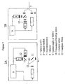
- Figure 1 is a generalized schematic of a biosensor according to an embodiment of the invention.
- Figure 2 illustrates two embodiments of the optical configuration in the optical portion of the sensor according to an embodiment of the present invention
- Figure 3 illustrates various arrangements of a biosensor tip
- Figure 3D illustrates an embodiment of a biosensor needle as used in the invention
- Figure 4 illustrates an embodiment of the invention that is a wearable in-vivo optical biosensor
- Figure 5 is a chart showing the performance of a fiber optic biosensor according to an embodiment of the invention tracking changing glucose levels in an anesthetized pig;
- Figure 6 is a chart showing the performance of a fiber optic biosensor according to an embodiment of the invention using a single 400 ⁇ m core fiber optic sensor and the optical configuration illustrated in Figure 2A ;
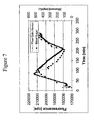
- Figure 7 shows the performance of a fiber optic biosensor according to an embodiment of the invention using a single 400 ⁇ m core fiber optic sensor and the optical configuration illustrated in Figure 2A ;
- Figure 8 illustrates an embodiment of the present invention including multiple electromagnetic energy detectors and an internal reference.
- the present invention involves a GGBP engineered to bind glucose within a desired clinical or analytical range.
- one or more luminescent reporter groups are associated with the GGBP. These luminescent reporter groups include organic aromatic dye molecules covalently coupled to cysteine residues in the protein or, for example, luminescent biomolecules such as proteins fused to the engineered binding protein. Cysteine or other amino acid groups may be engineered into the GGBP to provide sites of attachment for the luminescent reporter molecule. Binding of the glucose to the GGBP results in a change in the luminescent properties of one or more reporter groups. The luminescent property affected may be the absorption or emission wavelength, absorption or emission intensity, emission lifetime, emission polarization, and/or energy transfer efficiency. Binding of the glucose is also reversible, with the unbinding resulting again in a change in the luminescent properties of the reporter molecule.
- the at least one GGBP along with their associated reporter groups and the alginate matrix comprise the sensing element.
- the sensing element may also contain one or more reference groups.
- the reference group has a luminescence signal that is substantially unchanged upon binding of the glucose to the GGBP.
- the luminescence signal from the reference group provides an internal optical standard that can be used to correct for optical artifacts due to for example electronic drift in the optical system or to motion of the sample or optical silica fibers.
- the reference group can also be used for calibration.
- the reference group can be attached to any number of components of the device including the sensing element, a GGBP not containing the reporter group, the alginate matrix, the polymer chain, a biomolecule that is not a GGBP the optical silica fiber, or the needle.
- the reference group is attached to a GGBP that has been engineered to show no significant response to the glucose at physiologically relevant concentrations.
- the sensing element comprising at least one GGBP, one or more reporter groups, and optional reference groups, may be immobilized at the end of the optical silica fiber or inside a disposable needle that interfaces with the optical silica fiber.
- the optical system is capable of interrogating the luminescent response of the reporter and reference groups by passing light from an electromagnetic excitation source down the optical silica fiber to the distal end containing the sensing element.
- the optical system also monitors and interprets the return signals generated by the luminescence response of the reporter group and reference group.
- the luminescent properties of the reporter group either wavelength, intensity, lifetime, energy transfer efficiency, or polarization, change in response to glucose binding or unbinding from the GGBP.
- the optical system 2 includes a combination of elements including but not limited to electromagnetic energy emitters, electromagnetic energy detectors, various mirrors, filters, electronics, holographic optics, dichroic elements, and optical standards needed to send interrogating radiation from the electromagnetic energy emitter down the optical silica fiber to the sensing element and then to resolve and interpret the return luminescent signal.
- the return luminescent signal from the reporter group changes in response to changing concentrations of glucose to be detected.
- the optical system 2 may also comprise a computer or microprocessor 3 which handles signal processing, mathematical manipulation of one or more signals, and data storage and handling.
- the computer or microprocessor 3 may be in physical contact with the other components of the optical system or, in a preferred embodiment, may be physically separated by up to several meters from the other components of the optical system. In this embodiment, information from the electromagnetic energy detectors and electronic processing elements in the optical system is communicated wirelessly to the computer or microprocessor 3.
- the computer or microprocessor 3 may also store calibration information specific to the sensing element. Light of one or more wavelengths produced in the optical system 2 is channeled down an optical silica fiber 4 to the sensing element 6.
- the sensing element 6 can also consist of additional luminescent reference groups that are optionally attached to biomolecules, polymers, or organic molecules for the purpose of providing a reference or calibration signal. Sensing element 6 can be attached to the distal end of optical silica fiber 4 via an alginate matrix.
- FIG 2 is an enlargement of the optical system 2 in two typical embodiments.
- a dichroic mirror or beamsplitter 11 is used to direct light from an electromagnetic energy source 7 to the optical silica fiber 4.
- Excitation sources may consist of are lamps, laser diodes, or LEDs.
- the optical silica fiber 4 is a fiber optic cable, and the same fiber is used to transmit excitation light from electromagnetic energy source 7 to the sensing element 6 and also to transmit the luminescence signals from the reporter or reference groups back to the optical system 2.
- a dichroic element 11 preferably separates the return signal from the excitation light and directs the signal to electromagnetic energy detectors 8.
- Detectors may consist of, but are not limited to, for example, photodiodes, CCD chips, or photomultiplier tubes.
- additional dichroic elements may be used to direct portions of the return signals to multiple detectors.
- a luminescent reference group that is glucose insensitive is included along with the analyte-dependent reporter molecule to provide a reference signal. This reference signal can be used, for example, to correct for optical or electronic drift.
- Figure 2B illustrates a second embodiment in which a bifurcated optical bundle or fused optical silica fiber arrangement is used to transmit light to and from the sensing element.
- light from excitation source 7 is transmitted down one arm of the bifurcated silica fiber bundle.
- Return luminescent signals from the sensing element are detected using the second arm of the bifurcated silica fiber, so that in this case the silica fiber bundling serves to separate excitation from return luminescence.
- Dichroic optics, beamsplitters, or polarizers may additionally be used to further divide the return luminescence, based for example on wavelength or polarization.
- bandpass filters 12 can be used to select the luminescent wavelength to be detected.
- Power supply 9 supplies power to the optical system 2.
- Figure 3 illustrates representative methods of attaching the sensing element to the end of an optical silica fiber.
- the sensing element attached directly to the distal end of the optical silica fiber using convalent interactions.
- the sensing element is immobilized in an alginate matrix and the alginate matrix is attached to the distal end of the optical silica fiber using covalent interactions.
- the reactive groups of the alginate matrix are used to covalently bond the sensing element directly to the optical silica fiber by introducing amine groups on the surface of the silica fiber.
- a plastic or polymer sleeve fits over the distal end of the optical fiber and serves to house and protect the sensing element.
- Figure 3D shows the optical silica fiber held within the inside of the needle.
- the needle may have a modified bevel to control piercing depth and/or a side port to permit access of the glucose to the sensing element contained in the needle.
- the sensing element inside the needle is covalently attached directly to the optical silica fiber using the method described in the discussion of figure 3B .
- Figure 4 shows a preferred embodiment of a wearable optical biosensor.
- the needle, 21, is a steel needle approximately 1 - 10 mm in length, containing within it the sensing element, 6, immobilized onto an optical silica fiber, 22.
- the fiber, and needle assembly is centered in a plastic mount, 24.
- the needle, containing the optical silica fiber and the sensing element, is suitable to be inserted perpendicularly into the skin of a patient so that the chemistry at the end of the fiber resides in either the intradermal or subcutaneous space.
- Adhesive ring 25 then holds the plastic mount plus needle assembly in place.
- the optical system 2 then clamps over the plastic assembly, with the connector 26 interfacing the optical fiber 22 with the optical system.
- the optical system can be designed, for example, according to either optical embodiment 2a or 2b.
- Excitation sources may consist of arc lamps, laser diodes, or LEDs.
- Detectors may consist of photodiodes, CCD chips, or photomultiplier tubes.
- Glucose galactose binding protein was used with a triple mutation including a cysteine substituted for an glutamic acid at position 149, an arginine substituted for an alanine at position 213 and a serine substituted for leucine at position 238 (E149C/A213R/L238S).
- the protein was labeled at the 149 position with N,N'-dimethyl-N-(iodoacetyl)-N'-(7-nitrobenz-2-oxa-1,3-diazol-4-yl)ethylenediamine (IANBD amide)oxy.
- This mutated GGBP (E149C/A213R/L238S) is specific for glucose, and the reporter group undergoes a fluorescence intensity change in response to glucose binding.
- a multicoated or multilayer matrix was prepared as follows.
- a core matrix was formed by mixing 1 part dye-labeled binding protein (15 ⁇ M in PBS buffer, pH 7.4, prepared as described in PCT/US03/00203 ) with 2 to 4 parts 3 wt % alginate (v/v) in a scintillation vial and vortexing at slow speed.
- 3 mL of the resulting protein-alginate mixture was placed in a syringe and infused at a rate of 10 mL/h into 200 ml of 1 M CaCl 2 on a mixer, thereby forming beads of about 0.4 to 1.5 mm in diameter.
- the beads were mixed in CaCl 2 solution on the mixer for 15- 60 minutes.
- a containment layer was then formed by placing the beads from above in a solution of poly-L-lysine 0.01 %w/v in water, approximately 10 mL, for 1 hour, then drying the poly-lysine coated beads on an absorbent towel for 15 to 30 minutes. At this point the sensor was ready to be used.
- the fiber used was a bifurcated fiber optic. It contained six 400um fibers arranged around a central 400 ⁇ m fiber. The six fibers were used as the excitation conduit and the central fiber as the detection conduit. The total diameter of the fiber was 1.4 mm. Once the fiber was polished, Loctite 4011 medical grade glue was used to adhere the sensing element to the distal end of the fiber optic. The proximal end of the fiber was bifurcated, with one arm going to an excitation source and the other arm going to a detector. A 470 nm LED was used as the excitation source, and a commercial fluorescence spectrometer was used as the electromagnetic energy detector. The emission intensity at 540 nm was then measured.
- the distal end and sensing element of a biosensor formed in this manner was inserted through a 13 gauge needle into the side of an anesthetized pig, approximately 1-2 mm under the skin.
- Alternating solutions of lactated ringer's with and without 10% dextrose were infused through the ear vein of the pig to increase and decrease the pig's glucose levels in a controllable fashion.
- blood samples were pulled from the vena cava of the pig through a throat catheter, and blood sugar readings were tested on a handheld blood glucose meter. The fluorescence intensity of the biosensor was observed to track changing glucose levels in the anesthetized pig, as shown in Figure 5 .
- the binding protein was glucose galactose binding protein (GGBP), with a cysteine substituted for an glutamic acid at position 149, an arginine substituted for an alanine at position 213 and a serine substituted for leucine at position 238 (E149C/A213R/L238S).
- the protein was labeled at the 149 position with N,N'-dimethyl-N-(iodoacetyl)-N'-(7-nitrobenz-2-oxa-1,3-diazol-4-yl)ethylenediamine (IANBD amide).
- the biosensor was prepared by inserting the tip of a 400 ⁇ m core diameter fiber into a short piece of catheter tubing, and allowing the catheter tubing to overhang the fiber tip by 0.1 - 1 mm.
- the fiber comprised a silica core, silica cladding, and polyimide buffer.
- the fiber diameter was 400/440/470 ⁇ m, where the slashes denote diameters measured from the core/cladding/buffer exteriors.
- the immobilization matrix was a crosslinked alginate-based hydrogel, prepared by covalently crosslinking Pronova TM UP LVG alginate through the carboxyls with adipic acid dihydrazide (AAD) via carbodiimide chemistry.
- Pronova TM UP LVG was selected in this embodiment for its low viscosity and high guluronic to mannuronic ratio.
- a 2% alginate solution was prepared by dissolving 1 gram of alginate in 50 mL 0.1 M MES buffer (pH 6.5) and then adding 110 mg of AAD and 79 mg of hydroxybenzotriazole (HOBt). The solution was stored at 4 °C until used.
- the matrix was allowed to cross-link for 15 minutes, and then the fiber tip and matrix assembly were transferred to a 0.1M, 6.5 pH MES solution, where they were stored for 2 hours. At the end of the two hours, the sensing tips were placed in excess phosphate buffer solution (PBS, 0.0027 M potassium chloride, 0.137 sodium chloride, pH 7.4 where they were stored a minimum of 30 minutes to quench the reaction.
- PBS phosphate buffer solution
- the tips were incubated in a solution of labeled GGBP in PBS buffer [NBD-E149C/A213R/L238S GGBP] (53 uM, 50 uL) for approximately 8 hours.
- the sensors were protected from ambient light during incubation. After 8-24 hours of incubation, 50 uL of EDC/NHS (200 mM/50 mM) was then added to the incubation tube. After 40 minutes, the sensor tips were removed and placed in 50 uL of 1M, pH 8.5 ethanolamine to quench the reaction. After 20 minutes in the ethanolamine solution, the sensor tips were transferred to PBS solution, where they were allowed to sit for at least 24 hours while unreacted protein diffused out. The sensors were then transferred to fresh PBS and stored in the dark until ready to use.
- the fiber in this example was a single, 400 ⁇ m core multimode fiber (silica core, silica cladding, polyimide buffer). Since the same fiber transmits both the excitation and luminescence signal, dichroic optics were used to separate the luminescence from the excitation, as shown in Figure 2A .
- Excitation was with a 470 nm LED.
- a commercial dichroic filter was used to reflect the 470 nm excitation towards the input end of the fiber and transmit the fluorescence, centered at 550 nm, to the detector. Glass aspheric lenses were used both for beam collimation and to focus light into the fibers and onto the detectors. Scattered excitation was further removed from the detector using a 550 nm bandpass filter.
- SMA connectors pennitted rapid connection and disconnection of the fiber optic sensors.
- the electromagnetic energy detector was a single photon counting photomultiplier tube. Data acquisition was performed on a laptop computer communicating with the detector through an RS-232 connection
- FIG 6 In a trial, the distal end and sensing element of a biosensor formed in this manner was inserted into solutions of porcine serum containing different glucose concentrations. All porcine serum solutions were filtered through a 200 ⁇ m filter, and glucose levels in the solutions were measured on a clinical analyzer. Figure 6 illustrates the in vitro performance of the sensor. The initial glucose level in the serum was measured to be 56 mg/dL. Serum samples at 150 and 300 mg/dL were prepared by spiking concentrated 1M glucose in PBS into serum aliquots.
- a biosensor was formed by covalent attachment of a thin film to the surface of an optical fiber.
- the binding protein was glucose galactose binding protein (GGBP), with a cysteine substituted for a glutamic acid at position 149, an arginine substituted for an alanine at position 213 and a serine substituted for leucine at position 238 (E149C/A213R/L238S).
- the protein was labeled at the 149 position with N,N'-dimethyl-N-(iodoacetyl)-N'-(7-nitrobenz-2-oxa-1,3-diazol-4-yl)ethylenediamine (IANBD amide).
- the biosensor was prepared by covalent attachment of an alginate matrix to the amine-functionalized surface of a silica fiber.
- the fiber comprised a silica core, silica cladding, and polyimide buffer.
- the fiber diameter was 400/440/470 ⁇ m, where the slashes denote diameters measured from the core/cladding/buffer exteriors.
- the polyimide buffer was removed from the tip of the optical fiber by exposing the last few millimeters of the fiber to a torch for approximately 1 - 2 seconds. The residual polyimide was then wiped away. The tip with the buffer removed was then placed in 1 M sulfuric acid for 1 hour. Tips were then rinsed with distilled water, placed in ethanol for 15 minutes, and then submerged in anhydrous toluene for 15 minutes. The cleaned tips were then placed in warm (60° C) anhydrous toluene containing 1% 3-aminopropyltriethoxysilane (APTES) and allowed to react for 5 minutes. The tips were then removed from the APTES solution and washed with ethanol for 15 minutes. At the end of this process, the presence of amine groups on the surface of the fiber was verified by photoelectron spectroscopy.
- APTES 3-aminopropyltriethoxysilane
- the immobilization matrix was a crosslinked alginate-based hydrogel, prepared by covalently crosslinking Pronova TM UP LVG alginate, selected for its low viscosity and high guluronic to mannuronic ratio, through the carboxyls with adipic acid dihydrazide (AAD) via carbodiimide chemistry.
- a 2% alginate solution was prepared by dissolving 1 gram of alginate in 50 mL 0.1 M MES buffer (pH 6.5) and then adding 110 mg of AAD and 79 mg of hydroxybenzotriazole (HOBt).
- the tips were incubated in a solution of labeled GGBP in PBS buffer [NBD-E149C/A313R/L338S GGBP] (20 - 60 ⁇ M, 50 ⁇ L) for several hours.
- the sensors were protected from ambient light during incubation. After approximately 2 - 8 hour of incubation, 50 uL of EDC/NHS (200 mM/50 mM) were added to the incubation tube. After 5 - 40 minutes, the sensor tips were removed and placed in 50 ⁇ L of 1M, pH 8.5 ethanolamine to quench the reaction. After 20 minutes in the ethanolamine solution, the sensor tips were transferred to PBS solution, where they were allowed to sit for at least 8 hours while unreacted protein diffused out. The sensors were then transferred to fresh PBS and stored in the dark until ready to use.
- the optical reader was the same as described in the previous example, with the exception that the 470 nm excitation was modulated using a solenoid-driven shutter.
- the software permitted timed acquisition of fluorescence reading, graphical display of the results, and data analysis and calibration algorithms.
- the distal end and sensing element of a biosensor forked in this manner was then inserted into the side of an anesthetized pig. Insertion was done by inserting the fiber either intradermally or subcutaneously through a hole in the skin formed by a 18 - 24 gauge needle. Alternating solutions of lactated ringer's with and without 10% dextrose were infused through the ear vein of the pig to increase and decrease the pig's glucose levels in a controllable fashion. At intervals, blood samples were pulled from the vena cava of the pig through a throat catheter, and blood sugar readings were tested on a handheld blood glucose meter. The fluorescence intensity of the biosensor was observed to track changing blood glucose levels in the anesthetized pig, as shown in Figure 7 .
- the binding protein was glucose galactose binding protein (GGBP), with a cysteine substituted for a glutamic acid at position 149, an arginine substituted for an alanine at position 213 and a serine substituted for leucine at position 238 (E149C/A213R/L238S).
- the protein was labeled at the 149 position with the reporter group N,N'-dimethyl-N-(iodoacetyl)-N'-(7-nitrobenz-2-oxa-1,3-diazol-4-yl)ethylenediamine (IANBD amide).
- TR-E149C GGBP Texas Red® C 2 maleimide attached to GGBP with a cysteine substituted for a glutamic acid at position 149
- the biosensor was prepared by inserting the tip of a 400 ⁇ m core diameter fiber into a short piece of catheter tubing, allowing the catheter tubing to overhang the fiber tip by 0.1 - 0.5 mm.
- the fiber comprised a silica core, silica cladding, and polyimide buffer.
- the fiber diameter was 400/440/470 ⁇ m, where the slashes denote diameters measured from the core/cladding/buffer exteriors.
- the immobilization matrix was a crosslinked alginate-based hydrogel, prepared by covalently crosslinking Pronova TM UP LVG alginate, selected for its low viscosity and high guluronic to mannuronic ratio, through the carboxyls with adipic acid dihydrazide (AAD) via carbodiimide chemistry.
- a 2% alginate solution was prepared by dissolving 1 gram of alginate in 50 mL 0.1 M MES buffer (pH 6.5) and then adding 110 mg of AAD and 79 mg of hydroxybenzotriazole (HOBt). The solution was stored at 4 °C until used.
- a 0.5 mL aliquot of the alginate solution was then mixed with a 50 ⁇ L MES solution containing 10 mg of 1-ethyl-3- (3-dimethylamino-propyl) carbodiimide (EDC) and 90 ⁇ L of 60 ⁇ M TR-E149C GGBP.
- EDC 1-ethyl-3- (3-dimethylamino-propyl) carbodiimide
- TR-E149C GGBP 60 ⁇ M TR-E149C GGBP.
- the alginate, AAD, HOBt, EDC, TR-E149C mixture was aspirated into a 1 mL syringe, and a blunt 30 gauge needle was attached to the syringe. The needle was primed, and then the tip was inserted into the catheter tubing mold on the optical fiber.
- the catheter tubing on the fiber was filled, ensuring good contact between the tip of the fiber optic and the alginate matrix.
- the matrix was allowed to cross-link for 15 minutes, and then the fiber tip and matrix assembly were transferred to a 0.1M, 6.5 pH MES solution, where they were stored for 2 hours.
- PBS phosphate buffer solution
- the tips were incubated in a solution containing IANBD labeled GGBP in PBS buffer NBD-E149C/A213R/L238S GGBP. During the incubation period, the sensors were protected from ambient light. After approximately 2 - 8 hour of incubation, 50 ⁇ L of EDC/NHS (200 mM/50 mM) were added to the incubation tube. After 5 - 40 minutes, the sensor tips were removed and placed in 50 ⁇ L of 1M, pH 8.5 ethanolamine to quench the reaction. After 20 minutes in the ethanolamine solution, the sensor tips were transferred to PBS solution, where they were allowed to sit for at least 8 hours while unreacted protein diffused out. The sensors were then transferred to fresh PBS and stored in the dark until ready to use.
- EDC/NHS 200 mM/50 mM
- the fluorescence signal was read using an optical system following the configuration illustrated in Figure 2A .
- a 470 nm LED (LS-450) was used for excitation, and two single photon counting photomultiplier tubes were used as electromagnetic energy detectors.
- a commercial dichroic beamsplitter was used to reflect the 470 nm light from the electromagnetic energy emitter towards the fiber and to transmit the luminescence signals from the reporter and reference groups towards the detectors.
- a second dichroic beamsplitter was used to separate the luminescence signals from the reporter and reference groups, directing the emission from NBD-E149C/A213R/L238S towards one detector and the emission from TR-E149C GGBP towards the other detector.
- a 550 nm bandpass filter in front of one detector and a 610 nm bandpass filter in front of the other detector were used to achieve further spectral resolution for NBD-E149C/A213R/L238S and TR-E149C GGBP, respectively.
- FIG. 8 shows the sensor response to changing glucose levels.
- the 550 nm signal from the IANBD reporter group tracks changing glucose levels.
- the 610 run emission from the Texas Red® reporter group is substantially unchanged as glucose levels vary. However, a portion of the reporter group's emission also occurs at 610 nm.
- the detector in the optical system that tracks the 610 nm luminescence signal detects both the emission of the reference group and also the portion of the reporter group (IANBD) emission that occurs in this wavelength region.
- the contribution to the 610 nm signal from the reporter group is a constant fraction of the 550 nm signal, this contribution can be mathematically subtracted from the 610 nm signal to generate the signal due to the reference group alone.
- the 610 nm signal is substantially unchanging with glucose concentration as shown in Figure 8 .
Landscapes
- Health & Medical Sciences (AREA)
- Immunology (AREA)
- Life Sciences & Earth Sciences (AREA)
- Engineering & Computer Science (AREA)
- Chemical & Material Sciences (AREA)
- Molecular Biology (AREA)
- Hematology (AREA)
- Urology & Nephrology (AREA)
- Biomedical Technology (AREA)
- Physics & Mathematics (AREA)
- Analytical Chemistry (AREA)
- Biochemistry (AREA)
- General Health & Medical Sciences (AREA)
- General Physics & Mathematics (AREA)
- Pathology (AREA)
- Medicinal Chemistry (AREA)
- Cell Biology (AREA)
- Microbiology (AREA)
- Biotechnology (AREA)
- Food Science & Technology (AREA)
- Chemical Kinetics & Catalysis (AREA)
- Plasma & Fusion (AREA)
- Investigating, Analyzing Materials By Fluorescence Or Luminescence (AREA)
- Measurement Of The Respiration, Hearing Ability, Form, And Blood Characteristics Of Living Organisms (AREA)
- Investigating Or Analysing Materials By The Use Of Chemical Reactions (AREA)
- Eye Examination Apparatus (AREA)
Applications Claiming Priority (2)
| Application Number | Priority Date | Filing Date | Title |
|---|---|---|---|
| US10/721,797 US7496392B2 (en) | 2003-11-26 | 2003-11-26 | Fiber optic device for sensing analytes |
| PCT/US2004/038487 WO2005054831A1 (en) | 2003-11-26 | 2004-11-12 | Fiber optic device for sensing analytes |
Publications (2)
| Publication Number | Publication Date |
|---|---|
| EP1692493A1 EP1692493A1 (en) | 2006-08-23 |
| EP1692493B1 true EP1692493B1 (en) | 2010-04-28 |
Family
ID=34591881
Family Applications (1)
| Application Number | Title | Priority Date | Filing Date |
|---|---|---|---|
| EP04820029A Not-in-force EP1692493B1 (en) | 2003-11-26 | 2004-11-12 | Fiber optic device for sensing analytes |
Country Status (12)
| Country | Link |
|---|---|
| US (2) | US7496392B2 (zh) |
| EP (1) | EP1692493B1 (zh) |
| JP (1) | JP5442931B2 (zh) |
| CN (1) | CN1902476B (zh) |
| AT (1) | ATE466276T1 (zh) |
| AU (1) | AU2004295684B2 (zh) |
| BR (1) | BRPI0416985A (zh) |
| CA (1) | CA2546945C (zh) |
| DE (1) | DE602004026910D1 (zh) |
| NO (1) | NO20062941L (zh) |
| WO (1) | WO2005054831A1 (zh) |
| ZA (1) | ZA200605239B (zh) |
Cited By (1)
| Publication number | Priority date | Publication date | Assignee | Title |
|---|---|---|---|---|
| WO2014074621A1 (en) * | 2012-11-07 | 2014-05-15 | Glumetrics, Inc. | Dry insertion and one-point in vivo calibration of an optical analyte sensor |
Families Citing this family (118)
| Publication number | Priority date | Publication date | Assignee | Title |
|---|---|---|---|---|
| US8688188B2 (en) | 1998-04-30 | 2014-04-01 | Abbott Diabetes Care Inc. | Analyte monitoring device and methods of use |
| US8480580B2 (en) | 1998-04-30 | 2013-07-09 | Abbott Diabetes Care Inc. | Analyte monitoring device and methods of use |
| US8346337B2 (en) | 1998-04-30 | 2013-01-01 | Abbott Diabetes Care Inc. | Analyte monitoring device and methods of use |
| US8465425B2 (en) | 1998-04-30 | 2013-06-18 | Abbott Diabetes Care Inc. | Analyte monitoring device and methods of use |
| US9066695B2 (en) | 1998-04-30 | 2015-06-30 | Abbott Diabetes Care Inc. | Analyte monitoring device and methods of use |
| US6949816B2 (en) | 2003-04-21 | 2005-09-27 | Motorola, Inc. | Semiconductor component having first surface area for electrically coupling to a semiconductor chip and second surface area for electrically coupling to a substrate, and method of manufacturing same |
| US8974386B2 (en) | 1998-04-30 | 2015-03-10 | Abbott Diabetes Care Inc. | Analyte monitoring device and methods of use |
| US6175752B1 (en) | 1998-04-30 | 2001-01-16 | Therasense, Inc. | Analyte monitoring device and methods of use |
| US6560471B1 (en) | 2001-01-02 | 2003-05-06 | Therasense, Inc. | Analyte monitoring device and methods of use |
| US7041468B2 (en) | 2001-04-02 | 2006-05-09 | Therasense, Inc. | Blood glucose tracking apparatus and methods |
| US6916159B2 (en) | 2002-10-09 | 2005-07-12 | Therasense, Inc. | Device and method employing shape memory alloy |
| US7727181B2 (en) | 2002-10-09 | 2010-06-01 | Abbott Diabetes Care Inc. | Fluid delivery device with autocalibration |
| US7993108B2 (en) | 2002-10-09 | 2011-08-09 | Abbott Diabetes Care Inc. | Variable volume, shape memory actuated insulin dispensing pump |
| US7811231B2 (en) | 2002-12-31 | 2010-10-12 | Abbott Diabetes Care Inc. | Continuous glucose monitoring system and methods of use |
| US8771183B2 (en) | 2004-02-17 | 2014-07-08 | Abbott Diabetes Care Inc. | Method and system for providing data communication in continuous glucose monitoring and management system |
| US7679407B2 (en) | 2003-04-28 | 2010-03-16 | Abbott Diabetes Care Inc. | Method and apparatus for providing peak detection circuitry for data communication systems |
| US8066639B2 (en) | 2003-06-10 | 2011-11-29 | Abbott Diabetes Care Inc. | Glucose measuring device for use in personal area network |
| US7787923B2 (en) * | 2003-11-26 | 2010-08-31 | Becton, Dickinson And Company | Fiber optic device for sensing analytes and method of making same |
| EP1744795A1 (en) * | 2004-05-14 | 2007-01-24 | Becton, Dickinson and Company | Articles having bioactive surfaces and solvent-free methods of preparation thereof |
| WO2006078902A2 (en) * | 2005-01-19 | 2006-07-27 | Dermaspect, Llc | Devices and methods for identifying and monitoring changes of a suspect area on a patient |
| CA2601441A1 (en) | 2005-03-21 | 2006-09-28 | Abbott Diabetes Care Inc. | Method and system for providing integrated medication infusion and analyte monitoring system |
| US8112240B2 (en) | 2005-04-29 | 2012-02-07 | Abbott Diabetes Care Inc. | Method and apparatus for providing leak detection in data monitoring and management systems |
| US7768408B2 (en) | 2005-05-17 | 2010-08-03 | Abbott Diabetes Care Inc. | Method and system for providing data management in data monitoring system |
| US7620437B2 (en) | 2005-06-03 | 2009-11-17 | Abbott Diabetes Care Inc. | Method and apparatus for providing rechargeable power in data monitoring and management systems |
| US7740588B1 (en) * | 2005-06-24 | 2010-06-22 | Michael Sciarra | Wireless respiratory and heart rate monitoring system |
| US7756561B2 (en) | 2005-09-30 | 2010-07-13 | Abbott Diabetes Care Inc. | Method and apparatus for providing rechargeable power in data monitoring and management systems |
| US7583190B2 (en) | 2005-10-31 | 2009-09-01 | Abbott Diabetes Care Inc. | Method and apparatus for providing data communication in data monitoring and management systems |
| US7766829B2 (en) | 2005-11-04 | 2010-08-03 | Abbott Diabetes Care Inc. | Method and system for providing basal profile modification in analyte monitoring and management systems |
| US8344966B2 (en) | 2006-01-31 | 2013-01-01 | Abbott Diabetes Care Inc. | Method and system for providing a fault tolerant display unit in an electronic device |
| US7620438B2 (en) | 2006-03-31 | 2009-11-17 | Abbott Diabetes Care Inc. | Method and system for powering an electronic device |
| US8226891B2 (en) | 2006-03-31 | 2012-07-24 | Abbott Diabetes Care Inc. | Analyte monitoring devices and methods therefor |
| DK2029799T3 (da) * | 2006-04-20 | 2012-12-10 | Becton Dickinson Co | Termostabile proteiner og fremgangsmåder til fremstilling og anvendelse heraf |
| US7809441B2 (en) * | 2006-05-17 | 2010-10-05 | Cardiac Pacemakers, Inc. | Implantable medical device with chemical sensor and related methods |
| US20080071157A1 (en) | 2006-06-07 | 2008-03-20 | Abbott Diabetes Care, Inc. | Analyte monitoring system and method |
| US8579853B2 (en) | 2006-10-31 | 2013-11-12 | Abbott Diabetes Care Inc. | Infusion devices and methods |
| EP1944599A3 (en) | 2007-01-11 | 2008-11-12 | Fujifilm Corporation | Fluorescence analysis apparatus |
| AU2008213677A1 (en) * | 2007-02-06 | 2008-08-14 | Glumetrics, Inc. | Optical systems and methods for rationmetric measurement of blood glucose concentration |
| US8930203B2 (en) | 2007-02-18 | 2015-01-06 | Abbott Diabetes Care Inc. | Multi-function analyte test device and methods therefor |
| US8732188B2 (en) | 2007-02-18 | 2014-05-20 | Abbott Diabetes Care Inc. | Method and system for providing contextual based medication dosage determination |
| US8369916B2 (en) * | 2007-02-23 | 2013-02-05 | Becton, Dickinson And Company | Optical fiber connector |
| US8123686B2 (en) | 2007-03-01 | 2012-02-28 | Abbott Diabetes Care Inc. | Method and apparatus for providing rolling data in communication systems |
| US8456301B2 (en) | 2007-05-08 | 2013-06-04 | Abbott Diabetes Care Inc. | Analyte monitoring system and methods |
| US8665091B2 (en) | 2007-05-08 | 2014-03-04 | Abbott Diabetes Care Inc. | Method and device for determining elapsed sensor life |
| US7928850B2 (en) | 2007-05-08 | 2011-04-19 | Abbott Diabetes Care Inc. | Analyte monitoring system and methods |
| US8461985B2 (en) | 2007-05-08 | 2013-06-11 | Abbott Diabetes Care Inc. | Analyte monitoring system and methods |
| EP2162057A1 (en) * | 2007-05-10 | 2010-03-17 | Glumetrics, Inc. | Equilibrium non-consuming fluorescence sensor for real time intravascular glucose measurement |
| EP2150586B1 (en) * | 2007-05-22 | 2018-03-14 | Becton, Dickinson and Company | Dyes having ratiometric fluorescence response for detecting metabolites |
| JP5631215B2 (ja) | 2007-11-21 | 2014-11-26 | メドトロニック ミニメド インコーポレイテッド | 血糖管理維持システム |
| EP3501384A3 (en) | 2008-05-20 | 2019-10-16 | University Health Network | Method for fluorescence-based imaging and monitoring |
| CA2737461A1 (en) | 2008-09-19 | 2010-03-25 | Tandem Diabetes Care, Inc. | Solute concentration measurement device and related methods |
| ES2530450T3 (es) | 2008-10-02 | 2015-03-03 | Eyesense Ag | Elemento sensor implantable |
| ES2364375T3 (es) * | 2008-10-02 | 2011-09-01 | Eyesense Ag | Dispositivo de implantación para sensores de metabolitos. |
| US8437821B2 (en) * | 2009-01-06 | 2013-05-07 | Panasonic Corporation | Non-invasive body information measurement apparatus |
| US9375529B2 (en) * | 2009-09-02 | 2016-06-28 | Becton, Dickinson And Company | Extended use medical device |
| JP5804951B2 (ja) | 2009-01-12 | 2015-11-04 | ベクトン・ディキンソン・アンド・カンパニーBecton, Dickinson And Company | 柔軟な特徴部を備える内在の硬いカテーテル及び/又は柔軟なカテーテルアタッチメントの少なくとも1つを有する輸液セット及び/又はパッチポンプ |
| US8103456B2 (en) | 2009-01-29 | 2012-01-24 | Abbott Diabetes Care Inc. | Method and device for early signal attenuation detection using blood glucose measurements |
| US8560082B2 (en) | 2009-01-30 | 2013-10-15 | Abbott Diabetes Care Inc. | Computerized determination of insulin pump therapy parameters using real time and retrospective data processing |
| WO2010129375A1 (en) | 2009-04-28 | 2010-11-11 | Abbott Diabetes Care Inc. | Closed loop blood glucose control algorithm analysis |
| WO2010127050A1 (en) | 2009-04-28 | 2010-11-04 | Abbott Diabetes Care Inc. | Error detection in critical repeating data in a wireless sensor system |
| US20100294951A1 (en) * | 2009-05-22 | 2010-11-25 | Jeremy Parra | Sensitive gas-phase flourimeter at ambient pressure for nitrogen dioxide |
| US9184490B2 (en) | 2009-05-29 | 2015-11-10 | Abbott Diabetes Care Inc. | Medical device antenna systems having external antenna configurations |
| EP4276652A3 (en) | 2009-07-23 | 2024-01-31 | Abbott Diabetes Care, Inc. | Real time management of data relating to physiological control of glucose levels |
| US8939928B2 (en) | 2009-07-23 | 2015-01-27 | Becton, Dickinson And Company | Medical device having capacitive coupling communication and energy harvesting |
| EP2473098A4 (en) | 2009-08-31 | 2014-04-09 | Abbott Diabetes Care Inc | ANALYTICAL SIGNAL PROCESSING APPARATUS AND METHOD |
| US8993331B2 (en) | 2009-08-31 | 2015-03-31 | Abbott Diabetes Care Inc. | Analyte monitoring system and methods for managing power and noise |
| US10092691B2 (en) | 2009-09-02 | 2018-10-09 | Becton, Dickinson And Company | Flexible and conformal patch pump |
| EP2482720A4 (en) | 2009-09-29 | 2014-04-23 | Abbott Diabetes Care Inc | METHOD AND APPARATUS FOR PROVIDING NOTIFICATION FUNCTION IN SUBSTANCE MONITORING SYSTEMS |
| EP2483679A4 (en) * | 2009-09-30 | 2013-04-24 | Glumetrics Inc | SENSORS WITH THROMORETIC COATINGS |
| US8741591B2 (en) | 2009-10-09 | 2014-06-03 | The Research Foundation For The State University Of New York | pH-insensitive glucose indicator protein |
| US8467843B2 (en) | 2009-11-04 | 2013-06-18 | Glumetrics, Inc. | Optical sensor configuration for ratiometric correction of blood glucose measurement |
| WO2011101625A1 (en) * | 2010-02-19 | 2011-08-25 | Glysure Ltd | Subcutaneous glucose sensor |
| US8473222B2 (en) * | 2010-03-11 | 2013-06-25 | Glumetrics, Inc. | Measurement devices and methods for measuring analyte concentration incorporating temperature and pH correction |
| US10463287B2 (en) | 2010-10-06 | 2019-11-05 | Profusa, Inc. | Tissue-integrating sensors |
| US20120123230A1 (en) * | 2010-10-13 | 2012-05-17 | Tandem Diebetes Care, Inc. | Analyte monitoring systems and methods of use |
| US9950109B2 (en) | 2010-11-30 | 2018-04-24 | Becton, Dickinson And Company | Slide-activated angled inserter and cantilevered ballistic insertion for intradermal drug infusion |
| US8814831B2 (en) | 2010-11-30 | 2014-08-26 | Becton, Dickinson And Company | Ballistic microneedle infusion device |
| US8795230B2 (en) | 2010-11-30 | 2014-08-05 | Becton, Dickinson And Company | Adjustable height needle infusion device |
| CN102160777B (zh) * | 2011-03-10 | 2013-07-03 | 中国人民解放军第三军医大学第一附属医院 | 体液生物信息光纤动态检测系统 |
| US9980669B2 (en) | 2011-11-07 | 2018-05-29 | Abbott Diabetes Care Inc. | Analyte monitoring device and methods |
| DE102012201892A1 (de) * | 2012-02-09 | 2013-08-14 | Robert Bosch Gmbh | Bestimmung des Blutzuckerspiegels eines Patienten unter Verwendung eines implantierbaren Sensors und eines elektrischen Funktionspflasters |
| WO2013148957A1 (en) | 2012-03-28 | 2013-10-03 | Becton, Dickinson And Company | Hydrogel adhesion to molded polymers |
| US9968306B2 (en) | 2012-09-17 | 2018-05-15 | Abbott Diabetes Care Inc. | Methods and apparatuses for providing adverse condition notification with enhanced wireless communication range in analyte monitoring systems |
| US9160834B2 (en) | 2012-10-12 | 2015-10-13 | Becton, Dickinson And Company | Case with embedded electronics to provide interface between glucose sensor and smartphone |
| US10466247B2 (en) | 2012-11-20 | 2019-11-05 | Becton, Dickinson And Company | System and method for diagnosing sensor performance using analyte-independent ratiometric signals |
| WO2014100428A1 (en) | 2012-12-20 | 2014-06-26 | Becton, Dickinson And Company | System and method for using multiple sensor calibration methods |
| US9801578B2 (en) | 2013-01-22 | 2017-10-31 | Becton, Dickinson And Company | Reduced size optical coupler for fluorescence detection |
| GB201321245D0 (en) * | 2013-12-02 | 2014-01-15 | Univ Ireland Dublin | Gas sensor |
| EP2967453B1 (en) * | 2013-03-14 | 2020-05-13 | Becton, Dickinson and Company | Continuous glucose monitoring on-body sensor having a visual display |
| CN113274007A (zh) | 2013-03-14 | 2021-08-20 | 普罗菲尤萨股份有限公司 | 用于校正光学信号的方法和装置 |
| WO2014197786A2 (en) | 2013-06-06 | 2014-12-11 | Kintz Gregory J | Apparatus and methods for detecting optical signals from implanted sensors |
| US10379125B2 (en) | 2013-12-27 | 2019-08-13 | Becton, Dickinson And Company | System and method for dynamically calibrating and measuring analyte concentration in diabetes management monitors |
| EP3108222B1 (en) * | 2014-02-17 | 2022-03-30 | Eaton Intelligent Power Limited | Oxygen sensor comprising a tip coated optical fibre with a large diameter |
| CN103860145A (zh) * | 2014-03-27 | 2014-06-18 | 黄鹏 | 基于荧光检测方法的植入式检测装置 |
| WO2015146499A1 (ja) * | 2014-03-28 | 2015-10-01 | テルモ株式会社 | 蛍光センサ |
| US10004845B2 (en) | 2014-04-18 | 2018-06-26 | Becton, Dickinson And Company | Split piston metering pump |
| US11307194B2 (en) | 2014-05-19 | 2022-04-19 | University Of South Florida | Systems and methods for analyzing liquids |
| US9416775B2 (en) | 2014-07-02 | 2016-08-16 | Becton, Dickinson And Company | Internal cam metering pump |
| CN106714670A (zh) | 2014-07-24 | 2017-05-24 | 大学健康网络 | 用于诊断目的的数据的收集和分析 |
| US10252002B2 (en) | 2014-08-01 | 2019-04-09 | Becton, Dickinson And Company | Continuous glucose monitoring injection device |
| US10603661B2 (en) | 2014-08-26 | 2020-03-31 | Narwhal Analytical Corporation | Mini-fluidics cassette for colorimetric nutrient analysis and a method of using same |
| US10006882B2 (en) | 2014-11-21 | 2018-06-26 | EnLiSense, LLC | Biosensing system and methods using electron-ionic mechanisms at fluid-sensor interfaces |
| CN104523284B (zh) * | 2014-12-20 | 2016-05-18 | 佛山市南海区欧谱曼迪科技有限责任公司 | 一种基于全息纳米探测和微创组织液提取的血糖测量系统 |
| JP6511303B2 (ja) * | 2015-03-13 | 2019-05-15 | テルモ株式会社 | センサ |
| WO2016182348A1 (en) * | 2015-05-11 | 2016-11-17 | Samsung Electronics Co., Ltd. | Needle for biosensor and bio sensor including the same |
| US10716500B2 (en) | 2015-06-29 | 2020-07-21 | Cardiac Pacemakers, Inc. | Systems and methods for normalization of chemical sensor data based on fluid state changes |
| AU2016361420B2 (en) | 2015-11-23 | 2021-05-06 | Perkinelmer Health Sciences, Inc. | Hollow polymer fiber optic system for single analyte and multiplexed analyte detection |
| US10850046B2 (en) * | 2016-03-28 | 2020-12-01 | Becton, Dickinson And Company | Cannula locator device |
| US10835718B2 (en) | 2016-03-28 | 2020-11-17 | Becton, Dickinson And Company | Cannula with light-emitting optical fiber |
| US11478150B2 (en) | 2016-03-28 | 2022-10-25 | Becton, Dickinson And Company | Optical fiber sensor |
| CN109997198B (zh) | 2016-10-12 | 2023-08-04 | 英佰达公司 | 综合疾病管理系统 |
| WO2018119400A1 (en) | 2016-12-22 | 2018-06-28 | Profusa, Inc. | System and single-channel luminescent sensor for and method of determining analyte value |
| CN108968976B (zh) | 2017-05-31 | 2022-09-13 | 心脏起搏器股份公司 | 具有化学传感器的植入式医疗设备 |
| CN109381195B (zh) | 2017-08-10 | 2023-01-10 | 心脏起搏器股份公司 | 包括电解质传感器融合的系统和方法 |
| CN109419515B (zh) | 2017-08-23 | 2023-03-24 | 心脏起搏器股份公司 | 具有分级激活的可植入化学传感器 |
| CN109864746B (zh) | 2017-12-01 | 2023-09-29 | 心脏起搏器股份公司 | 用于医学装置的多模式分析物传感器 |
| CN109864747B (zh) | 2017-12-05 | 2023-08-25 | 心脏起搏器股份公司 | 多模式分析物传感器光电子接口 |
| JP2022507886A (ja) * | 2018-11-21 | 2022-01-18 | エイシーズ メディカル エルエルシー | バイオマーカー検出システム |
| CN110296970A (zh) * | 2019-08-02 | 2019-10-01 | 普乐药业有限公司 | 便携式血糖测量仪 |
Citations (4)
| Publication number | Priority date | Publication date | Assignee | Title |
|---|---|---|---|---|
| EP0481740A2 (en) * | 1990-10-16 | 1992-04-22 | Puritan-Bennett Corporation | Optical fiber PH microsensor and method of manufacture |
| US5700897A (en) * | 1985-04-08 | 1997-12-23 | Optical Sensors Incorporated | Method for making fluorescent polymers |
| WO2003057851A2 (en) * | 2002-01-04 | 2003-07-17 | Becton, Dickinson And Company | Binding proteins as biosensors |
| WO2003057734A1 (en) * | 2002-01-04 | 2003-07-17 | Becton, Dickinson And Company | Entrapped binding proteins as biosensors |
Family Cites Families (70)
| Publication number | Priority date | Publication date | Assignee | Title |
|---|---|---|---|---|
| US4548907A (en) * | 1983-09-14 | 1985-10-22 | Allied Corporation | Fluorescent fluid determination method and apparatus |
| US5001054A (en) * | 1986-06-26 | 1991-03-19 | Becton, Dickinson And Company | Method for monitoring glucose |
| US4981779A (en) * | 1986-06-26 | 1991-01-01 | Becton, Dickinson And Company | Apparatus for monitoring glucose |
| EP0309214A3 (en) * | 1987-09-22 | 1990-03-14 | BAXTER INTERNATIONAL INC. (a Delaware corporation) | Fiber optical probe connector for physiologic measurement devices |
| US4907857A (en) * | 1988-07-25 | 1990-03-13 | Abbott Laboratories | Optical fiber distribution system for an optical fiber sensor |
| US4925268A (en) * | 1988-07-25 | 1990-05-15 | Abbott Laboratories | Fiber-optic physiological probes |
| JPH0257950A (ja) * | 1988-08-24 | 1990-02-27 | Terumo Corp | イオン濃度測定用プローブ |
| IL89159A0 (en) * | 1989-02-02 | 1989-09-10 | Optical Chemical Tech Oct | Medical probe |
| US6010867A (en) * | 1989-04-19 | 2000-01-04 | Ibiden Co., Ltd. | Reagent for biomaterials assay, preparation method thereof, and assay method |
| DE3919696A1 (de) * | 1989-06-16 | 1991-01-10 | Bayer Ag | Reaktivklebstoffe auf polyurethanbasis |
| FR2650076B1 (fr) * | 1989-07-20 | 1991-10-04 | Commissariat Energie Atomique | Capteur chimique actif a fibre optique et son procede de fabrication |
| US5176881A (en) * | 1989-08-11 | 1993-01-05 | The University Of Tennessee Research Corporation | Fiber optic-based regenerable biosensor |
| EP0413499A3 (en) * | 1989-08-16 | 1991-07-24 | Puritan-Bennett Corporation | Sensor element and method for making the same |
| US5342789A (en) * | 1989-12-14 | 1994-08-30 | Sensor Technologies, Inc. | Method and device for detecting and quantifying glucose in body fluids |
| US6040194A (en) * | 1989-12-14 | 2000-03-21 | Sensor Technologies, Inc. | Methods and device for detecting and quantifying substances in body fluids |
| US5127405A (en) * | 1990-02-16 | 1992-07-07 | The Boc Group, Inc. | Biomedical fiber optic probe with frequency domain signal processing |
| US5143066A (en) * | 1990-05-08 | 1992-09-01 | University Of Pittsburgh | Optical fiber sensors for continuous monitoring of biochemicals and related method |
| US5154890A (en) * | 1990-11-07 | 1992-10-13 | Hewlett-Packard Company | Fiber optic potassium ion sensor |
| US5244813A (en) * | 1991-01-25 | 1993-09-14 | Trustees Of Tufts College | Fiber optic sensor, apparatus, and methods for detecting an organic analyte in a fluid or vapor sample |
| US5377676A (en) * | 1991-04-03 | 1995-01-03 | Cedars-Sinai Medical Center | Method for determining the biodistribution of substances using fluorescence spectroscopy |
| CA2069537A1 (en) * | 1991-06-07 | 1992-12-08 | Thomas A. Cook | Multiple output referencing system for evanescent wave sensor |
| US5340715A (en) * | 1991-06-07 | 1994-08-23 | Ciba Corning Diagnostics Corp. | Multiple surface evanescent wave sensor with a reference |
| JP3107649B2 (ja) * | 1991-12-20 | 2000-11-13 | イビデン株式会社 | 蛍光免疫測定装置 |
| US6256522B1 (en) * | 1992-11-23 | 2001-07-03 | University Of Pittsburgh Of The Commonwealth System Of Higher Education | Sensors for continuous monitoring of biochemicals and related method |
| JP3305398B2 (ja) * | 1993-03-31 | 2002-07-22 | 三菱レイヨン株式会社 | 光ファイバセンサ |
| US5341805A (en) * | 1993-04-06 | 1994-08-30 | Cedars-Sinai Medical Center | Glucose fluorescence monitor and method |
| US5512492A (en) * | 1993-05-18 | 1996-04-30 | University Of Utah Research Foundation | Waveguide immunosensor with coating chemistry providing enhanced sensitivity |
| US5552272A (en) * | 1993-06-10 | 1996-09-03 | Biostar, Inc. | Detection of an analyte by fluorescence using a thin film optical device |
| US5569911A (en) * | 1993-07-19 | 1996-10-29 | General Electric Company | Fiber optic system for remote fluorescent sensing using excitation and return fibers |
| JPH07110330A (ja) * | 1993-09-01 | 1995-04-25 | Bio Sensor Kenkyusho:Kk | 光学センサー |
| US5496997A (en) * | 1994-01-03 | 1996-03-05 | Pope; Edward J. A. | Sensor incorporating an optical fiber and a solid porous inorganic microsphere |
| US5515864A (en) * | 1994-04-21 | 1996-05-14 | Zuckerman; Ralph | Method and apparatus for the in vivo measurement of oxygen concentration levels by the indirect determination of fluoescence lifetime |
| US5605152A (en) * | 1994-07-18 | 1997-02-25 | Minimed Inc. | Optical glucose sensor |
| AT403961B (de) * | 1995-03-17 | 1998-07-27 | Avl Verbrennungskraft Messtech | Optochemisches messsystem mit einem fluoreszenzsensor |
| US5628310A (en) * | 1995-05-19 | 1997-05-13 | Joseph R. Lakowicz | Method and apparatus to perform trans-cutaneous analyte monitoring |
| US5656241A (en) * | 1995-09-07 | 1997-08-12 | Optical Sensors Incorporated | Method for manufacturing fiber optic sensors |
| US6766183B2 (en) * | 1995-11-22 | 2004-07-20 | Medtronic Minimed, Inc. | Long wave fluorophore sensor compounds and other fluorescent sensor compounds in polymers |
| US5747349A (en) * | 1996-03-20 | 1998-05-05 | University Of Washington | Fluorescent reporter beads for fluid analysis |
| US5938595A (en) * | 1996-05-24 | 1999-08-17 | The Regents Of The University Of California | Fiber optic D dimer biosensor |
| JPH10132747A (ja) * | 1996-10-01 | 1998-05-22 | Texas Instr Inc <Ti> | 小型集積センサ台 |
| US6111248A (en) * | 1996-10-01 | 2000-08-29 | Texas Instruments Incorporated | Self-contained optical sensor system |
| JPH10132749A (ja) * | 1996-10-01 | 1998-05-22 | Texas Instr Inc <Ti> | 集積蛍光生化学センサ |
| US5946083A (en) * | 1997-10-01 | 1999-08-31 | Texas Instruments Incorporated | Fixed optic sensor system and distributed sensor network |
| ATE278352T1 (de) * | 1997-08-09 | 2004-10-15 | Roche Diagnostics Gmbh | Analysevorrichtung zur in-vivo-analyse im körper eines patienten |
| US5900512A (en) | 1997-09-11 | 1999-05-04 | Albemarle Corporation | Oxidation process |
| US6081736A (en) * | 1997-10-20 | 2000-06-27 | Alfred E. Mann Foundation | Implantable enzyme-based monitoring systems adapted for long term use |
| AU760743B2 (en) * | 1997-12-31 | 2003-05-22 | Duke University | Biosensor |
| US6289229B1 (en) * | 1998-01-20 | 2001-09-11 | Scimed Life Systems, Inc. | Readable probe array for in vivo use |
| US6020207A (en) * | 1998-06-17 | 2000-02-01 | World Precision Instruments, Inc. | Optical analysis technique and sensors for use therein |
| US6157442A (en) * | 1998-06-19 | 2000-12-05 | Microsense International Llc | Micro optical fiber sensor device |
| US6197534B1 (en) * | 1998-07-17 | 2001-03-06 | Joseph R. Lakowicz | Engineered proteins for analyte sensing |
| US6535753B1 (en) * | 1998-08-20 | 2003-03-18 | Microsense International, Llc | Micro-invasive method for painless detection of analytes in extra-cellular space |
| US6197257B1 (en) * | 1998-08-20 | 2001-03-06 | Microsense Of St. Louis, Llc | Micro sensor device |
| CN100385232C (zh) * | 1998-08-26 | 2008-04-30 | 医药及科学传感器公司 | 基于光学的感测装置 |
| US6304766B1 (en) * | 1998-08-26 | 2001-10-16 | Sensors For Medicine And Science | Optical-based sensing devices, especially for in-situ sensing in humans |
| US6936044B2 (en) * | 1998-11-30 | 2005-08-30 | Light Bioscience, Llc | Method and apparatus for the stimulation of hair growth |
| US6432723B1 (en) * | 1999-01-22 | 2002-08-13 | Clinical Micro Sensors, Inc. | Biosensors utilizing ligand induced conformation changes |
| US6704587B1 (en) * | 1999-04-01 | 2004-03-09 | Spectrx, Inc. | Dual function assay device |
| US6584214B1 (en) * | 1999-04-23 | 2003-06-24 | Massachusetts Institute Of Technology | Identification and verification using complex, three-dimensional structural features |
| WO2000074763A2 (en) | 1999-06-04 | 2000-12-14 | Georgia Tech Research Corporation | Devices and methods for enhanced microneedle penetration of biological barriers |
| US6366793B1 (en) * | 1999-09-10 | 2002-04-02 | Beckman Coulter, Inc. | Minimally invasive methods for measuring analtes in vivo |
| CA2333346C (en) * | 2000-01-31 | 2013-01-22 | The Penn State Research Foundation | Interrogation of changes in the contents of a sealed container |
| WO2001075450A2 (en) * | 2000-04-04 | 2001-10-11 | The Regents Of The University Of California | Fluorescent lifetime assays for non-invasive quantification of analytes |
| US6540675B2 (en) | 2000-06-27 | 2003-04-01 | Rosedale Medical, Inc. | Analyte monitor |
| GB0025147D0 (en) | 2000-10-13 | 2000-11-29 | Torsana Diabetes Diagnostics A | Optical sensor for in situ measurement of analytes |
| AU2002367906A1 (en) * | 2001-10-02 | 2003-12-12 | Alfred E. Mann Institute For Biomedical Engineering At The University Of Southern California | Internal biochemical sensing device |
| US20030232383A1 (en) | 2001-11-02 | 2003-12-18 | Sylvia Daunert | Novel reagentless sensing system for measuring carbohydrates based on the galactose/glucose binding protein |
| US7064103B2 (en) * | 2002-01-04 | 2006-06-20 | Becton, Dickinson And Company | Binding protein as biosensors |
| WO2004044557A2 (en) | 2002-11-12 | 2004-05-27 | Argose, Inc. | Non-invasive measurement of analytes |
| US20040234962A1 (en) * | 2003-05-02 | 2004-11-25 | Javier Alarcon | Multicoated or multilayer entrapment matrix for protein biosensor |
-
2003
- 2003-11-26 US US10/721,797 patent/US7496392B2/en not_active Expired - Fee Related
-
2004
- 2004-11-12 AU AU2004295684A patent/AU2004295684B2/en not_active Ceased
- 2004-11-12 WO PCT/US2004/038487 patent/WO2005054831A1/en active Application Filing
- 2004-11-12 EP EP04820029A patent/EP1692493B1/en not_active Not-in-force
- 2004-11-12 DE DE602004026910T patent/DE602004026910D1/de active Active
- 2004-11-12 CA CA2546945A patent/CA2546945C/en not_active Expired - Fee Related
- 2004-11-12 CN CN2004800402659A patent/CN1902476B/zh not_active Expired - Fee Related
- 2004-11-12 JP JP2006541334A patent/JP5442931B2/ja not_active Expired - Fee Related
- 2004-11-12 AT AT04820029T patent/ATE466276T1/de not_active IP Right Cessation
- 2004-11-12 BR BRPI0416985-9A patent/BRPI0416985A/pt not_active Application Discontinuation
-
2006
- 2006-06-23 NO NO20062941A patent/NO20062941L/no not_active Application Discontinuation
- 2006-06-26 ZA ZA2006/05239A patent/ZA200605239B/en unknown
-
2007
- 2007-08-16 US US11/840,069 patent/US7792561B2/en not_active Expired - Fee Related
Patent Citations (4)
| Publication number | Priority date | Publication date | Assignee | Title |
|---|---|---|---|---|
| US5700897A (en) * | 1985-04-08 | 1997-12-23 | Optical Sensors Incorporated | Method for making fluorescent polymers |
| EP0481740A2 (en) * | 1990-10-16 | 1992-04-22 | Puritan-Bennett Corporation | Optical fiber PH microsensor and method of manufacture |
| WO2003057851A2 (en) * | 2002-01-04 | 2003-07-17 | Becton, Dickinson And Company | Binding proteins as biosensors |
| WO2003057734A1 (en) * | 2002-01-04 | 2003-07-17 | Becton, Dickinson And Company | Entrapped binding proteins as biosensors |
Cited By (2)
| Publication number | Priority date | Publication date | Assignee | Title |
|---|---|---|---|---|
| WO2014074621A1 (en) * | 2012-11-07 | 2014-05-15 | Glumetrics, Inc. | Dry insertion and one-point in vivo calibration of an optical analyte sensor |
| US9757057B2 (en) | 2012-11-07 | 2017-09-12 | Medtronic Minimed, Inc. | Dry insertion and one-point in vivo calibration of an optical analyte sensor |
Also Published As
| Publication number | Publication date |
|---|---|
| NO20062941L (no) | 2006-08-24 |
| US7792561B2 (en) | 2010-09-07 |
| ZA200605239B (en) | 2008-01-08 |
| JP2007513333A (ja) | 2007-05-24 |
| JP5442931B2 (ja) | 2014-03-19 |
| DE602004026910D1 (de) | 2010-06-10 |
| AU2004295684A1 (en) | 2005-06-16 |
| CA2546945C (en) | 2013-01-15 |
| BRPI0416985A (pt) | 2007-02-21 |
| US20050113657A1 (en) | 2005-05-26 |
| US7496392B2 (en) | 2009-02-24 |
| EP1692493A1 (en) | 2006-08-23 |
| WO2005054831A1 (en) | 2005-06-16 |
| CN1902476B (zh) | 2013-12-04 |
| CN1902476A (zh) | 2007-01-24 |
| US20080198358A1 (en) | 2008-08-21 |
| CA2546945A1 (en) | 2005-06-16 |
| AU2004295684B2 (en) | 2010-01-21 |
| ATE466276T1 (de) | 2010-05-15 |
Similar Documents
| Publication | Publication Date | Title |
|---|---|---|
| EP1692493B1 (en) | Fiber optic device for sensing analytes | |
| US7787923B2 (en) | Fiber optic device for sensing analytes and method of making same | |
| US20050148003A1 (en) | Methods of correcting a luminescence value, and methods of determining a corrected analyte concentration | |
| EP1098658B1 (en) | Engineered proteins for analyte sensing | |
| Badugu et al. | A glucose-sensing contact lens: from bench top to patient | |
| Badugu et al. | Ophthalmic glucose monitoring using disposable contact lenses—a review | |
| Ballerstadt et al. | Fluorescence resonance energy transfer-based near-infrared fluorescence sensor for glucose monitoring | |
| US20050118726A1 (en) | System and method for detecting bioanalytes and method for producing a bioanalyte sensor | |
| US20050267326A1 (en) | Percutaneous chemical sensor based on fluorescence resonant energy transfer (FRET) | |
| Siegrist et al. | Continuous glucose sensor using novel genetically engineered binding polypeptides towards in vivo applications | |
| WO2009021039A1 (en) | Device for detection of molecules of interest | |
| MXPA06005806A (en) | Fiber optic device for sensing analytes | |
| Lakowicz | A glucose-sensing contact lens: from bench top to patient Ramachandram Badugu1, Joseph R Lakowicz1 and Chris D Geddes1, 2 |
Legal Events
| Date | Code | Title | Description |
|---|---|---|---|
| PUAI | Public reference made under article 153(3) epc to a published international application that has entered the european phase |
Free format text: ORIGINAL CODE: 0009012 |
|
| 17P | Request for examination filed |
Effective date: 20060619 |
|
| AK | Designated contracting states |
Kind code of ref document: A1 Designated state(s): AT BE BG CH CY CZ DE DK EE ES FI FR GB GR HU IE IS IT LI LU MC NL PL PT RO SE SI SK TR |
|
| 17Q | First examination report despatched |
Effective date: 20061128 |
|
| DAX | Request for extension of the european patent (deleted) | ||
| GRAP | Despatch of communication of intention to grant a patent |
Free format text: ORIGINAL CODE: EPIDOSNIGR1 |
|
| GRAS | Grant fee paid |
Free format text: ORIGINAL CODE: EPIDOSNIGR3 |
|
| GRAA | (expected) grant |
Free format text: ORIGINAL CODE: 0009210 |
|
| AK | Designated contracting states |
Kind code of ref document: B1 Designated state(s): AT BE BG CH CY CZ DE DK EE ES FI FR GB GR HU IE IS IT LI LU MC NL PL PT RO SE SI SK TR |
|
| REG | Reference to a national code |
Ref country code: GB Ref legal event code: FG4D |
|
| REG | Reference to a national code |
Ref country code: CH Ref legal event code: EP |
|
| REG | Reference to a national code |
Ref country code: IE Ref legal event code: FG4D |
|
| REF | Corresponds to: |
Ref document number: 602004026910 Country of ref document: DE Date of ref document: 20100610 Kind code of ref document: P |
|
| REG | Reference to a national code |
Ref country code: NL Ref legal event code: VDEP Effective date: 20100428 |
|
| PG25 | Lapsed in a contracting state [announced via postgrant information from national office to epo] |
Ref country code: NL Free format text: LAPSE BECAUSE OF FAILURE TO SUBMIT A TRANSLATION OF THE DESCRIPTION OR TO PAY THE FEE WITHIN THE PRESCRIBED TIME-LIMIT Effective date: 20100428 Ref country code: SE Free format text: LAPSE BECAUSE OF FAILURE TO SUBMIT A TRANSLATION OF THE DESCRIPTION OR TO PAY THE FEE WITHIN THE PRESCRIBED TIME-LIMIT Effective date: 20100428 Ref country code: ES Free format text: LAPSE BECAUSE OF FAILURE TO SUBMIT A TRANSLATION OF THE DESCRIPTION OR TO PAY THE FEE WITHIN THE PRESCRIBED TIME-LIMIT Effective date: 20100808 |
|
| PG25 | Lapsed in a contracting state [announced via postgrant information from national office to epo] |
Ref country code: SI Free format text: LAPSE BECAUSE OF FAILURE TO SUBMIT A TRANSLATION OF THE DESCRIPTION OR TO PAY THE FEE WITHIN THE PRESCRIBED TIME-LIMIT Effective date: 20100428 Ref country code: AT Free format text: LAPSE BECAUSE OF FAILURE TO SUBMIT A TRANSLATION OF THE DESCRIPTION OR TO PAY THE FEE WITHIN THE PRESCRIBED TIME-LIMIT Effective date: 20100428 Ref country code: IS Free format text: LAPSE BECAUSE OF FAILURE TO SUBMIT A TRANSLATION OF THE DESCRIPTION OR TO PAY THE FEE WITHIN THE PRESCRIBED TIME-LIMIT Effective date: 20100828 Ref country code: FI Free format text: LAPSE BECAUSE OF FAILURE TO SUBMIT A TRANSLATION OF THE DESCRIPTION OR TO PAY THE FEE WITHIN THE PRESCRIBED TIME-LIMIT Effective date: 20100428 |
|
| PG25 | Lapsed in a contracting state [announced via postgrant information from national office to epo] |
Ref country code: CY Free format text: LAPSE BECAUSE OF FAILURE TO SUBMIT A TRANSLATION OF THE DESCRIPTION OR TO PAY THE FEE WITHIN THE PRESCRIBED TIME-LIMIT Effective date: 20100428 Ref country code: GR Free format text: LAPSE BECAUSE OF FAILURE TO SUBMIT A TRANSLATION OF THE DESCRIPTION OR TO PAY THE FEE WITHIN THE PRESCRIBED TIME-LIMIT Effective date: 20100729 Ref country code: PL Free format text: LAPSE BECAUSE OF FAILURE TO SUBMIT A TRANSLATION OF THE DESCRIPTION OR TO PAY THE FEE WITHIN THE PRESCRIBED TIME-LIMIT Effective date: 20100428 |
|
| PG25 | Lapsed in a contracting state [announced via postgrant information from national office to epo] |
Ref country code: PT Free format text: LAPSE BECAUSE OF FAILURE TO SUBMIT A TRANSLATION OF THE DESCRIPTION OR TO PAY THE FEE WITHIN THE PRESCRIBED TIME-LIMIT Effective date: 20100830 Ref country code: DK Free format text: LAPSE BECAUSE OF FAILURE TO SUBMIT A TRANSLATION OF THE DESCRIPTION OR TO PAY THE FEE WITHIN THE PRESCRIBED TIME-LIMIT Effective date: 20100428 Ref country code: EE Free format text: LAPSE BECAUSE OF FAILURE TO SUBMIT A TRANSLATION OF THE DESCRIPTION OR TO PAY THE FEE WITHIN THE PRESCRIBED TIME-LIMIT Effective date: 20100428 |
|
| PG25 | Lapsed in a contracting state [announced via postgrant information from national office to epo] |
Ref country code: BE Free format text: LAPSE BECAUSE OF FAILURE TO SUBMIT A TRANSLATION OF THE DESCRIPTION OR TO PAY THE FEE WITHIN THE PRESCRIBED TIME-LIMIT Effective date: 20100428 Ref country code: CZ Free format text: LAPSE BECAUSE OF FAILURE TO SUBMIT A TRANSLATION OF THE DESCRIPTION OR TO PAY THE FEE WITHIN THE PRESCRIBED TIME-LIMIT Effective date: 20100428 Ref country code: RO Free format text: LAPSE BECAUSE OF FAILURE TO SUBMIT A TRANSLATION OF THE DESCRIPTION OR TO PAY THE FEE WITHIN THE PRESCRIBED TIME-LIMIT Effective date: 20100428 Ref country code: SK Free format text: LAPSE BECAUSE OF FAILURE TO SUBMIT A TRANSLATION OF THE DESCRIPTION OR TO PAY THE FEE WITHIN THE PRESCRIBED TIME-LIMIT Effective date: 20100428 |
|
| PLBE | No opposition filed within time limit |
Free format text: ORIGINAL CODE: 0009261 |
|
| STAA | Information on the status of an ep patent application or granted ep patent |
Free format text: STATUS: NO OPPOSITION FILED WITHIN TIME LIMIT |
|
| PG25 | Lapsed in a contracting state [announced via postgrant information from national office to epo] |
Ref country code: IT Free format text: LAPSE BECAUSE OF FAILURE TO SUBMIT A TRANSLATION OF THE DESCRIPTION OR TO PAY THE FEE WITHIN THE PRESCRIBED TIME-LIMIT Effective date: 20100428 |
|
| 26N | No opposition filed |
Effective date: 20110131 |
|
| PG25 | Lapsed in a contracting state [announced via postgrant information from national office to epo] |
Ref country code: MC Free format text: LAPSE BECAUSE OF NON-PAYMENT OF DUE FEES Effective date: 20101130 |
|
| REG | Reference to a national code |
Ref country code: CH Ref legal event code: PL |
|
| PG25 | Lapsed in a contracting state [announced via postgrant information from national office to epo] |
Ref country code: CH Free format text: LAPSE BECAUSE OF NON-PAYMENT OF DUE FEES Effective date: 20101130 Ref country code: LI Free format text: LAPSE BECAUSE OF NON-PAYMENT OF DUE FEES Effective date: 20101130 |
|
| PG25 | Lapsed in a contracting state [announced via postgrant information from national office to epo] |
Ref country code: IE Free format text: LAPSE BECAUSE OF NON-PAYMENT OF DUE FEES Effective date: 20101112 |
|
| PG25 | Lapsed in a contracting state [announced via postgrant information from national office to epo] |
Ref country code: LU Free format text: LAPSE BECAUSE OF NON-PAYMENT OF DUE FEES Effective date: 20101112 Ref country code: HU Free format text: LAPSE BECAUSE OF FAILURE TO SUBMIT A TRANSLATION OF THE DESCRIPTION OR TO PAY THE FEE WITHIN THE PRESCRIBED TIME-LIMIT Effective date: 20101029 Ref country code: BG Free format text: LAPSE BECAUSE OF FAILURE TO SUBMIT A TRANSLATION OF THE DESCRIPTION OR TO PAY THE FEE WITHIN THE PRESCRIBED TIME-LIMIT Effective date: 20100428 |
|
| PG25 | Lapsed in a contracting state [announced via postgrant information from national office to epo] |
Ref country code: TR Free format text: LAPSE BECAUSE OF FAILURE TO SUBMIT A TRANSLATION OF THE DESCRIPTION OR TO PAY THE FEE WITHIN THE PRESCRIBED TIME-LIMIT Effective date: 20100428 |
|
| PG25 | Lapsed in a contracting state [announced via postgrant information from national office to epo] |
Ref country code: BG Free format text: LAPSE BECAUSE OF FAILURE TO SUBMIT A TRANSLATION OF THE DESCRIPTION OR TO PAY THE FEE WITHIN THE PRESCRIBED TIME-LIMIT Effective date: 20100728 |
|
| PGFP | Annual fee paid to national office [announced via postgrant information from national office to epo] |
Ref country code: DE Payment date: 20141128 Year of fee payment: 11 Ref country code: FR Payment date: 20141118 Year of fee payment: 11 Ref country code: GB Payment date: 20141127 Year of fee payment: 11 |
|
| REG | Reference to a national code |
Ref country code: DE Ref legal event code: R119 Ref document number: 602004026910 Country of ref document: DE |
|
| GBPC | Gb: european patent ceased through non-payment of renewal fee |
Effective date: 20151112 |
|
| REG | Reference to a national code |
Ref country code: FR Ref legal event code: ST Effective date: 20160729 |
|
| PG25 | Lapsed in a contracting state [announced via postgrant information from national office to epo] |
Ref country code: GB Free format text: LAPSE BECAUSE OF NON-PAYMENT OF DUE FEES Effective date: 20151112 Ref country code: DE Free format text: LAPSE BECAUSE OF NON-PAYMENT OF DUE FEES Effective date: 20160601 |
|
| PG25 | Lapsed in a contracting state [announced via postgrant information from national office to epo] |
Ref country code: FR Free format text: LAPSE BECAUSE OF NON-PAYMENT OF DUE FEES Effective date: 20151130 |