EP1689049B1 - Einrichtung zur Tüllenbestückung von elektrischen Kabeln - Google Patents
Einrichtung zur Tüllenbestückung von elektrischen Kabeln Download PDFInfo
- Publication number
- EP1689049B1 EP1689049B1 EP20060101224 EP06101224A EP1689049B1 EP 1689049 B1 EP1689049 B1 EP 1689049B1 EP 20060101224 EP20060101224 EP 20060101224 EP 06101224 A EP06101224 A EP 06101224A EP 1689049 B1 EP1689049 B1 EP 1689049B1
- Authority
- EP
- European Patent Office
- Prior art keywords
- module
- grommet
- housing
- grommets
- base module
- Prior art date
- Legal status (The legal status is an assumption and is not a legal conclusion. Google has not performed a legal analysis and makes no representation as to the accuracy of the status listed.)
- Active
Links
Images


Classifications
-
- H—ELECTRICITY
- H01—ELECTRIC ELEMENTS
- H01R—ELECTRICALLY-CONDUCTIVE CONNECTIONS; STRUCTURAL ASSOCIATIONS OF A PLURALITY OF MUTUALLY-INSULATED ELECTRICAL CONNECTING ELEMENTS; COUPLING DEVICES; CURRENT COLLECTORS
- H01R43/00—Apparatus or processes specially adapted for manufacturing, assembling, maintaining, or repairing of line connectors or current collectors or for joining electric conductors
- H01R43/005—Apparatus or processes specially adapted for manufacturing, assembling, maintaining, or repairing of line connectors or current collectors or for joining electric conductors for making dustproof, splashproof, drip-proof, waterproof, or flameproof connection, coupling, or casing
-
- H—ELECTRICITY
- H01—ELECTRIC ELEMENTS
- H01R—ELECTRICALLY-CONDUCTIVE CONNECTIONS; STRUCTURAL ASSOCIATIONS OF A PLURALITY OF MUTUALLY-INSULATED ELECTRICAL CONNECTING ELEMENTS; COUPLING DEVICES; CURRENT COLLECTORS
- H01R13/00—Details of coupling devices of the kinds covered by groups H01R12/70 or H01R24/00 - H01R33/00
- H01R13/46—Bases; Cases
- H01R13/52—Dustproof, splashproof, drip-proof, waterproof, or flameproof cases
- H01R13/5205—Sealing means between cable and housing, e.g. grommet
-
- H—ELECTRICITY
- H01—ELECTRIC ELEMENTS
- H01R—ELECTRICALLY-CONDUCTIVE CONNECTIONS; STRUCTURAL ASSOCIATIONS OF A PLURALITY OF MUTUALLY-INSULATED ELECTRICAL CONNECTING ELEMENTS; COUPLING DEVICES; CURRENT COLLECTORS
- H01R43/00—Apparatus or processes specially adapted for manufacturing, assembling, maintaining, or repairing of line connectors or current collectors or for joining electric conductors
- H01R43/28—Apparatus or processes specially adapted for manufacturing, assembling, maintaining, or repairing of line connectors or current collectors or for joining electric conductors for wire processing before connecting to contact members, not provided for in groups H01R43/02 - H01R43/26
Definitions
- the invention relates to a device for Tüllenbe conferenceung of electrical cables consisting of a base module for supporting a Tüllenmoduls and a Be thoroughlyungsmoduls, the Tüllenmodul provides the mating spouts in the correct position the mounting module and the placement module, the cable equipped with the spouts.
- the device consists of an open at one end face, fillable with nozzles drum which is drivable about an axis extending obliquely to the horizontal axis. In the interior of the drum arranged blades pass a protruding into the drum conveyor rail with rotating drum grommets for the purpose of storage storage and further transport.
- An ejector with a movable up and down centering mandrel leads each of the first spout in the feed rail of a rotating device which has a plurality of mandrels and is incrementally rotatable by a certain angle, wherein in a first position of the rotating device in each case a spout on the Tip of a thorn is pushed. In a second position of the rotating device, the spout is pushed by means of a Aufschiebeaji for the purpose of expanding on a part of the mandrel. In a further position of the rotating device, the spout is removed from the mandrel by means of a placement head with Tüllenabilityteil and spreading the sleeve and pushed the spout in the expanded state on the cable.
- a drawback of the known device is that when retrofitting the device from one type of tulle to another type of tulle, many tulle-specific machine parts or tools have to be exchanged, which causes long changeover times.
- the invention aims to remedy this situation.
- the invention as characterized in claim 1 solves the problem of avoiding the disadvantages of the known device and to provide a device for Tüllenbegnaung that is easy and quick to change.
- the advantages achieved by the invention are essentially to be seen in the fact that error sources are excluded when retrofitting the device.
- the device according to the invention essentially no longer exchanges individual parts or tools specific to the tulle but rather tulle-specific modules or submodules. The likelihood of confusion during conversion is thereby drastically reduced.
- the changeover time and thus the downtime of the machine is significantly reduced when changing to another type of tulle.
- the Spout module for the assembly of the following wireless lot can be completely prepared during the assembly of the running wireless lot. With short changeover times, even small wireless lots can be produced inexpensively.
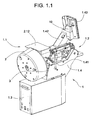
- Fig. 1.1 shows the inventive device for Tüllenbe conductedung, hereinafter called Tüllenbe conferenceer 1, consisting of a Tüllenmodul 1.1, a component module 1.2, a controller 1.3 and a base module 1.4.
- Assembly module 1.2 and control 1.3 are part of the base module 1.4.
- the grommet module 1.1 is separable by means of lever 1.41 from the base module 1.4.
- On the base module 1.4 is also a boom 1.42 with a control panel 1.43 and an ejector 10th
- Fig. 1.2 shows the Tüllenbe Divisioner 1 with detached sleeve module 1.1, which is in operation by means of a serving as a guide and holding device centering pin 1.11 in connection with the base module 1.4 and which is separable by means of lever 1.41 of the base module 1.4.
- the Tüllenmodul 1.1 consists essentially of a Tüllen amid 2 with a rotatable drum 2.1, a hopper 2.11 with cover 2.12, a support 3 for receiving the tulle-specific machine parts 11,30,31,34,41,42 and / or tools and a conveyor consisting from a conveyor belt 7 carrying a linear vibrating conveyor 4.
- a arranged on the base module 1.4 drive 5 offset the drum 2.1 in a rotational movement.
- the conveyor rail 7 is tulle-specific or fits only for tulle varieties of the same geometry. (Spouts with the same geometry and different colors).
- conveying blades are arranged by means of which grommets 17 for the assembly of electrical cables of the conveyor rail 7 can be fed, wherein the in Fig. 2 Further described conveyor rail 7 protrudes through an open end of the Tüllen shalls 2 at the higher end in this.
- the drum 2.1 is preferably made of transparent plastic, so that a visual control of Tüllenvorrates and the feeding process is possible.
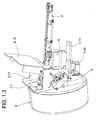
- Fig. 1.3 Below the centering 1.11 is a negative plug 1.12 is arranged, the pneumatic and electrical lines of Tüllenmoduls 1.1 via positive plug 1.16 of the base module 1.4 connects with pneumatic and electrical lines of the base module 1.4.
- Fig. 1.3 it can be seen that the drum 2.1 is tilted slightly downwards relative to the conveyor rail 7 on the grommet module 1.1. As a result of gravity, the grommets 17 in the drum always move toward the lower end of the drum 2, the feed vanes exhausting the drum to the last grommet and feeding the conveyor rail 7 arranged at the higher end of the drum 2.1.
- Fig. 1.4 shows the Tüllenmodul 1.1 with the Tüllenmodul 1.1 separate drum 2.1.
- the drum 2.1 can be placed on a drive flange 1.13 of the sleeve module 1.1 and locked by means of a quick release 2.13 with the drive flange 1.13.
- the one end of the conveyor rail 7 protrudes at the higher end of the drum 2.1 in the drum 2.1.
- the Spouts 17 conveyed to the conveyor rail 7 by means of the conveyor blades are sorted in the correct position by a device 7.1, with the false grommets 17 being removed from the conveyor rail 7 by blowing away.
- Fig. 1.5 shows the patch module 1.1 placed on the base module 1.4 without the reservoir 2 and the funnel 2.11.
- the drive 5 is rotatably mounted about an axis 5.11 in the direction of arrow P1, wherein the drive 5 is pivotable in the direction of arrow P1 against a spring force.
- a pinion 5.12 engages automatically after a change of Tüllenmoduls 1.1 in the teeth of a ring gear 1.14, wherein the ring gear 1.14 drives the drive flange 1.13.
- Centering pin 1.11, plug-in device 1.12, drive flange 1.13, ring gear 1.14, hopper 2.11, carrier 3 and vibratory conveyor 4 are arranged on a housing 1.15 of Tüllenmoduls 1.1.
- the housing 1.15 closes off the drum 2.1 by means of a flange, together they form the tulle storage 2.
- Fig. 1.6 shows a receiving device 1.44 for receiving the centering pin 1.11.
- the receiving device 1.44 essentially comprises a housing 1.45 with a bore 1.46 into which the centering pin 1.11 fits.
- a circular notch 1.47 is provided, which fits on an actuatable bolt 1.48.
- the centering pin 1.11 is pushed into the hole 1.46 until the notch 1.47 is the same as the pin 1.48.
- bolt 1.48 is moved by lever 1.41 and lever linkage 1.49 into notch 1.47, with the releasable notch / bolt connection pushing and holding the grommet module 1.1 in the correct axial position. All Electric and pneumatic lines are also coupled when inserting the centering pin 1.11 (by means of plug-in device 1.12,1.16).
- the conveyor rail 7 in the longitudinal direction of a groove 16 whose cross-section approximately to the outline of the longitudinal section of a spout 17 (FIG. Fig. 4a-4e ) corresponds.
- the groove 16 is open at the rear end 18 of the conveyor rail 7, while it is closed at the front end 19 ( Fig. 4a-4e ).
- the front in the conveying direction P2 part of the groove 16 serves as a buffer 20, in which the spouts are stored in the correct position and which is covered with a cover plate 21.
- the cover plate 21 covers the groove 16 in half, so that the stored spouts are visible.
- the cover plate 21 has a projection 21.1 which completely covers the groove 16.
- the front end 19 of the conveyor rail 7 is covered with a plate 22 in which a bore 23 is provided, whose axis coincides with the axis of the first spout in the buffer 20.
- a vertical bore 24 (FIG. Fig. 4a-4e ) is provided in the conveyor rail 7, whose axis also coincides with the axis of the first spout, and whose diameter is smaller than that of the spout 17.
- a sorting baffle 25 is provided with a groove 16 on one side interrupting recess 26 and a Ausblasdüse not shown. At 28 is arranged upstream of the sorting baffle 25 blowing nozzle.
- a light barrier is connected, whose light beam is symbolized by a dot-dash line 29.
- the rail may be provided with a plurality of parallel, obliquely to the conveying direction in the feed opening holes through which exits a continuous adjustable air flow.
- Fig. 3 . Fig. 3a show details of the assembly module 1.2.
- the ejection device 10 has a centering pin 30 that can be moved up and down, which can be driven pneumatically, for example.
- the rotating device 11, which is arranged below the conveyor rail 7, has four mandrels 31, which are offset by an angle of 90 ° from each other.
- the rotating device 11 can be further rotated stepwise by an angle of 90 ° by means of a stepping motor 32.
- the mandrels 31 have two different diameters, wherein the diameter in the region of the tip of the mandrel is the smaller.
- the rotary device 11 is arranged such that in each case a mandrel 31 in a first position I of the rotary device 11 with the vertical bore 24 (FIG. Fig. 4a-4e ) of the conveyor rail 7 is aligned.
- a Aufschiebetician is referred to, which has two mold plates 34, in each of which a half of a bore 35 is arranged, which is aligned in a second position II of the rotating device 11 each with a mandrel 31.
- the mold plates 34 are fastened to holders 36, which are pivotable about pivot points 37 and are resiliently connected to a carrier 39 via a spring 38.
- the slide-on unit 33 can be moved in a straight line (for example pneumatically) in the direction of the mandrel 31.
- An insertion head 40 has a spout receiving part 41 and a spreading part 42.
- the Tüllenfactteil 41 consists of two jaws 43, each having a half of a cylindrical recess 44, whose size is adapted to the shape of the spouts 17 to be processed.
- the jaws 43 are arranged radially in opposite directions (for example pneumatically) displaceable on a guide support 45.
- the expanding part 42 consists of two further jaws 46, each having one half of a sleeve-shaped projection 47 and a bore 48 extending therethrough.
- the bore 48 has on the side facing away from the sleeve-shaped projection 47 of the other jaws 46 a funnel-shaped extension 49 and is dimensioned so that the cable 13 to be assembled can be accommodated.
- the further jaws 46 are slidably disposed on a further guide support 50, wherein they are moved simultaneously with the jaws 43, for which purpose they are mechanically coupled to the jaws 43.
- the Tüllenabilityteil 41 and the Aufsp Sonteil 42 are arranged such that the cylindrical recess 44 and the bore 48 in a further position IV of the rotating device 11 are aligned with one of the mandrels 31, wherein the further position IV relative to the second position II by an angle of 180 ° is offset.
- the Tüllenabilityteil 41 is disposed within a U-shaped recess 50.1 of the other guide support 50 in the axial direction of the cylindrical recess 44 (for example, pneumatically) slidably.
- the further guide member 50 is connected to a housing 51 which can be displaced in the axial direction of the cylindrical recess 44 and bore 48 together with the Tüllenabilityteil 41 and the expanding part 42 (also, for example, pneumatically).
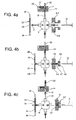
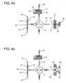
- a cable 13 is equipped with a grommet 17 as follows: After the grommets 17 are stored in the correct position on the conveyor rail 7, the foremost grommet 17 in the buffer 20 is conveyed via the vertical bore 24 ( Fig. 4d ). The spout 17 is now by means of the centering mandrel 30th pushed the ejector 10 on the tip of a mandrel 31 in the first position I ( Fig. 4a, 4b ). At the same time a seated on a position in the second position II mandrel 31 seated grommet 17 is pushed by the Aufschiebeech 33 on the thicker part of the mandrel 31, whereby it is expanded and placed in the correct position.
- the spreading member 42 is displaced relative to the Tüllenfactteil 41, wherein the spout 17 is stripped and clamped on the cable 13 ( Fig. 4d ). Thereafter, the jaws open 43 and 46, so that the assembled cable 13 can be removed and a new can be supplied.
- the rotating device 11 rotates through an angle of 90 °, wherein the empty mandrel 31 are rotated in the first position I and the already equipped mandrels 31 in the second and the other position II or IV ( Fig. 4e ).
- the tulle applicator 1 is converted as follows:
- the Tüllenmodul 1.1 contains all the items that are necessary for the assembly of the cable 13 with spouts of a particular Tüllensorte.
- Tüllen Entifacts
- Tüllen Entifacts
- the tulle-specific machine parts 11, 30, 31, 34, 41, 42 are arranged on the carrier 3.
- Tüllenmodul 1.1 is placed on the base module 1.4 (with corresponding spouts and tulle-specific machine parts and with the tulle-specific conveyor rail 7) and locked by means of levers 1.41.
- the centering 1.11 is plugged into a receptacle 1.44 of the base module 1.4, wherein all electrical and pneumatic lines are also coupled (by means of plug-in device 1.12,1.16).
- the grommet module 1.1 With the lever 1.41, the grommet module 1.1 is in the right place Axial position pressed and held.
- the coupling of the drive pinion 5.12 with the ring gear 1.14 is carried out automatically by means of the radially sprung drive 5.
- the tulle-specific machine parts 11,30,31,34,41,42 are mounted without tools.
- the quick release 2.13 of the drum 2.1 is opened before dropping the Tüllenmoduls 1.1.
- the spout module 1.1 (without drum) can be lifted out of the drum guide and inserted into a drum 2.1 with identical but differently colored spouts 17.
- the further assembly process is carried out as described above, except that the tulle-specific machine parts 11,30,31,34,41,42 are already mounted.
Description
- Die Erfindung betrifft eine Einrichtung zur Tüllenbestückung von elektrischen Kabeln bestehend aus einem Basismodul zum Tragen eines Tüllenmoduls und eines Bestückungsmoduls, wobei das Tüllenmodul die zu bestückenden Tüllen lagerichtig dem Bestückungsmodul bereitstellt und das Bestückungsmodul die Kabel mit den Tüllen bestückt.
- Aus der
Patentschrift EP 0 626 738 B1 ist eine Einrichtung zur Tüllenbestückung von elektrischen Kabeln bekannt geworden. Mit derartigen Einrichtungen können Tüllen, die beispielsweise für feuchtigkeitsdichte Durchführungen von elektrischen Kabeln durch Gehäusewände von Elektroapparaten benötigt werden, rationell auf die Kabel aufgeschoben werden. Die Einrichtung besteht aus einer an einer Stirnseite offenen, mit Tüllen füllbaren Trommel, welche um eine schräg zur Horizontalen verlaufenden Achse antreibbar ist. Im Innern der Trommel angeordnete Schaufeln übergeben einer in die Trommel hineinragenden Förderschiene bei drehender Trommel Tüllen zum Zwecke der lagerichtigen Speicherung und Weiterbeförderung. Eine Ausstossvorrichtung mit einem auf und ab bewegbaren Zentrierdorn führt jeweils die erste Tülle in der Förderschiene einer Drehvorrichtung zu, die mehrere Dorne aufweist und schrittweise um einen bestimmten Winkel weiterdrehbar ist, wobei in einer ersten Stellung der Drehvorrichtung jeweils eine Tülle auf die Spitze eines Dornes geschoben wird. In einer zweiten Stellung der Drehvorrichtung wird mittels einer Aufschiebeeinheit die Tülle zum Zwecke des Aufweitens auf einen Teil des Dornes geschoben. In einer weiteren Stellung der Drehvorrichtung wird mittels eines Bestückungskopfes mit Tüllenaufnahmeteil und Aufspreizteil die Tülle vom Dorn abgezogen und die Tülle im aufgeweiteten Zustand auf das Kabel geschoben. - Ein Nachteil der bekannten Einrichtung liegt darin, dass beim Umrüsten der Einrichtung von einer Tüllensorte auf eine andere Tüllensorte viele tüllenspezifische Maschinenteile oder Werkzeuge ausgetauscht werden müssen, was lange Umrüstzeiten verursacht.
- Hier will die Erfindung Abhilfe schaffen. Die Erfindung, wie sie in Anspruch 1 gekennzeichnet ist, löst die Aufgabe, die Nachteile der bekannten Einrichtung zu vermeiden und eine Einrichtung zur Tüllenbestückung zu schaffen, die einfach und schnell umrüstbar ist.
- Vorteilhafte Weiterbildungen der Erfindung sind in den abhängigen Patentansprüchen angegeben.
- Die durch die Erfindung erreichten Vorteile sind im wesentlichen darin zu sehen, dass beim Umrüsten der Einrichtung Fehlerquellen ausgeschlossen werden. Bei der erfindungsgemässen Einrichtung werden im wesentlichen nicht mehr einzelne tüllenspezifische Teile oder Werkzeuge ausgetauscht, sondern tüllenspezifische Module oder Untermodule. Die Verwechslungsgefahr beim Umrüsten wird dadurch drastisch gesenkt. Ausserdem wird die Umrüstzeit und somit die Stillstandszeit der Maschine beim Wechsel auf eine andere Tüllensorte wesentlich verkürzt. Das Tüllenmodul für die Bestückung des nachfolgenden Kabelloses kann während der Bestückung des laufenden Kabelloses vollständig vorbereitet werden. Mit kurzen Umrüstzeiten können selbst kleine Kabellose kostengünstig produziert werden.
- Anhand der beiliegenden Figuren wird die vorliegende Erfindung näher erläutert.
- Es zeigen:
-
Fig. 1.1
ein erfindungsgemässer Tüllenbestücker, -
Fig. 1.2
den Tüllenbestücker mit losgelöstem Tüllenmodul, -
Fig. 1.3
das Tüllenmodul mit geöffnetem Speicherdeckel, -
Fig. 1.4
das Tüllenmodul mit abnehmbarem Tüllenspeicher, -
Fig. 1.5
das Tüllenmodul ohne Speicher, -
Fig. 1.6
eine Aufnahmeeinrichtung für das Tüllenmodul, -
Fig. 2
eine Förderschiene des Tüllenmoduls, -
Fig. 3 ,Fig. 3a
ein Bestückungsmodul und -
Fig. 4a bis 4e
eine Darstellung des Vorganges zur Bestückung von Kabeln mit Tüllen. -
Fig. 1.1 zeigt die erfindungsgemässe Einrichtung zur Tüllenbestückung, im weiteren Tüllenbestücker 1 genannt, bestehend aus einem Tüllenmodul 1.1, einem Bestückungsmodul 1.2, einer Steuerung 1.3 und einem Basismodul 1.4. Bestückungsmodul 1.2 und Steuerung 1.3 sind Teil des Basismoduls 1.4. Das Tüllenmodul 1.1 ist mittels Hebel 1.41 vom Basismodul 1.4 trennbar. Am Basismodul 1.4 angeordnet ist auch ein Ausleger 1.42 mit einem Bedientableau 1.43 und einer Ausstossvorrichtung 10. -
Fig. 1.2 zeigt den Tüllenbestücker 1 mit losgelöstem Tüllenmodul 1.1, das im Betrieb mittels eines als Führungs-und Halteeinrichtung dienenden Zentrierzapfens 1.11 in Verbindung mit dem Basismodul 1.4 steht und das mittels Hebel 1.41 vom Basismodul 1.4 trennbar ist. Das Tüllenmodul 1.1 besteht im wesentlichen aus einem Tüllenspeicher 2 mit einer rotierbaren Trommel 2.1, einem Einfülltrichter 2.11 mit Deckel 2.12, einem Träger 3 zur Aufnahme der tüllenspezifischen Maschinenteile 11,30,31,34,41,42 und/oder Werkzeuge und einer Fördereinrichtung bestehend aus einem eine Förderschiene 7 tragenden, linearen Schwingförderer 4. Ein am Basismodul 1.4 angeordneter Antrieb 5 versetzt die Trommel 2.1 in eine Rotationsbewegung. - Die Förderschiene 7 ist tüllenspezifisch bzw. passt nur für Tüllensorten gleicher Geometrie. (Tüllen mit gleicher Geometrie und unterschiedlichen Farben).
- Im Innern der Trommel 2.1 sind nicht dargestellte Förderschaufeln angeordnet, mittels denen Tüllen 17 für die Bestückung von elektrischen Kabeln der Förderschiene 7 zuführbar sind, wobei die in
Fig. 2 näher beschriebene Förderschiene 7 durch eine offene Stirnseite des Tüllenspeichers 2 am höher gelegenen Ende in diesen hineinragt. Die Trommel 2.1 ist vorzugsweise aus transparentem Kunststoff gefertigt, so dass eine optische Kontrolle des Tüllenvorrates und des Zuführvorganges möglich ist. -
Fig. 1.3 zeigt das Tüllenmodul 1.1 mit geöffnetem Speicherdeckel 2.12 zum Beschicken des Tüllenspeichers 2. Unterhalb des Zentrierzapfens 1.11 ist eine negative Steckeinrichtung 1.12 angeordnet, die pneumatische und elektrische Leitungen des Tüllenmoduls 1.1 via positiver Steckeinrichtung 1.16 des Basismoduls 1.4 mit pneumatischen und elektrischen Leitungen des Basismoduls 1.4 verbindet. Wie ausFig. 1.3 ersichtlich, ist die Trommel 2.1 gegenüber der Förderschiene 7 leicht nach unten gekippt am Tüllenmodul 1.1 angeordnet. Schwerkraftbedingt bewegen sich die Tüllen 17 in der Trommel immer dem tieferliegenden Ende der Trommel 2 zu, wobei die Förderschaufeln die Trommel bis zur letzten Tülle ausschöpfen und der am höherliegenden Ende der Trommel 2.1 angeordneten Förderschiene 7 zuführen. -
Fig. 1.4 zeigt das Tüllenmodul 1.1 mit vom Tüllenmodul 1.1 getrennter Trommel 2.1. Die Trommel 2.1 ist auf einen Antriebsflansch 1.13 des Tüllenmoduls 1.1 aufsetzbar und mittels eines Schnellverschlusses 2.13 mit dem Antriebsflansch 1.13 verriegelbar. Wie ausFig. 1.4 ersichtlich, ragt das eine Ende der Förderschiene 7 am höherliegenden Ende der Trommel 2.1 in die Trommel 2.1. Die mittels der Förderschaufeln auf die Förderschiene 7 geförderten Tüllen 17 werden von einer Einrichtung 7.1 lagerichtig sortiert, wobei die falschliegenden Tüllen 17 durch Wegblasen von der Förderschiene 7 entfernt werden. -
Fig. 1.5 zeigt das auf das Basismodul 1.4 aufgesetzte Tüllenmodul 1.1 ohne Tüllenspeicher 2 und Einfülltrichter 2.11. Wie ausFig. 1.5 ersichtlich, ist der Antrieb 5 um eine Achse 5.11 in Pfeilrichtung P1 drehbar gelagert, wobei der Antrieb 5 in Pfeilrichtung P1 entgegen einer Federkraft schwenkbar ist. Mit der federnden Lagerung des Antriebs 5 rastet ein Ritzel 5.12 nach einem Wechsel des Tüllenmoduls 1.1 selbsttätig in die Zähne eines Zahnkranzes 1.14 ein, wobei der Zahnkranz 1.14 den Antriebsflansch 1.13 antreibt. - Zentrierzapfen 1.11, Steckeinrichtung 1.12, Antriebsflansch 1.13, Zahnkranz 1.14, Einfülltrichter 2.11, Träger 3 und Schwingförderer 4 sind an einem Gehäuse 1.15 des Tüllenmoduls 1.1 angeordnet. Das Gehäuse 1.15 schliesst die Trommel 2.1 mittels Flansch ab, zusammen bilden sie den Tüllenspeicher 2.
-
Fig. 1.6 zeigt eine Aufnahmeeinrichtung 1.44 zur Aufnahme des Zentrierzapfens 1.11. Die Aufnahmeeinrichtung 1.44 umfasst im wesentlichen ein Gehäuse 1.45 mit einer Bohrung 1.46, in die der Zentrierzapfen 1.11 passt. Am Zentrierzapfen 1.11 ist eine kreisrunde Kerbe 1.47 vorgesehen, die auf einen betätigbaren Bolzen 1.48 passt. Der Zentrierzapfen 1.11 wird soweit in die Bohrung 1.46 geschoben, bis die Kerbe 1.47 gleichliegend mit dem Bolzen 1.48 ist. Dann wird der Bolzen 1.48 mittels Hebel 1.41 und Hebelgestänge 1.49 in die Kerbe 1.47 bewegt, wobei die lösbare Kerben-/Bolzenverbindung das Tüllenmodul 1.1 in die richtige achsiale Position drückt und festhält. Alle Elektro- und Pneumatikleitungen werden beim Einschieben des Zentrierzapfens 1.11 ebenfalls (mittels Steckeinrichtung 1.12,1.16) gekoppelt. - Wie in
Fig. 2 gezeigt weist die Förderschiene 7 in Längsrichtung eine Nut 16 auf, deren Querschnitt annähernd dem Umriss des Längsschnittes einer Tülle 17 (Fig. 4a-4e ) entspricht. Die Nut 16 ist am hinteren Ende 18 der Förderschiene 7 offen, während sie am vorderen Ende 19 geschlossen ist (Fig. 4a-4e ). Der in Förderrichtung P2 vordere Teil der Nut 16 dient als Puffer 20, in welchem die Tüllen lagerichtig gespeichert sind und der mit einem Deckblech 21 abgedeckt ist. Das Deckblech 21 deckt die Nut 16 zur Hälfte ab, so dass die gespeicherten Tüllen sichtbar sind. Am Puffereinlauf weist das Deckblech 21 einen Vorsprung 21.1 auf, der die Nut 16 vollständig überdeckt. Das vordere Ende 19 der Förderschiene 7 ist mit einer Platte 22 abgedeckt, in der eine Bohrung 23 vorgesehen ist, deren Achse mit der Achse der ersten Tülle im Puffer 20 zusammenfällt. Unterhalb der ersten Tülle im Puffer 20 ist eine vertikale Bohrung 24 (Fig. 4a-4e ) in der Förderschiene 7 vorgesehen, deren Achse ebenfalls mit der Achse der ersten Tülle zusammenfällt, und deren Durchmesser kleiner als derjenige der Tülle 17 ist. Vor dem Puffereinlauf ist eine Sortierschikane 25 mit einer die Nut 16 an einer Seite unterbrechenden Aussparung 26 und einer nicht dargestellten Ausblasdüse vorgesehen. Mit 28 ist eine vor der Sortierschikane 25 angeordnete Abblasdüse bezeichnet. Hinter dem Puffereinlauf ist eine nicht weiter dargestellte Lichtschranke angeschlossen, deren Lichtstrahl durch eine strichpunktierte Linie 29 symbolisiert ist. Zur Verbesserung der Förderung kann die Schiene mit mehreren parallelen, schräg zur Förderrichtung in die Fördernut mündenden Bohrungen versehen sein, durch welche ein kontinuierlicher einstellbarer Luftstrom austritt. -
Fig. 3 ,Fig. 3a zeigen Einzelheiten des Bestückungsmoduls 1.2. Wie inFig. 1.1 ,Fig. 3 undFig. 3a gezeigt ist die Ausstossvorrichtung 10 oberhalb der Förderschiene 7 in der Achse der einen Bohrung 23 (Fig. 2 ) und der vertikalen Bohrung 24 (Fig. 4a-4e ) verlaufend angeordnet. Die Ausstossvorrichtung 10 weist einen auf und ab bewegbaren Zentrierdorn 30 auf, der beispielsweise pneumatisch antreibbar ist. Die Drehvorrichtung 11, die unterhalb der Förderschiene 7 angeordnet ist, weist vier Dorne 31 auf, die um einen Winkel von 90° voneinander versetzt sind. Die Drehvorrichtung 11 kann mittels eines Schrittmotores 32 schrittweise um einen Winkel von 90° weitergedreht werden. Die Dorne 31 weisen zwei verschiedene Durchmesser auf, wobei der Durchmesser im Bereiche der Spitze des Dornes der kleinere ist. Die Drehvorrichtung 11 ist derart angeordnet, dass jeweils ein Dorn 31 in einer ersten Stellung I der Drehvorrichtung 11 mit der vertikalen Bohrung 24 (Fig. 4a-4e ) der Förderschiene 7 fluchtet. Mit 33 ist eine Aufschiebeeinheit bezeichnet, die zwei Formplatten 34 aufweist, in welchen je eine Hälfte einer Bohrung 35 angeordnet ist, die in einer zweiten Stellung II der Drehvorrichtung 11 jeweils mit einem Dorn 31 fluchtet. Die Formplatten 34 sind an Haltern 36 befestigt, die um Gelenkpunkte 37 schwenkbar sind und über eine Feder 38 federnd mit einem Träger 39 verbunden sind. Die Aufschiebeeinheit 33 kann (beispielsweise pneumatisch) in Richtung des Dornes 31 geradlinig verschoben werden. - Ein Bestückungskopf 40 weist ein Tüllenaufnahmeteil 41 und ein Aufspreizteil 42 auf. Das Tüllenaufnahmeteil 41 besteht aus zwei Backen 43, die je eine Hälfte einer zylindrischen Ausnehmung 44 aufweisen, deren Grösse der Form der zu verarbeitenden Tüllen 17 angepasst ist. Die Backen 43 sind radial gegenläufig (beispielsweise pneumatisch) verschiebbar auf einem Führungsträger 45 angeordnet. Das Aufspreizteil 42 besteht aus zwei weiteren Backen 46, die je eine Hälfte eines hülsenförmigen Ansatzes 47 und einer durch diesen verlaufende Bohrung 48 aufweisen. Die Bohrung 48 weist an der dem hülsenförmigen Ansatz 47 abgewandten Seite der weiteren Backen 46 eine trichterförmige Erweiterung 49 auf und ist so bemessen, dass das zu bestückende Kabel 13 aufgenommen werden kann. Die weiteren Backen 46 sind verschiebbar auf einem weiteren Führungsträger 50 angeordnet, wobei sie gleichzeitig mit den Backen 43 verschoben werden, zu welchem Zweck sie mit den Backen 43 mechanisch gekoppelt sind. Das Tüllenaufnahmeteil 41 und das Aufspreizteil 42 sind derart angeordnet, dass die zylindrische Ausnehmung 44 und die Bohrung 48 in einer weiteren Stellung IV der Drehvorrichtung 11 mit einem der Dorne 31 fluchten, wobei die weitere Stellung IV gegenüber der zweiten Stellung II um einen Winkel von 180° versetzt ist. Das Tüllenaufnahmeteil 41 ist innerhalb einer u-förmigen Ausnehmung 50.1 des weiteren Führungsträgers 50 in Achsrichtung der zylindrischen Ausnehmung 44 (beispielsweise pneumatisch) verschiebbar angeordnet. Das weitere Führungsteil 50 ist mit einem Gehäuse 51 verbunden, das in Achsrichtung der zylindrischen Ausnehmung 44 und Bohrung 48 zusammen mit dem Tüllenaufnahmeteil 41 und dem Aufspreizteil 42 (ebenfalls beispielsweise pneumatisch) verschoben werden kann.
- Ein Kabel 13 wird wie folgt mit einer Tülle 17 bestückt: Nachdem die Tüllen 17 lagerichtig auf der Förderschiene 7 gespeichert sind wird jeweils die vorderste Tülle 17 im Puffer 20 über die vertikale Bohrung 24 gefördert (
Fig. 4d ). Die Tülle 17 wird nun mittels des Zentrierdornes 30 der Ausstossvorrichtung 10 auf die Spitze eines in der ersten Stellung I befindlichen Dornes 31 geschoben (Fig. 4a, 4b ). Gleichzeitig wird eine auf einem in der zweiten Stellung II befindlichen Dorn 31 sitzende Tülle 17 mittels der Aufschiebeeinheit 33 auf den dickeren Teil des Dornes 31 geschoben, womit sie aufgeweitet und in die richtige Position gebracht wird. Da die Bohrung 35 kleiner als der Dorn 31 ist, werden hierbei die Formplatten 34 entgegen einer Federkraft auseinandergedrückt (Fig. 4a, 4b ). Während der gleichen Zeit wird eine auf einem in der weiteren Stellung IV befindlichen Dorn 31 sitzende Tülle 17 von den Backen 43 des Tüllenaufnahmeteiles 41 umfasst, wobei auch die weiteren Backen 46 des Aufspreizteiles 42 geschlossen werden (Fig. 4a, 4b ). Dann wird der Zentrierdorn 30 der Ausstossvorrichtung 10 zurückgezogen und das Tüllenaufnahmeteil 41 mit der Tülle 17 gegen das Aufspreizteil 42 geschoben, wobei der hülsenförmige Ansatz 47 des Aufspreizteiles 42 in die Tüllenbohrung eindringt und die Tülle 17 nochmals etwas aufgeweitet wird (Fig. 4c ). Danach wird die Aufschiebeeinheit 33 zurückgeschoben, sowie die Tülle 17 mittels des Tüllenaufnahmeteiles 41 vom Dorn 31 abgezogen und in Richtung Kabel 13 transportiert. Hierbei wird die Tülle 17 vom Aufspreizteil 42 im aufgeweiteten Zustand gehalten bis die richtige Position auf dem Kabel 13 erreicht ist. Sodann wird das Aufspreizteil 42 relativ zum Tüllenaufnahmeteil 41 verschoben, wobei die Tülle 17 abgestreift wird und sich auf dem Kabel 13 festklemmt (Fig. 4d ). Danach öffnen sich die Backen 43 und 46, so dass das bestückte Kabel 13 entfernt und ein neues zugeführt werden kann. Gleichzeitig dreht sich die Drehvorrichtung 11 um einen Winkel von 90°, wobei der leere Dorn 31 in die erste Stellung I und die bereits bestückten Dorne 31 in die zweite und die weitere Stellung II bzw. IV gedreht werden (Fig. 4e ). - Bei einem Tüllenwechsel (Wechsel von einer Tüllensorte auf eine andere Tüllensorte mit Tüllen unterschiedlicher Farbe und/oder Tüllengeometrie) wird der Tüllenbestücker 1 wie folgt umgerüstet:
- Das Tüllenmodul 1.1 enthält alle Einzelteile, die für die Bestückung der Kabel 13 mit Tüllen einer bestimmten Tüllensorte notwendig sind. Tüllenspeicher 2 und justierte Förderschiene 7 sind vormontiert. Die tüllenspezifischen Maschinenteile 11,30,31,34,41,42 sind am Träger 3 angeordnet.
- Beim Wechsel des Tüllenmoduls 1.1 werden zuerst die tüllenspezifischen Maschinenteile 11,30,31,34,41,42 der bisherigen Tüllenbestückung werkzeuglos demontiert und am Träger 3 angeordnet. Danach wird mittels Hebel 1.41 das Tüllenmodul 1.1 entriegelt und nach hinten weggezogen. Dieses lässt sich mit der Trommel 2.1 nach unten lagestabil auf einer ebenen Auflage deponieren. Allfällig noch auf der Förderschiene 7 verbleibende Tüllen 17 fallen dadurch in die Trommel 2.1 zurück.
- Falls für das neue Bestückungslos Tüllen 17 mit vom bisherigen Bestückungslos unterschiedlicher Tüllengeometrie notwendig sind, wird ein komplettes Tüllenmodul 1.1 auf das Basismodul 1.4 (mit entsprechenden Tüllen und tüllenspezifischen Maschinenteilen sowie mit der tüllenspezifischen Förderschiene 7) aufgesetzt und mittels Hebel 1.41 verriegelt. Der Zentrierzapfen 1.11 wird dazu in eine Aufnahmeeinrichtung 1.44 des Basismoduls 1.4 gesteckt, wobei alle Elektro- und Pneumatikleitungen ebenfalls (mittels Steckeinrichtung 1.12,1.16) gekoppelt werden. Mit dem Hebel 1.41 wird des Tüllenmodul 1.1 in die richtige achsiale Position gedrückt und festgehalten. Die Kopplung des Antriebsritzels 5.12 mit dem Zahnkranz 1.14 erfolgt selbsttätig mittels des radial gefederten Antriebs 5. Abschliessend werden noch die tüllenspezifischen Maschinenteile 11,30,31,34,41,42 werkzeuglos montiert.
- Falls für das neue Bestückungslos Tüllen 17 mit vom bisherigen Bestückungslos unterschiedlicher Tüllenfarbe notwendig sind, wird vor dem Ablegen des Tüllenmoduls 1.1 der Schnellverschluss 2.13 der Trommel 2.1 geöffnet. Nach dem Ablegen und wenn sich alle Tüllen 17 in der Trommel 2.1 befinden, kann das Tüllenmodul 1.1 (ohne Trommel) aus der Trommelführung angehoben und in eine Trommel 2.1 mit formgleichen, aber andersfarbigen Tüllen 17 gesteckt werden. Der weitere Montagevorgang erfolgt wie weiter oben beschrieben, ausser dass die tüllenspezifischen Maschinenteile 11,30,31,34,41,42 bereits montiert sind.
Claims (10)
- Einrichtung zur Tüllenbestückung von elektrischen Kabeln (13) bestehend aus einem Basismodul (1.4) zum Tragen eines Tüllenmoduls (1.1) und eines Bestückungsmoduls (1.2), wobei das Tüllenmodul (1.1) die zu bestückenden Tüllen (17) lagerichtig dem Bestückungsmodul (1.2) bereitstellt und das Bestückungsmodul (1.2) die Kabel (13) mit den Tüllen (17) bestückt,
dadurch gekennzeichnet,
dass das aus Tüllenspeicher (2) und Fördereinrichtung (4,7) bestehende Tüllenmodul (1.1) steckbar am Basismodul (1.4) anbringbar ist. - Einrichtung nach Anspruch 1,
dadurch gekennzeichnet,
dass das Tüllenmodul (1.1) ein Gehäuse (1.15) aufweist an dem eine Führungs- und Halteeinrichtung (1.11) angeordnet ist, die in eine Aufnahmeeinrichtung (1.44) des Basismoduls (1.4) passt. - Einrichtung nach Anspruch 2,
dadurch gekennzeichnet,
dass die Führungs- und Halteeinrichtung einen Zentrierzapfen (1.11) mit Kerbe (1.47) aufweist. - Einrichtung nach einem der Ansprüche 2 oder 3,
dadurch gekennzeichnet,
dass die Aufnahmeeinrichtung (1.44) ein Gehäuse (1.45) mit Bohrung (1.46) aufweist, in die der Zentrierzapfen (1.11) mit Kerbe (1.47) passt, wobei die Kerbe (1.47) gleichliegend mit einem Bolzen (1.48) ist und der Bolzen (1.48) mittels Hebel (1.41) und Hebelgestänge (1.49) in die Kerbe (1.47) bewegbar ist. - Einrichtung nach einem der vorhergehenden Ansprüche,
dadurch gekennzeichnet,
dass am Gehäuse (1.15) ein mittels Zahnkranz (1.14) antreibbarer Antriebsflansch (1.13) angeordnet ist, an dem eine Trommel (2.1) des Tüllenspeichers (2) steckbar anbringbar ist. - Einrichtung nach Anspruch 5,
dadurch gekennzeichnet,
dass der Zahnkranz (1.14) mittels eines am Basismodul (1.4) angeordneten Antriebes (5) antreibbar ist. - Einrichtung nach einem der vorhergehenden Ansprüche,
dadurch gekennzeichnet,
dass am Gehäuse (1.15) eine negative Steckeinrichtung (1.12) angeordnet ist, die die pneumatischen und elektrischen Leitungen des Tüllenmoduls (1.1) via einer positiven Steckeinrichtung (1.16) des Basismoduls (1.4) mit pneumatischen und elektrischen Leitungen des Baismoduls (1.4) verbindet. - Einrichtung nach einem der vorhergehenden Ansprüche,
dadurch gekennzeichnet,
dass Gehäuse (1.15) einen Träger (3) zur Aufnahme tüllenspezifischer Maschinenteile (11,30,31,34,41,42) aufweist. - Einrichtung nach einem der vorhergehenden Ansprüche,
dadurch gekennzeichnet,
dass die tüllenspezifischen Maschinenteile (11,30,31,34,41,42) werkzeuglos am Bestückungsmodul (1.2) anbringbar und entfernbar sind. - Einrichtung nach einem der vorhergehenden Ansprüche,
dadurch gekennzeichnet,
dass am Gehäuse (1.15) als Fördereinrichtung ein eine Förderschiene (7) tragender Schwingförderer (4) angeordnet ist.
Priority Applications (1)
| Application Number | Priority Date | Filing Date | Title |
|---|---|---|---|
| EP20060101224 EP1689049B1 (de) | 2005-02-07 | 2006-02-02 | Einrichtung zur Tüllenbestückung von elektrischen Kabeln |
Applications Claiming Priority (2)
| Application Number | Priority Date | Filing Date | Title |
|---|---|---|---|
| EP05405058 | 2005-02-07 | ||
| EP20060101224 EP1689049B1 (de) | 2005-02-07 | 2006-02-02 | Einrichtung zur Tüllenbestückung von elektrischen Kabeln |
Publications (2)
| Publication Number | Publication Date |
|---|---|
| EP1689049A1 EP1689049A1 (de) | 2006-08-09 |
| EP1689049B1 true EP1689049B1 (de) | 2008-11-12 |
Family
ID=36642684
Family Applications (1)
| Application Number | Title | Priority Date | Filing Date |
|---|---|---|---|
| EP20060101224 Active EP1689049B1 (de) | 2005-02-07 | 2006-02-02 | Einrichtung zur Tüllenbestückung von elektrischen Kabeln |
Country Status (1)
| Country | Link |
|---|---|
| EP (1) | EP1689049B1 (de) |
Cited By (6)
| Publication number | Priority date | Publication date | Assignee | Title |
|---|---|---|---|---|
| WO2011158145A1 (de) | 2010-06-16 | 2011-12-22 | Schleuniger Holding Ag | Vorrichtung zum aufbringen von kabeltüllen auf ein kabel |
| EP2731207A1 (de) | 2012-11-07 | 2014-05-14 | Schleuniger Holding AG | Vorrichtung zum Aufbringen von Kabeltüllen auf ein Kabel |
| US9352430B2 (en) | 2010-06-16 | 2016-05-31 | Schleuniger Holding Ag | Cable grommet fitting apparatus for cable |
| US9649737B2 (en) | 2012-09-12 | 2017-05-16 | Schleuniger Holding Ag | Machines and processes for fitting cable bushings |
| US9653865B2 (en) | 2011-09-29 | 2017-05-16 | Schleuniger Holding Ag | Method for fitting cables with cable sleeves |
| US11482823B2 (en) | 2018-11-06 | 2022-10-25 | Komax Holding Ag | Grommet station |
Families Citing this family (6)
| Publication number | Priority date | Publication date | Assignee | Title |
|---|---|---|---|---|
| EP1912296B1 (de) * | 2006-10-09 | 2011-06-08 | Komax Holding AG | Einrichtung und Verfahren zur Bestimmung der Lage einer Kabelbestückung an einem Kabel |
| US7963032B2 (en) | 2006-10-09 | 2011-06-21 | Komax Holding Ag | Method for determining the position of a wire fitting on a wire |
| EP3336976A1 (de) | 2016-12-16 | 2018-06-20 | Komax Holding Ag | Kabelbearbeitungseinrichtung |
| EP3970245B1 (de) * | 2019-05-17 | 2023-11-29 | Metzner Maschinenbau GmbH | Verfahren, vorrichtung und system zur konfektionierung eines elektrischen kabels |
| EP3819994A1 (de) | 2019-11-08 | 2021-05-12 | Schleuniger AG | Tüllenbereitstellungsmodul-träger |
| WO2023232217A1 (de) | 2022-06-02 | 2023-12-07 | Komax Holding Ag | Tüllenstation |
Family Cites Families (6)
| Publication number | Priority date | Publication date | Assignee | Title |
|---|---|---|---|---|
| US4653182A (en) * | 1984-04-17 | 1987-03-31 | Sumitomo Electric Industries, Ltd. | Apparatus for fitting terminals and rubber stoppers on wires |
| GB8917145D0 (en) * | 1989-07-27 | 1989-09-13 | Amp Gmbh | Applying a bung seal to an electrical lead |
| DE4019483C1 (de) * | 1990-06-19 | 1991-09-05 | Michels Gmbh & Co Kg, 4840 Rheda-Wiedenbrueck, De | |
| CH689272A5 (de) * | 1993-05-06 | 1999-01-15 | Komax Holding Ag | Einrichtung zur Tuellenbestueckung von elektrischen Kabeln. |
| DE59908252D1 (de) * | 1999-01-19 | 2004-02-12 | Pawo Systems Ag Unteraegeri | Verfahren und Einrichtung zur Tüllenbestückung |
| JP3706295B2 (ja) * | 2000-03-28 | 2005-10-12 | 矢崎総業株式会社 | ゴム栓挿入装置 |
-
2006
- 2006-02-02 EP EP20060101224 patent/EP1689049B1/de active Active
Cited By (8)
| Publication number | Priority date | Publication date | Assignee | Title |
|---|---|---|---|---|
| WO2011158145A1 (de) | 2010-06-16 | 2011-12-22 | Schleuniger Holding Ag | Vorrichtung zum aufbringen von kabeltüllen auf ein kabel |
| US9352430B2 (en) | 2010-06-16 | 2016-05-31 | Schleuniger Holding Ag | Cable grommet fitting apparatus for cable |
| US9496076B2 (en) | 2010-06-16 | 2016-11-15 | Schleuniger Holding Ag | Cable grommet fitting apparatus for cable |
| US9653865B2 (en) | 2011-09-29 | 2017-05-16 | Schleuniger Holding Ag | Method for fitting cables with cable sleeves |
| US9649737B2 (en) | 2012-09-12 | 2017-05-16 | Schleuniger Holding Ag | Machines and processes for fitting cable bushings |
| US10814450B2 (en) | 2012-09-12 | 2020-10-27 | Schleuniger Holding Ag | Processes for fitting cable bushings |
| EP2731207A1 (de) | 2012-11-07 | 2014-05-14 | Schleuniger Holding AG | Vorrichtung zum Aufbringen von Kabeltüllen auf ein Kabel |
| US11482823B2 (en) | 2018-11-06 | 2022-10-25 | Komax Holding Ag | Grommet station |
Also Published As
| Publication number | Publication date |
|---|---|
| EP1689049A1 (de) | 2006-08-09 |
Similar Documents
| Publication | Publication Date | Title |
|---|---|---|
| EP1689049B1 (de) | Einrichtung zur Tüllenbestückung von elektrischen Kabeln | |
| EP0626738B1 (de) | Einrichtung zur Tüllenbestückung von elektrischen Kabeln | |
| EP0956204B1 (de) | Verfahren zum einstecken von druckprodukten in ein gefaltetes hauptprodukt | |
| EP1022821B1 (de) | Verfahren und Einrichtung zur Tüllenbestückung | |
| DE102017105016B3 (de) | Lagervorrichtung | |
| EP0534106A1 (de) | Einrichtung für die Tüllenbestückung von elektrischen Kabeln | |
| EP2280878B1 (de) | Vorrichtung zum transportieren eines behälters | |
| DE102020127488A1 (de) | Vorrichtung zur automatisierten Herstellung von Schraubverbindungen | |
| DE4132998C2 (de) | Ansaug- und Transportvorrichtung | |
| EP3138778B1 (de) | Schalenverschliessmaschine | |
| DE102005029239B4 (de) | Artikel-Entladevorrichtung | |
| EP2492238A1 (de) | Vorrichtung zum Verschließen von Behältern | |
| EP3664959A1 (de) | Verfahren und vorrichtung zur bereitstellung von schrauben | |
| EP2709217B1 (de) | Maschine für die Montage von Kabeltüllen | |
| EP3651288B1 (de) | Tüllenstation | |
| DE2105333B2 (de) | Quetschmaschine | |
| DE102017102618B4 (de) | Zuführeinrichtung | |
| EP0661213B1 (de) | Etiketten-Einleger und Verfahren zum Betrieb desselben | |
| DE102015002502A1 (de) | Vorrichtung zum Wenden von formstabilen Behältern | |
| DE102009049806A1 (de) | Verfahren und Einrichtung zur elektrischen Isolationsprüfung sowie Verfahren und System zur Herstellung von Photovoltaikmodulen | |
| DE829570C (de) | Einrichtung an Tubenschliessmaschinen | |
| WO2020099085A1 (de) | Vorrichtung zum biegen stabförmiger werkstücke | |
| EP1162578A2 (de) | Vorrichtung zum Sortieren von Münzen mit einem als Hülsenbehälter ausgebildeten Münzenauffangbehälter | |
| EP1305135A1 (de) | Vorrichtung und verfahren zum laden eines nietmoduls mit blindnietmuttern | |
| DE102004001751B4 (de) | Farbzufuhrvorrichtung für Druckmaschinen |
Legal Events
| Date | Code | Title | Description |
|---|---|---|---|
| PUAI | Public reference made under article 153(3) epc to a published international application that has entered the european phase |
Free format text: ORIGINAL CODE: 0009012 |
|
| AK | Designated contracting states |
Kind code of ref document: A1 Designated state(s): AT BE BG CH CY CZ DE DK EE ES FI FR GB GR HU IE IS IT LI LT LU LV MC NL PL PT RO SE SI SK TR |
|
| AX | Request for extension of the european patent |
Extension state: AL BA HR MK YU |
|
| 17P | Request for examination filed |
Effective date: 20070122 |
|
| AKX | Designation fees paid |
Designated state(s): CH DE FR GB IT LI |
|
| GRAP | Despatch of communication of intention to grant a patent |
Free format text: ORIGINAL CODE: EPIDOSNIGR1 |
|
| GRAS | Grant fee paid |
Free format text: ORIGINAL CODE: EPIDOSNIGR3 |
|
| GRAA | (expected) grant |
Free format text: ORIGINAL CODE: 0009210 |
|
| AK | Designated contracting states |
Kind code of ref document: B1 Designated state(s): CH DE FR GB IT LI |
|
| REG | Reference to a national code |
Ref country code: GB Ref legal event code: FG4D Free format text: NOT ENGLISH |
|
| REG | Reference to a national code |
Ref country code: CH Ref legal event code: EP |
|
| REG | Reference to a national code |
Ref country code: CH Ref legal event code: NV Representative=s name: INVENTIO AKTIENGESELLSCHAFT |
|
| REF | Corresponds to: |
Ref document number: 502006002037 Country of ref document: DE Date of ref document: 20081224 Kind code of ref document: P |
|
| PLBI | Opposition filed |
Free format text: ORIGINAL CODE: 0009260 |
|
| PLAX | Notice of opposition and request to file observation + time limit sent |
Free format text: ORIGINAL CODE: EPIDOSNOBS2 |
|
| 26 | Opposition filed |
Opponent name: SCHLEUNIGER HOLDING AG Effective date: 20090811 |
|
| PLBB | Reply of patent proprietor to notice(s) of opposition received |
Free format text: ORIGINAL CODE: EPIDOSNOBS3 |
|
| GBPC | Gb: european patent ceased through non-payment of renewal fee |
Effective date: 20100202 |
|
| PG25 | Lapsed in a contracting state [announced via postgrant information from national office to epo] |
Ref country code: GB Free format text: LAPSE BECAUSE OF NON-PAYMENT OF DUE FEES Effective date: 20100202 |
|
| PLBP | Opposition withdrawn |
Free format text: ORIGINAL CODE: 0009264 |
|
| PLBD | Termination of opposition procedure: decision despatched |
Free format text: ORIGINAL CODE: EPIDOSNOPC1 |
|
| PLBM | Termination of opposition procedure: date of legal effect published |
Free format text: ORIGINAL CODE: 0009276 |
|
| STAA | Information on the status of an ep patent application or granted ep patent |
Free format text: STATUS: OPPOSITION PROCEDURE CLOSED |
|
| 27C | Opposition proceedings terminated |
Effective date: 20110806 |
|
| REG | Reference to a national code |
Ref country code: FR Ref legal event code: PLFP Year of fee payment: 11 |
|
| REG | Reference to a national code |
Ref country code: FR Ref legal event code: PLFP Year of fee payment: 12 |
|
| REG | Reference to a national code |
Ref country code: FR Ref legal event code: PLFP Year of fee payment: 13 |
|
| PGFP | Annual fee paid to national office [announced via postgrant information from national office to epo] |
Ref country code: FR Payment date: 20200219 Year of fee payment: 15 |
|
| PG25 | Lapsed in a contracting state [announced via postgrant information from national office to epo] |
Ref country code: FR Free format text: LAPSE BECAUSE OF NON-PAYMENT OF DUE FEES Effective date: 20210228 |
|
| PGFP | Annual fee paid to national office [announced via postgrant information from national office to epo] |
Ref country code: CH Payment date: 20230307 Year of fee payment: 18 |
|
| PGFP | Annual fee paid to national office [announced via postgrant information from national office to epo] |
Ref country code: IT Payment date: 20230220 Year of fee payment: 18 Ref country code: DE Payment date: 20230227 Year of fee payment: 18 |