EP1688655B1 - Flanschverbindung für Leitungen - Google Patents
Flanschverbindung für Leitungen Download PDFInfo
- Publication number
- EP1688655B1 EP1688655B1 EP05026821A EP05026821A EP1688655B1 EP 1688655 B1 EP1688655 B1 EP 1688655B1 EP 05026821 A EP05026821 A EP 05026821A EP 05026821 A EP05026821 A EP 05026821A EP 1688655 B1 EP1688655 B1 EP 1688655B1
- Authority
- EP
- European Patent Office
- Prior art keywords
- flange
- connection
- connection piece
- retaining means
- connection according
- Prior art date
- Legal status (The legal status is an assumption and is not a legal conclusion. Google has not performed a legal analysis and makes no representation as to the accuracy of the status listed.)
- Active
Links
- 239000000463 material Substances 0.000 claims description 9
- 238000007789 sealing Methods 0.000 claims description 7
- 238000005520 cutting process Methods 0.000 claims description 6
- 229910000831 Steel Inorganic materials 0.000 claims description 5
- 239000010959 steel Substances 0.000 claims description 5
- 238000009434 installation Methods 0.000 claims description 4
- 239000002184 metal Substances 0.000 claims description 4
- 229910052751 metal Inorganic materials 0.000 claims description 4
- 230000002093 peripheral effect Effects 0.000 description 7
- 238000004519 manufacturing process Methods 0.000 description 3
- RYGMFSIKBFXOCR-UHFFFAOYSA-N Copper Chemical compound [Cu] RYGMFSIKBFXOCR-UHFFFAOYSA-N 0.000 description 2
- 229910052802 copper Inorganic materials 0.000 description 2
- 239000010949 copper Substances 0.000 description 2
- UKGJZDSUJSPAJL-YPUOHESYSA-N (e)-n-[(1r)-1-[3,5-difluoro-4-(methanesulfonamido)phenyl]ethyl]-3-[2-propyl-6-(trifluoromethyl)pyridin-3-yl]prop-2-enamide Chemical compound CCCC1=NC(C(F)(F)F)=CC=C1\C=C\C(=O)N[C@H](C)C1=CC(F)=C(NS(C)(=O)=O)C(F)=C1 UKGJZDSUJSPAJL-YPUOHESYSA-N 0.000 description 1
- 238000010276 construction Methods 0.000 description 1
- 238000006073 displacement reaction Methods 0.000 description 1
- 230000007774 longterm Effects 0.000 description 1
- 238000002360 preparation method Methods 0.000 description 1
- 238000003825 pressing Methods 0.000 description 1
- 239000002994 raw material Substances 0.000 description 1
- 230000000284 resting effect Effects 0.000 description 1
- 239000011343 solid material Substances 0.000 description 1
- 125000006850 spacer group Chemical group 0.000 description 1
- 238000005482 strain hardening Methods 0.000 description 1
- 230000003313 weakening effect Effects 0.000 description 1
Images


Classifications
-
- F—MECHANICAL ENGINEERING; LIGHTING; HEATING; WEAPONS; BLASTING
- F16—ENGINEERING ELEMENTS AND UNITS; GENERAL MEASURES FOR PRODUCING AND MAINTAINING EFFECTIVE FUNCTIONING OF MACHINES OR INSTALLATIONS; THERMAL INSULATION IN GENERAL
- F16L—PIPES; JOINTS OR FITTINGS FOR PIPES; SUPPORTS FOR PIPES, CABLES OR PROTECTIVE TUBING; MEANS FOR THERMAL INSULATION IN GENERAL
- F16L5/00—Devices for use where pipes, cables or protective tubing pass through walls or partitions
- F16L5/02—Sealing
- F16L5/027—Sealing by means of a joint of the quick-acting type
-
- F—MECHANICAL ENGINEERING; LIGHTING; HEATING; WEAPONS; BLASTING
- F16—ENGINEERING ELEMENTS AND UNITS; GENERAL MEASURES FOR PRODUCING AND MAINTAINING EFFECTIVE FUNCTIONING OF MACHINES OR INSTALLATIONS; THERMAL INSULATION IN GENERAL
- F16L—PIPES; JOINTS OR FITTINGS FOR PIPES; SUPPORTS FOR PIPES, CABLES OR PROTECTIVE TUBING; MEANS FOR THERMAL INSULATION IN GENERAL
- F16L23/00—Flanged joints
- F16L23/02—Flanged joints the flanges being connected by members tensioned axially
- F16L23/024—Flanged joints the flanges being connected by members tensioned axially characterised by how the flanges are joined to, or form an extension of, the pipes
- F16L23/028—Flanged joints the flanges being connected by members tensioned axially characterised by how the flanges are joined to, or form an extension of, the pipes the flanges being held against a shoulder
- F16L23/0283—Flanged joints the flanges being connected by members tensioned axially characterised by how the flanges are joined to, or form an extension of, the pipes the flanges being held against a shoulder the collar being integral with the pipe
Definitions
- the present invention relates to a flange for pipes, in particular for sanitary installations, with a connecting piece, the end is in each case connected to a pipe for producing a sealed connection, and a flange which is disposed radially outwardly of the nozzle and fastening means on another component can be fixed to establish a connection between the nozzle and the other component.
- a flange connection for pipes is known in which in a sleeve on one side of a pipe end can be inserted and on the opposite side a flange connection is provided.
- the sleeve has a flanged end-side portion on which a disk-shaped flange can be applied.
- the flange is loose and must be pushed onto the sleeve during assembly. This is disadvantageous because a large number of individual parts have to be provided on the construction site in order to then assemble a flange connection.
- the flange has an opening through which the neck is made, wherein the flange is fixed on the neck via retaining means.
- the neck is flanged end and the radially projecting portion abuts against the flange.
- the flange is already fixed on this side by the protruding portion in the axial direction.
- the flange is fixed in the axial direction on the other side by the holding means, so that the flange is held captive on the neck.
- the flange can be latched to the holding means. Then the flange only needs to be pushed onto the holding means and is then held there.
- the holding means can form a ring, are formed on the radially projecting locking lugs, which secure the flange against axial displacement or against tilting at several points.
- the holding means engage around the neck and form an outer surface on which the flange is placed.
- the holding means thereby assume the function of a centering of the flange, which must be arranged for example concentric to the axis of the nozzle.
- the holding means are formed from at least two segments which are inserted between the flange and the neck.
- the holding means are axially fixed between an end-side on the neck radially projecting portion and a widening of the nozzle, so that the individual segments are inserted into the corresponding receptacle and then the flange is pushed and thus the holding means and the flange are axially secured. Due to the surrounding flange, the individual segments of the holding means can not be moved in the radial direction.
- the flange connection comprises a nozzle made of a cold-formable material, which is connectable on the opposite side to the flange via a press connection with a plug-in tube end. It is of course possible to provide the flange on both sides of the nozzle, so at the end to assemble a flange. On the opposite side, however, a press connection is preferably arranged, since this is easy to assemble and can be assembled with an existing installation system.
- an inner receptacle may be formed on the neck on the side opposite the flange, in which a cutting ring and / or a sealing ring are held.
- the nozzle can be made inexpensively from a kaltumformbaren material such as copper or steel.
- the flange is preferably made of a metal disc, for example of steel, so that correspondingly high tensile forces can be absorbed.
- the holding means can be inexpensively made of plastic, since these serve only for pre-fixing.
- a flanged joint comprises a nozzle 1 made of metal, for example copper, steel or another material deformable by cold working.
- the nozzle 1 is end provided on one side with a flange 2 which is fixed by means of holding means 3 to the nozzle 1 in the axial direction.
- the flange 2 abuts an annular radially projecting portion 10 of the nozzle 1 at the end, which is produced by beading and passes from a curvature 11 in a cylindrical portion 12.
- the holding means 3 are arranged, which have protruding latching lugs 36 which determine the flange 2 optionally with some play.
- the holding means 3 are fixed in the axial direction and are in a central region of the nozzle 1 at a widening 13.
- the widening 13 is adjoined by a cylindrical section 14, which opens into an end section for a press connection.
- the press connection on the opposite side to the flange 2 comprises a receptacle 15 into which a sealing ring and / or a cutting ring can be inserted.
- the receptacle 15 is bounded on both sides by radially inwardly directed sections 16 and 17, so that the sealing ring and / or cutting ring are held captive in the receptacle 15. It is also possible to arrange a plurality of receptacles 15 adjacent to one another in order to arrange cutting ring and sealing ring separately from each other, as for example in the DE 297 21 760 U is shown. Furthermore, it is of course possible to provide on the side of the receptacle 15, a further flange connection, a threaded connection or other connection.
- the nozzle 1 has been integrally formed of a material, wherein the radially projecting portion 10 and the other portions were formed by material deformation.
- the fastening means 3 and the flange 2 are then mounted and, if appropriate, also the sealing ring and / or cutting ring are inserted into the receptacle 15.
- the flange 2 is shown in detail, which consists of metal, preferably steel.
- the flange 2 has a central opening 20 through which the nozzle 1 is performed. In the region of the opening 20 there is a distance between the cylindrical portion 12 and the flange 2, in which the fastening means 3 are arranged.
- the flange 2 further comprises a plurality of openings 21 which are arranged on a pitch circle diameter 22 which is dimensioned such that the radially protruding portion 10 to protrudes maximally to the openings 21, but this is not covered.
- the flange 2 can be connected via known fastening means, such as screws and nuts with another component, such as a fitting, wherein on the radially projecting portion 10 sealing means can be mounted.
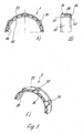
- FIGS. 5A to 5C a part of the two holding means 3 is shown, each formed by a ring segment made of plastic material.
- the holding means 3 have an inner peripheral surface 30 which can be applied to the cylindrical portion 12.
- the inner peripheral surface is widened at the end, with one edge 31 resting against the curvature 11, while the opposite edge 32 rests against the widening 13, so that the retaining means 3 can be received in a form-fitting manner on the socket 1 in the axial direction.
- the holding means 3 also have an outer peripheral surface 33, on which the flange 2 can be pushed with the opening 20.
- the outer peripheral surface 33 has approximately the same diameter as the outer surface of the receptacle 15. Between the inner peripheral surface 30 and the outer peripheral surface 33 hollow chambers 34 are formed, so that the holding means 3 form a spacer for the flange 2 and center them relative to the nozzle 1 ,
- the outer peripheral surface 33 is interrupted at points 35 at which locking lugs 36 are provided.
- the latching lugs 36 are integrally formed on one axial end of the holding means 3 and protrude radially beyond the outer circumferential surface 33, so that the flange 2 can be pushed over the latching lugs 36 so that they then deform radially inwardly and moved back after a release in the radial direction, so that an end edge of the locking lugs 36 secures the flange 2 in the axial direction.
- the two ring segments are inserted for mounting the flange in the receptacle 12 and then the flange 2 is snapped with the opening 20. Thereafter, the flange 2 can no longer be withdrawn in the axial direction and the holding means 3 as ring segments can not be moved in the radial direction to the outside, since this prevents the flange 2.
- the latching lugs 36 would all have to be pressed inwards in order first to remove the flange 2 again and then to remove the holding means 3.
- the holding means 3 are formed by two segments which can be placed around the neck 1.
- the individual segments can be connected to one another via a joint, for example a film hinge formed by a material weakening.
- the holding means does not have to extend around the entire circumference of the neck 1, but it may also be sufficient to elastically latch a retaining means over the neck, wherein the in the FIGS. 5A to 5C segment shown could enclose an angle of for example 230 to 360 ° of the nozzle 1, so that even a centering of the flange 2 is ensured.
- a clamping fixation of the flange 2 can also take place.
- wedge-shaped widening segments between the cylindrical portion 12 and the opening 20 may be provided, which then provide a fixation of the flange 2.
Landscapes
- Engineering & Computer Science (AREA)
- General Engineering & Computer Science (AREA)
- Mechanical Engineering (AREA)
- Quick-Acting Or Multi-Walled Pipe Joints (AREA)
- Flanged Joints, Insulating Joints, And Other Joints (AREA)
Applications Claiming Priority (1)
| Application Number | Priority Date | Filing Date | Title |
|---|---|---|---|
| DE202005001715U DE202005001715U1 (de) | 2005-02-03 | 2005-02-03 | Flanschverbindung für Leitungen |
Publications (2)
| Publication Number | Publication Date |
|---|---|
| EP1688655A1 EP1688655A1 (de) | 2006-08-09 |
| EP1688655B1 true EP1688655B1 (de) | 2008-11-12 |
Family
ID=36228562
Family Applications (1)
| Application Number | Title | Priority Date | Filing Date |
|---|---|---|---|
| EP05026821A Active EP1688655B1 (de) | 2005-02-03 | 2005-12-08 | Flanschverbindung für Leitungen |
Country Status (4)
| Country | Link |
|---|---|
| US (1) | US7481462B2 (ja) |
| EP (1) | EP1688655B1 (ja) |
| JP (1) | JP2006214583A (ja) |
| DE (2) | DE202005001715U1 (ja) |
Families Citing this family (23)
| Publication number | Priority date | Publication date | Assignee | Title |
|---|---|---|---|---|
| US8166584B2 (en) | 2000-06-13 | 2012-05-01 | Wcm Industries, Inc. | Overflow assembly for bathtubs and the like |
| US9015876B2 (en) | 2005-08-23 | 2015-04-28 | Wcm Industries, Inc. | Cover and method for covering the flange of a waste water strainer |
| US9015870B2 (en) * | 2005-08-23 | 2015-04-28 | Wcm Industries, Inc. | Means for covering the flange of a waste water strainer |
| US7712797B2 (en) * | 2005-10-07 | 2010-05-11 | Grundfos Pumps Corporation | Universal fluid coupling assembly with interchangeable fitting members |
| US9234337B2 (en) | 2010-10-19 | 2016-01-12 | Wcm Industries, Inc. | Foot-actuated drain stopper |
| US8813272B2 (en) | 2010-10-19 | 2014-08-26 | Wcm Industries, Inc. | Device and method for concealing a flange of a waste water strainer |
| JP5911879B2 (ja) | 2010-11-02 | 2016-04-27 | ブリュッヒャー メタル アクティーゼルスカブ | 管路 |
| EP2683614B1 (en) | 2011-03-07 | 2018-05-02 | Nordson Corporation | Sanitary fitting with parabolic entrance |
| US9068678B2 (en) * | 2011-09-21 | 2015-06-30 | Ips Corporation | Replacement closet flange |
| US10294648B2 (en) | 2013-06-28 | 2019-05-21 | Darrell Gregory Connell | Toilet flange that can be rotated during insertion having a gripping ring and a durable safety seal |
| US10465370B2 (en) * | 2013-10-25 | 2019-11-05 | Maax Bath Inc. | Pipe connector |
| DE102013018159A1 (de) * | 2013-12-05 | 2015-06-11 | Klaus Union Gmbh & Co. Kg | Spalttopf und Verfahren zur Herstellung desselben |
| KR101654238B1 (ko) * | 2015-11-23 | 2016-09-06 | 정우금속공업 주식회사 | 배관 연결장치 및 이의 제조방법 |
| AU201612717S (en) * | 2015-11-23 | 2016-06-07 | Jung Woo Metal Ind Co | Pipe connector |
| US10563385B1 (en) | 2016-05-17 | 2020-02-18 | Wcm Industries, Inc. | Overflow cover interconnection system |
| US10443220B2 (en) | 2016-08-12 | 2019-10-15 | Wcm Industries, Inc. | Device for providing improved drainage |
| US11398719B2 (en) | 2019-04-30 | 2022-07-26 | Eaton Intelligent Power Limited | Press fit condulet devices, assemblies systems and methods for electrical raceway fabrication |
| RU2745175C1 (ru) * | 2019-10-25 | 2021-03-22 | Данфосс А/С | Вкладыш теплообменника |
| JP7327097B2 (ja) * | 2019-11-14 | 2023-08-16 | 住友電装株式会社 | 配線部材 |
| USD1003406S1 (en) | 2020-03-13 | 2023-10-31 | Wcm Industries, Inc. | Cover for a bathtub overflow system |
| US11814832B2 (en) | 2020-03-13 | 2023-11-14 | Wcm Industries, Inc. | Overflow covers and overflow systems for bathtubs |
| US11996683B2 (en) * | 2020-10-19 | 2024-05-28 | Eaton Intelligent Power Limited | Compressible condulet devices, assemblies, systems and methods for electrical raceway fabrication |
| US12015256B2 (en) * | 2020-12-23 | 2024-06-18 | Eaton Intelligent Power Limited | Push-in condulet devices, assemblies, systems and methods for electrical raceway fabrication |
Citations (1)
| Publication number | Priority date | Publication date | Assignee | Title |
|---|---|---|---|---|
| US6494503B1 (en) * | 2000-03-25 | 2002-12-17 | Non Metallic Resources, Inc. | Pipe joint assembly and method for using same |
Family Cites Families (27)
| Publication number | Priority date | Publication date | Assignee | Title |
|---|---|---|---|---|
| DE24273C (de) * | C. ELSE in Cöthen | Rohrverbindung | ||
| US1291578A (en) * | 1918-02-28 | 1919-01-14 | James Mcphail | Steam-boiler. |
| US1358714A (en) * | 1920-07-30 | 1920-11-16 | Douglas George | Water-closet floor connection |
| US1514065A (en) * | 1921-03-08 | 1924-11-04 | Michael O Leary | Sanitary closet connection |
| US2290333A (en) * | 1940-12-17 | 1942-07-21 | American Hard Rubber Co | Flanged metal pipe with plastic lining |
| US2912712A (en) * | 1955-10-31 | 1959-11-17 | William S Shamban | One-piece grommet |
| US3222093A (en) * | 1963-04-11 | 1965-12-07 | Carrier Corp | Fastening apparatus |
| US3243206A (en) * | 1963-12-30 | 1966-03-29 | Thomas & Betts Co Inc | Fitting for connecting pliable conduit to apertured member |
| FR1574996A (ja) * | 1968-07-18 | 1969-07-18 | ||
| GB1317758A (en) * | 1970-07-30 | 1973-05-23 | Victaulic Co Of America | Pipe couplings |
| DE7426315U (de) * | 1974-08-02 | 1975-05-28 | Berghoefer H | Elastisches Rohrverbindungsstück |
| JPS5313630A (en) * | 1976-07-26 | 1978-02-07 | Masayasu Ejima | Production method of hard gravel from soft stoneemixed brittle raw pit gravel |
| JPS5492422A (en) * | 1977-12-29 | 1979-07-21 | Mitsubishi Pencil Co | Pen point made of synthetic resin |
| JPS5759750Y2 (ja) * | 1978-10-30 | 1982-12-20 | ||
| US4564928A (en) * | 1982-09-30 | 1986-01-14 | New York Institute Of Technology | Graphical data apparatus |
| JPH0432554Y2 (ja) * | 1986-09-05 | 1992-08-05 | ||
| US4770447A (en) * | 1986-09-25 | 1988-09-13 | Usui Kokusai Sangyo Kabushiki Kaisha | Apparatus for joining a thin metal pipe to a flange joint |
| FR2649469B1 (fr) * | 1989-07-04 | 1991-10-25 | Wimetal Sa | Tube, notamment pour ligne d'echappement pour vehicule automobile et comportant au moins un organe de liaison |
| JPH05280677A (ja) * | 1992-04-06 | 1993-10-26 | Sekisui Chem Co Ltd | ライニング管のフランジ構造 |
| JP3056326B2 (ja) * | 1992-04-06 | 2000-06-26 | 積水化学工業株式会社 | ライニング管のフランジ構造 |
| JPH0875062A (ja) * | 1994-09-09 | 1996-03-19 | Hitachi Ltd | サニタリーヘルール継手の回り止め構造 |
| JPH09222189A (ja) * | 1996-02-16 | 1997-08-26 | Silver Ee L Kk | アルミニウム被覆樹脂管のフランジ連結具 |
| AUPO158196A0 (en) | 1996-08-13 | 1996-09-05 | Shawley Investments Pty Ltd | Pipe coupling flange assembly |
| JP3149390B2 (ja) * | 1997-07-09 | 2001-03-26 | 株式会社大創 | 管継手 |
| DE29721760U1 (de) | 1997-12-10 | 1998-01-29 | Franz Viegener II GmbH & Co. KG, 57439 Attendorn | Unlösbare Preßverbindung zwischen einem Fitting und einem Metallrohrende |
| JP2000018957A (ja) * | 1998-06-30 | 2000-01-21 | Nissan Motor Co Ltd | ナビゲーション装置 |
| US6634034B2 (en) * | 2000-11-21 | 2003-10-21 | Jeffrey D. Rendell | Adjustable toilet flange assembly |
-
2005
- 2005-02-03 DE DE202005001715U patent/DE202005001715U1/de not_active Expired - Lifetime
- 2005-12-08 EP EP05026821A patent/EP1688655B1/de active Active
- 2005-12-08 DE DE502005005946T patent/DE502005005946D1/de active Active
-
2006
- 2006-01-19 US US11/335,287 patent/US7481462B2/en active Active
- 2006-01-31 JP JP2006022261A patent/JP2006214583A/ja active Pending
Patent Citations (1)
| Publication number | Priority date | Publication date | Assignee | Title |
|---|---|---|---|---|
| US6494503B1 (en) * | 2000-03-25 | 2002-12-17 | Non Metallic Resources, Inc. | Pipe joint assembly and method for using same |
Also Published As
| Publication number | Publication date |
|---|---|
| EP1688655A1 (de) | 2006-08-09 |
| JP2006214583A (ja) | 2006-08-17 |
| US20060170208A1 (en) | 2006-08-03 |
| DE202005001715U1 (de) | 2006-06-14 |
| US7481462B2 (en) | 2009-01-27 |
| DE502005005946D1 (de) | 2008-12-24 |
Similar Documents
| Publication | Publication Date | Title |
|---|---|---|
| EP1688655B1 (de) | Flanschverbindung für Leitungen | |
| DE19846475A1 (de) | Flachdichtungsring | |
| EP2703707B1 (de) | System zum Herstellen einer dichten Rohrverbindung | |
| EP0054574A1 (de) | Flansch | |
| DE3317061A1 (de) | Flanschverbindungsanordnung | |
| EP0848200B1 (de) | Rohrpresskupplung | |
| EP1564473B1 (de) | Steckfitting mit einem Klemmring | |
| DE3838935A1 (de) | Kupplungsstueck | |
| EP2904301B1 (de) | Halteriegel für eine muffenrohrverbindung | |
| EP2322831A1 (de) | Rohrpresskupplung, insbesondere zur Verpressung von Mehrschichtrohren, sowie Verfahren zum Anbringen einer Rohrpresskupplung | |
| DE60205641T2 (de) | Zur verbindung zweier röhrenförmiger elemente verwendete kupplung und montageverfahren dafür | |
| EP2133613B1 (de) | Anschlussverbindung, insbesondere zum Verbinden von Solarkollektoren | |
| DE19702289A1 (de) | Anordnung zur Verbindung von Rohren oder Schläuchen mit Armaturen oder Fittings | |
| DE202020103581U1 (de) | Flanschverbindungsanordnung für eine Rohrleitung | |
| EP2019246A2 (de) | Anordnung zur Befestigung einer Leitung mit einem profilierten Aussendurchmesser und Montageverfahren | |
| EP2193303B1 (de) | Pressfitting für ein rohr, insbesondere kunststoffrohr oder kunststoff-metall-verbundrohr | |
| EP1306601B1 (de) | Pressfitting für den Anschluss mindestens eines Rohres | |
| EP2183518B1 (de) | Schutzkappe für einen steckfitting | |
| DE3833535C2 (de) | Rohrkupplung | |
| WO2009062463A1 (de) | Rohrleitung | |
| DE10234015B4 (de) | Flanschverbindung | |
| DE10331381A1 (de) | Pressverbindung und Stützhülse für eine Pressverbindung | |
| EP1912010A1 (de) | Fitting für ein Rohr | |
| EP0657671A1 (de) | Fixpunktbefestigung einer Rohrleitung an einer Gebäudewand | |
| DE202015100630U1 (de) | Schlauchschelle zum Sichern eines Wellschlauchs |
Legal Events
| Date | Code | Title | Description |
|---|---|---|---|
| PUAI | Public reference made under article 153(3) epc to a published international application that has entered the european phase |
Free format text: ORIGINAL CODE: 0009012 |
|
| 17P | Request for examination filed |
Effective date: 20060624 |
|
| AK | Designated contracting states |
Kind code of ref document: A1 Designated state(s): AT BE BG CH CY CZ DE DK EE ES FI FR GB GR HU IE IS IT LI LT LU LV MC NL PL PT RO SE SI SK TR |
|
| AX | Request for extension of the european patent |
Extension state: AL BA HR MK YU |
|
| 17Q | First examination report despatched |
Effective date: 20060925 |
|
| AKX | Designation fees paid |
Designated state(s): CH DE FR IT LI |
|
| GRAP | Despatch of communication of intention to grant a patent |
Free format text: ORIGINAL CODE: EPIDOSNIGR1 |
|
| GRAS | Grant fee paid |
Free format text: ORIGINAL CODE: EPIDOSNIGR3 |
|
| GRAA | (expected) grant |
Free format text: ORIGINAL CODE: 0009210 |
|
| AK | Designated contracting states |
Kind code of ref document: B1 Designated state(s): CH DE FR IT LI |
|
| REG | Reference to a national code |
Ref country code: CH Ref legal event code: NV Representative=s name: TROESCH SCHEIDEGGER WERNER AG Ref country code: CH Ref legal event code: EP |
|
| REF | Corresponds to: |
Ref document number: 502005005946 Country of ref document: DE Date of ref document: 20081224 Kind code of ref document: P |
|
| PLBE | No opposition filed within time limit |
Free format text: ORIGINAL CODE: 0009261 |
|
| STAA | Information on the status of an ep patent application or granted ep patent |
Free format text: STATUS: NO OPPOSITION FILED WITHIN TIME LIMIT |
|
| 26N | No opposition filed |
Effective date: 20090813 |
|
| REG | Reference to a national code |
Ref country code: FR Ref legal event code: PLFP Year of fee payment: 11 |
|
| REG | Reference to a national code |
Ref country code: FR Ref legal event code: PLFP Year of fee payment: 12 |
|
| REG | Reference to a national code |
Ref country code: DE Ref legal event code: R082 Ref document number: 502005005946 Country of ref document: DE Representative=s name: COHAUSZ & FLORACK PATENT- UND RECHTSANWAELTE P, DE Ref country code: DE Ref legal event code: R081 Ref document number: 502005005946 Country of ref document: DE Owner name: VIEGA TECHNOLOGY GMBH & CO. KG, DE Free format text: FORMER OWNER: VIEGA GMBH & CO. KG, 57439 ATTENDORN, DE |
|
| REG | Reference to a national code |
Ref country code: FR Ref legal event code: TP Owner name: VIEGA TECHNOLOGY GMBH & CO. KG, DE Effective date: 20171013 |
|
| REG | Reference to a national code |
Ref country code: FR Ref legal event code: PLFP Year of fee payment: 13 |
|
| REG | Reference to a national code |
Ref country code: CH Ref legal event code: PUE Owner name: VIEGA TECHNOLOGY GMBH AND CO. KG, DE Free format text: FORMER OWNER: VIEGA GMBH AND CO. KG, DE |
|
| PGFP | Annual fee paid to national office [announced via postgrant information from national office to epo] |
Ref country code: FR Payment date: 20211214 Year of fee payment: 17 |
|
| PGFP | Annual fee paid to national office [announced via postgrant information from national office to epo] |
Ref country code: IT Payment date: 20221220 Year of fee payment: 18 |
|
| PG25 | Lapsed in a contracting state [announced via postgrant information from national office to epo] |
Ref country code: FR Free format text: LAPSE BECAUSE OF NON-PAYMENT OF DUE FEES Effective date: 20221231 |
|
| PGFP | Annual fee paid to national office [announced via postgrant information from national office to epo] |
Ref country code: DE Payment date: 20231220 Year of fee payment: 19 |
|
| PGFP | Annual fee paid to national office [announced via postgrant information from national office to epo] |
Ref country code: CH Payment date: 20240101 Year of fee payment: 19 |