EP1686779A1 - Groupe téléphonique sans fil - Google Patents
Groupe téléphonique sans fil Download PDFInfo
- Publication number
- EP1686779A1 EP1686779A1 EP06250450A EP06250450A EP1686779A1 EP 1686779 A1 EP1686779 A1 EP 1686779A1 EP 06250450 A EP06250450 A EP 06250450A EP 06250450 A EP06250450 A EP 06250450A EP 1686779 A1 EP1686779 A1 EP 1686779A1
- Authority
- EP
- European Patent Office
- Prior art keywords
- communication
- main device
- signal strength
- unit
- radio
- Prior art date
- Legal status (The legal status is an assumption and is not a legal conclusion. Google has not performed a legal analysis and makes no representation as to the accuracy of the status listed.)
- Granted
Links
- 238000004891 communication Methods 0.000 claims abstract description 162
- 238000001514 detection method Methods 0.000 claims abstract description 15
- 230000008859 change Effects 0.000 claims description 10
- 230000005540 biological transmission Effects 0.000 claims description 7
- 238000000034 method Methods 0.000 description 37
- 230000008569 process Effects 0.000 description 22
- 238000010586 diagram Methods 0.000 description 5
- 230000004044 response Effects 0.000 description 4
- 239000000284 extract Substances 0.000 description 2
- 239000004973 liquid crystal related substance Substances 0.000 description 2
- 230000000881 depressing effect Effects 0.000 description 1
- 230000000694 effects Effects 0.000 description 1
- 238000012986 modification Methods 0.000 description 1
- 230000004048 modification Effects 0.000 description 1
Images


Classifications
-
- H—ELECTRICITY
- H04—ELECTRIC COMMUNICATION TECHNIQUE
- H04M—TELEPHONIC COMMUNICATION
- H04M1/00—Substation equipment, e.g. for use by subscribers
- H04M1/72—Mobile telephones; Cordless telephones, i.e. devices for establishing wireless links to base stations without route selection
- H04M1/725—Cordless telephones
- H04M1/72502—Cordless telephones with one base station connected to a single line
- H04M1/72516—Cordless telephones with one base station connected to a single line with means for out-of-range alerting
-
- H—ELECTRICITY
- H04—ELECTRIC COMMUNICATION TECHNIQUE
- H04B—TRANSMISSION
- H04B17/00—Monitoring; Testing
- H04B17/30—Monitoring; Testing of propagation channels
- H04B17/309—Measuring or estimating channel quality parameters
- H04B17/318—Received signal strength
-
- H—ELECTRICITY
- H04—ELECTRIC COMMUNICATION TECHNIQUE
- H04M—TELEPHONIC COMMUNICATION
- H04M1/00—Substation equipment, e.g. for use by subscribers
- H04M1/72—Mobile telephones; Cordless telephones, i.e. devices for establishing wireless links to base stations without route selection
- H04M1/724—User interfaces specially adapted for cordless or mobile telephones
-
- H—ELECTRICITY
- H04—ELECTRIC COMMUNICATION TECHNIQUE
- H04M—TELEPHONIC COMMUNICATION
- H04M1/00—Substation equipment, e.g. for use by subscribers
- H04M1/72—Mobile telephones; Cordless telephones, i.e. devices for establishing wireless links to base stations without route selection
- H04M1/725—Cordless telephones
- H04M1/72502—Cordless telephones with one base station connected to a single line
Definitions
- aspects of the present invention relate to a cordless telephone set including a main device connected to a telephone line network and a mobile device connected via a radio circuit to the main device, and the mobile device for use with the telephone set.
- cordless telephone set including a main device connected to the telephone line network, and a mobile device connected via the radio circuit to the main device is well known.
- This cordless telephone set is well known in which when the user is talking employing the mobile device (i.e., the mobile device is connected via the main device to the telephone line network), the mobile device measures the signal strength of radio signal transmitted from the main device, and displays the measured result on the display of the mobile device (e.g., refer to JP-B-3-32254).
- the user can know the communication status between the main device and the mobile device by seeing the display during the telephone conversation.
- the signal strength measured in the mobile device is varied depending on the position at which the user has the mobile device.
- the signal strength displayed on the display is varied, so that the user cannot know the communication status between the main device and the mobile device during the telephone conversation.
- This invention provides a cordless telephone set and its mobile device in which the user can be informed of the communication status close to the talking condition.
- an additional device for a cordless telephone set including: a communication unit that makes radio communication with a main device; a communication control unit that decides a radio channel for communication available to transmit and receive a signal to or from the main device, when a calling command is inputted or a call signal transmitted by radio from the main device is received by the communication unit, and then transmits or receives the signal by enabling the communication unit to make the radio communication with the main device, employing the decided radio channel for communication; a display unit that displays information; a signal strength detection unit that periodically detects a signal strength of a radio signal received from the main device by the communication unit, when the communication unit makes the radio communication with the main device under a control of the communication control unit; a signal strength estimation unit that estimates a current signal strength based on a plurality of signal strengths acquired before, by sequentially acquiring the signal strength detected by the signal strength detection unit; and a display control unit that displays a communication status with the main device on the display unit, based on the
- the signal strength detection unit periodically detects the signal strength of radio signal received from the main device by the communication unit, when the communication unit makes the radio communication via the radio channel for communication with the main device under the control of the communication control unit, and the signal strength estimation unit estimates the current signal strength of the radio signal from the main device, based on plural signal strengths acquired in the past, by sequentially acquiring the signal strength detected by the signal strength detection unit.
- the display control unit displays a communication status with the main device on the display unit, based on the signal strength estimated by the signal strength estimation unit.
- the communication unit makes the radio communication via the radio channel for communication with the main device under the control of the communication control unit (i.e., when the user is talking employing the additional device)
- the communication status is not rapidly changed, even when the user moves the additional device from the ear to confirm the communication status displayed on the display unit.
- the user can know the communication status similar to that of the talking condition.
- Fig. 1 is a perspective view of a cordless telephone set 1 according to an aspect of the invention.
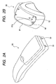
- Fig. 2A is a perspective view showing the rear face of a mobile device 50 and
- Fig. 2B is a perspective view of a charging stand 80.
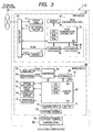
- Fig. 3 is a block diagram showing the electrical configuration of the cordless telephone set 1.
- the cordless telephone set 1 has a function (telephone call function) of talking over the telephone via a telephone linenetwork 100 (see Fig. 3) and a function (facsimile function) of transmitting or receiving the image data via the telephone line network 100, and, as shown in Fig. 1, includes a main device 10 connected to the telephone line network 100, a mobile device 50 connected via a radio circuit to the main device 10, and a charging stand 80, connected to an external power source, not shown, for charging the mobile device 50 at a predetermined voltage, the mobile device 50 being laid detachably.
- the components regarding the facsimile function are not directly related with the invention, and not described here.
- the main device 10 has a handset 12 that is a transmitter-receiver on the side portion of a main device main case 11, in which the handset is detached from a main body of the main device 10, when used.
- a display panel 13 for displaying the information relevant to various kinds of functions and various kinds of operation buttons 14, including a dial button 14a for inputting the telephone number of the other party and a selection button 14b that is operated for selecting from the menu screen displayed on the display panel 13 are provided on an upper face of the main device main case 11.
- the display panel 13 is a liquid crystal display (LCD) with a back light for illuminating the display screen from the back side.
- LCD liquid crystal display
- the mobile device 50 includes a display panel 53 for displaying the information relevant to various kinds of functions, various kinds of operation buttons 54 including a dial button 54a for inputting the telephone number of the other party, an outside line call button 54b that is operated in starting the outside line call, an off button 54c that is operated in terminating the talking, and a selection button 54d that is operated for selecting from the menu screen displayed on the display panel 53, and a charging terminal 55 (see Fig. 2A) for charging a battery 74 (see Fig. 3) for supplying electric power to the whole of the mobile device 50 from a charging stand 80 on the surface of a mobile device main case 51 having a shape of handset.
- various kinds of operation buttons 54 including a dial button 54a for inputting the telephone number of the other party, an outside line call button 54b that is operated in starting the outside line call, an off button 54c that is operated in terminating the talking, and a selection button 54d that is operated for selecting from the menu screen displayed on the display panel 53, and a charging terminal 55 (see
- the display panel 53 is a liquid crystal display (LCD) with a back light for illuminating the display screen from the back side.
- LCD liquid crystal display
- the charging stand 80 includes a charging stand main body 81 formed with a laying concave portion 81a on which the mobile device 50 is detachably laid, and a charging terminal 82, provided within the laying concave portion 81a, for making contact with the charging terminal 55 when the mobile device 50 is laid on the laying concave portion 81a, as shown in Fig. 2B.
- the main device 10 includes a control part 20 for controlling the overall operation of the main device 10, a handset 12, a display panel 13, an operation button 14, and a radio communication part 30 for transmitting or receiving by radio a voice signal (corresponding to a talking signal) or a data signal to or from the mobile device 50.
- a control part 20 for controlling the overall operation of the main device 10, a handset 12, a display panel 13, an operation button 14, and a radio communication part 30 for transmitting or receiving by radio a voice signal (corresponding to a talking signal) or a data signal to or from the mobile device 50.
- An output signal from the operation button 14, an output signal (voice or data signal) from the radio communication part 30 and a voice signal from outside of the cordless telephone set 1 are inputted into the control part 20.
- control part 20 establishes a transmission path between transmission destination and transmission source of the voice signal inputted or outputted from outside of the cordless telephone set 1. More specifically, when the handset 12 is removed from the main body of the main device 10, the transmission path is switched to the handset 12, or when the telephone call start operation for starting the telephone call is performed by the mobile device 50, the transmission path is switched to the radio communication part 30.
- control part 20 outputs a data signal or a voice signal for radio communication with the mobile device 50 to the radio communication part 30, and outputs a voice signal from the handset 12 and the radio communication part 30 to the outside of the cordless telephone set 1.
- the radio communication part 30 includes a radio communication control part 32 composed of a CPU, a RAM, a ROM and an A/D converter, an EEPROM 34, a compander36, and an RF module 38 for making the radio communication with the mobile device 50.
- a radio communication control part 32 composed of a CPU, a RAM, a ROM and an A/D converter, an EEPROM 34, a compander36, and an RF module 38 for making the radio communication with the mobile device 50.
- the compander36 acquires a radio signal sent from the mobile device 50 via the RF module 38, and segregates its signal into a voice signal and a data signal, the voice signal being sent to the control part 20, and the data signal being sent to the radio communication control part 32. Also, the compander36 sends the voice signal from the control part 20 or the data signal from the radio communication control part 32 to the RF module 38.
- the RF module 38 is configured to be communicable with the radio communication control part 32, selects a radio channel for use in the radio communication from among a plurality of radio channels having different frequencies in accordance with a command from the radio communication control part 32, and sends an output signal from the compander36 to the mobile device 50, as well as receives the radio signal sent from the mobile device 50, employing the selected radio channel.
- the radio channels that the RF module 38 employs for radio communication are 89 radio channels with a frequency interval between each radio channel being 12.5kHz in a band of 380MHz.
- the radio channels that the mobile device 50 (more particularly the RF module 68) employs for radio communication are 89 radio channels with a frequency interval between each radio channel being 12.5kHz in a band of 280MHz.
- the 46 channel and the 89 channel are employed to transmit or receive the data signal alone, and any one of the remaining 1 channel to 45 channel and 47 channel to 88 channel is employed to transmit or receive the voice signal.
- the 46 and 89 channels are called a control channel and the 1 to 45 and 47 to 88 channels are called a communication channel to distinguish the radio channels used between the main device 10 and the mobile device 50.
- the RF module 38 detects the signal strength of a signal received by radio from the outside, and outputs its detection result to the A/D converter of the radio communication control part 32.
- the A/D converter of the radio communication control part 32 converts the detection result inputted from the RF module 38 into a digital value of 8 bits.
- the data signal outputted from the control part 20 or the compander36 is inputted into the radio communication control part 32.
- the radio communication control part 32 outputs the data signal from the control part 20 to the compander36.
- the radio communication control part 32 selects the available radio channel, based on the signal strength detected by the RF module 38, and transmits its result to the RF module 38, when the main device 10 starts the communication with the mobile device 50.
- the main device 10 starts the radio communication with the mobile device 50, employing the radio channel selected by the radio communication control part 32.
- the mobile device 50 includes a control part 60 for controlling the overall operation of the mobile device 50, a display panel 53, an operation button 54, a receiver 62, a microphone 64, a compander66, an RF module 68 for transmitting or receiving the voice signal or data signal in radio communication with the main device 10 (more particularly the RF module 38), an EEPROM 70, an operation button LED 72 for illuminating the operation button 54 from behind, a battery 74 for supplying electric power to the whole of the mobile device 50, a charging terminal 55 for electrically connecting to the charging terminal 82, and a charging circuit 76 for charging the battery 74 at a power voltage supplied from the charging stand 80 via the charging terminal 55.
- a control part 60 for controlling the overall operation of the mobile device 50
- a display panel 53 for controlling the overall operation of the mobile device 50
- an operation button 54 for a receiver 62, a microphone 64, a compander66, an RF module 68 for transmitting or receiving the voice signal or data signal in radio communication with the main device 10
- the compander66 acquires a radio signal sent from the main device 10 via the RF module 68, and segments its signal into a voice signal and a data signal, the voice signal being sent to the receiver 62, and the data signal being sent to the control part 60. Also, the compander66 sends the voice signal from the microphone 64 or the data signal from the control part 60 to the RF module 68.
- the RF module 68 is configured to be communicable with the control part 60, selects a radio channel for use in the radio communication from among 89 radio channels in accordance with a command from the control part 60, and sends an output signal from the compander66 to the main device 10, as well as receives the radio signal sent from the main device 10, employing the selected radio channel.
- the RF module 68 detects the signal strength of a signal received by radio from the outside, and outputs its detection result to the A/D converter contained in the control part 60.
- the A/D converter of the control part 60 converts the detection result inputted from the RF module 68 into a digital value of 8 bits (hereinafter referred to as an RSSI value).
- the control part 60 includes a CPU, a RAM, a ROM and an A/D converter. An output signal from the operation button 54 or a data signal from the compander66 is inputted into the control part 60.
- control part 60 outputs the data signal for radio communication with the main device 10 to the compander66.
- control part 60 is configured to be communicable with the RF module 68, and selects the available radio channel, based on the signal strength detected by the RF module 68, as well as transmits its result to the RF module 68, when the mobile device 50 starts the communication with the main device 10.
- the mobile device 50 starts the radio communication with the main device 10, employing the radio channel selected by the control part 60.
- control part 60 causes the RF module 68 to periodically acquire the signal strength of radio signal transmitted from the main device 10 via the communication channel, and calculates the average value of five signal strengths (i.e., RSSI value) acquired in the past, when the mobile device 50 is making the radio communication with the main device 10 via the communication channel.
- RSSI value the average value of five signal strengths
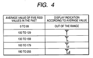
- the control part 60 compares the calculated average value with a plurality of thresholds stored in the ROM, digitizes the average value at stages, generates a typical graphic, based on the digitized result, and displays the generated graphic as a communication status with the main device 10 on the display panel 53.
- a graphic generation table is stored in the ROM of the control part 60.
- the values of 0 to 255 are divided into five stages in terms of the plurality of thresholds, and the figure generated by the control part 60 is associated with each stage, as shown in Fig. 4.
- the graphic generation table shows the graphics corresponding to the communication status that is better as the threshold is higher (downward in Fig. 4), such that the lowest level (0 to 99) corresponds to a graphic indicating the state where the mobile device 50 is incommunicable with the main device 10, the secondly lowest level (100 to 129) corresponds to a graphic indicating the state where the communication status of the main device 10 is worst, and so on.
- the state where the communication status is worst is the state where the main device 10 is communicable with the mobile device 50, but the communication status is worst.
- the control part 60 calculates the average value of five RSSI values acquired in the past from the RF module 68, and extracts the graphic corresponding to the calculated average value by referring to the graphic generation table.
- the control part 60 extracts the graphic from the graphic generation table, and displays the graphic on the display panel 53.
- the charging stand 80 has the charging terminal 82 that is supplied with electric power from a required external power source to generate a predetermined power voltage, and supply electric power to the mobile device 50.
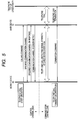
- the mobile device 50 When the user depresses an outside line call button 54b at the mobile device 50 in a no talking state (standby state) to make the telephone call start operation, the mobile device 50 sends a calling command to the main device 10, employing a predetermined control channel (e.g., 46 channel).
- a predetermined control channel e.g., 46 channel
- the main device 10 receiving the calling command selects one communication channel (e.g., 5 channel) for radio communication with the mobile device 50, and sends a specified communication channel' command representing the selected communication channel to the mobile device 50, employing the control channel (46 channel).
- one communication channel e.g., 5 channel
- a specified communication channel' command representing the selected communication channel to the mobile device 50, employing the control channel (46 channel).
- the mobile device 50 receiving the specified communication channel command acquires the signal strength of radio signal in a frequency band of the 5 channel at the RF module 68, and determines whether or not the 5 channel is available, based on the acquired signal strength. In Fig. 5, for the explanation, it is supposed that the 5 channel is determined to be available.
- the mobile device 50 sends a specified communication channel OK response indicating that the 5 channel is available channel to the main device 10, employing the 46 channel.
- the main device 10 receiving the specified communication channel OK response sends a communication channel decision notice indicating that the radio communication is made on the 5 channel from then to the mobile device 50, employing the 46 channel.
- the mobile device 50 receiving the communication channel decision notice is enabled for talking.
- the communicable as used herein means that the communication between the main device 10 and the mobile device 50 is established on the specified communication channel in a state where the mobile device 50 is connected to the telephone line network 100 via the main device 10.
- the user performs a dial operation at the mobile device 50, and the main device 10 sends out a dial signal to the telephone line network 100 to respond to the telephone set of the other side, whereby the outside line telephone call is enabled to the telephone set of the other party.
- the mobile device 50 which becomes in a talking enabled state, acquires the signal strength of radio signal sent via the communication channel (5 channel in this example) from the main device 10 periodically (every 0.5s in this aspect), and displays a graphic extracted from the graphic generation table as the communication status with the main device 10 on the display panel 53, based on the average value of five signal strengths acquired in the past.
- the mobile device 50 sends a telephone call termination command to the main device 10, and stops the display of the graphic.
- the main device 10 receiving the telephone call termination command terminates the outside line telephone call to the telephone set of the other party.
- the main device 10 selects one communication channel (e.g., 5 channel) for radio communication with the mobile device 50, and sends a specified communication channel command indicating the selected communication channel to the mobile device 50, employing a predetermined control channel (e.g., 46 channel).
- one communication channel e.g., 5 channel
- a specified communication channel command indicating the selected communication channel to the mobile device 50, employing a predetermined control channel (e.g., 46 channel).
- the mobile device 50 receiving the specified communication channel command determines whether or not the 5 channel is available, and if the 5 channel is determined to be available, sends a specified communication channel OK response to the main device 10, employing the 46 channel, as described above.
- the main device 10 receiving the specified communication channel OK response sends a communication channel decision notice indicating that the radio communication is made on the 5 channel from then to the mobile device 50, employing the 46 channel.
- the mobile device 50 When the mobile device 50 receives the communication channel decision notice, the mobile device 50 is enabled for talking.
- the mobile device 50 receiving the communication channel decision notice informs the user of an incoming call by ringing. After the user of the mobile device 50 depresses the outside line call button 54b to make the telephone call start operation, the outside line telephone call is enabled to the telephone set of the other party.
- the mobile device 50 displays the communication status with the main device 10 on the display panel 53, as described above.
- the mobile device 50 sends a telephone call termination command to the main device 10, and stops the display of the graphic on the display panel 53.
- the main device 10 receiving the telephone call termination command terminates the outside line telephone call to the telephone set of the other party.
- a communication channel decision process for deciding the communication channel for radio communication with the main device 10 is firstly performed at S110.
- a graphic corresponding to the secondly lowest level is extracted from the graphic generation table and displayed on the display panel 53.
- the radio channel thereafter used is switched from the currently used control channel to the communication channel decided at S110.
- the RSSI value of the currently used communication channel is acquired from the RF module 68, and the acquired RSSI value is stored in the EEPROM 70 for example.
- the RSSI value stored in the EEPROM 70 is read, and the average value of read RSSI values is calculated.
- the graphic corresponding to the average value calculated at S140 is extracted by referring to the graphic generation table stored in the ROM.
- the graphic extracted at S150 is outputted to the display panel 53, and displayed on the display panel 53.
- the graphic corresponding to the highest level (180 to 255) in Fig. 4 is displayed in a left lower region on the display panel 53, as shown in Fig. 8.
- the current time and the operation state of the mobile device 50 are displayed, besides the communication status with the main device 10 displayed at S160.
- the average value of RSSI values only stored in the EEPROM 70 is calculated at S140.
- the mobile device 50 of the first aspect periodically detects the signal strength of radio signal sent via the communication channel, when the user talks employing the mobile device 50 (the mobile device 50 makes the radio communication with the main device 10 via the communication channel), and sequentially acquires the detected signal strength.
- the mobile device 50 then generates a typical graphic, based on the average value of five signal strengths (RSSI values) acquired in the past, and displays the graphic as the communication status with the main device 10 on the display panel 53.
- RSSI values signal strengths
- the user when the user talks employing the mobile device 50, the user can know the communication status similar to that of the talking condition, because the communication status is not rapidly changed, even if the user moves the mobile device 50 from the ear to confirm the communication status displayed on the display panel 53.
- the mobile device 50 displays an indication that the communication status with the main device 10 is worst on the display panel 53 since there is a calling command or an incoming call till the radio communication with the main device 10 is made employing the communication channel, whereby the user can judge that the communicable state is established.
- the cordless telephone set 1 of the first aspect since the current signal strength is obtained based on the average value of five RSSI values in the past, the current signal strength can be simply obtained without being affected by disturbance and derived.
- the cordless telephone set 1 since the average value of five RSSI values in the past are compared with plural thresholds in the graphic generation table, and the graphic corresponding to its average value is displayed on the display panel 53, the user only takes a glance at the display panel 53 to confirm the communication status with the main device 10.
- the RF module 68 functions a as communication unit and a signal strength detection unit
- the flowchart of Fig. 7 functions as a communication control unit.
- the specified communication channel command sent from the main device 10 functions as the call signal
- the control channel functions as the control radio channel
- the communication channel functions as the communication radio channel.
- the display panel 53 functions as a display unit
- the processing at S130 and S140 functions as a signal strength estimation unit
- the processing at S110, S150 and S160 functions as a display control unit.
- a cordless telephone set 2 in contrast to the cordless telephone set 1 of the first aspect, the main device 10 detects the signal strength of radio signal from the mobile device 50, and sends its detection result to the mobile device 50, while the mobile device 50 updates the graphic generation table, based on the detection result received from the main device 10, and displays the communication status with the main device 10 on the display panel 53.
- Fig. 9 is an explanatory view for explaining the graphic generation table after change, Fig.
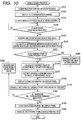
- Fig. 10 is a flowchart showing a process that is performed in the control part 60 when there is an incoming call or the telephone call start operation is performed at the mobile device 50 of the second aspect
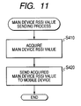
- Fig. 11 is a flowchart showing a process that is performed in the radio communication control part 32 of the main device 10 according to the second aspect
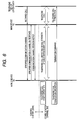
- Fig. 12 is a sequence chart showing the operation that is performed between the main device 10 and the mobile device 50 when the user makes a call from the mobile device 50 according to the second aspect.
- the mobile device 50 according to the second aspect is different in the following two points from the mobile device 50 according to the first aspect.
- the graphic generation table after change as shown in Fig. 9 is stored in the ROM of the control part 60. More specifically, the threshold for each level in the graphic generation table after change is set higher than the threshold for each level in the graphic generation table corresponding to it, as shown in Fig. 9.
- the control part 60 performs a process of Fig. 10, instead of the process of Fig. 7.
- the same steps are given the same step numbers as in the process of Fig. 7, and not described in detail.
- control part 60 performs the process of Fig. 9, and ends the steps S110 and S120, and the procedure goes to S310.
- a command for sending the signal strength detected by the main device 10 in receiving the radio signal from the mobile device 50 from the main device 10 to the mobile device 50 (hereinafter referred to as a main device RSSI value sending command) is outputted to a compander 66.
- a main device RSSI value sending command the signal strength (8-bit digit value) acquired by the main device 10 is called a main device RSSI value and the RSSI value acquired by the mobile device 50 is called a mobile device RSSI value.
- step S310 the mobile device 50 sends a main device RSSI sending command via the communication channel from the RF module 68.
- the procedure waits till the main device RSSI value is received from the main device 10, and when the main device RSSI value is' received, the received main device RSSI value is stored in the RAM for example.
- the mobile device RSSI value in receiving the main device RSSI value is acquired, and stored in the EEPROM 70.
- the threshold used for this determination is set to 30, but may be appropriately set to other value.
- step S140 the graphic corresponding to the average value calculated at S140 is extracted by referring to the graphic generation table at S370.
- the graphic corresponding to the average value calculated at S140 is extracted by referring to the graphic generation table after change, when step S360 is performed in the process of Fig. 10 this time, or conversely, the graphic corresponding to the average value calculated at S140 is extracted by referring to the graphic generation table, when step S360 is not performed in the process of Fig. 10 this time.
- step S370 the procedure goes from S160 to S170 to S180. If it is determined that the telephone call termination command is not inputted at S180, the procedure goes to S380.
- the mobile device RSSI value is acquired, and stored in the EEPROM 70, and the procedure goes to S140.
- the main device 10 according to the second aspect is different from the main device 10 according to the first aspect in the point that the radio communication control part 32 performs a main device RSSI value sending process of Fig. 11.
- a main device RSSI value sending process is performed in the radio communication control part 32.
- the signal strength of radio signal sent via the communication channel for use with the mobile device 50 is acquired via the RF module 38 at S410.
- the main device RSSI value is sent by radio to the RF module 38 by outputting the acquired signal strength (i.e., main device RSSI value) to the compander36, and the main device RSSI value sending process is ended.
- the mobile device 50 when the telephone call start operation is performed by the user depressing the outside line call button 54b in the standby state, the mobile device 50 becomes in a communicable state by switching the control channel (e.g., 46 channel) into the communication channel (e.g., 5 channel) in accordance with the same procedure as in Fig. 5.
- the control channel e.g., 46 channel
- the communication channel e.g., 5 channel
- the mobile device 50 when it becomes in the communicable state, it sends a main device RSSI value sending command to the main device 10, employing the communication channel (5 channel).
- the main device 10 receiving the main device RSSI value sending command acquires the signal strength of radio signal sent on the 5 channel from the mobile device 50, and sends the acquired signal strength (main device RSSI value) to the mobile device 50 via the 5 channel.
- the mobile device 50 receiving the main device RSSI vale acquired the signal strength of radio signal sent on the 5 channel from the main device 10, and compares the acquired mobile device RSSI value with the main device RSSI value.
- the mobile device 50 displays the graphic by referring to the graphic generation table after change when a difference between the mobile device RSSI value and the main device RSSI value is greater than or equal to 30, or conversely, displays the graphic by referring to the graphic generation table, when the difference between the mobile device RSSI value and the main device RSSI value is not greater than or equal to 30.
- the mobile device 50 sends a telephone call termination command to the main device 10, and stops the display of the graphic.
- the main device 10 receiving the telephone call termination command terminates the outside line telephone call to the telephone set of the other party.
- the mobile device 50 when the cordless telephone set 2 has an call incoming from the outside, the mobile device 50 becomes in a communicable state by switching the control channel (e.g., 46 channel) into the communication channel (e.g., 5 channel) in accordance with the same procedure as in Fig. 5.
- the control channel e.g., 46 channel
- the communication channel e.g., 5 channel
- the mobile device 50 displays the communication status, including the communication status from the mobile device 50 to the main device 10 on the display panel 53, whereby the user is informed of more correct communication status.
- the flowchart of Fig. 10 functions as a communication control unit, steps S310 to S360 function as a threshold change unit, and the main device RSSI value sending process functions as a measured result sending unit.
- cordless telephone sets 1 and 2 of the first and second aspects include a facsimile function, they may include any other function, as far as it has the function of the telephone set, to achieve the same effect of the above aspects.
- the average value of five mobile device RSSI values in the past is calculated at S140, the average value of plural mobile device RSSI values in the past, or the deviation of plural mobile device RSSI values in the past may be calculated.
- the graphic displayed on the display panel 53 at step S110 is the graphic indicating the state where the communication status with the main device 10 is worst, but may be the graphic (lowest graphic in Fig. 4 or Fig. 9) indicating the state where the communication status with the main device 10 is most excellent.
- the graphic extracted from the graphic generation table is displayed on the display panel 53 at S160, but the average value calculated at S140 may be directly displayed at S160. In this case, step S150 may not be performed.
- step S110 may be configured to perform the processing from S130 to S170.
- step S120 the main device RSSI value sending command is sent once, but it may be sent at a predetermined interval.
Landscapes
- Engineering & Computer Science (AREA)
- Computer Networks & Wireless Communication (AREA)
- Signal Processing (AREA)
- Human Computer Interaction (AREA)
- Quality & Reliability (AREA)
- Physics & Mathematics (AREA)
- Electromagnetism (AREA)
- Mobile Radio Communication Systems (AREA)
- Telephone Function (AREA)
Applications Claiming Priority (1)
| Application Number | Priority Date | Filing Date | Title |
|---|---|---|---|
| JP2005018695A JP3998019B2 (ja) | 2005-01-26 | 2005-01-26 | コードレス電話装置、及び、その装置の子機 |
Publications (2)
| Publication Number | Publication Date |
|---|---|
| EP1686779A1 true EP1686779A1 (fr) | 2006-08-02 |
| EP1686779B1 EP1686779B1 (fr) | 2009-06-24 |
Family
ID=36216797
Family Applications (1)
| Application Number | Title | Priority Date | Filing Date |
|---|---|---|---|
| EP06250450A Not-in-force EP1686779B1 (fr) | 2005-01-26 | 2006-01-26 | Groupe téléphonique sans fil |
Country Status (5)
| Country | Link |
|---|---|
| US (1) | US20060177049A1 (fr) |
| EP (1) | EP1686779B1 (fr) |
| JP (1) | JP3998019B2 (fr) |
| CN (1) | CN100536503C (fr) |
| DE (1) | DE602006007390D1 (fr) |
Cited By (1)
| Publication number | Priority date | Publication date | Assignee | Title |
|---|---|---|---|---|
| JP2018037967A (ja) * | 2016-09-02 | 2018-03-08 | オムロン株式会社 | 無線通信装置、無線通信システム、および無線通信状態確認方法 |
Families Citing this family (7)
| Publication number | Priority date | Publication date | Assignee | Title |
|---|---|---|---|---|
| JP4596027B2 (ja) | 2008-03-25 | 2010-12-08 | ブラザー工業株式会社 | 通信システム |
| JP5261311B2 (ja) * | 2009-07-30 | 2013-08-14 | パナソニック株式会社 | 火災警報システム |
| JP5112458B2 (ja) * | 2010-02-09 | 2013-01-09 | 東芝テック株式会社 | 無線通信端末およびその制御プログラム |
| CN103179256B (zh) * | 2011-12-23 | 2016-03-30 | 东保电子有限公司 | 无绳电话及其通信方法 |
| US9055425B2 (en) * | 2012-09-27 | 2015-06-09 | Nokia Technologies Oy | Method and apparatus for enhancing emergency calling with mobile devices |
| CN105592199A (zh) * | 2014-10-20 | 2016-05-18 | 深圳富泰宏精密工业有限公司 | 一种优化手机信号强度指示的系统及方法 |
| CN104540157B (zh) * | 2015-01-09 | 2016-08-24 | 努比亚技术有限公司 | 一种来电信号切换方法、装置及终端 |
Citations (4)
| Publication number | Priority date | Publication date | Assignee | Title |
|---|---|---|---|---|
| EP1111822A2 (fr) * | 1999-12-24 | 2001-06-27 | Lucent Technologies Inc. | Indicateur de qualité pour canal sans fils |
| US20020055372A1 (en) * | 2000-10-12 | 2002-05-09 | Nec Corporation | Portable communication terminal with image transmission function |
| US20020193077A1 (en) * | 1995-06-13 | 2002-12-19 | Shigeki Sakurai | Radio communicating apparatus |
| WO2004107607A1 (fr) * | 2003-05-27 | 2004-12-09 | Sanyo Electric Co., Ltd. | Appareil de reception d'ondes radio |
Family Cites Families (9)
| Publication number | Priority date | Publication date | Assignee | Title |
|---|---|---|---|---|
| JPS623536A (ja) * | 1985-06-29 | 1987-01-09 | Oki Electric Ind Co Ltd | 移動体データ通信の良否判定装置 |
| SE467332B (sv) * | 1990-06-21 | 1992-06-29 | Ericsson Telefon Ab L M | Foerfarande foer effektreglering i ett digitalt mobiltelefonisystem |
| WO1995019084A1 (fr) * | 1994-01-05 | 1995-07-13 | Thomson Consumer Electronics, Inc. | Systeme de selection d'une voie libre pour un telephone sans fil |
| US5539803A (en) * | 1994-09-09 | 1996-07-23 | At&T Corp. | Wireless test mode for a cordless telephone |
| US6021314A (en) * | 1997-05-22 | 2000-02-01 | Advanced Micro Devices, Inc. | Free channel selector for selecting an optimal channel |
| US6269257B1 (en) * | 1999-01-21 | 2001-07-31 | Agere Systems Guardian Corp. | Adaptive paging signal in cordless telephone |
| JP2001223600A (ja) * | 2000-02-08 | 2001-08-17 | Nec Saitama Ltd | 無線受信機およびその受信レベル表示方法 |
| US6934315B2 (en) * | 2000-05-17 | 2005-08-23 | Matsushita Electric Industrial Co., Ltd. | Cordless telephone and method for selecting communication channel thereof |
| US7133686B2 (en) * | 2003-01-08 | 2006-11-07 | Vtech Telecommunication Limited | System and method for identifying interferes in a communication spectrum |
-
2005
- 2005-01-26 JP JP2005018695A patent/JP3998019B2/ja active Active
-
2006
- 2006-01-26 EP EP06250450A patent/EP1686779B1/fr not_active Not-in-force
- 2006-01-26 US US11/339,662 patent/US20060177049A1/en not_active Abandoned
- 2006-01-26 CN CNB2006100029683A patent/CN100536503C/zh active Active
- 2006-01-26 DE DE602006007390T patent/DE602006007390D1/de active Active
Patent Citations (4)
| Publication number | Priority date | Publication date | Assignee | Title |
|---|---|---|---|---|
| US20020193077A1 (en) * | 1995-06-13 | 2002-12-19 | Shigeki Sakurai | Radio communicating apparatus |
| EP1111822A2 (fr) * | 1999-12-24 | 2001-06-27 | Lucent Technologies Inc. | Indicateur de qualité pour canal sans fils |
| US20020055372A1 (en) * | 2000-10-12 | 2002-05-09 | Nec Corporation | Portable communication terminal with image transmission function |
| WO2004107607A1 (fr) * | 2003-05-27 | 2004-12-09 | Sanyo Electric Co., Ltd. | Appareil de reception d'ondes radio |
Cited By (1)
| Publication number | Priority date | Publication date | Assignee | Title |
|---|---|---|---|---|
| JP2018037967A (ja) * | 2016-09-02 | 2018-03-08 | オムロン株式会社 | 無線通信装置、無線通信システム、および無線通信状態確認方法 |
Also Published As
| Publication number | Publication date |
|---|---|
| EP1686779B1 (fr) | 2009-06-24 |
| DE602006007390D1 (de) | 2009-08-06 |
| US20060177049A1 (en) | 2006-08-10 |
| CN100536503C (zh) | 2009-09-02 |
| CN1822614A (zh) | 2006-08-23 |
| JP3998019B2 (ja) | 2007-10-24 |
| JP2006211147A (ja) | 2006-08-10 |
Similar Documents
| Publication | Publication Date | Title |
|---|---|---|
| JP4207005B2 (ja) | コードレス装置 | |
| EP1686779B1 (fr) | Groupe téléphonique sans fil | |
| US7567656B2 (en) | Telephone communication apparatus | |
| US5602900A (en) | Radio Telecommunication apparatus | |
| US6366784B1 (en) | Mobile phone extension set | |
| US6547620B1 (en) | Communication apparatus, memory medium and method | |
| US7746995B2 (en) | Telephone control system | |
| EP0438137B1 (fr) | Dispositif de radio-télécommunication | |
| US7292869B2 (en) | Telephone equipment including a line holding system, an extension communication detecting system, and a notification system | |
| JP2007281624A (ja) | 電話装置およびその回線切断方法 | |
| KR100497986B1 (ko) | 데이터 가변변조전송기능이 구비된 무선전화시스템 | |
| JP4205647B2 (ja) | コードレス電話機における制御チャネル切り替え方法及びコードレス電話システム及びコードレス電話機 | |
| KR200286903Y1 (ko) | 이동단말기의 다기능 충전기 | |
| JPH0918371A (ja) | 移動通信端末装置 | |
| JP2014143580A (ja) | 無線通信装置および送信電力制御方法 | |
| JP2006081027A (ja) | コードレス式ボタン電話装置 | |
| KR20030063501A (ko) | 이동단말기의 다기능 충전기 및 이의 구동방법 | |
| JPH07221819A (ja) | 電話装置 | |
| JP3135458B2 (ja) | 無線通信装置 | |
| JP2007088869A (ja) | ドアホンと接続可能なコードレス電話装置及びドアホンシステム | |
| KR20030091099A (ko) | 이동단말기의 다기능 충전기 및 이의 구동방법 | |
| JPH03220927A (ja) | 無線電話装置 | |
| JPH05276104A (ja) | 無線電話装置 | |
| JPH1051856A (ja) | 携帯電話機の圏外移動通知システム | |
| KR20030055561A (ko) | 가변 통화회로기능을 구비한 더불유엘엘 단말기 |
Legal Events
| Date | Code | Title | Description |
|---|---|---|---|
| PUAI | Public reference made under article 153(3) epc to a published international application that has entered the european phase |
Free format text: ORIGINAL CODE: 0009012 |
|
| AK | Designated contracting states |
Kind code of ref document: A1 Designated state(s): AT BE BG CH CY CZ DE DK EE ES FI FR GB GR HU IE IS IT LI LT LU LV MC NL PL PT RO SE SI SK TR |
|
| AX | Request for extension of the european patent |
Extension state: AL BA HR MK YU |
|
| 17P | Request for examination filed |
Effective date: 20061130 |
|
| AKX | Designation fees paid |
Designated state(s): DE FR GB |
|
| GRAP | Despatch of communication of intention to grant a patent |
Free format text: ORIGINAL CODE: EPIDOSNIGR1 |
|
| GRAS | Grant fee paid |
Free format text: ORIGINAL CODE: EPIDOSNIGR3 |
|
| GRAA | (expected) grant |
Free format text: ORIGINAL CODE: 0009210 |
|
| AK | Designated contracting states |
Kind code of ref document: B1 Designated state(s): DE FR GB |
|
| REG | Reference to a national code |
Ref country code: GB Ref legal event code: FG4D |
|
| REF | Corresponds to: |
Ref document number: 602006007390 Country of ref document: DE Date of ref document: 20090806 Kind code of ref document: P |
|
| PLBE | No opposition filed within time limit |
Free format text: ORIGINAL CODE: 0009261 |
|
| STAA | Information on the status of an ep patent application or granted ep patent |
Free format text: STATUS: NO OPPOSITION FILED WITHIN TIME LIMIT |
|
| 26N | No opposition filed |
Effective date: 20100325 |
|
| REG | Reference to a national code |
Ref country code: FR Ref legal event code: PLFP Year of fee payment: 11 |
|
| REG | Reference to a national code |
Ref country code: FR Ref legal event code: PLFP Year of fee payment: 12 |
|
| REG | Reference to a national code |
Ref country code: FR Ref legal event code: PLFP Year of fee payment: 13 |
|
| PGFP | Annual fee paid to national office [announced via postgrant information from national office to epo] |
Ref country code: FR Payment date: 20171211 Year of fee payment: 13 |
|
| PGFP | Annual fee paid to national office [announced via postgrant information from national office to epo] |
Ref country code: GB Payment date: 20180124 Year of fee payment: 13 |
|
| GBPC | Gb: european patent ceased through non-payment of renewal fee |
Effective date: 20190126 |
|
| PG25 | Lapsed in a contracting state [announced via postgrant information from national office to epo] |
Ref country code: FR Free format text: LAPSE BECAUSE OF NON-PAYMENT OF DUE FEES Effective date: 20190131 |
|
| PG25 | Lapsed in a contracting state [announced via postgrant information from national office to epo] |
Ref country code: GB Free format text: LAPSE BECAUSE OF NON-PAYMENT OF DUE FEES Effective date: 20190126 |
|
| PGFP | Annual fee paid to national office [announced via postgrant information from national office to epo] |
Ref country code: DE Payment date: 20221130 Year of fee payment: 18 |
|
| REG | Reference to a national code |
Ref country code: DE Ref legal event code: R119 Ref document number: 602006007390 Country of ref document: DE |