EP1684002B1 - Leuchteinheit mit Lichtteiler - Google Patents
Leuchteinheit mit Lichtteiler Download PDFInfo
- Publication number
- EP1684002B1 EP1684002B1 EP06000553A EP06000553A EP1684002B1 EP 1684002 B1 EP1684002 B1 EP 1684002B1 EP 06000553 A EP06000553 A EP 06000553A EP 06000553 A EP06000553 A EP 06000553A EP 1684002 B1 EP1684002 B1 EP 1684002B1
- Authority
- EP
- European Patent Office
- Prior art keywords
- light
- lamp unit
- unit according
- light source
- deflection
- Prior art date
- Legal status (The legal status is an assumption and is not a legal conclusion. Google has not performed a legal analysis and makes no representation as to the accuracy of the status listed.)
- Active
Links
Images


Classifications
-
- G—PHYSICS
- G02—OPTICS
- G02B—OPTICAL ELEMENTS, SYSTEMS OR APPARATUS
- G02B6/00—Light guides; Structural details of arrangements comprising light guides and other optical elements, e.g. couplings
- G02B6/0001—Light guides; Structural details of arrangements comprising light guides and other optical elements, e.g. couplings specially adapted for lighting devices or systems
- G02B6/0011—Light guides; Structural details of arrangements comprising light guides and other optical elements, e.g. couplings specially adapted for lighting devices or systems the light guides being planar or of plate-like form
- G02B6/0013—Means for improving the coupling-in of light from the light source into the light guide
- G02B6/0015—Means for improving the coupling-in of light from the light source into the light guide provided on the surface of the light guide or in the bulk of it
- G02B6/0018—Redirecting means on the surface of the light guide
-
- F—MECHANICAL ENGINEERING; LIGHTING; HEATING; WEAPONS; BLASTING
- F21—LIGHTING
- F21S—NON-PORTABLE LIGHTING DEVICES; SYSTEMS THEREOF; VEHICLE LIGHTING DEVICES SPECIALLY ADAPTED FOR VEHICLE EXTERIORS
- F21S43/00—Signalling devices specially adapted for vehicle exteriors, e.g. brake lamps, direction indicator lights or reversing lights
- F21S43/10—Signalling devices specially adapted for vehicle exteriors, e.g. brake lamps, direction indicator lights or reversing lights characterised by the light source
- F21S43/13—Signalling devices specially adapted for vehicle exteriors, e.g. brake lamps, direction indicator lights or reversing lights characterised by the light source characterised by the type of light source
- F21S43/14—Light emitting diodes [LED]
-
- F—MECHANICAL ENGINEERING; LIGHTING; HEATING; WEAPONS; BLASTING
- F21—LIGHTING
- F21S—NON-PORTABLE LIGHTING DEVICES; SYSTEMS THEREOF; VEHICLE LIGHTING DEVICES SPECIALLY ADAPTED FOR VEHICLE EXTERIORS
- F21S43/00—Signalling devices specially adapted for vehicle exteriors, e.g. brake lamps, direction indicator lights or reversing lights
- F21S43/20—Signalling devices specially adapted for vehicle exteriors, e.g. brake lamps, direction indicator lights or reversing lights characterised by refractors, transparent cover plates, light guides or filters
- F21S43/235—Light guides
- F21S43/236—Light guides characterised by the shape of the light guide
- F21S43/237—Light guides characterised by the shape of the light guide rod-shaped
-
- F—MECHANICAL ENGINEERING; LIGHTING; HEATING; WEAPONS; BLASTING
- F21—LIGHTING
- F21S—NON-PORTABLE LIGHTING DEVICES; SYSTEMS THEREOF; VEHICLE LIGHTING DEVICES SPECIALLY ADAPTED FOR VEHICLE EXTERIORS
- F21S43/00—Signalling devices specially adapted for vehicle exteriors, e.g. brake lamps, direction indicator lights or reversing lights
- F21S43/20—Signalling devices specially adapted for vehicle exteriors, e.g. brake lamps, direction indicator lights or reversing lights characterised by refractors, transparent cover plates, light guides or filters
- F21S43/235—Light guides
- F21S43/236—Light guides characterised by the shape of the light guide
- F21S43/239—Light guides characterised by the shape of the light guide plate-shaped
-
- F—MECHANICAL ENGINEERING; LIGHTING; HEATING; WEAPONS; BLASTING
- F21—LIGHTING
- F21S—NON-PORTABLE LIGHTING DEVICES; SYSTEMS THEREOF; VEHICLE LIGHTING DEVICES SPECIALLY ADAPTED FOR VEHICLE EXTERIORS
- F21S43/00—Signalling devices specially adapted for vehicle exteriors, e.g. brake lamps, direction indicator lights or reversing lights
- F21S43/20—Signalling devices specially adapted for vehicle exteriors, e.g. brake lamps, direction indicator lights or reversing lights characterised by refractors, transparent cover plates, light guides or filters
- F21S43/235—Light guides
- F21S43/242—Light guides characterised by the emission area
- F21S43/243—Light guides characterised by the emission area emitting light from one or more of its extremities
-
- F—MECHANICAL ENGINEERING; LIGHTING; HEATING; WEAPONS; BLASTING
- F21—LIGHTING
- F21S—NON-PORTABLE LIGHTING DEVICES; SYSTEMS THEREOF; VEHICLE LIGHTING DEVICES SPECIALLY ADAPTED FOR VEHICLE EXTERIORS
- F21S43/00—Signalling devices specially adapted for vehicle exteriors, e.g. brake lamps, direction indicator lights or reversing lights
- F21S43/20—Signalling devices specially adapted for vehicle exteriors, e.g. brake lamps, direction indicator lights or reversing lights characterised by refractors, transparent cover plates, light guides or filters
- F21S43/235—Light guides
- F21S43/242—Light guides characterised by the emission area
- F21S43/245—Light guides characterised by the emission area emitting light from one or more of its major surfaces
-
- F—MECHANICAL ENGINEERING; LIGHTING; HEATING; WEAPONS; BLASTING
- F21—LIGHTING
- F21S—NON-PORTABLE LIGHTING DEVICES; SYSTEMS THEREOF; VEHICLE LIGHTING DEVICES SPECIALLY ADAPTED FOR VEHICLE EXTERIORS
- F21S43/00—Signalling devices specially adapted for vehicle exteriors, e.g. brake lamps, direction indicator lights or reversing lights
- F21S43/20—Signalling devices specially adapted for vehicle exteriors, e.g. brake lamps, direction indicator lights or reversing lights characterised by refractors, transparent cover plates, light guides or filters
- F21S43/235—Light guides
- F21S43/247—Light guides with a single light source being coupled into the light guide
-
- F—MECHANICAL ENGINEERING; LIGHTING; HEATING; WEAPONS; BLASTING
- F21—LIGHTING
- F21S—NON-PORTABLE LIGHTING DEVICES; SYSTEMS THEREOF; VEHICLE LIGHTING DEVICES SPECIALLY ADAPTED FOR VEHICLE EXTERIORS
- F21S43/00—Signalling devices specially adapted for vehicle exteriors, e.g. brake lamps, direction indicator lights or reversing lights
- F21S43/20—Signalling devices specially adapted for vehicle exteriors, e.g. brake lamps, direction indicator lights or reversing lights characterised by refractors, transparent cover plates, light guides or filters
- F21S43/235—Light guides
- F21S43/249—Light guides with two or more light sources being coupled into the light guide
-
- F—MECHANICAL ENGINEERING; LIGHTING; HEATING; WEAPONS; BLASTING
- F21—LIGHTING
- F21S—NON-PORTABLE LIGHTING DEVICES; SYSTEMS THEREOF; VEHICLE LIGHTING DEVICES SPECIALLY ADAPTED FOR VEHICLE EXTERIORS
- F21S43/00—Signalling devices specially adapted for vehicle exteriors, e.g. brake lamps, direction indicator lights or reversing lights
- F21S43/20—Signalling devices specially adapted for vehicle exteriors, e.g. brake lamps, direction indicator lights or reversing lights characterised by refractors, transparent cover plates, light guides or filters
- F21S43/26—Refractors, transparent cover plates, light guides or filters not provided in groups F21S43/235 - F21S43/255
-
- F—MECHANICAL ENGINEERING; LIGHTING; HEATING; WEAPONS; BLASTING
- F21—LIGHTING
- F21Y—INDEXING SCHEME ASSOCIATED WITH SUBCLASSES F21K, F21L, F21S and F21V, RELATING TO THE FORM OR THE KIND OF THE LIGHT SOURCES OR OF THE COLOUR OF THE LIGHT EMITTED
- F21Y2115/00—Light-generating elements of semiconductor light sources
- F21Y2115/10—Light-emitting diodes [LED]
-
- G—PHYSICS
- G02—OPTICS
- G02B—OPTICAL ELEMENTS, SYSTEMS OR APPARATUS
- G02B6/00—Light guides; Structural details of arrangements comprising light guides and other optical elements, e.g. couplings
- G02B6/0001—Light guides; Structural details of arrangements comprising light guides and other optical elements, e.g. couplings specially adapted for lighting devices or systems
- G02B6/0011—Light guides; Structural details of arrangements comprising light guides and other optical elements, e.g. couplings specially adapted for lighting devices or systems the light guides being planar or of plate-like form
- G02B6/0013—Means for improving the coupling-in of light from the light source into the light guide
- G02B6/0015—Means for improving the coupling-in of light from the light source into the light guide provided on the surface of the light guide or in the bulk of it
- G02B6/002—Means for improving the coupling-in of light from the light source into the light guide provided on the surface of the light guide or in the bulk of it by shaping at least a portion of the light guide, e.g. with collimating, focussing or diverging surfaces
-
- G—PHYSICS
- G02—OPTICS
- G02B—OPTICAL ELEMENTS, SYSTEMS OR APPARATUS
- G02B6/00—Light guides; Structural details of arrangements comprising light guides and other optical elements, e.g. couplings
- G02B6/0001—Light guides; Structural details of arrangements comprising light guides and other optical elements, e.g. couplings specially adapted for lighting devices or systems
- G02B6/0011—Light guides; Structural details of arrangements comprising light guides and other optical elements, e.g. couplings specially adapted for lighting devices or systems the light guides being planar or of plate-like form
- G02B6/0033—Means for improving the coupling-out of light from the light guide
- G02B6/0035—Means for improving the coupling-out of light from the light guide provided on the surface of the light guide or in the bulk of it
- G02B6/0038—Linear indentations or grooves, e.g. arc-shaped grooves or meandering grooves, extending over the full length or width of the light guide
-
- H—ELECTRICITY
- H01—ELECTRIC ELEMENTS
- H01L—SEMICONDUCTOR DEVICES NOT COVERED BY CLASS H10
- H01L2924/00—Indexing scheme for arrangements or methods for connecting or disconnecting semiconductor or solid-state bodies as covered by H01L24/00
- H01L2924/0001—Technical content checked by a classifier
- H01L2924/0002—Not covered by any one of groups H01L24/00, H01L24/00 and H01L2224/00
-
- H—ELECTRICITY
- H01—ELECTRIC ELEMENTS
- H01L—SEMICONDUCTOR DEVICES NOT COVERED BY CLASS H10
- H01L33/00—Semiconductor devices with at least one potential-jump barrier or surface barrier specially adapted for light emission; Processes or apparatus specially adapted for the manufacture or treatment thereof or of parts thereof; Details thereof
- H01L33/48—Semiconductor devices with at least one potential-jump barrier or surface barrier specially adapted for light emission; Processes or apparatus specially adapted for the manufacture or treatment thereof or of parts thereof; Details thereof characterised by the semiconductor body packages
- H01L33/52—Encapsulations
- H01L33/54—Encapsulations having a particular shape
Definitions
- the invention relates to a lighting unit with at least one light source, with at least one of the light source optically downstream, light reflection surfaces having light divider and at least one light reflection surfaces optically downstream Lichtumlenk Scheme, the direction of the deflected and the Lichtumlenk Scheme leaving light points away from the light source.
- the FR-A-2 853 392 discloses a lighting unit with at least one light source, with at least one of the light source optically downstream, light reflecting surfaces having light divider and at least one light reflection surfaces optically downstream Lichtumlenk Scheme, the direction of the deflected and the Lichtumlenk Scheme leaving light away from the light source, the light divider an optical Element is optically upstream, the light generated in the light source at least approximately parallelized and wherein the light divider from the light source has transilluminated light transmission surfaces which are at least approximately normal to the direction of the parallel light.
- the WO99 / 09349 A discloses a comparable lighting unit, but having only one light passage area.
- the U.S.-A-4,698,730 discloses a light source which allows an increased light output, wherein the generated light can be parallelized by an optical element, which is connected downstream of the light source.
- the present invention is therefore based on the problem of developing a compact lighting unit that generates a homogeneous luminance distribution.
- the optical divider is optically preceded by an optical element that at least approximately parallelizes the light generated in the light source.
- the light divider of the light source has transilluminated light transmission surfaces which are at least approximately normal to the direction of the parallel light.
- FIG. 1 shows a section through a lighting unit (5) with a light source (10) and with two light distributors (30, 50).
- This lighting unit (5) is for example a part of a rear light, not further shown in this figure, of a motor vehicle.
- FIG. 2 is a wireframe of this lighting unit (5) in a dimetric view and in the figure 3 a dimetric view of the light source (10) of this lighting unit (5) shown.
- the light source (10) is e.g. a light-emitting or light-emitting diode (10). It comprises a light-emitting chip (11) with electrical connections (12) and a Lichtumlenkraj (13).
- the Lichtumlenkianu (13) is an example, transparent, refractive body.
- the material of Lichtumlenk moments (13) is for example a thermoplastic material, such as PMMA, PMMI, etc., or glass.
- the Lichtumlenkianu (13) consists for example of a base (14) and a Paraboloidstumpf (15), in the focal point, for example, the light-emitting chip (11).
- the Paraboloidstumpf (15) has a planar, annular light exit surface (19), which is normal to the optical axis (22) of the light source (10).
- the annular light exit surface (19) surrounds a second light exit surface (16) sunk into the paraboloid stump (15).
- an optical lens (16) for example a converging lens, it can be designed, for example, as a Fresnel lens.
- a groove (21) lies around the optical lens (16).
- the distance of the imaginary base (17) of the optical lens (16) to the light-emitting chip (11) is greater than the focal length of the optical lens (16). This distance corresponds approximately to half the length of the Lichtumlenk stressess (13) between the light emitting chip (11) and the light exit surface (19) of the light emitting diode (10).
- the outer diameter of the light exit surface (19) for example, it is 9 mm, in this embodiment is twice as large as the outer diameter of the groove (21).
- the two light distributors (30, 50) are, for example, axially symmetrical to the optical axis (22) of the light source (10) arranged body whose in the FIG. 1 Cross-sectional area shown in each case at least approximately has the shape of a trapezoid.
- the two light distributors (30, 50) each have a light entry surface (31, 51) and a light exit surface (32, 52). These surfaces (31, 32, 51, 52) are parallel to each other here. They are also parallel to the light exit surface (19) of the light source (10).
- the light exit surfaces (32, 52) are each offset by about 25% of the length of the individual light distributor (30, 50) relative to the light entry surfaces (31, 51) from the optical axis (22) to the outside.
- the length of the light entry surface (31, 51) of the individual light distributor (30, 50), in the representation of FIG. 1 in the transverse direction to the optical axis (22), in the exemplary embodiment is about 28% and the length of the light exit surface (32, 52) about 75% of the length of this light distributor (30, 50).
- the sum of the lengths of both light distributors (30, 50) is, for example, 35 mm.
- the height of the light distributor (30, 50) is in the representation of FIGS. 1 and 2 eg 26% of the length of this body (30, 50).
- the two side surfaces (33, 34, 53, 54) of each light distributor (30, 50) are parallel to each other.
- the opposite, non-parallel and in the sectional view of FIG. 1 different length end faces (35, 36, 55, 56) of the light distributors (30, 50) are composed of individual surface elements (37-39, 40-42, 57-59, 60-62).
- the respective short end face (35, 55) consists, for example, of five oblique surface elements (37, 57) and of further surface elements (38, 58) arranged between these surface elements (37, 57) and of free surface elements (39, 59) the surface elements (38, 58) adjoin.
- the surface elements (37; 57) and the light entry surface (31) include, for example, a wedge angle of 45 degrees.
- the individual surface elements (37, 57) are the same size and lie in a common plane.
- the surface elements (38, 58) adjoin the one in the FIG. 1 each lying above surface element (37, 57). These surface elements (38; 58) lie parallel to the light entry surface (31; 51).
- the individual surface elements (38, 58) are, for example, of the same length, their length being, for example, 1.4% of the length of the light distributor (30, 50).
- two adjacent surface elements (38; 58) have a spacing of, for example, 5.8% of the length of a light distributor (30; 50).
- the surface elements (38; 58) protrude in the illustration of FIG. 1 from the end faces (35; 55) out.
- a free surface element (39; 59) for example, is normal to the surface elements (38; 58), connects a surface element (38; 58) with an underlying oblique surface element (37; 57).
- FIGS. 4 and 5 For example, two further embodiments of the end face (35) of a light distributor (30) are shown.
- the surface elements (238) are 10% longer than those in the FIG. 1 illustrated surface elements (38).
- the free surface elements (239) and the surface elements (238) define an acute-angled wedge.
- FIG. 5 shows surface elements (338) which are embossed in the light distributor (30). Also these surface elements (338) For example, lie parallel to the light entry surface of the light distributor (30), not shown here.
- the free surface elements (339) each connect a surface element (338) with a in the representation of FIG. 5 arranged above oblique surface element (37).
- the long end faces (36, 56) of the light distributors (30, 50) each consist of, for example, 25 arranged surface elements (40-42, 60-62), cf. the FIGS. 1 and 2 ,
- One half (40, 41, 60, 61) of these surface elements (40-42, 60-62) is staggered, for example, parallel to the oblique surface elements (37, 57) of the short end faces (35, 55).
- These surface elements (40, 41, 60, 61) are referred to below as step surface elements (40, 41, 60, 61).
- the other, likewise staggered surface elements (42, 62) are free-surface elements and connect the surface elements (40, 41, 60, 61) to one another.
- the free surface elements (42, 62) enclose an angle which is, for example, less than 135 degrees, each with a step surface element (40, 41, 60, 61) adjacent in a crown section (44;
- the step surface elements (40, 41, 60, 61) have in the in FIGS. 1 and 2 shown light distributors (30, 50) two different sizes. So are in the FIG. 1
- counted from the light entry surface 31, 51, the fourth, the seventh, the tenth, and the thirteenth step surfaces 41, 61 are 50% larger than the remaining step surfaces 40, 60.
- Each parallel to the light entry surface (31; 51) imaginary line in the longitudinal direction of the light distributor (30; 50) through an open-space element (39; 59) of the short end face (35) intersects in the embodiment of FIG. 1 a large step surface element (41; 61) of the long end face (36).
- FIGS. 6 and 7 Further embodiments of a long end face (36) are shown.
- the number and the angular position of the step surface elements (240, 241, 340, 341) for example, identical to those in the FIGS. 1 and 2 shown embodiment.
- the distance between the projected to the plane of the light entry surface (31) crests (244, 245) is not constant.
- the crests (244) bound the small step surface elements (240), the crests (245) lie on the large step surface elements (241).
- the large step surface elements (241) are 87% larger than the small step surface elements (240).
- step surfaces (340, 341) of different sizes.
- the large step surface elements (341) for example, 80% larger than the small step surface elements (340).
- All vertex sections (344) delimiting a large step surface element (341) have the same distance in a projection onto the plane of the light entrance side (31), for example, to both adjacent vertex sections (344) each delimiting a large step surface element (341).
- the single light distributor (30; 50) may comprise combinations of the described embodiments. It can, for example, a short end face (35, 55) after FIG. 4 and a long end face (36; 56) FIG. 7 to have.
- end faces (35, 36, 55, 56) may have different configurations in sections.
- the distance between the two light distributors (30; 50) to one another, the length of the gap (49), corresponds to the length of one of the in FIG. 1 shown surface elements (38, 58).
- the two light distributors (30; 50) can also be connected to one another, for example by means of a central web of constant thickness.
- a single rotationally symmetrical light distributor can also be used.
- the axis of rotation in this case is, for example, the optical axis (22) of the light source (10).
- light (101 - 108) is generated by the light-emitting chip (11) in the light source (10).
- Part of the in the FIG. 1 Dashed lines emitted from the light emitting chip (11) light (101 - 108) strikes the interface of the Lichtumlenk stressess (13), which is formed by the converging lens (16).
- the angle enclosed by the incident light and a normal at the point of impact is less than the critical angle of total reflection. This critical angle is PMMA 42 degrees, for example.
- the incident light passes through the condenser lens, refracting it in the direction of the optical axis (22).
- the light emerging from the converging lens (16) lies parallel to the optical axis (22) of the lighting unit (5).
- the part of the light (101 - 108) emitted by the light-emitting chip (11) which does not pass through the converging lens (16) strikes the boundary of the light-deflecting body (13) formed by the lateral surface of the paraboloid stub (15). The angle of impact is greater as the critical angle of total reflection.
- This part of the light beam (101 - 108) is completely reflected in the direction of the light exit surface (19). It passes through the light exit surface (19) in the normal direction and is also parallel to the optical axis (22) of the light source (10).
- the light deflecting body (13) of the light source (10) parallelises or collimates the light (101 - 108) emitted by the light emitting chip (11). He thus acts for the light (101 - 108) as a collimator (113).
- the direction (9) of the parallelized light (101-108) emitted by the light source (10) is, for example, parallel to the optical axis (22) of the light source (10).
- the parallelized light (101-108) passes through the light entry surfaces (31, 51) into the light distributors (30, 50). In the light distributors (30, 50) it encounters the interfaces formed by the short end faces (35, 55). These two boundary surfaces form a light divider (135) for the light bundle (101-108).
- the light beam (101 - 108) impinges on the light divider (135) both in the sections in which the in the FIG. 1 horizontally displayed surface elements (38, 58) delimit the respective light distributor (30, 50) as well as the gap (49) between the light distributors (30, 50) and in the sections in which the surface elements (37 , 57) form the body boundary.
- the light (104, 108) normally incident on the interface in the horizontal sections (38, 58) passes through these interfaces into the environment (1).
- the illuminated by the light source (10) areas of these interfaces are light transmission surfaces (138). These light passage surfaces (138) are at least approximately normal to the direction (9) of the parallel light (101 - 108).
- the gap (49) forms a light passage surface (138) through which a light beam (101) exits into the environment (1).
- All light transmission surfaces (138) have the same size in a projection opposite to the direction of the parallelized light (101 - 108) and the same distance to each two adjacent light transmission surfaces (138).
- These boundary surfaces form light reflection surfaces (137), at which the incident light (102, 103, 105 - 107), for example, completely in the longitudinal direction of the respective light divider (30, 50) is deflected. After reflection, the light bundles (102, 103, 105 - 107) are again parallel to one another.
- the light (101 - 108) emitted from the light source (10) is at least similarly divided at the light divider section (135) shown in these figures as in that shown in FIG. 1 illustrated light divider (135).
- the central area is represented by the parallelized tangent light bundles (103-108) for illustration purposes.
- FIG. 4 becomes the light passing through the light passage surfaces (138) passing light (104, 108) due to the recessed Open spaces (239) eg not reflected or broken.
- the light passage surfaces (138) are in the embodiment according to FIG. 4 only the regions of the interfaces formed by the surface elements (238) which are illuminated by the light source (10).
- the light bundles (102, 103, 105-107) deflected at the light divider (135) strike the staggered boundary surfaces of the respective light distributor (30, 50) formed by the step surface elements (40, 41), cf. FIG. 1 , Here, these interfaces are only partially illuminated.
- the illuminated regions are light-deflecting surfaces (142, 143, 145-147) of a light-deflecting region (140), at which the light bundles (102, 103, 105 - 107) are reflected in the direction of the light-emitting surface (32, 52).
- the light beam (102) impinges on the light deflection surface (142), the light bundle (103) on the light deflection surface (143) and the light bundle (105) on a light deflection surface (145).
- the latter is, for example, part of an interface formed by a large step surface element (41; 61).
- the light bundle (103), for example, in the representation of FIG. 1 is above the light beam (102), the light deflection surface (142) is tangent and strikes the light deflection surface (143) located farthest from the light divider (135).
- the distance between the light deflection surfaces (142, 143, 145 - 147) is equal to one another. In this projection, this distance also corresponds to the distance between the light passage surfaces 138 and the light deflection surfaces 142, 143, 145-147.
- the areas (138, 142, 143, 145-147) are the same size in the projection.
- the interfaces formed by the free surface elements (42, 62) do not influence the light (102, 103, 105 - 107), for example no reflection or refraction of the light bundles (102, 103, 105-107).
- the light bundles (101 - 108) which pass through the light divider (135) and deflect in the deflection region (140) and exit at the light exit side (32; 52) have the same distance and the same cross section from each other. In this exemplary embodiment, they have the same direction (9) as the light (101-108) emitted by the light source (10).
- the gaps (111) do not appear and are not visible to the viewer. That from the in the FIGS. 1 and 2 leaking light (101 - 108) is distributed equally in terms of area. When observing from a suitable distance, it gives the impression of a uniformly distributed luminance.
- the gap (111) is also bridged in the light deflection region (140), so that a uniform luminance distribution results.
- the light deflecting surface (143) is formed by a large step surface element (241), while the light deflecting surfaces (142, 145-147) are formed by small step surface elements (240).
- all of the light diverting surfaces 142, 143, 145-147 are parts of interfaces formed by large step surface elements 341.
- the light-deflecting surfaces (142, 143, 145-147) projecting center lines of the light-deflecting surfaces (142, 143, 145-147) opposite the direction of the light (101, 108) emerging from the light exit surfaces (32, 52) then have the same distance from one another, for example.
- large light distributors (30; 50) such as the Weakening of the light intensity can be compensated by the material absorption.
- the light deflection surfaces (142, 143, 145-147) and light passage surfaces (138) projected in this way can also vary in size.
- areas of different light intensity can be compensated.
- areas of high light intensity can illuminate small light deflection surfaces (142, 143, 145-147) and light passage surfaces (138), while areas of low light intensity illuminate large areas (138, 142, 143, 145-147).
- the light divider (135) and the light diverting surfaces (142, 143, 145-147) may be parts of different bodies.
- the light reflection surfaces (137) of the light divider (135) around the light deflection surfaces (142, 143, 145-147) can be mirror surfaces of individual, optionally adjustable mirrors.
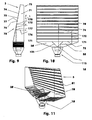
- FIGS. 9 and 10 show a front view and a side view of a lighting unit (5) with a surface light guide (70).
- a lighting unit (5) with a surface light guide (70).
- the one in these FIGS. 9 and 10 illustrated surface light guide (70) has the shape of a regular three-sided prism whose base (71) and top surface are parallel and congruent right triangles. It is for example a transparent plastic body, for example of the same material as the Lichtumlenk stresses (13) and / or the light distributor (30, 50).
- the underside (72) of the surface light guide (70) is e.g. a rectangular planar surface, which for example rests directly on the light exit surfaces (32, 52) of the light distributors (30, 50) and covers them.
- Perpendicular to this surface (72) is the e.g. designed as a flat surface front side (73) of the surface light guide (70).
- the height of the front side (73) of the surface light guide (70) shown shortened here is e.g. 80% larger than their length parallel to the light distributors (30, 50).
- the front side (73), which is the light exit surface (73) of the planar light guide (70), in this exemplary embodiment is twenty-five times the sum of the light exit surfaces (16, 19) of the light source (10).
- the light exit surface (73) can also be more than two hundred times as large as the sum of the light exit surfaces (16, 19).
- the rear side surface (74) of the surface light guide (70) has, for example, horizontal triangular notches (75).
- the length of the individual notches (75) is equal to the length of the surface light guide (70).
- These notches (75) are staggered at a constant distance from each other.
- the distance between the individual notches (75) is for example twice as large as the width of the individual notch (75), which is for example 0.5 mm to 1 mm.
- the two notched surfaces (76, 77) are in the representation of FIGS. 9 and 10 Plane surfaces.
- a normal to the lower notch surface (76) includes an imaginary straight line normal to the lower surface (72), eg an angle greater than or equal to the critical angle of total reflection for the material of the surface light guide (70) against air (76). 1).
- a further, not shown, light source can be arranged on the back (78) of the surface light guide (70).
- the direction of the light emitted from this light source is then, for example, at least approximately normal to the light exit surface (73) of the surface light guide (70).
- the light (101 - 108) emitted by the light source (10) is, for example, distributed in the light distributors (30, 50) as in connection with FIGS FIGS. 1-7 described.
- the luminous flux is largely the same.
- the light bundles (101 - 108) enter through the lower side (72) in the surface light guide (70). In the surface light guide (70) they meet the boundary surfaces, which are formed by the notched surfaces (76). In the FIGS. 9 and 10 For example, two possible light paths (171, 172) are shown. These light paths (171, 172), which are each partial light bundles of the light bundles (101 - 108), respectively illuminate part of the interfaces formed by the notched surfaces (76). The illuminated areas are light reflecting surfaces (176-178). The part of the luminous flux (101 - 108), which, for example, the light reflection surface (176) is tangent, so in the representation of FIG. 9 passing right on the light reflection surface (176), meets the next farther light reflection surface (177).
- the partial luminous fluxes (171-172) impinging on these light reflection surfaces (176-178), for example, are completely deflected in the direction of the front side (73) and pass through this light exit surface (73) into the environment (1).
- the viewer sees from a distance of about two to three meters, the homogeneous luminous front (73) of the surface light guide (70) with a uniform luminance distribution.
- the light source arranged on the back side (78) of the surface light guide (70) is switched on, the light emitted by this light source penetrates the surface light guide (70) largely unhindered. The viewer can clearly see this additional light source. Depending on the luminance of the light source (10) and the additional light source, either the overall luminance is increased or only one light source is perceived during simultaneous operation of both light sources.
- the surface light guide (70) may be curved.
- the front side (73) of the surface light guide (70) can form the outer contour of a vehicle.
- the light distributors (30, 50) of such a lighting unit (5) may have a e.g. have a curved shape adapted to a vehicle outer contour.
- FIG. 11 shows a lighting unit (5) with a surface light guide (70) whose reflection surfaces (176 - 178) have optical structures (81).
- These optical structures (81) are, for example, a multiplicity of ellipsoidal cutouts (82) which are arched towards the surroundings (1).
- the FIG. 8 shows a section of these optical structures (81), for example, as viewed from the bottom (72) of a transparent surface light guide (70).
- the longitudinal axis of the individual imaginary ellipsoids in this case lies, for example, parallel to the underside (72) and parallel to the front side (73) of the surface light guide (70).
- the ellipsoid cutouts (82) arranged on the individual reflection surfaces (176-178) are, for example, offset relative to one another.
- the light beams (101-108) incident on the reflection surfaces (176-178) are reflected at the optical structures (81).
- the reflected light is distributed in space so that, for example, a solid angle range of +/- 20 degrees in the horizontal direction and +/- 10 degrees in the vertical direction is illuminated.
- FIG. 12 an arrangement of three light units (5) is shown. These are arranged side by side, wherein, for example, the end faces of the surface light guides (70) adjoin one another. Hereby, for example, a large-scale light can be generated.
- a light source or it may be several light sources on the back (78) of the surface light guide (70) may be arranged.
- the in the FIGS. 1 . 2 . 9 - 12 illustrated light units (5) can be made in one piece.
- the entire lighting unit (5) form an injection molded part, in which the light source (10) is formed or to which the light source (10) is integrally formed.
- the light source (10) besides being a light emitting diode, may be an incandescent lamp, a halogen lamp, etc., may also be clipped to or connected to the light distributors (30, 50) or otherwise connected thereto.
- the optical element (113) which parallelizes the light (101 - 108) emitted by the light source (10) may also be part a light distributor or the light distributor (30, 50).
- the light (101 - 108) incident on the light distributor (135) can for example also be parallelized or collimated by means of an optical lens, eg a parabolic reflector etc.
- the lighting unit (5) When the light source (10) is turned off, the lighting unit (5) appears clear and unstructured. When the light source (10) is turned on, from the position of the observer, a uniform luminous surface appears without interference.
- the lighting unit (5) is compact and can be used as part of a combined tail light in a motor vehicle, for example.
- this may include a tail light with arranged behind the brake light and / or turn signals.
Description
- Die Erfindung betrifft eine Leuchteinheit mit mindestens einer Lichtquelle, mit mindestens einem der Lichtquelle optisch nachgeschalteten, Lichtreflexionsflächen aufweisenden Lichtteiler und mit mindestens einem den Lichtreflexionsflächen optisch nachgeschalteten Lichtumlenkbereich, wobei die Richtung des umgelenkten und den Lichtumlenkbereich verlassenden Lichts von der Lichtquelle weg zeigt.
- Aus der
EP 0 780 265 B1 ist eine derartige Leuchteinheit bekannt. Für den Betrachter erscheint der zentrale Bereich dunkel. - Die
FR-A-2 853 392 - Die
WO99/09349 A - Die
US-A-4 698 730 offenbart eine Lichtquelle, welche eine erhöhte Lichtausbeute ermöglicht, wobei das erzeugte Licht durch ein optisches Element, das der Lichtquelle nachgeschaltet ist, parallelisiert werden kann. - Der vorliegenden Erfindung liegt daher die Problemstellung zugrunde, eine kompakte Leuchteinheit zu entwickeln, die eine homogene Leuchtdichtenverteilung erzeugt.
- Diese Problemstellung wird mit den Merkmalen des Hauptanspruches gelöst. Dem Lichtteiler ist ein optisches Element optisch vorgeschaltet, das in der Lichtquelle erzeugtes Licht zumindest annähernd parallelisiert. Außerdem weist der Lichtteiler von der Lichtquelle durchleuchtete Lichtdurchtrittsflächen auf, die zumindest annähernd normal zur Richtung des parallelen Lichts liegen.
- Weitere Einzelheiten der Erfindung ergeben sich aus den Unteransprüchen und der nachfolgenden Beschreibung schematisch dargestellter Ausführungsformen.
- Figur 1:
- Schnitt durch eine Leuchteinheit mit Lichtquelle und Lichtverteilern;
- Figur 2:
- Dimetrische Ansicht eines Drahtmodells der Leuchteinheit nach
Figur 1 ; - Figur 3:
- Lichtquelle einer Leuchteinheit nach
Figur 1 ; - Figur 4:
- Detail eines Lichtteilers;
- Figur 5:
- Detail eines Lichtteilers;
- Figur 6:
- Detail eines Lichtumlenkbereichs;
- Figur 7:
- Detail eines Lichtumlenkbereichs;
- Figur 8:
- Detail optischer Umlenkstrukturen;
- Figur 9:
- Seitenansicht einer Leuchteinheit mit einem Flächenlichtleiter;
- Figur 10:
- Rückansicht einer Leuchteinheit nach
Figur 9 ; - Figur 11:
- Drahtmodell einer Leuchteinheit mit Umlenkstrukturen nach
Figur 8 ; - Figur 12:
- Anordnung mit drei Leuchteinheiten.
- Die
Figur 1 zeigt einen Schnitt durch eine Leuchteinheit (5) mit einer Lichtquelle (10) und mit zwei Lichtverteilern (30, 50). Diese Leuchteinheit (5) ist beispielsweise ein Teil einer in dieser Figur nicht weiter dargestellten Heckleuchte eines Kraftfahrzeuges. In derFigur 2 ist ein Drahtmodell dieser Leuchteinheit (5) in einer dimetrischen Ansicht und in derFigur 3 eine dimetrische Ansicht der Lichtquelle (10) dieser Leuchteinheit (5) dargestellt. - Die Lichtquelle (10) ist z.B. eine Leucht- oder Lumineszenzdiode (10). Sie umfasst einen lichtemittierenden Chip (11) mit elektrischen Anschlüssen (12) und einen Lichtumlenkkörper (13).
- Der Lichtumlenkkörper (13) ist ein z.B. transparenter, lichtbrechender Körper. Der Werkstoff des Lichtumlenkkörpers (13) ist beispielsweise ein thermoplastischer Kunststoff, z.B. PMMA, PMMI, etc., oder Glas. Der Lichtumlenkkörper (13) besteht z.B. aus einem Sockel (14) und aus einem Paraboloidstumpf (15), in dessen Brennpunkt beispielsweise der lichtemittierende Chip (11) liegt. Der Paraboloidstumpf (15) hat eine plane, ringförmige Lichtaustrittsfläche (19), die normal zur optischen Achse (22) der Lichtquelle (10) liegt. Die ringförmige Lichtaustrittsfläche (19) umgibt eine in den Paraboloidstumpf (15) eingesenkte zweite Lichtaustrittsfläche (16). Diese ist z.B. eine optische Linse (16), beispielsweise eine Sammellinse, sie kann z.B. als Fresnellinse ausgeführt sein. Um die optische Linse (16) herum liegt beispielsweise eine Hohlkehle (21). Der Abstand der gedachten Grundfläche (17) der optischen Linse (16) zum lichtemittierenden Chip (11) ist größer als die Brennweite der optischen Linse (16). Dieser Abstand entspricht etwa der Hälfte der Länge des Lichtumlenkkörpers (13) zwischen dem lichtemittierenden Chip (11) und der Lichtaustrittsfläche (19) der Leuchtdiode (10). Der äußere Durchmesser der Lichtaustrittsfläche (19), er beträgt beispielsweise 9 mm, ist in diesem Ausführungsbeispiel doppelt so groß wie der äußere Durchmesser der Hohlkehle (21).
- Die beiden Lichtverteiler (30, 50) sind beispielsweise achsensymmetrisch zur optischen Achse (22) der Lichtquelle (10) angeordnete Körper, deren in der
Figur 1 dargestellte Querschnittsfläche jeweils zumindest annähernd die Form eines Trapezes hat. Die beiden Lichtverteiler (30, 50) haben jeweils eine Lichteintrittsfläche (31, 51) und eine Lichtaustrittsfläche (32, 52). Diese Flächen (31, 32, 51, 52) sind hier parallel zueinander. Sie sind außerdem parallel zur Lichtaustrittsfläche (19) der Lichtquelle (10). Die Lichtaustrittsflächen (32, 52) sind jeweils um etwa 25% der Länge des einzelnen Lichtverteilers (30, 50) gegenüber der Lichteintrittsflächen (31, 51) von der optischen Achse (22) nach außen hin versetzt. Die Länge der Lichteintrittsfläche (31, 51) des einzelnen Lichtverteilers (30, 50), in der Darstellung derFigur 1 in Querrichtung zur optischen Achse (22), beträgt im Ausführungsbeispiel etwa 28% und die Länge der Lichtaustrittsfläche (32, 52) etwa 75% der Länge dieses Lichtverteilers (30, 50). Im diesem Ausführungsbeispiel beträgt die Summe der Längen beider Lichtverteiler (30, 50) beispielsweise 35 mm. Die Höhe des Lichtverteilers (30, 50) beträgt in der Darstellung derFiguren 1 und2 z.B. 26% der Länge dieses Körpers (30, 50). Die beiden Seitenflächen (33, 34; 53, 54) eines jeden Lichtverteilers (30, 50) sind zueinander parallel. - Die entgegengesetzt zueinander liegenden, nichtparallelen und in der Schnittdarstellung der
Figur 1 unterschiedlich langen Stirnseitenflächen (35, 36; 55, 56) der Lichtverteiler (30, 50) sind aus einzelnen Flächenelementen (37 - 39, 40 - 42; 57 - 59, 60 - 62) zusammengesetzt. Die jeweilige kurze Stirnseitenfläche (35; 55) besteht beispielsweise aus fünf schrägliegenden Flächenelementen (37; 57) und aus zwischen diesen Flächenelementen (37; 57) angeordneten weiteren vier Flächenelementen (38; 58) sowie aus Freiflächenelementen (39; 59), die an die Flächenelemente (38; 58) angrenzen. - Die Flächenelemente (37; 57) und die Lichteintrittsfläche (31) schließen beispielsweise einen Keilwinkel von 45 Grad ein. Die einzelnen Flächenelemente (37; 57) sind gleich groß und liegen in einer gemeinsamen Ebene.
- Die Flächenelemente (38; 58) grenzen beispielsweise an das in der
Figur 1 jeweils oberhalb liegende Flächenelement (37; 57) an. Diese Flächenelemente (38; 58) liegen parallel zur Lichteintrittsfläche (31; 51). Die einzelnen Flächenelemente (38; 58) sind beispielsweise gleich lang, ihre Länge beträgt z.B. 1,4% der Länge des Lichtverteilers (30; 50). In einer gedachten Projektion auf die Lichteintrittsflächen (31, 51) haben jeweils zwei benachbarte Flächenelemente (38; 58) zueinander einen Abstand von beispielsweise 5,8% der Länge eines Lichtverteilers (30; 50). - Die Flächenelemente (38; 58) ragen in der Darstellung der
Figur 1 aus den Stirnseitenflächen (35; 55) heraus. Je ein Freiflächenelement (39; 59), das z.B. normal zu den Flächenelementen (38; 58) liegt, verbindet ein Flächenelement (38; 58) mit einem unterhalb liegenden schrägliegenden Flächenelement (37; 57). - In den
Figuren 4 und 5 sind beispielsweise zwei weitere Ausführungsvarianten der Stirnseitenfläche (35) eines Lichtverteilers (30) gezeigt. In derFigur 4 sind die Flächenelemente (238) z.B. um 10% länger als die in derFigur 1 dargestellten Flächenelemente (38). Die Freiflächenelemente (239) und die Flächenelemente (238) begrenzen einen spitzwinkligen Keil. - Die
Figur 5 zeigt Flächenelemente (338), die in den Lichtverteiler (30) eingeprägt sind. Auch diese Flächenelemente (338) liegen beispielsweise parallel zur hier nicht dargestellten Lichteintrittsfläche des Lichtverteilers (30). Hierbei verbinden die Freiflächenelemente (339) jeweils ein Flächenelement (338) mit einem in der Darstellung derFigur 5 oberhalb angeordneten schrägliegenden Flächenelement (37). - Die langen Stirnseitenflächen (36, 56) der Lichtverteiler (30, 50) bestehen jeweils beispielsweise aus 25 angeordneten Flächenelementen (40 - 42; 60 - 62), vgl. die
Figuren 1 und2 . Eine Hälfte (40, 41; 60, 61) dieser Flächenelemente (40 - 42; 60 - 62) liegt z.B. gestaffelt angeordnet parallel zu den schrägliegenden Flächenelementen (37; 57) der kurzen Stirnseitenflächen (35; 55). Diese Flächenelemente (40, 41; 60, 61) werden im folgenden als Stufenflächenelemente (40, 41; 60, 61) bezeichnet. Die anderen, ebenfalls gestaffelt angeordneten Flächenelemente (42; 62) sind Freiflächenelemente und verbinden die Flächenelemente (40, 41; 60, 61) miteinander. Die Freiflächenelemente (42; 62) schließen mit jeweils einem in einer Scheitelstrecke (44; 64) angrenzenden Stufenflächenelement (40, 41; 60, 61) einen Winkel ein, der beispielsweise kleiner ist als 135 Grad. - Bei einer gedachten Projektion auf die Ebene der Lichteintrittsflächen (31, 51) haben in der Darstellung der
Figur 1 je zwei benachbarte Scheitelstrecken (44; 64) zueinander beispielsweise den gleichen Abstand. - Die Stufenflächenelemente (40, 41; 60, 61) haben in den in den in den
Figuren 1 und2 dargestellten Lichtverteilern (30, 50) zwei unterschiedliche Größen. So sind in derFigur 1 beispielsweise - von der Lichteintrittsfläche (31; 51) gezählt - die vierte, die siebte die zehnte und die dreizehnte Stufenfläche (41; 61) um 50% größer als die übrigen Stufenflächen (40; 60). Jede zur Lichteintrittsfläche (31; 51) parallele gedachte Gerade in Längsrichtung des Lichtverteilers (30; 50) durch ein Freiflächenelement (39; 59) der kurzen Stirnseitenfläche (35) schneidet im Ausführungsbeispiel derFigur 1 ein großes Stufenflächenelement (41; 61) der langen Stirnseitenfläche (36). - In den
Figuren 6 und 7 sind weitere Ausführungsformen einer langen Stirnseitenfläche (36) dargestellt. Die Anzahl und die Winkellage der Stufenflächenelemente (240, 241; 340, 341) ist beispielsweise identisch der in denFiguren 1 und2 gezeigten Ausführungsform. In derFigur 6 ist der Abstand der auf die Ebene der Lichteintrittsfläche (31) projizierten Scheitelstrecken (244, 245) nicht konstant. Die Scheitelstrecken (244) begrenzen die kleinen Stufenflächenelementen (240), die Scheitelstrecken (245) liegen an den großen Stufenflächenelementen (241). In diesem Ausführungsbeispiel sind die großen Stufenflächenelemente (241) um 87% größer als die kleinen Stufenflächenelemente (240). - Auch der in der
Figur 7 dargestellte Lichtverteiler (30) hat Stufenflächen (340, 341) unterschiedlicher Größe. Hierbei sind die großen Stufenflächenelemente (341) beispielsweise 80% größer als die kleinen Stufenflächenelemente (340). Alle Scheitelstrecken (344), die ein großes Stufenflächenelement (341) begrenzen, haben in einer Projektion auf die Ebene der Lichteintrittsseite (31) beispielsweise zu beiden benachbarten, je ein großes Stufenflächenelement (341) begrenzenden Scheitelstrecken (344) denselben Abstand. - Der einzelne Lichtverteiler (30; 50) kann Kombinationen der beschriebenen Ausführungsformen aufweisen. So kann er beispielsweise eine kurze Stirnseitenfläche (35; 55) nach
Figur 4 und eine lange Stirnseitenfläche (36; 56) nachFigur 7 haben. - Auch können die Stirnseitenflächen (35, 36; 55, 56) abschnittsweise unterschiedliche Gestaltungen haben.
- Der Abstand der beiden Lichtverteiler (30; 50) zueinander, die Länge des Spalts (49), entspricht der Länge eines der in
Figur 1 dargestellten Flächenelemente (38; 58). Die beiden Lichtverteiler (30; 50) können auch miteinander verbunden sein, z.B. mittels eines zentralen Stegs konstanter Stärke. Statt zweier Lichtverteiler (30; 50) kann beispielsweise auch ein einzelner rotationssymmetrischer Lichtverteiler eingesetzt werden. Die Rotationsachse ist in diesem Fall beispielsweise die optische Achse (22) der Lichtquelle (10). - Beim Betrieb der Leuchteinheit (5) wird in der Lichtquelle (10) Licht (101 - 108) vom lichtemittierenden Chip (11) erzeugt. Ein Teil des in der
Figur 1 gestrichelt dargestellten, vom lichtemittierenden Chip (11) emittierten Lichts (101 - 108) trifft auf die Grenzfläche des Lichtumlenkkörpers (13), der durch die Sammellinse (16) gebildet wird. Der Winkel, der durch das auftreffende Licht und eine Normale im Auftreffpunkt eingeschlossen wird, ist kleiner als der Grenzwinkel der Totalreflexion. Dieser Grenzwinkel beträgt bei PMMA beispielsweise 42 Grad. Das auftreffende Licht tritt durch die Sammellinse hindurch, wobei es in Richtung der optischen Achse (22) gebrochen wird. Das aus der Sammellinse (16) austretende Licht liegt parallel zur optischen Achse (22) der Leuchteinheit (5). - Der Teil des vom lichtemittierenden Chip (11) emittierten Lichts (101 - 108), der nicht durch die Sammellinse (16) hindurchtritt, trifft auf die Grenzfläche des Lichtumlenkkörpers (13), die durch die Mantelfläche des Paraboloidstumpfes (15) gebildet wird. Der Auftreffwinkel ist größer als der Grenzwinkel der Totalreflexion. Dieser Teil des Lichtbündels (101 - 108) wird vollständig in Richtung der Lichtaustrittsfläche (19) reflektiert. Es durchtritt die Lichtaustrittsfläche (19) in normaler Richtung und liegt ebenfalls parallel zur optischen Achse (22) der Lichtquelle (10). Der Lichtumlenkkörper (13) der Lichtquelle (10) parallelisiert bzw. kollimiert das vom lichtemittierenden Chip (11) emittierte Licht (101 - 108). Er wirkt somit für das Licht (101 - 108) als Kollimator (113). Die Richtung (9) des von der Lichtquelle (10) emittierten parallelisierten Lichts (101 - 108) ist beispielsweise parallel zur optischen Achse (22) der Lichtquelle (10).
- Das parallelisierte Licht (101 - 108) tritt durch die Lichteintrittsflächen (31, 51) in die Lichtverteiler (30, 50). In den Lichtverteilern (30, 50) trifft es auf die Grenzflächen, die durch die kurzen Stirnseiten (35, 55) gebildet werden. Diese beiden Grenzflächen bilden für das Lichtbündel (101 - 108) einen Lichtteiler (135).
- Das Lichtbündel (101 - 108) trifft auf den Lichtteiler (135) sowohl in den Abschnitten auf, in denen die in der
Figur 1 waagerecht dargestellten Flächenelemente (38, 58) den jeweiligen Lichtverteiler (30, 50) begrenzen, als auch auf den Spalt (49) zwischen den Lichtverteilern (30, 50) und in den Abschnitten, in denen die in dieser Figur schräg liegenden Flächenelemente (37, 57) die Körperbegrenzung bilden. Das in den waagerecht dargestellten Abschnitten (38, 58) normal auf die Grenzfläche auftreffende Licht (104, 108) tritt durch diese Grenzflächen hindurch in die Umgebung (1). Die von der Lichtquelle (10) ausgeleuchteten Bereiche dieser Grenzflächen sind Lichtdurchtrittsflächen (138). Diese Lichtdurchtrittsflächen (138) liegen zumindest annähernd normal zur Richtung (9) des parallelen Lichts (101 - 108). Auch der Spalt (49) bildet eine Lichtdurchtrittsfläche (138), durch den ein Lichtbündel (101) in die Umgebung (1) austritt. Alle Lichtdurchtrittsflächen (138) haben in einer Projektion entgegen der Richtung des parallelisierten Lichts (101 - 108) die gleiche Größe und zu jeweils zwei benachbarten Lichtdurchtrittsflächen (138) den gleichen Abstand. - Lichtbündel (102, 103, 105 - 107), die auf die durch die schräg dargestellten Flächenelemente (37, 57) gebildeten Grenzflächen auftreffen, treffen hier unter einem Winkel zur Normalen auf die Grenzfläche auf, der größer ist als der Grenzwinkel der Totalreflexion des Werkstoffs des jeweiligen Lichtverteilers (30, 50) gegen Umgebungsluft (1). Diese Grenzflächen bilden Lichtreflexionsflächen (137), an denen das auftreffende Licht (102, 103, 105 - 107) beispielsweise vollständig in Längsrichtung des jeweiligen Lichtteilers (30, 50) umgelenkt wird. Nach der Reflexion liegen die Lichtbündel (102, 103, 105 - 107) wieder parallel zueinander. Zwischen den Lichtbündeln (102, 103, 105 - 107) liegen nicht ausgeleuchtete Lücken (111), da das durch die Lichtdurchtrittsflächen (138) durchtretende Licht (101, 104, 108) nicht umgelenkt wird. Die durch die Freiflächenelemente (39) gebildeten Grenzflächen der Lichtverteiler (30, 50) werden nicht ausgeleuchtet.
- Ist der Lichtverteiler (30; 50) wie in den
Figuren 4 oder 5 gestaltet, wird das von der Lichtquelle (10) emittierte Licht (101 - 108) an dem in diesen Figuren gezeigten Lichtteilerabschnitt (135) zumindest ähnlich aufgeteilt wie bei dem in derFigur 1 dargestellten Lichtteiler (135). In denFiguren 4 und 5 ist beispielsweise von den parallelisierten, einander tangierenden Lichtbündeln (103 - 108) zur Veranschaulichung jeweils nur der zentrale Bereich dargestellt. Bei einer Ausführung nachFigur 4 wird das durch die Lichtdurchtrittsflächen (138) durchtretende Licht (104, 108) aufgrund der rückspringenden Freiflächen (239) z.B. nicht reflektiert oder gebrochen. Die Lichtdurchtrittsflächen (138) sind in dem Ausführungsbeispiel nachFigur 4 nur die Bereiche der durch die Flächenelemente (238) gebildeten Grenzflächen, die von der Lichtquelle (10) ausgeleuchtet werden. - Die am Lichtteiler (135) umgelenkten Lichtbündel (102, 103, 105 - 107) treffen auf die gestaffelt angeordneten Grenzflächen des jeweiligen Lichtverteilers (30; 50), die durch die Stufenflächenelemente (40, 41) gebildet werden, vgl.
Figur 1 . Hierbei werden diese Grenzflächen nur teilweise ausgeleuchtet. Die ausgeleuchteten Bereiche sind Lichtumlenkflächen (142, 143, 145 - 147) eines Lichtumlenkbereichs (140), an denen die Lichtbündel (102, 103, 105 - 107) in der Richtung der Lichtaustrittsfläche (32; 52) reflektiert werden. Das Lichtbündel (102) trifft hierbei beispielsweise auf die Lichtumlenkfläche (142) auf, das Lichtbündel (103) auf die Lichtumlenkfläche (143) und das Lichtbündel (105) auf eine Lichtumlenkfläche (145). Letztere ist z.B. Teil einer durch ein großes Stufenflächenelement (41; 61) gebildeten Grenzfläche. Das Lichtbündel (103), das z.B. in der Darstellung derFigur 1 oberhalb des Lichtbündels (102) liegt, tangiert die Lichtumlenkfläche (142) und trifft auf die nächst weiter vom Lichtteiler (135) entfernt liegende Lichtumlenkfläche (143). In einer Projektion entgegen der Richtung der an den Lichtumlenkflächen (142, 143, 145 - 147) umgelenkten Lichtanteile (102, 103, 105 - 107) ist der Abstand der Lichtumlenkflächen (142, 143, 145 - 147) zueinander gleich. Dieser Abstand entspricht in dieser Projektion auch dem Abstand der Lichtdurchtrittsflächen (138) zueinander und zu den Lichtumlenkflächen (142, 143, 145 - 147). Die Flächen (138, 142, 143, 145 - 147) haben in der Projektion beispielsweise die gleiche Größe. Die durch die Freiflächenelemente (42; 62) gebildeten Grenzflächen beeinflussen das Licht (102, 103, 105 - 107) nicht, es erfolgt beispielsweise keine Reflexion oder Brechung der Lichtbündel (102, 103, 105 -107). Die den Lichtteiler (135) durchtretenden und die im Umlenkbereich (140) umgelenkten Lichtbündel (101 - 108), die an der Lichtaustrittsseite (32; 52) austreten, haben zueinander den gleichen Abstand und den gleichen Querschnitt. Sie haben in diesem Ausführungsbeispiel die gleiche Richtung (9) wie das von der Lichtquelle (10) emittierte Licht (101 - 108). Die Lücken (111) treten nicht auf und sind für den Betrachter nicht sichtbar. Das aus der in denFiguren 1 und2 austretende Licht (101 - 108) wird flächenmäßig anteilsmäßig gleich aufgeteilt. Beim Beobachten aus einer geeigneten Entfernung erzeugt es den Eindruck einer gleichmäßig verteilten Leuchtdichte. - Bei einer Ausführung der Lichtverteiler (30; 50) nach einer der
Figuren 6 oder 7 wird im Lichtumlenkbereich (140) ebenfalls die Lücke (111) überbrückt, so dass sich eine gleichmä-βige Leuchtdichtenverteilung ergibt. Bei einer Ausführung nachFigur 6 wird z.B. die Lichtumlenkfläche (143) durch ein großes Stufenflächenelement (241) gebildet, während die Lichtumlenkflächen (142, 145 - 147) durch kleine Stufenflächenelemente (240) gebildet werden. - In der
Figur 7 sind alle Lichtumlenkflächen (142, 143, 145 - 147) Teile von Grenzflächen, die durch große Stufenflächenelemente (341) gebildet werden. - Die Größe der Lichtumlenkflächen (142, 143, 145 - 147) kann beispielsweise mit zunehmendem Abstand vom Lichtteiler (135) zunehmen. Die entgegen der Richtung des aus den Lichtaustrittsflächen (32; 52) austretenden Lichts (101 - 108) projizierten Mittellinien der Lichtumlenkflächen (142, 143, 145 - 147) haben dann beispielsweise den gleichen Abstand zueinander. Bei großen Lichtverteilern (30; 50) kann so z.B. die Schwächung der Lichtstärke durch die Werkstoffabsorption kompensiert werden.
- Die so projizierten Lichtumlenkflächen (142, 143, 145 - 147) und Lichtdurchtrittsflächen (138) können auch unterschiedlich groß sein. So können beispielsweise bei einer Leuchtdiode (10) Bereiche unterschiedlicher Lichtstärke ausgeglichen werden. Beispielsweise können Bereiche großer Lichtstärke kleine Lichtumlenkflächen (142, 143, 145 - 147) und Lichtdurchtrittsflächen (138) ausleuchten, während Bereiche kleiner Lichtstärke große Flächen (138, 142, 143, 145 - 147) beleuchten.
- Der Lichtteiler (135) und die Lichtumlenkflächen (142, 143, 145 - 147) können Teile unterschiedlicher Körper sein. Beispielsweise können die Lichtreflexionsflächen (137) des Lichtteilers (135) um die Lichtumlenkflächen (142, 143, 145 - 147) Spiegelflächen einzelner, ggf. einstellbarer Spiegel sein.
- Die
Figuren 9 und 10 zeigen eine Vorderansicht und eine Seitenansicht einer Leuchteinheit (5) mit einem Flächenlichtleiter (70). Als Lichtquelle (10) und als Lichtverteiler (30, 50) sind beispielsweise die in denFiguren 1 und2 beschriebenen Bauelemente eingesetzt. - Der in diesen
Figuren 9 und 10 dargestellte Flächenlichtleiter (70) hat die Gestalt eines regulären dreiseitigen Prismas, dessen Grund- (71) und Deckfläche parallele und kongruente rechtwinklige Dreiecke sind. Er ist beispielsweise ein transparenter Kunststoffkörper, z.B. aus dem gleichen Werkstoff wie der Lichtumlenkkörper (13) und/oder der Lichtverteiler (30, 50) . - Die Unterseite (72) des Flächenlichtleiters (70) ist z.B. eine rechteckige Planfläche, die beispielsweise unmittelbar auf den Lichtaustrittsflächen (32, 52) der Lichtverteiler (30, 50) aufliegt und diese abdeckt.
- Senkrecht zu dieser Fläche (72) steht die z.B. als Planfläche ausgeführte Vorderseite (73) des Flächenlichtleiters (70). Die Höhe der Vorderseite (73) des hier gekürzt dargestellten Flächenlichtleiters (70) ist z.B. 80% größer als ihre Länge parallel zu den Lichtverteilern (30, 50). Die Vorderseite (73), die die Lichtaustrittsfläche (73) des Flächenlichtleiters (70) ist, ist in diesem Ausführungsbeispiel fünfundzwanzig mal so groß wie die Summe der Lichtaustrittsflächen (16, 19) der Lichtquelle (10). Die Lichtaustrittsfläche (73) kann auch mehr als zweihundertmal so groß sein wie die Summe der Lichtaustrittsflächen (16, 19)
- Die Rückseitenfläche (74) des Flächenlichtleiters (70) hat z.B. waagerecht liegende dreieckige Kerben (75). Die Länge der einzelnen Kerben (75) ist gleich der Länge des Flächenlichtleiters (70). Diese Kerben (75) sind gestaffelt mit konstantem Abstand zueinander angeordnet. Der Abstand zwischen den einzelnen Kerben (75) ist beispielsweise doppelt so groß wie die Breite der einzelnen Kerbe (75), die z.B. 0,5 mm bis 1 mm beträgt. Die beiden Kerbflächen (76, 77) sind in der Darstellung der
Figuren 9 und 10 Planflächen. Eine Normale auf die untere Kerbfläche (76) schließt mit einer gedachten Geraden, die normal zur Unterseite (72) liegt, z.B. einen Winkel ein, der grö-βer oder gleich dem Grenzwinkel der Totalreflexion für den Werkstoff des Flächenlichtleiters (70) gegen Luft (1) ist. - Auf der Rückseite (78) des Flächenlichtleiters (70) kann eine weitere, hier nicht dargestellte Lichtquelle angeordnet sein. Die Richtung des von dieser Lichtquelle emittierten Lichts ist dann beispielsweise zumindest annähernd normal zur Lichtaustrittsfläche (73) des Flächenlichtleiters (70).
- Beim Betrieb der Leuchteinheit (5) wird das von der Lichtquelle (10) emittierte Licht (101 - 108) beispielsweise in den Lichtverteilern (30, 50) so aufgeteilt, wie im Zusammenhang mit den
Figuren 1 - 7 beschrieben. In den einzelnen, parallel zueinander liegenden Lichtbündeln (101 - 108) ist der Lichtstrom weitgehend gleich. - Die Lichtbündel (101 - 108) treten durch die Unterseite (72) in den Flächenlichtleiter (70) ein. Im Flächenlichtleiter (70) treffen sie auf die Grenzflächen, die durch die Kerbflächen (76) gebildet werden. In den
Figuren 9 und 10 sind beispielsweise zwei mögliche Lichtpfade (171, 172) dargestellt. Diese Lichtpfade (171, 172), die jeweils Teillichtbündel der Lichtbündel (101 - 108) sind, leuchten jeweils einen Teil der durch die Kerbflächen (76) gebildeten Grenzflächen aus. Die ausgeleuchteten Flächen sind Lichtreflexionsflächen (176 - 178). Der Teil des Lichtstroms (101 - 108), der beispielsweise die Lichtreflexionsfläche (176) tangiert, also in der Darstellung derFigur 9 rechts an der Lichtreflexionsfläche (176) vorbeigeht, trifft auf die nächst weiter entfernte Lichtreflexionsfläche (177). - Die auf diese Lichtreflexionsflächen (176 - 178) auftreffenden Teillichtströme (171 - 172) werden beispielsweise vollständig in Richtung der Vorderseite (73) umgelenkt und treten durch diese Lichtaustrittsfläche (73) hindurch in die Umgebung (1).
- Der Betrachter sieht aus einem Abstand von etwa zwei bis drei Metern die homogen leuchtende Vorderseite (73) des Flächenlichtleiters (70) mit einer gleichmäßigen Leuchtdichtenverteilung.
- Wird zusätzlich die auf der Rückseite (78) des Flächenlichtleiters (70) angeordnete Lichtquelle eingeschaltet, durchdringt das von dieser Lichtquelle emittierte Licht den Flächenlichtleiter (70) weitgehend ungehindert. Der Betrachter kann diese zusätzliche Lichtquelle klar erkennen. Je nach Leuchtdichte der Lichtquelle (10) und der zusätzlichen Lichtquelle wird bei gleichzeitigem Betrieb beider Lichtquellen entweder die Gesamtleuchtdichte erhöht oder nur eine Lichtquelle wahrgenommen.
- Auf der Rückseite (78) des Flächenlichtleiters (70) können auch mehrere Lichtquellen angeordnet sein.
- Der Flächenlichtleiter (70) kann gewölbt sein. So kann die Vorderseite (73) des Flächenlichtleiters (70) beispielsweise die Außenkontur eines Fahrzeuges bilden. Auch die Lichtverteiler (30, 50) einer derartigen Leuchteinheit (5) können eine z.B. an eine Fahrzeugaußenkontur angepasste gewölbte Gestalt aufweisen.
- Die
Figur 11 zeigt eine Leuchteinheit (5) mit einem Flächenlichtleiter (70), dessen Reflexionsflächen (176 - 178) optische Strukturen (81) aufweisen. Diese optischen Strukturen (81) sind beispielsweise eine Vielzahl zur Umgebung (1) hin gewölbter Ellipsoidenausschnitte (82). - Die
Figur 8 zeigt einen Ausschnitt dieser optischen Strukturen (81), z.B. betrachtet von der Unterseite (72) eines transparenten Flächenlichtleiters (70) aus. Die Längsachse der einzelnen gedachten Ellipsoide liegt hierbei beispielsweise parallel zur Unterseite (72) und parallel zur Vorderseite (73) des Flächenlichtleiters (70). Hierbei sind die für die auftreffenden Lichtbündel (101 - 108) hintereinander angeordneten Reflexionsflächen (176 - 178) übereinander dargestellt. Die auf den einzelnen Reflexionsflächen (176 - 178) angeordneten Ellipsoidenausschnitte (82) sind beispielsweise versetzt zueinander angeordnet. - Die auf die Reflexionsflächen (176 - 178) auftreffenden Lichtbündel (101 - 108) werden an den optischen Strukturen (81) reflektiert. Das reflektierte Licht wird im Raum so verteilt, dass beispielsweise ein Raumwinkelbereich von +/- 20 Winkelgraden in horizontaler Richtung und +/- 10 Winkelgraden in vertikaler Richtung ausgeleuchtet wird.
- In der
Figur 12 ist eine Anordnung von drei Leuchteinheiten (5) dargestellt. Diese sind nebeneinander angeordnet, wobei z.B. die Stirnflächen der Flächenlichtleiter (70) aneinander angrenzen. Hiermit kann beispielsweise eine großflächige Leuchte erzeugt werden. Selbstverständlich kann bei dieser Anordnung eine Lichtquelle oder es können mehrere Lichtquellen an der Rückseite (78) des Flächenlichtleiters (70) angeordnet sein. - Die in den
Figuren 1 ,2 ,9 - 12 dargestellten Leuchteinheiten (5) können einteilig ausgeführt sein. So kann die gesamte Leuchteinheit (5) ein Spritzgussteil bilden, in das die Lichtquelle (10) eingeformt ist oder an das die Lichtquelle (10) angeformt ist. Die Lichtquelle (10), sie kann außer einer Leuchtdiode eine Glühlampe, Halogenlampe, etc. sein, kann auch an den oder an die Lichtverteiler (30, 50) angeclipst sein oder auf sonstige Weise mit diesen verbunden sein. - Das optische Element (113), das das von der Lichtquelle (10) emittierte Licht (101 - 108) parallelisiert, kann auch Teil eines Lichtverteilers oder der Lichtverteiler (30, 50) sein. Das auf den Lichtverteiler (135) auftreffende Licht (101 - 108) kann beispielsweise auch mittels einer optische Linse, einem z.B. parabolischen Reflektors etc. parallelisiert bzw. kollimiert werden.
- Bei ausgeschalteter Lichtquelle (10) erscheint die Leuchteinheit (5) klar und unstrukturiert. Wird die Lichtquelle (10) eingeschaltet, erscheint aus der Position des Beobachters eine gleichmäßig leuchtende Fläche ohne Störungen.
- Die Leuchteinheit (5) ist kompakt aufgebaut und kann so z.B. als Teil einer kombinierten Heckleuchte in einem Kraftfahrzeug eingesetzt werden. Beispielsweise kann diese ein Schlusslicht mit dahinter angeordneter Bremsleuchte und/oder Blinker umfassen.
- Bezugszeichenliste:
- 1
- Umgebung, Luft
- 5
- Leuchteinheit
- 9
- Richtung des emittierten parallelisierten Lichts
- 10
- Lichtquelle, Leuchtdiode
- 11
- lichtemittierenden Chip
- 12
- elektrische Anschlüsse
- 13
- Lichtumlenkkörper
- 14
- Sockel
- 15
- Paraboloidstumpf
- 16
- optische Linse, Lichtaustrittsfläche von (10), Sammellinse
- 17
- Grundfläche von (16)
- 18
- Brennpunkt von (16)
- 19
- Lichtaustrittsfläche, ringförmig von (10)
- 21
- Hohlkehle
- 22
- optische Achse von (10)
- 30, 50
- Lichtverteiler
- 31, 51
- Lichteintrittsflächen
- 32, 52
- Lichtaustrittsflächen
- 33, 53
- Seitenflächen
- 34, 54
- Seitenflächen
- 35, 55
- Stirnseitenfläche, kurz von (30; 50)
- 36, 56
- Stirnseitenfläche, lang von (30; 50)
- 37, 57
- Flächenelemente, schrägliegend
- 38, 58
- Flächenelemente, normal zu (9)
- 39, 59
- Freiflächenelemente
- 40, 60
- Flächenelemente, klein; Stufenflächenelemente
- 41, 61
- Flächenelemente, groß; Stufenflächenelemente
- 42, 62
- Flächenelemente, Freiflächenelemente
- 44, 64
- Scheitelstrecken
- 49
- Spalt
- 70
- Flächenlichtleiter
- 71
- Grundfläche
- 72
- Unterseite, Planfläche
- 73
- Vorderseite, Lichtaustrittsfläche
- 74
- Rückseitenfläche
- 75
- Kerben
- 76
- Kerbflächen
- 77
- Kerbflächen
- 78
- Rückseite von (70)
- 81
- optische Strukturen
- 82
- Ellipsoidenausschnitte
- 101 - 108
- Licht, Lichtbündel
- 111
- Lücken
- 113
- Parallelisierendes optisches Element, Kollimator
- 135
- Lichtteiler
- 137
- Lichtreflexionsflächen
- 138
- Lichtdurchtrittsflächen
- 140
- Lichtumlenkbereich
- 142, 143
- Lichtumlenkflächen
- 145 - 147
- Lichtumlenkflächen
- 171
- Lichtpfad
- 172
- Lichtpfad
- 176 - 178
- Lichtreflexionsflächen
- 238
- Flächenelemente
- 239
- Freiflächenelemente
- 240
- kleine Stufenflächenelemente
- 241
- große Stufenflächenelemente
- 244
- Scheitelstrecken an (240)
- 245
- Scheitelstrecken an (241)
- 338
- Flächenelemente
- 339
- Freiflächenelemente
- 340
- kleine Stufenflächenelemente
- 341
- große Stufenflächenelemente
- 344
- Scheitelstrecken
Claims (17)
- Leuchteinheit (5) mit mindestens einer Lichtquelle (10), mit mindestens einem der Lichtquelle (10) optisch nachgeschalteten, Lichtreftexionsflächen (137) aufweisenden Lichtteiler (135) und mit mindestens einem den Lichtreflexionsflächen (137) optisch nachgeschalteten Lichtumlenkbereich (140), wobei die Richtung des umgelenkten und den Lichtumlenkbereich (140) verlassenden Lichts von der Lichtquelle (10) weg zeigt, wobei dem Lichtteiler (135) ein optisches Element (113) optisch vorgeschaltet ist, das in der Lichtquelle (10) erzeugtes Licht (101 - 108) zumindest annähernd parallelisiert und wobei der Lichtteiler (135) von der Lichtquelle (10) durchleuchtete Lichtdurchtrittsflächen (138) aufweist, die zumindest annähernd normal zur Richtung (9) des parallelen Lichts (101 - 108) liegen, dadurch gekennzeichnet, dass den Lichtumlenkflächen (142, 143, 145 -147) des Lichtumlenkbereichs (140) und den Lichtdurchtrittsflächen (138) ein Flächenlichtleiter (70) optisch nachgeschaltet ist.
- Leuchteinheit nach Anspruch 1, dadurch gekennzeichnet, dass das optische Element (113) Teil der Lichtquelle (10) ist.
- Leuchteinheit nach Anspruch 1, dadurch gekennzeichnet, dass der Lichtumlenkbereich (140) gestaffelt angeordnete Lichtumlenkflächen (142, 143, 145 - 147) aufweist.
- Leuchteinheit nach Anspruch 1, dadurch gekennzeichnet, dass zumindest eine Lichtreflexionsfläche (137), mindestens eine Lichtdurchtrittsfläche (138) und zumindest eine Lichtumlenkfläche (142; 143; 145; 146; 147) Grenzflächen eines Lichtverteilers (30; 50) sind.
- Leuchteinheit nach Anspruch 4, dadurch gekennzeichnet, dass zumindest ein Lichtverteiler (30; 50) eine plane Lichteintrittsseite (31; 51) aufweist.
- Leuchteinheit nach Anspruch 4, dadurch gekennzeichnet, dass die Größe der Lichtumlenkflächen (142, 143, 145 - 147) mit zunehmendem Abstand vom Lichtteiler (135) zunimmt.
- Leuchteinheit nach Anspruch 1, dadurch gekennzeichnet, dass die Richtung (9) des von der Lichtquelle emittierten Lichts zumindest annähernd gleich der Richtung des umgelenkten und den Lichtumlenkbereich (140) verlassenden Lichts (102, 103, 105 - 107) ist.
- Leuchteinheit nach Anspruch 1, dadurch gekennzeichnet, dass die Richtung des im Lichtumlenkbereich (140) umgelenkten Lichts (102, 103, 105 - 107) gleich der Richtung des die Lichtdurchtrittsflächen (138) durchtretenden Lichts (101, 104, 108) ist.
- Leuchteinheit nach Anspruch 3, dadurch gekennzeichnet, dass in einer Projektion entgegen der Richtung der an den Lichtumlenkflächen (142, 143, 145 -147) umgelenkten Lichtbündel (102, 103, 105 - 107) der Abstand der Lichtumlenkflächen (142, 143, 145 - 147) zueinander gleich ist.
- Leuchteinheit nach Anspruch 8 und 9, dadurch gekennzeichnet, dass in einer Projektion entgegen der Richtung der an den Lichtumlenkflächen (142, 143, 145 -147) umgelenkten Lichtbündel (102, 103, 105 - 107) der Abstand der Lichtdurchtrittsflächen (138) und der Lichtumlenkflächen (142, 143, 145 - 147) zueinander gleich ist.
- Leuchteinheit nach Anspruch 1, dadurch gekennzeichnet, dass die Lichtquelle (10) Bereiche unterschiedlicher Lichtstärke hat und dass Bereiche hoher Lichtstärke kleine Lichtumlenkflächen (142, 143, 145 - 147) und Lichtdurchtrittsflächen (138) ausleuchten.
- Leuchteinheit nach Anspruch 1, dadurch gekennzeichnet, dass die Lichtquelle eine Leuchtdiode (10) ist.
- Leuchteinheit nach Anspruch 12, dadurch gekennzeichnet, dass die Leuchtdiode (10) einen paraboloidförmigen Lichtumlenkkörper (13) umfasst.
- Leuchteinheit nach den Ansprüchen 4 und 12, dadurch gekennzeichnet, dass die Leuchtdiode (10) in mindestens einen Lichtverteiler (30; 50) integriert ist.
- Leuchteinheit nach Anspruch 1, dadurch gekennzeichnet, dass die Lichtaustrittsfläche (73) des Flächenlichtleiters (70) mindestens zwanzigmal so groß ist wie die Lichtaustrittsflächen (16, 19) der Lichtquelle (10).
- Leuchteinheit nach Anspruch 15, dadurch gekennzeichnet, dass der Flächenlichtleiter (70) transparent ist und optische Strukturen (81) umfasst.
- Leuchteinheit nach Anspruch 15, dadurch gekennzeichnet, dass sie eine weitere Lichtquelle umfasst, die Licht in einer Richtung zumindest annähernd normal zur Lichtaustrittsfläche (73) des Flächenlichtleiters (70) emittiert.
Priority Applications (1)
| Application Number | Priority Date | Filing Date | Title |
|---|---|---|---|
| SI200630874T SI1684002T1 (sl) | 2005-01-24 | 2006-01-12 | Svetilo s svetlobnim razdelilnikom |
Applications Claiming Priority (1)
| Application Number | Priority Date | Filing Date | Title |
|---|---|---|---|
| DE102005003367A DE102005003367B4 (de) | 2005-01-24 | 2005-01-24 | Leuchteinheit mit Lichtteiler |
Publications (3)
| Publication Number | Publication Date |
|---|---|
| EP1684002A2 EP1684002A2 (de) | 2006-07-26 |
| EP1684002A3 EP1684002A3 (de) | 2008-09-17 |
| EP1684002B1 true EP1684002B1 (de) | 2010-11-03 |
Family
ID=35892460
Family Applications (1)
| Application Number | Title | Priority Date | Filing Date |
|---|---|---|---|
| EP06000553A Active EP1684002B1 (de) | 2005-01-24 | 2006-01-12 | Leuchteinheit mit Lichtteiler |
Country Status (5)
| Country | Link |
|---|---|
| US (1) | US7431481B2 (de) |
| EP (1) | EP1684002B1 (de) |
| KR (1) | KR20060085566A (de) |
| DE (2) | DE102005003367B4 (de) |
| SI (1) | SI1684002T1 (de) |
Families Citing this family (76)
| Publication number | Priority date | Publication date | Assignee | Title |
|---|---|---|---|---|
| DE102006008191B4 (de) * | 2006-02-22 | 2015-10-08 | Hella Kgaa Hueck & Co. | Leuchteneinheit für Fahrzeuge |
| DE102007013082A1 (de) * | 2007-03-14 | 2008-09-18 | Hella Kgaa Hueck & Co. | Signalleuchte |
| JP4968784B2 (ja) * | 2007-04-09 | 2012-07-04 | シチズン電子株式会社 | 光学部材の作製方法及び照明装置の作製方法 |
| JP4458125B2 (ja) * | 2007-07-25 | 2010-04-28 | 船井電機株式会社 | インジケータ装置およびテレビジョン装置 |
| CN101359122B (zh) * | 2007-08-03 | 2011-05-04 | 清华大学 | 背光模组 |
| US20090207610A1 (en) * | 2008-02-19 | 2009-08-20 | Edwin Mitchell Sayers | Combination rear lighting system |
| JP5070129B2 (ja) * | 2008-05-22 | 2012-11-07 | 株式会社小糸製作所 | 車両用照明灯具 |
| WO2009144668A1 (en) * | 2008-05-30 | 2009-12-03 | Koninklijke Philips Electronics N.V. | Illumination device comprising a collimator |
| DE102008061716A1 (de) * | 2008-12-12 | 2010-06-17 | Bayerische Motoren Werke Aktiengesellschaft | Fahrzeugleuchte und Leuchtensystem |
| DE102009010507A1 (de) * | 2009-02-25 | 2010-08-26 | Daimler Ag | Beleuchtungseinrichtung für ein Kraftfahrzeug |
| JP5369359B2 (ja) * | 2009-04-13 | 2013-12-18 | スタンレー電気株式会社 | 灯具 |
| JP2011040279A (ja) * | 2009-08-11 | 2011-02-24 | Sony Corp | 面状照明装置 |
| JP5440857B2 (ja) * | 2010-03-05 | 2014-03-12 | スタンレー電気株式会社 | 車両用灯具ユニット、及び、車両用灯具 |
| JP5563416B2 (ja) * | 2010-09-22 | 2014-07-30 | スタンレー電気株式会社 | 電球互換型ledランプ |
| DE102010047903A1 (de) * | 2010-10-11 | 2012-04-12 | Motogadget Gmbh | Lampe für ein Fahrzeug |
| JP5657358B2 (ja) * | 2010-12-02 | 2015-01-21 | スタンレー電気株式会社 | 車両用灯具 |
| CN102691890A (zh) * | 2011-03-21 | 2012-09-26 | 欧司朗股份有限公司 | 全向照明装置 |
| US8696173B2 (en) * | 2011-06-08 | 2014-04-15 | GE Lighting Solutions, LLC | Low profile lamp using TIR lens |
| EP2543540A1 (de) | 2011-07-07 | 2013-01-09 | Odelo GmbH | Lichtleiter, Leuchtmittel und Kraftfahrzeugleuchte |
| EP2554897A1 (de) | 2011-08-04 | 2013-02-06 | Odelo GmbH | Lichtleiter, Leuchtmittel und Kraftfahrzeugleuchte |
| US9081125B2 (en) | 2011-08-08 | 2015-07-14 | Quarkstar Llc | Illumination devices including multiple light emitting elements |
| CN103858244B (zh) | 2011-08-08 | 2018-08-10 | 夸克星有限责任公司 | 包括多个发光元件的照明装置 |
| AT512056B1 (de) * | 2011-11-08 | 2013-05-15 | Zizala Lichtsysteme Gmbh | Lichtleitelement sowie lichteinheit |
| PL2800087T3 (pl) * | 2011-12-27 | 2019-07-31 | Saturn Licensing Llc | Urządzenie emitujące światło |
| EP2895794B1 (de) | 2012-09-13 | 2018-06-27 | Quarkstar LLC | Beleuchtungssysteme für direkte und indirekte beleuchtung |
| WO2014043369A2 (en) | 2012-09-13 | 2014-03-20 | Quarkstar Llc | Devices for workspace illumination |
| CZ306729B6 (cs) * | 2012-10-03 | 2017-05-31 | Varroc Lighting Systems, s.r.o. | Světelný modul |
| RU2015118595A (ru) * | 2012-10-19 | 2016-12-10 | Конинклейке Филипс Н.В. | Осветительное устройство для отображенного освещения, имеющее призматические элементы |
| WO2014074842A1 (en) | 2012-11-08 | 2014-05-15 | Fraen Corporation | Multi-led/multi-chip color mixing optics |
| CN102937269A (zh) * | 2012-11-15 | 2013-02-20 | 京东方科技集团股份有限公司 | 一种导光板、背光模组及显示装置 |
| DE102012224079B4 (de) * | 2012-12-20 | 2014-08-21 | Automotive Lighting Reutlingen Gmbh | Lichtleiter mit einer bandförmigen Lichtaustrittsfläche |
| US9671545B2 (en) * | 2013-01-30 | 2017-06-06 | Nokia Technologies Oy | Cover, portable electronic device using the same and method for manufacturing the same |
| EP2864694B1 (de) | 2013-02-08 | 2016-01-20 | Quarkstar LLC | Beleuchtungsvorrichtung für direkte und indirekte beleuchtung |
| DE102013101344A1 (de) * | 2013-02-12 | 2014-08-14 | Hella Kgaa Hueck & Co. | Optisches System für eine Beleuchtungsvorrichtung für Fahrzeuge |
| US9960303B2 (en) | 2013-03-15 | 2018-05-01 | Morgan Solar Inc. | Sunlight concentrating and harvesting device |
| US9714756B2 (en) | 2013-03-15 | 2017-07-25 | Morgan Solar Inc. | Illumination device |
| US9595627B2 (en) | 2013-03-15 | 2017-03-14 | John Paul Morgan | Photovoltaic panel |
| US9464783B2 (en) | 2013-03-15 | 2016-10-11 | John Paul Morgan | Concentrated photovoltaic panel |
| US10208923B2 (en) * | 2013-03-15 | 2019-02-19 | Cree, Inc. | Optical components for luminaire |
| EP3270041B1 (de) | 2013-04-19 | 2019-07-10 | Quarkstar LLC | Beleuchtungsvorrichtungen mit einstellbaren optischen elementen |
| DE102013210257A1 (de) * | 2013-06-03 | 2014-12-18 | Automotive Lighting Reutlingen Gmbh | Vorsatzoptik für eine Lichtquelle |
| US9459398B2 (en) * | 2013-07-18 | 2016-10-04 | Quarkstar Llc | Illumination device in which source light injection is non-parallel to device's optical axis |
| JP5968276B2 (ja) * | 2013-07-30 | 2016-08-10 | 株式会社東海理化電機製作所 | 車両用ミラー装置 |
| CN105765291B (zh) | 2013-09-17 | 2019-09-06 | 夸克星有限责任公司 | 用于直接-间接照明的光导照明装置 |
| DE102014202461A1 (de) | 2014-02-11 | 2015-08-13 | Zumtobel Lighting Gmbh | Längliche mehrteilige Linsenanordnung sowie Leuchte mit einer solchen Linsenanordnung |
| AT515802B1 (de) * | 2014-06-11 | 2015-12-15 | Zizala Lichtsysteme Gmbh | Beleuchtungsvorrichtung für ein Fahrzeug sowie Fahrzeugscheinwerfer |
| AT515790B1 (de) * | 2014-06-11 | 2015-12-15 | Zizala Lichtsysteme Gmbh | Beleuchtungsvorrichtung für ein Kraftfahrzeug sowie Fahrzeugscheinwerfer mit Beleuchtungsvorrichtung |
| DE102014222169A1 (de) * | 2014-10-30 | 2016-05-04 | Zumtobel Lighting Gmbh | Optisches Element sowie Anordnung zur Lichtabgabe mit einem optischen Element |
| JP5883109B2 (ja) * | 2014-11-26 | 2016-03-09 | スタンレー電気株式会社 | 車両用灯具 |
| DE102015106022A1 (de) * | 2015-04-20 | 2016-10-20 | Frowein Ezh Gmbh | Abstrahleinheit für eine Operationsleuchte |
| DE102015214439A1 (de) * | 2015-07-30 | 2017-02-02 | Bayerische Motoren Werke Aktiengesellschaft | Leuchteinrichtung für ein Fahrzeug, insbesondere Fahrtrichtungsanzeiger für ein Zweirad |
| TWI622733B (zh) * | 2016-01-18 | 2018-05-01 | 元太科技工業股份有限公司 | 發光裝置及其導光板 |
| US11635188B2 (en) | 2017-03-27 | 2023-04-25 | Korrus, Inc. | Lighting systems generating visible-light emissions for dynamically emulating sky colors |
| US10253948B1 (en) | 2017-03-27 | 2019-04-09 | EcoSense Lighting, Inc. | Lighting systems having multiple edge-lit lightguide panels |
| US11585515B2 (en) | 2016-01-28 | 2023-02-21 | Korrus, Inc. | Lighting controller for emulating progression of ambient sunlight |
| US10119682B2 (en) * | 2016-07-05 | 2018-11-06 | Philips Lighting Holding B.V. | Luminaire having improved uniformity of output |
| DE102016114242B4 (de) * | 2016-08-02 | 2020-10-08 | Frowein Ezh Gmbh | Abstrahleinheit für eine Operationsleuchte |
| JP6721453B2 (ja) * | 2016-08-08 | 2020-07-15 | マクセル株式会社 | ヘッドアップディスプレイ装置およびその映像表示装置 |
| CN109237421A (zh) * | 2017-05-19 | 2019-01-18 | 市光法雷奥(佛山)汽车照明系统有限公司 | 用于机动车辆的发光装置 |
| DE102017112805A1 (de) * | 2017-06-09 | 2018-12-13 | Automotive Lighting Reutlingen Gmbh | Transparente Bauteilanordnung eines Leuchtenmoduls und Leuchtenmodul mit einer solchen transparenten Bauteilanordnung |
| CZ2017338A3 (cs) * | 2017-06-13 | 2018-08-01 | Varroc Lighting Systems, s.r.o. | Světlovodivý optický systém |
| CZ2017541A3 (cs) * | 2017-09-14 | 2019-03-27 | Varroc Lighting Systems, s.r.o. | Světlovodivý optický systém, zejména pro světelné zařízení vozidla |
| JP7017394B2 (ja) * | 2017-12-14 | 2022-02-08 | 株式会社小糸製作所 | ライトガイド装置 |
| CN115264452A (zh) * | 2018-03-14 | 2022-11-01 | 株式会社小糸制作所 | 车辆用灯具 |
| TW202036059A (zh) * | 2018-11-07 | 2020-10-01 | 荷蘭商露明控股公司 | 照明模組 |
| CN111664420A (zh) * | 2019-03-07 | 2020-09-15 | 珠海雷士照明电气有限公司 | 灯具及其透镜 |
| CN211293468U (zh) * | 2019-05-14 | 2020-08-18 | 法雷奥照明湖北技术中心有限公司 | 光学结构、相应的车灯和车辆 |
| GB2585687B (en) | 2019-07-11 | 2021-08-18 | Dyson Technology Ltd | Vehicle lamps |
| DE102019211799B4 (de) * | 2019-08-06 | 2024-02-01 | Volkswagen Aktiengesellschaft | Vorrichtung zum Erzeugen einer Lichtverteilung für ein Fahrzeug |
| CN112443814A (zh) * | 2019-08-28 | 2021-03-05 | 法雷奥照明湖北技术中心有限公司 | 光导组件、车灯和车辆 |
| EP3875847A1 (de) * | 2020-03-02 | 2021-09-08 | ZKW Group GmbH | Signalleuchtvorrichtung für einen kraftfahrzeugscheinwerfer |
| CZ2020178A3 (cs) * | 2020-03-30 | 2021-06-02 | Varroc Lighting Systems, s.r.o. | Světlovodivá optická jednotka pro světelné zařízení motorových vozidel |
| EP4015897A1 (de) * | 2020-12-18 | 2022-06-22 | ZKW Group GmbH | Signalleuchtvorrichtung oder beleuchtungsvorrichtung für einen kraftfahrzeugscheinwerfer |
| FR3124246A1 (fr) * | 2021-06-22 | 2022-12-23 | Psa Automobiles Sa | Dispositif d’éclairage à guide de lumière à face avant de sortie de photons |
| FR3126745A1 (fr) * | 2021-09-08 | 2023-03-10 | Psa Automobiles Sa | Dispositif d’éclairage à guide de lumière à face arrière réfléchissant des photons vers l’intégralité d’une face avant de sortie |
| CN218645378U (zh) * | 2022-07-28 | 2023-03-17 | 法雷奥照明湖北技术中心有限公司 | 导光单元、照明装置及机动车辆 |
Family Cites Families (12)
| Publication number | Priority date | Publication date | Assignee | Title |
|---|---|---|---|---|
| US4698730A (en) * | 1986-08-01 | 1987-10-06 | Stanley Electric Co., Ltd. | Light-emitting diode |
| DE19547861A1 (de) | 1995-12-21 | 1997-06-26 | Reitter & Schefenacker Gmbh | Rückleuchte für Fahrzeuge, vorzugsweise Kraftfahrzeuge |
| US5890796A (en) * | 1997-01-16 | 1999-04-06 | Ford Global Technologies, Inc. | Laser illuminated lighting system utilizing a diffractive optical element |
| AU8796098A (en) * | 1997-08-12 | 1999-03-08 | Breault Research Organization, Inc. | Bireflective lens element |
| US6036340A (en) * | 1998-03-03 | 2000-03-14 | Ford Global Technologies, Inc. | Dimpled manifold optical element for a vehicle lighting system |
| EP1084366B1 (de) * | 1998-06-11 | 2003-09-17 | Zumtobel Staff GmbH | Licht verteilungssystem |
| DE10022420B4 (de) * | 2000-05-09 | 2007-04-26 | Automotive Lighting Reutlingen Gmbh | Fahrzeugleuchte |
| FR2846400B1 (fr) * | 2002-10-28 | 2005-10-07 | Valeo Vision | Feu de signalisation comportant un dispositif de recuperation et de repartition du flux lumineux vers un reflecteur annulaire |
| DE10309451A1 (de) * | 2003-03-05 | 2004-09-16 | Hella Kg Hueck & Co. | Fahrzeugleuchte |
| FR2853392B1 (fr) * | 2003-04-04 | 2006-06-16 | Sli Miniature Lighting Sa | Feu arriere, en particulier feu stop pour vehicule automobile |
| JP4300123B2 (ja) * | 2004-01-13 | 2009-07-22 | スタンレー電気株式会社 | 導光体を用いたled灯具 |
| US7195375B2 (en) * | 2004-01-28 | 2007-03-27 | Anvik Corporation | Compact, high-efficiency, energy-recycling illumination system |
-
2005
- 2005-01-24 DE DE102005003367A patent/DE102005003367B4/de not_active Expired - Fee Related
- 2005-12-13 KR KR1020050122598A patent/KR20060085566A/ko not_active Application Discontinuation
-
2006
- 2006-01-12 EP EP06000553A patent/EP1684002B1/de active Active
- 2006-01-12 DE DE502006008203T patent/DE502006008203D1/de active Active
- 2006-01-12 SI SI200630874T patent/SI1684002T1/sl unknown
- 2006-01-23 US US11/337,354 patent/US7431481B2/en active Active
Also Published As
| Publication number | Publication date |
|---|---|
| EP1684002A2 (de) | 2006-07-26 |
| DE502006008203D1 (de) | 2010-12-16 |
| DE102005003367A1 (de) | 2006-07-27 |
| SI1684002T1 (sl) | 2011-02-28 |
| US7431481B2 (en) | 2008-10-07 |
| DE102005003367B4 (de) | 2009-05-07 |
| KR20060085566A (ko) | 2006-07-27 |
| US20060164839A1 (en) | 2006-07-27 |
| EP1684002A3 (de) | 2008-09-17 |
Similar Documents
| Publication | Publication Date | Title |
|---|---|---|
| EP1684002B1 (de) | Leuchteinheit mit Lichtteiler | |
| EP1818599B1 (de) | Abblendlichtscheinwerfer, der einen kontraststark ausgebildeten Cut-off erzeugt | |
| DE102008005488B4 (de) | Scheinwerfer für Fahrzeuge | |
| EP2799762B1 (de) | Lichtmodul für einen Kraftfahrzeugscheinwerfer | |
| EP2607774B1 (de) | Kraftfahrzeugbeleuchtungseinrichtung mit einer langen und flachen leuchtenden Fläche | |
| EP1818600B1 (de) | Abblendlichtscheinwerfer mit Hot-Spot-Erzeugung | |
| EP1674789B1 (de) | Leuchteinheit mit Lichtquelle, Lichtleitkörper und Lichtumlenkbereich | |
| DE102011085315A1 (de) | Scheinwerferprojektionsmodul für ein Kraftfahrzeug | |
| DE102013207850A1 (de) | Lichtmodul für einen Kraftfahrzeugscheinwerfer | |
| DE102012224079A1 (de) | Lichtleiter mit einer bandförmigen Lichtaustrittsfläche | |
| DE10065020A1 (de) | Scheinwerfer für Fahrzeuge | |
| DE102012202508A1 (de) | Lichtleitervorrichtung für eine Kraftfahrzeugleuchte | |
| DE10140692A1 (de) | Beleuchtungseinrichtung | |
| EP3899353B1 (de) | Beleuchtungsvorrichtung für einen kraftfahrzeugscheinwerfer und kraftfahrzeugscheinwerfer | |
| DE102017115899A1 (de) | Kraftfahrzeugleuchte und Kraftfahrzeugscheinwerfer mit einer solchen Leuchte | |
| EP1464888A2 (de) | Leuchte für Fahrzeuge | |
| DE102017105838A1 (de) | Beleuchtungseinrichtung eines Kraftfahrzeugs mit einer Lichtleiteranordnung | |
| EP3812653B1 (de) | Signalleuchte mit einem lichtleiter | |
| DE102017114476B4 (de) | Beleuchtungseinrichtung eines Kraftfahrzeugs | |
| DE102009035741A1 (de) | Kraftfahrzeugleuchte | |
| EP3461687B1 (de) | Lichtleiteranordnung einer kraftfahrzeugleuchte und kraftfahrzeugleuchte mit einer solchen lichtleiteranordnung | |
| DE202006000236U1 (de) | Hochgesetzte Bremsleuchte | |
| DE102015204735A1 (de) | Lichtleiterelement einer Kraftfahrzeug-Beleuchtungseinrichtung und Kraftfahrzeug-Beleuchtungseinrichtung mit einem solchen Lichtleiterelement | |
| EP3473918B1 (de) | Beleuchtungsvorrichtung für einen kraftfahrzeugscheinwerfer | |
| DE4129955A1 (de) | Beleuchtungseinrichtung zur verwendung an kraftfahrzeugen |
Legal Events
| Date | Code | Title | Description |
|---|---|---|---|
| PUAI | Public reference made under article 153(3) epc to a published international application that has entered the european phase |
Free format text: ORIGINAL CODE: 0009012 |
|
| AK | Designated contracting states |
Kind code of ref document: A2 Designated state(s): AT BE BG CH CY CZ DE DK EE ES FI FR GB GR HU IE IS IT LI LT LU LV MC NL PL PT RO SE SI SK TR |
|
| AX | Request for extension of the european patent |
Extension state: AL BA HR MK YU |
|
| PUAL | Search report despatched |
Free format text: ORIGINAL CODE: 0009013 |
|
| AK | Designated contracting states |
Kind code of ref document: A3 Designated state(s): AT BE BG CH CY CZ DE DK EE ES FI FR GB GR HU IE IS IT LI LT LU LV MC NL PL PT RO SE SI SK TR |
|
| AX | Request for extension of the european patent |
Extension state: AL BA HR MK YU |
|
| 17P | Request for examination filed |
Effective date: 20090316 |
|
| AKX | Designation fees paid |
Designated state(s): DE FR IT SI |
|
| RAP1 | Party data changed (applicant data changed or rights of an application transferred) |
Owner name: ODELO GMBH |
|
| GRAP | Despatch of communication of intention to grant a patent |
Free format text: ORIGINAL CODE: EPIDOSNIGR1 |
|
| GRAS | Grant fee paid |
Free format text: ORIGINAL CODE: EPIDOSNIGR3 |
|
| GRAA | (expected) grant |
Free format text: ORIGINAL CODE: 0009210 |
|
| AK | Designated contracting states |
Kind code of ref document: B1 Designated state(s): DE FR IT SI |
|
| REF | Corresponds to: |
Ref document number: 502006008203 Country of ref document: DE Date of ref document: 20101216 Kind code of ref document: P |
|
| PLBE | No opposition filed within time limit |
Free format text: ORIGINAL CODE: 0009261 |
|
| STAA | Information on the status of an ep patent application or granted ep patent |
Free format text: STATUS: NO OPPOSITION FILED WITHIN TIME LIMIT |
|
| 26N | No opposition filed |
Effective date: 20110804 |
|
| REG | Reference to a national code |
Ref country code: DE Ref legal event code: R097 Ref document number: 502006008203 Country of ref document: DE Effective date: 20110804 |
|
| PGFP | Annual fee paid to national office [announced via postgrant information from national office to epo] |
Ref country code: FR Payment date: 20120206 Year of fee payment: 7 |
|
| PGFP | Annual fee paid to national office [announced via postgrant information from national office to epo] |
Ref country code: SI Payment date: 20130103 Year of fee payment: 8 |
|
| REG | Reference to a national code |
Ref country code: DE Ref legal event code: R082 Ref document number: 502006008203 Country of ref document: DE Representative=s name: RPK PATENTANWAELTE REINHARDT, POHLMANN UND KAU, DE |
|
| REG | Reference to a national code |
Ref country code: FR Ref legal event code: ST Effective date: 20130930 |
|
| PG25 | Lapsed in a contracting state [announced via postgrant information from national office to epo] |
Ref country code: FR Free format text: LAPSE BECAUSE OF NON-PAYMENT OF DUE FEES Effective date: 20130131 |
|
| REG | Reference to a national code |
Ref country code: SI Ref legal event code: KO00 Effective date: 20140910 |
|
| REG | Reference to a national code |
Ref country code: DE Ref legal event code: R082 Ref document number: 502006008203 Country of ref document: DE Representative=s name: RPK PATENTANWAELTE REINHARDT, POHLMANN UND KAU, DE |
|
| PG25 | Lapsed in a contracting state [announced via postgrant information from national office to epo] |
Ref country code: SI Free format text: LAPSE BECAUSE OF NON-PAYMENT OF DUE FEES Effective date: 20140113 |
|
| PGFP | Annual fee paid to national office [announced via postgrant information from national office to epo] |
Ref country code: IT Payment date: 20170124 Year of fee payment: 12 |
|
| REG | Reference to a national code |
Ref country code: DE Ref legal event code: R079 Ref document number: 502006008203 Country of ref document: DE Free format text: PREVIOUS MAIN CLASS: F21S0008100000 Ipc: F21S0043000000 |
|
| PG25 | Lapsed in a contracting state [announced via postgrant information from national office to epo] |
Ref country code: IT Free format text: LAPSE BECAUSE OF NON-PAYMENT OF DUE FEES Effective date: 20180112 |
|
| PGFP | Annual fee paid to national office [announced via postgrant information from national office to epo] |
Ref country code: DE Payment date: 20220620 Year of fee payment: 18 |