EP1683963A2 - Contrôleur d'avance à l'allumage et dispositif de génération de la logique de commande d'avance à l'allumage pour un moteur à combustion interne - Google Patents
Contrôleur d'avance à l'allumage et dispositif de génération de la logique de commande d'avance à l'allumage pour un moteur à combustion interne Download PDFInfo
- Publication number
- EP1683963A2 EP1683963A2 EP06001104A EP06001104A EP1683963A2 EP 1683963 A2 EP1683963 A2 EP 1683963A2 EP 06001104 A EP06001104 A EP 06001104A EP 06001104 A EP06001104 A EP 06001104A EP 1683963 A2 EP1683963 A2 EP 1683963A2
- Authority
- EP
- European Patent Office
- Prior art keywords
- spark advance
- modification
- internal combustion
- combustion engine
- regression model
- Prior art date
- Legal status (The legal status is an assumption and is not a legal conclusion. Google has not performed a legal analysis and makes no representation as to the accuracy of the status listed.)
- Granted
Links
- 238000002485 combustion reaction Methods 0.000 title claims abstract description 95
- 230000004048 modification Effects 0.000 claims description 150
- 238000012986 modification Methods 0.000 claims description 150
- 230000006870 function Effects 0.000 claims description 67
- 230000003993 interaction Effects 0.000 claims description 49
- 238000000034 method Methods 0.000 claims description 43
- 230000008569 process Effects 0.000 claims description 38
- 230000008859 change Effects 0.000 claims description 30
- 238000004519 manufacturing process Methods 0.000 claims description 24
- 238000004088 simulation Methods 0.000 claims description 6
- 230000009977 dual effect Effects 0.000 claims description 3
- 238000005457 optimization Methods 0.000 abstract description 7
- 238000012360 testing method Methods 0.000 abstract description 7
- 239000007789 gas Substances 0.000 description 97
- 239000000203 mixture Substances 0.000 description 18
- 239000000446 fuel Substances 0.000 description 14
- 238000006243 chemical reaction Methods 0.000 description 12
- 230000006835 compression Effects 0.000 description 10
- 238000007906 compression Methods 0.000 description 10
- 230000007423 decrease Effects 0.000 description 7
- 230000007246 mechanism Effects 0.000 description 7
- 230000001186 cumulative effect Effects 0.000 description 6
- 238000012545 processing Methods 0.000 description 5
- 230000001419 dependent effect Effects 0.000 description 4
- 238000011161 development Methods 0.000 description 4
- 238000002347 injection Methods 0.000 description 4
- 239000007924 injection Substances 0.000 description 4
- 238000010276 construction Methods 0.000 description 3
- 230000035484 reaction time Effects 0.000 description 3
- 238000012546 transfer Methods 0.000 description 3
- 238000010586 diagram Methods 0.000 description 2
- 239000002737 fuel gas Substances 0.000 description 2
- TVMXDCGIABBOFY-UHFFFAOYSA-N octane Chemical compound CCCCCCCC TVMXDCGIABBOFY-UHFFFAOYSA-N 0.000 description 2
- 238000004140 cleaning Methods 0.000 description 1
- 239000000567 combustion gas Substances 0.000 description 1
- 239000000498 cooling water Substances 0.000 description 1
- 238000010606 normalization Methods 0.000 description 1
- 230000002035 prolonged effect Effects 0.000 description 1
- 230000009467 reduction Effects 0.000 description 1
- 230000000979 retarding effect Effects 0.000 description 1
- 230000035945 sensitivity Effects 0.000 description 1
Images


Classifications
-
- F—MECHANICAL ENGINEERING; LIGHTING; HEATING; WEAPONS; BLASTING
- F02—COMBUSTION ENGINES; HOT-GAS OR COMBUSTION-PRODUCT ENGINE PLANTS
- F02P—IGNITION, OTHER THAN COMPRESSION IGNITION, FOR INTERNAL-COMBUSTION ENGINES; TESTING OF IGNITION TIMING IN COMPRESSION-IGNITION ENGINES
- F02P5/00—Advancing or retarding ignition; Control therefor
- F02P5/04—Advancing or retarding ignition; Control therefor automatically, as a function of the working conditions of the engine or vehicle or of the atmospheric conditions
- F02P5/145—Advancing or retarding ignition; Control therefor automatically, as a function of the working conditions of the engine or vehicle or of the atmospheric conditions using electrical means
- F02P5/15—Digital data processing
- F02P5/1502—Digital data processing using one central computing unit
- F02P5/1514—Digital data processing using one central computing unit with means for optimising the use of registers or of memories, e.g. interpolation
-
- F—MECHANICAL ENGINEERING; LIGHTING; HEATING; WEAPONS; BLASTING
- F02—COMBUSTION ENGINES; HOT-GAS OR COMBUSTION-PRODUCT ENGINE PLANTS
- F02D—CONTROLLING COMBUSTION ENGINES
- F02D41/00—Electrical control of supply of combustible mixture or its constituents
- F02D41/02—Circuit arrangements for generating control signals
- F02D41/14—Introducing closed-loop corrections
- F02D41/1401—Introducing closed-loop corrections characterised by the control or regulation method
- F02D2041/1433—Introducing closed-loop corrections characterised by the control or regulation method using a model or simulation of the system
- F02D2041/1437—Simulation
-
- F—MECHANICAL ENGINEERING; LIGHTING; HEATING; WEAPONS; BLASTING
- F02—COMBUSTION ENGINES; HOT-GAS OR COMBUSTION-PRODUCT ENGINE PLANTS
- F02D—CONTROLLING COMBUSTION ENGINES
- F02D41/00—Electrical control of supply of combustible mixture or its constituents
- F02D41/02—Circuit arrangements for generating control signals
- F02D41/14—Introducing closed-loop corrections
- F02D41/1401—Introducing closed-loop corrections characterised by the control or regulation method
- F02D41/1406—Introducing closed-loop corrections characterised by the control or regulation method with use of a optimisation method, e.g. iteration
-
- F—MECHANICAL ENGINEERING; LIGHTING; HEATING; WEAPONS; BLASTING
- F02—COMBUSTION ENGINES; HOT-GAS OR COMBUSTION-PRODUCT ENGINE PLANTS
- F02P—IGNITION, OTHER THAN COMPRESSION IGNITION, FOR INTERNAL-COMBUSTION ENGINES; TESTING OF IGNITION TIMING IN COMPRESSION-IGNITION ENGINES
- F02P5/00—Advancing or retarding ignition; Control therefor
- F02P5/04—Advancing or retarding ignition; Control therefor automatically, as a function of the working conditions of the engine or vehicle or of the atmospheric conditions
- F02P5/145—Advancing or retarding ignition; Control therefor automatically, as a function of the working conditions of the engine or vehicle or of the atmospheric conditions using electrical means
- F02P5/15—Digital data processing
- F02P5/152—Digital data processing dependent on pinking
-
- Y—GENERAL TAGGING OF NEW TECHNOLOGICAL DEVELOPMENTS; GENERAL TAGGING OF CROSS-SECTIONAL TECHNOLOGIES SPANNING OVER SEVERAL SECTIONS OF THE IPC; TECHNICAL SUBJECTS COVERED BY FORMER USPC CROSS-REFERENCE ART COLLECTIONS [XRACs] AND DIGESTS
- Y02—TECHNOLOGIES OR APPLICATIONS FOR MITIGATION OR ADAPTATION AGAINST CLIMATE CHANGE
- Y02T—CLIMATE CHANGE MITIGATION TECHNOLOGIES RELATED TO TRANSPORTATION
- Y02T10/00—Road transport of goods or passengers
- Y02T10/10—Internal combustion engine [ICE] based vehicles
- Y02T10/40—Engine management systems
Definitions
- the present invention relates to a spark advance controller and a production machine of spark advance control logic in an internal combustion engine. More particularly, the present invention relates to a spark advance controller and a production machine of spark advance control logic, which are suitable for spark advance control in a variably controlled internal combustion engine.
- an ECU Engine Control Unit
- ignition timing spark advance
- MBT Minimum Spark Advance for Best Torque
- the ECU decides an optimum spark advance by referring to the spark advance map depending on the operating conditions and the ambient environment of an internal combustion engine, which change every moment, and executes control such that a gas mixture is ignited in a cylinder by an igniter at the decided spark advance. With that control, the ignition is performed at the timing of producing maximum torque without causing knock.
- the spark advance map stored in the memory of the ECU is produced in the development stage of the internal combustion engine based on optimization tests using an actual engine.
- the spark advance has to be properly changed depending on a combination of those control parameters.
- a spark advance controller which computes various variables, such as the mass of fuel gas (gas mixture) supplied to the engine combustion chamber and the burning velocity of the gas mixture in accordance with physical models depending on an engine speed and a load, and then computes the MBT based on the computed variables (see, e.g., Patent Reference 1: JP-A-10-30535).
- spark advance controller which computes various variables, such as the internal energy of fuel gas inside a cylinder at the start of compression stroke of an internal combustion engine, the piston compression work, the energy loss through wall surfaces, and the burning velocity of the gas mixture in accordance with physical models, and then computes a knock limit based on the computed variables (see, e.g., Patent Reference 2: JP-A-2003-46758).
- the MBT or the knock limit is computed in the ECU online (real time) by using a plurality of physical models that describe the burning states in the engine combustion chamber.
- those controllers need neither the laborious optimization tests using an actual engine, nor a large number of data maps.
- control unit including numerical maps for various control parameters in an ECU and controlling the internal combustion engine while referring to the numerical maps based on engine operating states, wherein the numerical maps are obtained with a numerical simulator simulating the internal combustion engine (see, e.g., Patent Document 3: JP-A-2004-100495).
- a control unit even when a large number of numerical maps are required, those numerical maps can be produced by using the numerical simulator and therefore the optimization tests using an actual engine can be omitted.
- processing based on a physical model needs a much larger number of processing steps than that based on a map search, and the ECU is required to have a high processing capability when the ECU executes the processing during the engine operation.
- An object of the present invention is to, even in a variably controlled internal combustion engine capable of optionally changing operating characteristics of components of the internal combustion engine, cut the number of steps of optimization tests using an actual engine, to compute an optimum spark advance in an ECU with high accuracy, and to execute optimum spark advance control without greatly increasing the number of processing steps and a memory capacity.
- the present invention provides a spark advance controller in an internal combustion engine
- the controller may include a unit for detecting operating conditions of the internal combustion engine, wherein the controller may store a regression model approximating map data for spark advance control, and may decide a spark advance with computation using the regression model depending on the detected operating conditions, thereby performing the spark advance control.
- the regression model may be a polynominal made up of at least one of a term including only an engine speed, a term including only a load, a term including only a modification variable, an interaction term including the engine speed and the load, an interaction term including the modification variable and the engine speed, an interaction term including the modification variable and the load, and an interaction term including the engine speed, the load and the modification variable.
- the regression model may be divided into a reference function and a modification function, and the spark advance may be decided as the sum of a spark advance reference value computed by the reference function and a spark advance modification value computed by the modification function.
- the reference function may be a polynominal made up of at least one_of the term including only the engine speed, the term including only the load, the interaction term including the engine speed and the load
- the modification function may be a polynominal made up of at least one of the term including only the modification variable, the interaction term including the modification variable and the engine speed, the interaction term including the modification variable and the load, and the interaction term including the engine speed, the load and the modification variable.
- the modification variable may include an operating characteristic value of an intake valve
- the spark advance modification value may be computed based on the operating characteristic of the intake valve by using the modification function with the operating characteristic value of the intake valve set as the modification variable.
- the modification variable may include an intake temperature
- the spark advance modification value may be computed based on the intake temperature by using the modification function with the intake temperature set as the modification variable.
- the modification variable may include an equivalence ratio
- the spark advance modification value may be computed based on the equivalence ratio by using the modification function with the equivalence ratio set as the modification variable.
- the modification variable may include an EGR (Exhaust Gas Recirculation) rate
- the spark advance modification value may be computed based on the EGR rate by using the modification function with the EGR rate set as the modification variable.
- the spark advance modification value may be computed based on each of the modification variables, and/or the total sum of the respective spark advance modification values computed for all the modification variables may be set as a total spark advance modification value.
- the reference function may be defined as a dual and third-degree polynominal in which the engine speed and/or the load are independent variables
- the modification function may be defined as a triple and third-degree polynominal in which the engine speed, the load and/or the modification variable are independent variables.
- the spark advance may be decided as an MBT (Minimum spark advance for Best Torque) computed by using an approximated MBT regression model and/or a knock retard computed by using an approximated knock-retard regression model.
- MBT Minimum spark advance for Best Torque
- the present invention also provides a production machine of spark advance control logic, wherein map data for spark advance control may be computed by a numerical simulator simulating an internal combustion engine, and the map data may be approximated with a regression model to produce control logic for spark advance.
- each term of the regression model may be multiplied by a partial regression coefficient decided to more accurately approximate the map data, and/or a degree of influence of the term upon the spark advance, which may be multiplied by the partial regression coefficient, may be evaluated based on magnitudes of respective absolute values of the partial regression coefficients, and if the degree of influence upon the spark advance is not larger than a predetermined value, the relevant term multiplied by the relevant partial regression coefficient may be omitted from the regression model.
- the map data for spark advance control may be constituted by an MBT map and/or a knock retard map
- the MBT map may be approximated with one regression model
- the knock retard map may be approximated with another regression model.
- the map data for spark advance control may be subdivided into plural groups depending on individual operating ranges, and each subdivided group of the map data may be approximated with a regression model.
- the number of degrees of the regression model may be set depending on demanded control accuracy.
- the numerical simulator may compute at least one of a cylinder volume, the change of gas mass in a cylinder during a gas exchange process, the heat generated in a burning process, a heat loss, may determine the occurrence of knock, may compute a relationship between the cylinder pressure and the cylinder volume per cycle based on the numerical simulation, the indicated torque based on the relationship between the cylinder pressure and the cylinder volume, a MBT based on the relationship between the indicated torque and the spark advance, and a knock limit based on a result of the determination as to the occurrence of knock.
- the spark advance controller may store a regression model approximating map data for spark advance control, and may decide the spark advance with computations using the regression model depending on the detected operating conditions, thereby performing the spark advance control.
- an ECU is required neither to store any maps, nor to compute physical models having a large computation load.
- the memory capacity of the spark advance controller can be reduced in comparison with that required in the case of a controller can also be reduced in comparison with that required in the case of directly computing the physical models.
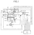
- An intake passage 11 and an exhaust passage 12 are communicated respectively with an intake port 10A and an exhaust port 10F of an internal combustion engine (cylinder block) 10.
- An intake temperature sensor 13 is mounted to the intake passage 11. Also, an airflow sensor 14 is mounted to the intake passage 11 downstream of the intake temperature sensor 13.
- a throttle valve 15 is disposed downstream of the airflow sensor 14.
- the throttle valve 15 is an electronically controlled throttle valve capable of controlling a throttle opening independent of the amount of depression of an accelerator.
- a surge tank 16 is communicated with the intake passage 11 at a position downstream of the throttle valve 15.
- An intake-pipe inner pressure sensor 17 is mounted to the surge tank 16.
- a fuel injection valve 18 for injecting fuel toward the intake port 10A is disposed downstream of the surge tank 16.
- the internal combustion engine 10 includes an intake valve 19 with a variably setting valve mechanism for making the valve opening phase (timing) variable.
- the intake valve 19 serves to open and close the intake port 10A, and a cam angle sensor 20 for detecting the valve opening phase is mounted to the variably setting valve mechanism of the intake valve 19.
- the internal combustion engine 10 includes a piston 10C being able to reciprocally move in a cylinder bore 10B, and a combustion chamber 22 is defined between the piston 10C and a cylinder head 10D.
- a spark plug 23 is mounted to the cylinder head 10D such that an electrode portion 23A of the spark plug 23 is exposed to the combustion chamber 22.
- a knock sensor 24 for detecting the occurrence of knock is mounted to the internal combustion engine 10.
- a crank angle sensor 25 is mounted to a crankshaft 10E.
- the exhaust port 10F of the internal combustion engine 10 is opened and closed by an exhaust valve 21.
- An A/F sensor 26 is mounted in the exhaust passage 12.
- an EGR pipe 27 for returning exhaust gas from the exhaust passage 12 to the intake passage 11 is connected to the exhaust passage 12.
- An EGR valve 28 for adjusting an EGR rate is disposed in a passage of the EGR pipe 27.
- the spark advance controller of this embodiment includes an ECU (Electronic Control Unit) 29.
- ECU Electronic Control Unit
- the above-mentioned various sensors are connected to the ECU 29.
- Various actuators such as the throttle valve 15, the fuel injection valve 18, the intake valve 19 with the variably setting valve mechanism, and the EGR valve 28, are controlled by the ECU 29. Also, the operating state of the internal combustion engine 10 is detected based on signals inputted from the above-mentioned various sensors, and the spark plug 23 is ignited at the ignition timing (spark advance) that has been decided by the ECU 29 depending on the operating state.
- a spark advance control logic producing section 50 comprises a numerical simulator 51, a map producing unit 52, and a regression model producing unit 53.
- the numerical simulator 51 In the production of the spark advance control logic, the numerical simulator 51 first computes the pressure and temperature in the cylinder of the internal combustion engine to be controlled. In this computing process, engine operating conditions, various engine dimensions, and physical models for determining physical phenomena occurred in the cylinder are taken into consideration. The computing process executed in the numerical simulator 51 will be described in detail later with reference to Fig. 3.
- the map producing unit 52 produces an MBT map and a knock retard map by obtaining the MBT and the knock limit under various operating conditions based on the relationships between the cylinder volume and the pressure and temperature in the cylinder, which have been determined by the numerical simulator 51.
- the regression model producing unit 53 approximates the thus-formed MBT map and the knock retard map by producing respective regression models.
- regression model means a plural and multi-degree polynominal in which map data is a dependent variable and a plurality of axes constituting a map are independent variables. Each term in the plural and multi-degree polynominal is multiplied by a partial regression coefficient. The partial regression coefficient indicates the degree of influence upon the dependent variable of each term in the regression model.
- a plural and multi-degree polynominal most closely approximating the map data is selected taking into account a change rate of the map data for each independent variable.
- the partial regression coefficient by which each term is multiplied is decided by the least square method to be a value that most closely approximates the map data.
- the regression model and the partial regression coefficient decided by the spark advance control logic producing section 50 are stored in a spark advance computing section 60 with respect to the MBT and the nock retard.
- the spark advance control logic producing section 50 is practically constituted by the ECU 29.
- the ECU 29 detects the engine operating state based on not only signals from the various sensors, but also signals for driving the various actuators, those signals being sensed during the vehicle operation. The following variables are taken into consideration in detecting the operating conditions.
- the engine speed is detected based on a pulse signal outputted from the crank angle sensor 25 per unit time.
- the engine load can be determined by detecting the pressure in the intake pipe.
- a manner of detecting the engine load is not limited to the above-mentioned one of detecting the pressure in the intake pipe, and the engine load may be determined based on a signal indicating one of the intake air amount, the charging efficiency, the air/fuel ratio, and the opening of the throttle valve per cycle.
- a torque sensor may be mounted on an axle to directly detect generated torque.
- characteristic values in operation of the intake valve include the valve opening timing of the intake valve, the overlap period between the intake valve opening timing and the exhaust valve opening timing, etc.
- the intake temperature can be detected by the intake temperature sensor 13.
- the equivalence ratio can be obtained based on a fuel injection valve drive signal generated by the ECU, the intake air amount detected by the airflow sensor 14, and the engine speed.
- the external EGR rate can be estimated by detecting the opening angle of the EGR valve 28, the engine speed, and the pressure in the intake pipe.
- a sensor for detecting a flow rate may be disposed in the EGR pipe 27 to directly detect the EGR rate.
- the above-mentioned operating conditions such as the engine speed, the load, the characteristic values in operation of the intake valve, the intake temperature, the equivalence ratio, and the external EGR rate, are inputted to the spark advance computing section 60 in the ECU.
- the spark advance computing section 60 includes an MBT reference function for computing an MBT reference value, an MBT modification function for computing an MBT modification value, a knock retard reference function for computing a knock retard reference value, and a knock retard modification function for computing a knock retard modification value.
- the spark advance computing section 60 successively computes the MBT reference value, the MBT modification value, the knock retard reference value, and the knock retard modification value by using the respective functions, and then outputs the spark advance corresponding to the engine operating conditions.
- the ECU 29 is required to neither include the data map for the spark advance therein, nor to compute physical models having a large computation load.
- the memory capacity of the ECU 29 can be reduced in comparison with that required in the case of a map search, and the computation load of the ECU 29 can also be reduced in comparison with that required in the case of directly computing the physical models.
- step 101 the engine operating conditions are inputted (set).
- the engine operating conditions include the engine speed, the pressure in the intake pipe, the characteristic in operation of the intake valve, the intake temperature, the equivalence ratio, the external EGR rate, the wall surface temperature, etc.
- the various engine dimensions include the bore, the stroke, the compression ratio, the shape of the combustion chamber, etc.
- the profile dimensions of the intake and exhaust valves, the valve opening characteristics of those valves, etc. are also set.
- the inner diameters and pipe lengths of the intake and exhaust valves are further set.
- Changes of the pressure and temperature in the cylinder are computed by executing computing steps 103 to 108, described below, per unit crank angle in a repeated manner under the above-described conditions.
- step 103 the numerical simulator 51 computes a cylinder volume change rate depending on a piston motion.
- the cylinder volume is determined taking into account at least the crank angle, the bore, the stroke, the compression ratio, and the ratio of the connecting rod length to the crank radius.
- step 104 the numerical simulator 51 computes a change rate of gas mass in the cylinder during the gas exchange process. In step 104, it is first determined based on the crank angle whether the engine is in the gas exchange (intake or exhaust) process.
- the mass of gas flowing into and out through the opening of each valve is obtained from the opening area of each valve and the relationship of the pressure in the intake pipe and the pressure in the exhaust pipe versus the pressure in the cylinder (cylinder pressure).
- the computed flow rate of the gas passing through the intake valve is not limited to the flow rate of the gas flowing forward, i.e., in the direction from the intake valve toward the cylinder.
- the cylinder pressure may exceed the pressure in the intake pipe. Even in such a case, the intake flow rate can be accurately computed in consideration of a backward gas flow toward the intake valve from the cylinder as well.
- step 104 for the mass of the gas passing through the intake valve and the mass of the gas passing through the exhaust valve in the gas exchange process will be described in more detail below with reference to Figs. 4A-4D.
- Fig. 4A shows a cumulative value of the gas mass passing through the intake valve, a cumulative value of the gas mass passing through the exhaust valve, and the total gas mass in the cylinder.
- Fig. 4B shows lift changes of the intake and exhaust valves, which provide the characteristics shown in Fig. 4A.
- the valve opening phase of the intake valve 19 is advanced depending on the operating conditions to set an overlap period between the valve opening period of the intake valve 19 and the valve opening period of the exhaust valve 21.
- a spit-back of burnt gas into the intake pipe is caused so as to suck the bunt gas again into the cylinder, thereby increasing a proportion of the burnt gas in the cylinder.
- Figs. 4C and 4D show respectively changes of the gas mass and the lift, by way of example, when the valve opening phase of the intake valve 19 is advanced from that in Figs. 4A and 4B to set the overlap period.
- change of an internal EGR rate resulting when the variably setting valve mechanism of the intake valve is operated can be accurately computed in consideration of the spit-back of the burnt gas in the overlap period as well.
- step 105 the numerical simulator 51 computes a rate of heat release with burning.
- Figs. 5A and 5B show respectively the rate of heat release after spark ignition and change of a burning mass proportion for explaining the burning process of the internal combustion engine.
- the burning in the internal combustion engine generates no appreciable heat during a period immediately after the spark ignition in terms of the crank angle ranging from 1 to 10°. Such a period is called an ignition delay period.
- the length of the ignition delay period depends on the temperature and pressure in the combustion chamber, the gas flow characteristic and gas composition near the spark plug, and spark energy.
- a flame kernel is formed in the electrode portion during the ignition delay period. After the lapse of the ignition delay period, a flame propagates over the whole of the combustion chamber. Most of the amount of heat to be generated from the gas mixture supplied to the cylinder heat is generated at that time. This subsequent period is called a main burning period. During the main burning period, a profile of the rate of heat release is dominated by the laminar burning velocity and the amount of the generated heat based on the gas flow characteristic and gas composition in the combustion chamber, the density of the not-burnt gas, and the flame surface area depending on the shape of the combustion chamber and the burning mass proportion.
- the step of computing the rate of heat release with the burning computes respective rates of heat release during those period separately from each other. As a result, the total rate of heat release in the internal combustion engine can be accurately computed even under the different operation conditions.
- the equivalence ratio of the gas mixture, the external EGR rate, and the internal EGR rate that is determined in consideration of the spit-back are inputted.
- dominant factors of the ignition delay period i.e., the temperature and pressure in the combustion chamber, the gas flow characteristic and gas composition near the spark plug, and the spark energy supplied from the spark plug to the not-burnt gas mixture, are inputted. Those variables are all values at the ignition timing.
- the turbulence intensity can be given as being substantially proportional to the average piston speed that is determined depending on the engine speed and the stroke.
- the turbulence scale can be given as being proportional to the clearance of the combustion chamber at the ignition timing.
- the ignition delay period in terms of the crank angle tends to increase on both the leaner side and the richer side with respect to the equivalence ratio of 1, and also to increase as the EGR rate increases.
- the ignition delay period decreases as the pressure and temperature of the non-burnt gas mixture at the ignition timing increases.
- the ignition delay period tends to decrease.
- the ignition delay period decreases.
- the spark energy is estimated from the battery voltage and the time during which current is supplied to a primary coil of an ignition coil. Also, as a more vigorous flow is generated near the electrode portion of the spark plug with the engine speed increasing, a proportion of energy which is lost to ambient gas from the energy supplied from the spark plug to the flame kernel increases, and therefore the ignition delay period tends to increase.
- burning mass proportion means a proportion of the mass of the burnt gas with respect to the total gas mass supplied to the cylinder, and is given as a parameter being 0 at the start of burning and 1 at the end of burning.
- the density of the not-burnt gas, the turbulence intensity, and the laminar burning velocity are computed.
- the temperature, pressure and composition of the not-burnt gas are taken into consideration in the step of computing the laminar burning velocity.
- the laminar burning velocity tends to increase as the temperature of the not-burnt gas increases and the pressure of the not-burnt gas lowers. Further, the laminar burning velocity tends to decrease as the EGR rate increases, and also tends to decrease on both the leaner side and the richer side with respect to the equivalence ratio of about 1.
- the main burning period can be accurately predicted taking into account change of the gas composition.
- the turbulent burning velocity is computed in consideration of an influence of the turbulence intensity.
- the turbulent burning velocity can be obtained as the product of the laminar burning velocity, the turbulence intensity, and the experiential constant of the turbulence burning velocity.
- the turbulence intensity is usually regarded to be proportional to the average piston speed.
- a swirl and/or a tumble is intentionally formed in the gas flow inside the combustion chamber to intensify the turbulence in the cylinder.
- a ratio of the turbulence intensity to the average piston speed is modified. From the viewpoint of computation, a change amount of the ratio of the turbulence intensity to the average piston speed is handled as being equivalent to a change amount of the experiential constant of the turbulence burning velocity.
- the experiential constant of the turbulence burning velocity is set to an optimum value based on data obtained using an actual engine in advance.
- the flame surface area is increased because a flame spreads over the whole of the combustion chamber as the burning progresses. However, the flame soon reaches the piston wall surface or the cylinder wall surface, whereby the flame propagation is blocked and the flame surface area is then reduced.
- Such change of the flame surface area greatly affects the profile of the rate of heat release during the main burning period.
- the flame surface area is obtained by, on an assumption that the flame propagates substantially in the spherical form from the spark plug, deciding a flame position at which the volume proportion of the burnt gas is satisfied, and computing the area based on the decided frame position and the shape of the combustion chamber. With that computing process, the change of the flame surface area can be accurately computed in consideration of the shape of the combustion chamber and the position of the spark plug as well, which differ depending on internal combustion engines.
- the rate of heat release with the burning is computed by using the density of the not-burnt gas, the amount of heat generated by the not-burnt gas, the turbulence burning velocity, and the flame surface area, which have been obtained by the above-described procedures.
- the rate of heat release with the burning tends to increase when any of the density of the not-burnt gas, the amount of heat generated by the not-burnt gas, the turbulence burning velocity, and the flame surface area increases.
- This computing process enables the change of the rate of heat release during the main burning period to be accurately computed in consideration of the shape of the combustion chamber and the operating conditions of the internal combustion engine as well.
- step 106 the numerical simulator 51 computes a heat loss through wall surfaces.
- the wall surface temperature is first inputted.
- the area of the wall surfaces of the combustion chamber surrounded by the cylinder and the piston is computed depending on the crank angle.
- the amount of heat transferred between the gas in the cylinder and the wall surfaces is greatly affected by the gas flow in the cylinder.
- the average piston speed is computed which depends on the engine speed and the stroke.
- a heat transfer rate to the wall surfaces is computed in consideration of the average piston speed and the pressure and temperature in the cylinder.
- the heat transfer rate to the wall surfaces per unit time tends to increase as the average piston speed increases.
- the heat loss through the wall surfaces is computed in consideration of the heat transfer rate to the wall surfaces, the surface area of the combustion chamber, and the wall surface temperature.
- the amount of heat transferred between the gas in the cylinder and the wall surface is increased as the difference between the gas temperature in the combustion chamber and the wall surface temperature increases.
- the cylinder pressure can be accurately computed in consideration of the heat loss through the wall surfaces as well, which is changed depending on spark advances set different from each other.
- the changes of the pressure and temperature in the cylinder can be accurately computed in step 107 based on the above-described variables, i.e., the change rate of the cylinder volume, the change rate of the gas mass in the cylinder during the gas exchange process, the rate of heat release with the burning, and the heat loss through the wall surfaces.
- step 108 the numerical simulator 51 computes a knock reaction progress variable. Details of manners for computing the knock reaction progress variable and detecting the occurrence of knock will be described below with reference to Figs. 6A and 6B. Each of Figs. 6A and 6B shows two typical examples in one of which knock occurs and in the other of which knock does not occur.
- a solid line represents change of the temperature of the not-burnt gas until the end of burning when the ignition timing is set to the MBT.
- a solid line represents change of the knock reaction progress variable until the end of burning when the ignition timing is set to the MBT.
- the occurrence of knock is determined depending on whether the knock reaction progress variable reaches a knock occurrence limit value until the end of burning.
- the knock reaction progress variable reaches the knock occurrence limit value until the end of burning as indicated by the solid line in Fig. 6B, it is determined that knock occurs. Then, in such a case, a process of computing a knock limit spark advance is executed.
- a broken line represents change of the temperature of the not-burnt gas until the end of burning when the ignition timing is retarded from the MBT to the knock limit spark advance.
- a broken line represents change of the knock reaction progress variable until the end of burning corresponding to the change of the temperature of the not-burnt gas represented by the broken line in Fig. 6A.
- the knock reaction progress variable does not reach the knock occurrence limit value until the end of burning. In this case, the retarding process is brought to an end at once and the ignition timing is set to the knock limit spark advance.
- knock reaction progress variable means a value resulting from integrating a reciprocal number of the reaction time, which is computed in consideration of the cylinder pressure, the temperature of the not-burnt gas, the octane number of fuel, and the experiential constant of knock sensitivity, over a time from the start of compression of the not-burnt gas.
- the reaction time tends to shorten as the pressure increases, as the temperature of the not-burnt gas rises, and as the octane number of fuel decreases.
- an increasing rate of the knock reaction progress variable increases and the knock is more apt to occur.
- the knock is more apt to occur when a compression time of the not-burnt gas is prolonged by reducing the engine speed or advancing the ignition timing.
- control variables are first set in step 111.
- the valve opening phase of the intake valve, the intake temperature, the equivalence ratio, and the external EGR rate are selected as factors affecting the MBT or the knock retard.
- maximum and minimum values in an allowable range of each control variable and typical points within the allowable range are set.
- the maximum and minimum values which can be taken by each control variable are selected so as to include all the operating conditions that are supposed in the internal combustion engine 10. Further, the number of typical points is decided depending on the accuracy demanded for control of the ignition timing.
- the cylinder pressure is computed in step 112.
- the computation of the cylinder pressure is preferably performed at intervals within 1 degree of the crank angle so as to obtain the cylinder pressure in each of the intake/exhaust stroke, the compression stroke, the burning stroke, and the expansion stroke.
- step 113 the indicated torque is computed based on the relationship between the computed cylinder pressure and the cylinder volume.
- Fig. 8A shows the relationship between the cylinder volume and the cylinder pressure at three different ignition timings 1, 2 and 3.
- the area within an enclosed curve obtained from the pressure versus volume relationship in the cylinder corresponds to the indicated torque that can be applied to the exterior from the internal combustion engine 10 per cycle.
- An enclosed curve appearing in the intake/exhaust stroke represents negative work, i.e., a pump loss.
- the indicated torque generated by the internal combustion engine equipped with the variably setting intake valve mechanism can be accurately computed in consideration of change of the pump loss as well, which is resulted when the valve opening phase of the intake valve 19 is made variable.
- the relationship between the ignition timing and the indicated torque is obtained by executing the above-described computation of the indicated torque for all of the selected typical ignition timings.
- step 114 the map producing unit 52 computes the MBT.
- the relationship between the ignition timing and the indicated torque, shown in Fig. 8B, is obtained by setting the typical ignition timings to a plurality of points and computing the corresponding torque.
- the relationship between the ignition timing and the indicated torque is changed depending on not only the shape of the internal combustion engine, but also the operating conditions of the internal combustion engine. By setting the typical ignition timings between 60 degree before the compression top dead center (TDC) and the compression top dead center, however, one peak P generally appears in the relationship between the ignition timing and the indicated torque.
- the ignition timing indicating the maximum indicated torque is then selected as the MBT by using the relationship between the ignition timing and the indicated torque.
- the MBT may be obtained by approximating the relationship between the ignition timing and the indicated torque, which has been obtained for each of at least three points, with a curve having second or higher order, and by setting a maximum value of the curve to the MBT.
- the number of points for the typical ignition timings and the number of orders of the approximation curve are decided depending on the demanded MBT accuracy.
- the MBT accuracy tends to increase as the number of points for the typical ignition timings and the number of orders of the approximation curve increase.
- the indicated torque available in the internal combustion engine 10 when the ignition timing is set to the MBT can also be computed at the same time as the computation of the MBT with high accuracy.
- steps 112-114 constitute an MBT map computing section 52A.
- step 115 it is determined whether knock occurs when the ignition timing is set to the MBT that has been obtained in step 114. If knock occurs, a knock retard is computed in step 116 through similar procedures to those used for computing the knock reaction progress variable (i.e., step 108 in Fig. 3) in the numerical simulation 51.
- Those steps 115 and 116 constitute a knock retard map computing section 52B.
- Respective map data of the MBT and the knock retard are produced by executing the above-described steps for each of the typical points set for all the control variables.
- the MBT map and the knock retard map are separately produced as maps for controlling the ignition timing (spark advance), and a regression model is produced for each of those maps.
- a regression model is produced for each of those maps.
- both the MBT and the knock retard are computed and the ignition timing is given as the sum of the computed MBT and knock retard.
- the MBT is greatly affected by the turbulence intensity, while the knock is a phenomenon that is substantially decided depending on the temperature history of the gas in the cylinder.
- the map data can be more accurately approximated by producing the MBT map and the knock retard map separately from each other, and by approximating each of those maps with a regression model.
- the regression models are produced for two kinds of map data, i.e., the MBT map data and the knock retard map data.
- a dependent variable y represents the MBT
- x1, x2 and x3 are independent variables constituting the MBT map data.
- A0 to A19 are partial regression coefficients representing the degrees of influences of respective terms upon y.
- the above triple and third-degree polynominal is constituted as follows.
- A0 provides a value of y when all values of x1, x2 and x3 are 0.
- A1 to A3 are terms including only x1.
- A4 to A6 are terms including only x2.
- A7 to A9 are interaction terms including x1 and x2.
- A10 to A12 are terms including only x3.
- A13 to A19 are interaction terms including at least x3 combined with x1 or x2.
- x1 represents the engine speed
- x2 represents the load
- x3 represents one of the intake valve opening timing, the intake temperature, the equivalence ratio, and the external EGR rate.
- a two-dimensional map curved surface and the above plural and multi-degree polynominal will be described below with reference to Figs. 10A and 10B.
- y decreases as x1 increases, and a change rate of y is not affected by a level of x2.
- an influence upon y can be expressed by the sum of a polynominal including only x1 and a polynominal including only x2.
- an interaction term expressed by the product of x1 and x2 has to be considered in the regression model in addition to a polynominal including only x1 and a polynominal including only x2. That relationship between the map data and the regression model holds even when the variables x1, x2 and x3 are replaced with one another.
- the MBT is largely changed with respect to the engine speed and the load.
- the reason is that noted correlation exists between the MBT and the burning velocity, and the burning velocity is greatly affected by the pressure and temperature in the cylinder and the turbulence intensity.
- the interaction term including x1 and x2 has to be taken into consideration.
- the knock retard map usually has values only in a region of high loads and low engine speeds, and shows 0 in the other regions.
- the interaction term including the engine speed x1 and the load x2 has to be considered in the regression model in addition to the term including only the engine speed x1 and the term including only the load x2.
- the reference function is given as a function expressed by the term including only x1, the term including only x2, the interaction term including x1 and x2, as well as A0.
- the MBT reference value can be accurately computed regardless of changes in the conditions of the engine speed and the load.
- step 122 an MBT reference function is produced from the MBT regression model that has been produced in step 121.
- an MBT modification function is produced.
- the MBT modification function is a polynominal made up of the terms in the formula (1), which are multiplied by the partial regression coefficients A10 to A19.
- a modification variable x3 represents one of the intake valve opening timing, the intake temperature, the equivalence ratio, and the external EGR rate.
- the intake valve opening timing is advanced to set an overlap period between the intake period and the exhaust period such that the burnt gas in the cylinder is caused to flow back toward the intake pipe for supply into the intake pipe again.
- the MBT modification function is produced as follows.
- the MBT usually tends to advance as the intake valve opening timing is advanced to increase the overlap period.
- an interaction term including the engine speed x1 and the intake valve opening timing x3 has to be taken into consideration in order to accurately approximate the influence of the intake valve opening timing upon the MBT by using the regression model.
- the influence of the overlap period upon the MBT also differs depending on the pressure in the intake pipe, i.e., a level of the load.
- an interaction term including the load x2 and the intake valve opening timing x3 has to be taken into consideration in order to accurately approximate the influence of the intake valve opening timing upon the MBT by using the regression model.
- the modification function is given as a function expressed by the term including only x3, the interaction term including x3 and x1, and the interaction term including x3 and x2.
- the MBT modification value can be accurately computed even when the modification variable are changed in various ways.
- an MBT modification function is produced from the MBT regression model that has been produced in step 121.
- the MBT modification function is similarly produced for each of the intake temperature, the equivalence ratio, and the EGR rate in addition to the intake valve opening timing.
- the knock retard map is approximated with a regression model in steps 124 to 126.
- a process of producing the regression model, a process of producing a knock retard reference function, and a process of producing a knock retard modification function are the same as those for the MBT. (Computation of Spark Advance)
- a spark advance computing process executed by the spark advance computing section 60 in the ECU 29 will be described in detail with reference to Fig. 11.
- the spark advance computing section 60 in the ECU 29 comprises an MBT computing section 60A and a knock retard computing section 60B.
- the MBT computing section 60A stores the reference function for the MBT and the respective modification functions for the various modification variables
- the knock retard computing section 60B stores the reference function for the knock retard and the respective modification functions for the various modification variables.
- the operating conditions such as the engine speed, the load, the characteristic values in operation of the intake valve, the intake temperature, the equivalence ratio, and the EGR rate, are inputted to both the computing sections 60A and 60B.
- the functions stored in the MBT computing section 60A and the knock retard computing section 60B include the MBT reference function, the MBT modification functions, the knock retard reference function, and the knock retard modification functions which have been produced by the regression model producing unit 53 (in steps 121 to 126 in Fig. 9), as well as the partial regression coefficients contained in those functions.
- the MBT and the knock retard are each given as the total sum of respective modification values determined for the modification variables. This means that influences of the interaction terms representing the interactions between the modification variables are ignored. In other words, looking at the terms including two variables, the following interaction terms are omitted: ( intake valve opening timing ⁇ intake temperature ) , ( intake valve opening timing ⁇ equivalence ratio ) , ( intake valve opening timing ⁇ external EGR ratio ) , ( intake temperature ⁇ equivalence ratio ) , ( intake temperature ⁇ external EGR rate ) , and ( equivalence ratio ⁇ external EGR rate )
- Fig. 12 is a graph showing the relationship between the equivalence ratio and the laminar burning velocity under different conditions of the EGR rate (i.e., with EGR and without EGR).
- the laminar burning velocity is one of the most important affecting factors in the process of deciding the MBT.
- the laminar burning velocity takes a maximum value under the condition of the equivalence ratio being slightly richer than 1.0, and it reduces in either side richer or leaner than such an equivalence ratio.
- the laminar burning velocity tends to reduce at any value of the equivalence ratio.
- the MBT modification value used when the intake valve opening timing is advanced can be substantially explained based on the proportion of the burnt gas supplied to the' cylinder. This is similarly applied to the relationship between the intake valve opening timing and the equivalence ratio or between the intake valve opening timing and the external EGR rate.
- total MBT modification value ⁇ y ( x 1 , x 2 , intake valve opening timing ) + ⁇ y ( x 1 , x 2 , intake temperature ) + ⁇ y ( x 1 , x 2 , equivalence ratio ) + ⁇ y ( x 1 , x 2 , external EGR rate )
- the computation load can be cut without reducing the accuracy in the MBT computing process.
- the above-described manner is similarly applied to the process of computing the knock retard map.
- the polynominal constituting the regression model is not limited to that one.
- the accuracy in approximation of the map data is improved by increasing the number of degrees of the regression model. Therefore, a regression model with higher degrees may be prepared, and all the interaction terms representing the interactions between the modification variables may be taken into consideration.
- the higher degree and the increased number of the interaction terms increase the computation load. For that reason, the number of degrees and the number of the interaction terms are decided depending on the demanded accuracy in computation of the spark advance.
- the partial regression coefficient by which the term in the regression model is multiplied represents the degree of influence of the relevant term upon the dependent variable.
- the independent variables x1, x2 and x3 have different dimensions from one another. By normalizing a range of allowable value of each independent variable and setting it as a parameter having a value of, e.g., from -1 to +1, therefore, the magnitudes of the partial regression coefficients obtained with such normalization can be evaluated on the equivalent basis as contribution rates to the respective terms.
- a regression model having the number of computing steps cut to fall within a range satisfying the demanded accuracy in computation can be decided in a trial-and-error way by repeating steps of computing the partial regression coefficients with the regression model in the form of a polynominal having sufficiently high degree in advance, and omitting the term with a smaller contribution rate based on the computed magnitudes of the partial regression coefficients.
- the present invention is not limited to that mode.
- the map data can be approximated with higher accuracy by subdividing the map data for each of operating ranges and producing a regression model per subdivided group of the map data.
- the present invention is not limited to that setting.
- the present invention can be applied to all control parameters affecting the temperature, pressure, composition, and flow of the gas in the cylinder, such as the cooling water temperature and the opening of a tumble control valve, without substantially modifying the above-described embodiment.
Landscapes
- Engineering & Computer Science (AREA)
- Theoretical Computer Science (AREA)
- Signal Processing (AREA)
- Chemical & Material Sciences (AREA)
- Combustion & Propulsion (AREA)
- Mechanical Engineering (AREA)
- General Engineering & Computer Science (AREA)
- Combined Controls Of Internal Combustion Engines (AREA)
- Electrical Control Of Ignition Timing (AREA)
- Output Control And Ontrol Of Special Type Engine (AREA)
Applications Claiming Priority (1)
| Application Number | Priority Date | Filing Date | Title |
|---|---|---|---|
| JP2005011106A JP4376799B2 (ja) | 2005-01-19 | 2005-01-19 | 内燃機関の点火時期制御装置 |
Publications (3)
| Publication Number | Publication Date |
|---|---|
| EP1683963A2 true EP1683963A2 (fr) | 2006-07-26 |
| EP1683963A3 EP1683963A3 (fr) | 2007-01-03 |
| EP1683963B1 EP1683963B1 (fr) | 2009-06-17 |
Family
ID=36202426
Family Applications (1)
| Application Number | Title | Priority Date | Filing Date |
|---|---|---|---|
| EP06001104A Expired - Fee Related EP1683963B1 (fr) | 2005-01-19 | 2006-01-19 | Contrôleur d'avance à l'allumage et dispositif de génération de la logique de commande d'avance à l'allumage pour un moteur à combustion interne |
Country Status (4)
| Country | Link |
|---|---|
| US (1) | US7290529B2 (fr) |
| EP (1) | EP1683963B1 (fr) |
| JP (1) | JP4376799B2 (fr) |
| DE (1) | DE602006007246D1 (fr) |
Cited By (2)
| Publication number | Priority date | Publication date | Assignee | Title |
|---|---|---|---|---|
| EP2012000A1 (fr) * | 2007-07-05 | 2009-01-07 | MAGNETI MARELLI POWERTRAIN S.p.A. | Procédé de commande pour l'avance à l'allumage pour un cylindre de moteur à combustion interne |
| FR2943100A1 (fr) * | 2009-03-16 | 2010-09-17 | Peugeot Citroen Automobiles Sa | Procede de determination de l'avance a l'allumage d'un moteur thermique |
Families Citing this family (30)
| Publication number | Priority date | Publication date | Assignee | Title |
|---|---|---|---|---|
| US8606544B2 (en) * | 2006-07-25 | 2013-12-10 | Fisher-Rosemount Systems, Inc. | Methods and systems for detecting deviation of a process variable from expected values |
| US7912676B2 (en) | 2006-07-25 | 2011-03-22 | Fisher-Rosemount Systems, Inc. | Method and system for detecting abnormal operation in a process plant |
| US7657399B2 (en) | 2006-07-25 | 2010-02-02 | Fisher-Rosemount Systems, Inc. | Methods and systems for detecting deviation of a process variable from expected values |
| US8145358B2 (en) | 2006-07-25 | 2012-03-27 | Fisher-Rosemount Systems, Inc. | Method and system for detecting abnormal operation of a level regulatory control loop |
| WO2008040018A2 (fr) | 2006-09-28 | 2008-04-03 | Fisher-Rosemount Systems, Inc. | Prévention d'une situation anormale dans un échangeur thermique |
| DE102006056708B4 (de) * | 2006-11-30 | 2012-03-08 | Robert Bosch Gmbh | Verfahren, Vorrichtung und Computerprogramm zur Bestimmung zylinderindividueller Verbrennugsmerkmale einer Brennkraftmaschine |
| US8032341B2 (en) | 2007-01-04 | 2011-10-04 | Fisher-Rosemount Systems, Inc. | Modeling a process using a composite model comprising a plurality of regression models |
| US8032340B2 (en) * | 2007-01-04 | 2011-10-04 | Fisher-Rosemount Systems, Inc. | Method and system for modeling a process variable in a process plant |
| US7827006B2 (en) | 2007-01-31 | 2010-11-02 | Fisher-Rosemount Systems, Inc. | Heat exchanger fouling detection |
| JP4882787B2 (ja) | 2007-02-19 | 2012-02-22 | トヨタ自動車株式会社 | 内燃機関の制御装置 |
| JP4760733B2 (ja) * | 2007-02-22 | 2011-08-31 | トヨタ自動車株式会社 | 内燃機関の制御システム |
| JP4835483B2 (ja) * | 2007-03-23 | 2011-12-14 | トヨタ自動車株式会社 | 予測装置、制御装置及び予測プログラム |
| US8301676B2 (en) | 2007-08-23 | 2012-10-30 | Fisher-Rosemount Systems, Inc. | Field device with capability of calculating digital filter coefficients |
| US7702401B2 (en) | 2007-09-05 | 2010-04-20 | Fisher-Rosemount Systems, Inc. | System for preserving and displaying process control data associated with an abnormal situation |
| US8055479B2 (en) | 2007-10-10 | 2011-11-08 | Fisher-Rosemount Systems, Inc. | Simplified algorithm for abnormal situation prevention in load following applications including plugged line diagnostics in a dynamic process |
| JP2009150345A (ja) * | 2007-12-21 | 2009-07-09 | Hitachi Ltd | 内燃機関の制御装置 |
| JP4969546B2 (ja) * | 2008-09-30 | 2012-07-04 | 日立オートモティブシステムズ株式会社 | 内燃機関の制御装置および方法 |
| JP5113126B2 (ja) * | 2009-06-30 | 2013-01-09 | 日立オートモティブシステムズ株式会社 | 内燃機関の制御装置 |
| EP2474728B1 (fr) * | 2009-09-02 | 2015-05-06 | Toyota Jidosha Kabushiki Kaisha | Système de commande de recyclage des gaz d'échappement d'un moteur à combustion interne |
| JP5270008B2 (ja) * | 2009-12-18 | 2013-08-21 | 本田技研工業株式会社 | 内燃機関の制御装置 |
| WO2012093515A1 (fr) * | 2011-01-07 | 2012-07-12 | 本田技研工業株式会社 | Dispositif de commande de moteur à combustion interne |
| JP5870632B2 (ja) * | 2011-11-08 | 2016-03-01 | 富士通株式会社 | 情報処理装置 |
| JP2014202182A (ja) * | 2013-04-09 | 2014-10-27 | トヨタ自動車株式会社 | 内燃機関の熱発生率波形作成装置および燃焼状態診断装置 |
| DE102013206286A1 (de) * | 2013-04-10 | 2014-10-16 | Robert Bosch Gmbh | Verfahren und Vorrichtung zum Bestimmen eines Zündwinkels in einem Motorsteuergerät |
| JP6195545B2 (ja) * | 2014-07-08 | 2017-09-13 | 本田技研工業株式会社 | 内燃機関の制御装置 |
| EP3295006B1 (fr) * | 2015-05-14 | 2021-05-12 | The Regents of The University of Michigan | Modélisation prédictive et atténuation de ratés d'allumage dans des moteurs à explosion |
| KR102670373B1 (ko) | 2016-10-12 | 2024-05-28 | 삼성전자주식회사 | 반도체 소자 검사 장치 및 이를 포함하는 시스템 |
| JP6740157B2 (ja) * | 2017-03-13 | 2020-08-12 | 株式会社東芝 | 解析装置、解析方法、及び、プログラム |
| KR102165878B1 (ko) * | 2020-01-20 | 2020-10-14 | 주식회사 현대케피코 | 인공신경망을 이용한 차량 엔진 토크 추정 방법 |
| JP7431381B2 (ja) | 2021-04-19 | 2024-02-14 | 日立Astemo株式会社 | 内燃機関の制御装置 |
Citations (3)
| Publication number | Priority date | Publication date | Assignee | Title |
|---|---|---|---|---|
| JPH1030535A (ja) | 1996-07-12 | 1998-02-03 | Nissan Motor Co Ltd | エンジンの点火時期制御装置 |
| JP2003046758A (ja) | 2001-07-31 | 2003-02-14 | Canon Inc | 撮像装置、情報処理装置、画像処理装置およびその方法、並びに、画像処理システム |
| JP2004100495A (ja) | 2002-09-05 | 2004-04-02 | Toyota Motor Corp | 内燃機関の制御装置 |
Family Cites Families (11)
| Publication number | Priority date | Publication date | Assignee | Title |
|---|---|---|---|---|
| US4063538A (en) * | 1976-02-12 | 1977-12-20 | The Board Of Trustees Of Leland Stanford Junior University | Ignition timing control method and apparatus |
| US5099683A (en) * | 1990-05-22 | 1992-03-31 | Barrack Technology Limited | Method and apparatus for determining certain operating and running parameters in an internal combustion engine |
| DE4326949C2 (de) | 1993-08-11 | 1997-08-07 | Opel Adam Ag | Managementsystem für Kolbenbrennkraftmaschinen, insbesondere Ottomotoren von Kraftfahrzeugen |
| DE19549649B4 (de) | 1994-05-10 | 2004-06-17 | Mitsubishi Jidosha Kogyo K.K. | Steuer-Vorrichtung für einen Verbrennungsmotor mit einem Abgaskatalysator |
| US6236908B1 (en) * | 1997-05-07 | 2001-05-22 | Ford Global Technologies, Inc. | Virtual vehicle sensors based on neural networks trained using data generated by simulation models |
| US6553949B1 (en) * | 2001-03-05 | 2003-04-29 | Ford Global Technologies, Inc. | Engine knock prevention system and method |
| JP2003049758A (ja) | 2001-08-08 | 2003-02-21 | Toyota Motor Corp | 内燃機関の点火時期制御装置 |
| EP1416143A1 (fr) * | 2002-10-29 | 2004-05-06 | STMicroelectronics S.r.l. | Capteur virtuel pour des émissions d'un moteur à combustion interne et le système de commande d'injection |
| US7133761B2 (en) * | 2003-06-30 | 2006-11-07 | Westport Research Inc. | Method and apparatus for controlling an internal combustion engine using accelerometers |
| WO2005103640A2 (fr) * | 2004-04-20 | 2005-11-03 | Southwest Research Institute | Capteur de pression de cylindre virtuel equipe d'un dispositif d'estimation de valeurs de pression |
| US6970781B1 (en) * | 2004-06-03 | 2005-11-29 | Ford Global Technologies, Llc | Compression ratio mode selection logic for an internal combustion engine having discrete variable compression ratio control mechanism |
-
2005
- 2005-01-19 JP JP2005011106A patent/JP4376799B2/ja active Active
-
2006
- 2006-01-18 US US11/333,174 patent/US7290529B2/en active Active
- 2006-01-19 EP EP06001104A patent/EP1683963B1/fr not_active Expired - Fee Related
- 2006-01-19 DE DE602006007246T patent/DE602006007246D1/de active Active
Patent Citations (3)
| Publication number | Priority date | Publication date | Assignee | Title |
|---|---|---|---|---|
| JPH1030535A (ja) | 1996-07-12 | 1998-02-03 | Nissan Motor Co Ltd | エンジンの点火時期制御装置 |
| JP2003046758A (ja) | 2001-07-31 | 2003-02-14 | Canon Inc | 撮像装置、情報処理装置、画像処理装置およびその方法、並びに、画像処理システム |
| JP2004100495A (ja) | 2002-09-05 | 2004-04-02 | Toyota Motor Corp | 内燃機関の制御装置 |
Cited By (5)
| Publication number | Priority date | Publication date | Assignee | Title |
|---|---|---|---|---|
| EP2012000A1 (fr) * | 2007-07-05 | 2009-01-07 | MAGNETI MARELLI POWERTRAIN S.p.A. | Procédé de commande pour l'avance à l'allumage pour un cylindre de moteur à combustion interne |
| FR2943100A1 (fr) * | 2009-03-16 | 2010-09-17 | Peugeot Citroen Automobiles Sa | Procede de determination de l'avance a l'allumage d'un moteur thermique |
| WO2010106259A1 (fr) * | 2009-03-16 | 2010-09-23 | Peugeot Citroën Automobiles SA | Procede de determination de l'avance a l'allumage d'un moteur thermique |
| CN102428260A (zh) * | 2009-03-16 | 2012-04-25 | 标致·雪铁龙汽车公司 | 确定热力发动机点火提前量的方法 |
| CN102428260B (zh) * | 2009-03-16 | 2014-06-11 | 标致·雪铁龙汽车公司 | 确定热力发动机点火提前量的方法 |
Also Published As
| Publication number | Publication date |
|---|---|
| EP1683963A3 (fr) | 2007-01-03 |
| JP2006200396A (ja) | 2006-08-03 |
| DE602006007246D1 (de) | 2009-07-30 |
| US20060157029A1 (en) | 2006-07-20 |
| US7290529B2 (en) | 2007-11-06 |
| JP4376799B2 (ja) | 2009-12-02 |
| EP1683963B1 (fr) | 2009-06-17 |
Similar Documents
| Publication | Publication Date | Title |
|---|---|---|
| EP1683963B1 (fr) | Contrôleur d'avance à l'allumage et dispositif de génération de la logique de commande d'avance à l'allumage pour un moteur à combustion interne | |
| US7269495B2 (en) | Engine output calculation method and engine output calculation apparatus | |
| EP2123887B1 (fr) | Contrôle du combustible dans un moteur à combustion interne | |
| US20090132145A1 (en) | Method for the estimation of combustion parameters | |
| US7870844B2 (en) | Control system and method for internal combustion engine | |
| JP4447626B2 (ja) | 内燃機関の制御装置 | |
| US20050065707A1 (en) | Control device of internal combustion engine | |
| US6557526B1 (en) | Setting minimum spark advance for best torque in an internal combustion engine | |
| JP5674903B1 (ja) | 内燃機関の筒内圧推定装置 | |
| KR19980087252A (ko) | 엔진 내의 두 스파크 점화 연소 상태 사이의 순간 제어 시스템 | |
| CN104847519A (zh) | 用于平衡内燃发动机的气缸的方法 | |
| US9976534B2 (en) | Control device and control method for internal combustion engine | |
| EP2602461A1 (fr) | Dispositif de commande de moteur à combustion interne | |
| EP2843218B1 (fr) | Calcul de rapport air/carburant dans un moteur à combustion interne basé sur la position du moteur | |
| JP2007092616A (ja) | エンジンの点火時期制御方法及びエンジンの点火時期制御装置 | |
| US11629683B2 (en) | Internal combustion engine control device | |
| JP2008025406A (ja) | 内燃機関の制御装置 | |
| JP5113126B2 (ja) | 内燃機関の制御装置 | |
| JP2010216887A (ja) | エンジンシミュレータ | |
| JP2008075633A (ja) | 内燃機関の燃焼制御装置 | |
| JP2012219757A (ja) | 内燃機関の制御装置 | |
| JP4803099B2 (ja) | 可変圧縮比エンジンのトルク推定装置 | |
| EP2400133B1 (fr) | Appareil de contrôle de moteur | |
| JP4872383B2 (ja) | エンジンの点火時期制御方法及びエンジンの点火時期制御装置 | |
| JP4244654B2 (ja) | エンジンの点火時期制御装置 |
Legal Events
| Date | Code | Title | Description |
|---|---|---|---|
| PUAI | Public reference made under article 153(3) epc to a published international application that has entered the european phase |
Free format text: ORIGINAL CODE: 0009012 |
|
| AK | Designated contracting states |
Kind code of ref document: A2 Designated state(s): AT BE BG CH CY CZ DE DK EE ES FI FR GB GR HU IE IS IT LI LT LU LV MC NL PL PT RO SE SI SK TR |
|
| AX | Request for extension of the european patent |
Extension state: AL BA HR MK YU |
|
| PUAL | Search report despatched |
Free format text: ORIGINAL CODE: 0009013 |
|
| AK | Designated contracting states |
Kind code of ref document: A3 Designated state(s): AT BE BG CH CY CZ DE DK EE ES FI FR GB GR HU IE IS IT LI LT LU LV MC NL PL PT RO SE SI SK TR |
|
| AX | Request for extension of the european patent |
Extension state: AL BA HR MK YU |
|
| 17P | Request for examination filed |
Effective date: 20070703 |
|
| AKX | Designation fees paid |
Designated state(s): DE FR |
|
| 17Q | First examination report despatched |
Effective date: 20070820 |
|
| GRAP | Despatch of communication of intention to grant a patent |
Free format text: ORIGINAL CODE: EPIDOSNIGR1 |
|
| GRAS | Grant fee paid |
Free format text: ORIGINAL CODE: EPIDOSNIGR3 |
|
| GRAA | (expected) grant |
Free format text: ORIGINAL CODE: 0009210 |
|
| AK | Designated contracting states |
Kind code of ref document: B1 Designated state(s): DE FR |
|
| REF | Corresponds to: |
Ref document number: 602006007246 Country of ref document: DE Date of ref document: 20090730 Kind code of ref document: P |
|
| PLBE | No opposition filed within time limit |
Free format text: ORIGINAL CODE: 0009261 |
|
| STAA | Information on the status of an ep patent application or granted ep patent |
Free format text: STATUS: NO OPPOSITION FILED WITHIN TIME LIMIT |
|
| 26N | No opposition filed |
Effective date: 20100318 |
|
| REG | Reference to a national code |
Ref country code: FR Ref legal event code: ST Effective date: 20100930 |
|
| PG25 | Lapsed in a contracting state [announced via postgrant information from national office to epo] |
Ref country code: FR Free format text: LAPSE BECAUSE OF NON-PAYMENT OF DUE FEES Effective date: 20100201 |
|
| REG | Reference to a national code |
Ref country code: DE Ref legal event code: R081 Ref document number: 602006007246 Country of ref document: DE Owner name: HITACHI ASTEMO, LTD., HITACHINAKA-SHI, JP Free format text: FORMER OWNER: HITACHI AUTOMOTIVE SYSTEMS, LTD., HITACHINAKA-SHI, IBARAKI, JP Ref country code: DE Ref legal event code: R081 Ref document number: 602006007246 Country of ref document: DE Owner name: HITACHI ASTEMO, LTD., HITACHINAKA-SHI, JP Free format text: FORMER OWNER: HITACHI, LTD., TOKYO, JP |
|
| PGFP | Annual fee paid to national office [announced via postgrant information from national office to epo] |
Ref country code: DE Payment date: 20221130 Year of fee payment: 18 |
|
| REG | Reference to a national code |
Ref country code: DE Ref legal event code: R119 Ref document number: 602006007246 Country of ref document: DE |