EP1683633B1 - Gravure printing unit for printing on a web in a printing machine - Google Patents
Gravure printing unit for printing on a web in a printing machine Download PDFInfo
- Publication number
- EP1683633B1 EP1683633B1 EP06000705A EP06000705A EP1683633B1 EP 1683633 B1 EP1683633 B1 EP 1683633B1 EP 06000705 A EP06000705 A EP 06000705A EP 06000705 A EP06000705 A EP 06000705A EP 1683633 B1 EP1683633 B1 EP 1683633B1
- Authority
- EP
- European Patent Office
- Prior art keywords
- printing
- gravure
- cylinder
- printing unit
- fact
- Prior art date
- Legal status (The legal status is an assumption and is not a legal conclusion. Google has not performed a legal analysis and makes no representation as to the accuracy of the status listed.)
- Not-in-force
Links
Images


Classifications
-
- B—PERFORMING OPERATIONS; TRANSPORTING
- B41—PRINTING; LINING MACHINES; TYPEWRITERS; STAMPS
- B41F—PRINTING MACHINES OR PRESSES
- B41F9/00—Rotary intaglio printing presses
- B41F9/003—Web printing presses
-
- B—PERFORMING OPERATIONS; TRANSPORTING
- B41—PRINTING; LINING MACHINES; TYPEWRITERS; STAMPS
- B41F—PRINTING MACHINES OR PRESSES
- B41F13/00—Common details of rotary presses or machines
- B41F13/44—Arrangements to accommodate interchangeable cylinders of different sizes to enable machine to print on areas of different sizes
-
- B—PERFORMING OPERATIONS; TRANSPORTING
- B41—PRINTING; LINING MACHINES; TYPEWRITERS; STAMPS
- B41F—PRINTING MACHINES OR PRESSES
- B41F9/00—Rotary intaglio printing presses
- B41F9/02—Rotary intaglio printing presses for multicolour printing
- B41F9/023—Web printing presses
Definitions
- the invention relates to a gravure printing unit for printing a printing material web in a printing press, with at least one gravure printing cylinder, an inking device and a counter-pressure cylinder.
- printing machines for printing labels in particular self-adhesive labels
- a great deal of flexibility or variability is desired in order to be able to carry out as many different types of printing jobs as possible, in particular by producing special optical effects through the printed image or the printed text.
- printing machines which process a narrow web of a printing material and have a number of connection platforms or interfaces, on each of which a functional unit or a process module can be detachably received for printing with a specific printing method.
- a printing press is in the document US 4,384,522 described.
- the individual functional units can work with mutually different printing methods.
- Multi-printing presses are known in series construction which permit the detachable receipt of a number of functional units or process modules on a number of interconnect platforms.
- the functional units may contain, among other things, printing units or parts of printing units in cassettes or essays which operate according to a letterpress method, a flexographic printing method, a screen printing method, an offset printing method, a gravure printing method or an inkjet printing method.
- functional units processing units
- processing units are provided which allow mechanical processing steps on the printing material, for example, an embossing, a trimming (perforation, punching) or make a turn. such are also referred to as combination printing machines or hybrid printing machines, which are generic terms in this technical field.
- a commonly used configuration of a gravure printing unit such as is also used in the form of a functional unit for a printing press equipped with connection platforms, is, for example, in the document DE 42 42 582 C2 shown.
- the lateral surface of a gravure cylinder also referred to below as a printing cylinder simpler, at least partially immersed in an inkwell filled with inkwell, which is located below the gravure cylinder.
- the wells passing through the well in the lateral surface are filled with gravure ink. Excess paint is stripped off by at least one squeegee against the jacket surface.
- the gravure ink is transferred to a substrate, which is called by means of a counter-pressure cylinder, often referred to as impression roller, on the colored outer surface of the gravure printing cylinder.
- a gravure printing unit is designed as a process module, in particular in the form of an attachment or a cassette, for a printing press with connection platforms, then the practical disadvantage that should not be underestimated is that the printing material web has to be threaded along its path through the gravure printing unit in a web-processing printing press. In other words, the paths of the web through the printing press with and without gravure printing differ from each other.
- the change from a gravure printing unit to a printing unit that works with a different printing method or vice versa is therefore associated with a corresponding set-up time.
- a trial printing machine which has a replaceable press cylinder.
- a press cylinder mounted on movable carriage cylinder, optionally a gravure cylinder or a flexographic printing cylinder, which cooperates with a raster cylinder, are delivered.
- the interchangeable cylinders are driven by friction or by a positive gear connection from the press cylinder.
- EP 0 934 827 A2 discloses a printing unit, which can be converted between a direct and an indirect gravure printing process. While the counter-pressure cylinder remains in the printing unit, impression cylinder and transfer cylinder can be added detachably connectable in the side walls, wherein a releasable operative connection of the printing cylinder is closed by a direct drive by means of a clutch. Although the trajectory is maintained by the printing unit when changing a printing cylinder, the trajectory is changed during conversion between the two gravure printing process.
- EP 0 864 421 A1 is a printing machine with changeable inking devices with directly driven printing units in a horizontal arrangement (series construction) known.
- the pressure cylinders accommodated in bearing elements are also interchangeable, so that it is possible to change between different printing processes.
- the inking device can be turned off by horizontal displacement of the printing cylinder.
- inking unit and printing cylinder are assigned to a counter-pressure cylinder on a console displaceable and can be employed on the impression cylinder by means of separate spindle drives.
- the object of the present invention is to provide a gravure printing unit in a printing machine for printing on a printing material web, which allows rapid replacement by a printing unit, which operates on a different printing method.
- An intaglio printing unit for printing on a printing material web in a printing press, with a printing cylinder (used in this illustration as a short print for rotogravure cylinder), an inking device and a counter-pressure cylinder, has at least one connecting element for releasably receiving at least one in substantially horizontal direction movable connection platform Printing press and for producing a releasable operative connection with a separate drive for the one printing cylinder, so that the printing cylinder and the inking device are separable from the at least one connecting platform, wherein the impression cylinder remains in the printing press, that is, in other words, a pressure cylinder and the inking device are separable without separating the impression cylinder from the printing press.
- connection can preferably take place without changing the course of the printing substrate through the printing press and / or without severing the printing material web.
- there may be a first number, in particular a plurality, of connecting elements which serve only for detachable reception on at least one connecting platform of the printing press, and a second number, in particular one or a plurality, of connecting elements which are capable of detachable reception on at least one of them Connecting platform of the printing press as well as for the production of a releasable operative connection with a separate drive for the printing cylinder.
- the printing cylinder can be designed such that it can receive a gravure form, in particular in the form of a sleeve, or that its lateral surface forms an engraved gravure form.
- the gravure printing unit has at least two connecting elements, wherein at least one first connecting element for releasably receiving the printing cylinder on a first connection platform of the printing machine and at least one second connecting element for releasably receiving the inking device on a second connection platform of the printing machine is suitable or executed.
- both the printing cylinder and the inking device can be independently separated from the printing machine and attached to the printing press.
- the first and the second connection platform are movable relative to each other, in particular displaceable or pivotable. By a relative movement, in particular a lateral displacement, an adaptation to different gravure cylinder diameter (format dependent) is possible.
- the accessibility can be increased or decreased according to the various operations (printing, cleaning, setting up).
- the printing machine can be a series-produced printing machine, that is to say printing units arranged in the horizontal direction.
- the inking device may be a cooperating with the printing cylinder ink chamber doctor blade.
- the ink chamber doctor blade can be open, d. H. have a color cycle with a continuous flow of color through the ink chamber, or be closed.
- the ink chamber doctor blade can have a doctor blade, which is set at an acute angle with the direction of rotation of the lateral surface (negative doctor), so that it is possible to work with less pressure to set up the doctor blade on the lateral surface.
- the speed dependency of the print quality can be reduced. A lower wear of the doctor blade is advantageously the result.
- the gravure printing unit can have a pneumatic device for adjusting the ink chamber doctor blade to the printing cylinder, in particular in the form of a number of pneumatic cylinders.
- the application pressure may be controlled or regulated depending on the printing speed and / or the operating time of the doctor blade (measure of doctor blade wear).
- a movement device for lateral oscillation of the Farbhuntrakels, d. H. have substantially parallel to the axis of rotation of the printing cylinder.
- the eccentrics can be designed as part of the connection platform, ie integrated with the printing press.
- the printing delivery of the inking device, in particular of the ink chamber doctor blade, can be via at least two parallel connected pneumatic cylinders as part of the inking device.
- the gravure printing unit a separate drive device for the printing cylinder (single drive, ie separated from the drives for generating other forms of motion in the printing press, such as substrate transport or the Operation of other printing units or processing plants).
- the separate drive device is in particular independent of the drive of the impression cylinder in the gravure printing unit.
- the gravure printing unit may have a separate drive device for direct drive of the printing cylinder.
- the operative connection can be that directly (with or without the interposition of a transmission or belt), the shaft of the printing cylinder is connected to the drive device and rotated by this.
- the drive device may be a servomotor.
- the separate drive device is received in the printing press and releasably connectable with the printing cylinder.
- at least one of the connecting elements of the gravure printing unit can not only constitute a mechanical connection but at the same time a drive connection.
- the gravure printing unit may comprise an antifogging device, in particular in the form of a third squeegee or a roller, which rolls on the lateral surface of the printing cylinder, so that a turbulence of the flow in the reservoir of the inking device is formed.
- the roller may be rubber coated.
- the roller may have a suitable engraving for improved traction.
- the inking device and / or the printing cylinder of the gravure printing unit can have at least one heating element, so that the color to be printed can be tempered. For typical gravure inks, it is heated to temperatures between 35 and 40 degrees Celsius. By tempering the flow properties of gravure ink are affected, so that the wells or wells can be filled improved in the shell of the gravure cylinder. In the printed image, this can have an effect through a higher layer thickness and a higher gloss.
- the counter-pressure cylinder can be detachably connected in the printing press. It may be necessary to change from a first to a second one Printing process also to replace the impression cylinder. Also, application-specific, a counter-pressure cylinder can be used, whose lateral surface has a certain hardness depending on the application.
- the gravure printing unit according to the invention is designed such that the printing cylinder and the impression cylinder are arranged in the printing press such that their axes of rotation lie substantially in a horizontal plane.
- this arrangement is particularly advantageous when cylinders of different diameters are to be used without changing the fundamental geometry of the gravure printing unit.
- this structure corresponds to advantageous arrangements of printing units that work according to other printing methods, so that a standardization is achieved.
- the intaglio printing unit according to the invention can also be designed in such a way that the axes of rotation of the impression cylinder and impression cylinder are not in a horizontal plane.
- the gravure printing unit can also be designed for printing UV-curable printing ink (solvent-free gravure ink).
- the gravure printing unit according to the invention may further comprise at least one additional deflection roller, which is arranged above the impression cylinder in such a way that the looping of the impression cylinder through the printing substrate web is reduced compared to operation without the at least one deflection roller.
- the printing material is a longer course after the printing allows, for example, for longer drying. This is particularly advantageous for producing a gloss effect, for example when printing paints.
- a gravure printing module with at least one printing cylinder and an inking device, which realized in cooperation with a counter-pressure cylinder, which is housed in a printing press, a gravure printing unit with features according to this representation.
- the gravure printing module can in particular as a cassette, essay or insert be executed.
- a printing machine is also suitable for printing on a printing material web with a plurality of different printing processes, in particular a hybrid printing press or a combination printing press.
- the printing machine according to the invention is characterized by at least one gravure printing unit with features according to this representation.
- the printing press can be a narrow-web printing press.
- the printing press can be designed in series construction.
- the printing press may be a label printing machine, adhesive label printing machine or self-adhesive label printing machine.
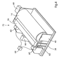
- FIG. 1 schematically shows a first embodiment of the gravure printing unit 10 according to the invention in a printing machine 12, in particular a combination printing press or hybrid printing machine.
- This embodiment of the gravure printing unit 10 has a printing cylinder 14 (gravure printing cylinder), which forms a printing gap in cooperation with a counter-pressure cylinder 16 and to which an inking device 18 is employed.
- the impression cylinder 16 rotates in the direction of rotation 20 and the impression cylinder 14 in the direction of rotation 22, and the printing material web moves in the transport direction 24 along its path.
- the axes of rotation of both cylinders are in this embodiment in a substantially horizontal plane.
- the inking device 18 is designed as a Farbschrakel 26, which is filled with gravure ink 28 and in the left sector of the jacket of the printing cylinder 14, in particular, the symmetry surface of the chambered doctor blade 26 is also substantially in the horizontal plane mentioned, is arranged.
- the squeegee 30 of the Farbschhuntrakels 26 is a negative doctor.
- the ink chamber doctor blade 26 has, as an anti-tabling device 32 in this embodiment, a third doctor blade, which is pronounced as a positive doctor blade.
- the printing cylinder 14 has a connecting element 36, which serves in this embodiment simultaneously as a connection to the drive (hidden in this view behind the impression cylinder 14).
- the printing cylinder 14 is detachably received on a connecting platform 38, which has a hinged end shield 40, the printing press 12.
- the counter-pressure cylinder 16 is accommodated by means of a counter-pressure cylinder bearing 42 on the printing press 12 independently of the impression cylinder 14 and of the ink application device 18.
- the other parts of the gravure printing unit 10 can be removed from the printing press 12, since they are releasably connectable to the printing machine 12, so that neither a web separation nor a change in the path of the printing material must be done by the printing press 12 to remove the gravure printing unit 10.
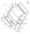
- FIG. 2 is a schematic representation of a second embodiment of the gravure printing unit 10 according to the invention in a printing machine 12, in particular a combination printing press or hybrid printing machine.
- This second embodiment of the gravure printing unit 10 has a printing cylinder 14 (gravure printing cylinder), which forms a printing gap in cooperation with a counter-pressure cylinder 16 and to which an inking device 18 is employed in the lower sector of the jacket of the printing cylinder 14.
- the impression cylinder 16 rotates in the direction of rotation 20 and the impression cylinder 14 in the direction of rotation 22, and the printing material web moves in the transport direction 24 along its path.
- the axes of rotation of both cylinders are in this embodiment in a substantially horizontal plane.
- the inking device 18 is designed as a color trough 44, which is filled with gravure ink 28.
- the squeegee 47 of the ink tray 44 is a positive squeegee.
- the inking device 18 has as anti-tabling device 32 in this embodiment, a third doctor blade, which is pronounced as a positive doctor.
- the inking device comprises a pressure roller 46 for improving the coloration of the printing cylinder 14.
- the pressure cylinder 14 has a connecting element 36 which serves in this embodiment simultaneously as a connection to the drive (concealed in this view behind the impression cylinder 14).
- the printing cylinder 14 is detachably received on a connecting platform 38, which has a hinged end shield 40, the printing press 12.
- the counter-pressure cylinder 16 is accommodated by means of a counter-pressure cylinder bearing 42 on the printing press 12 independently of the impression cylinder 14 and of the ink application device 18.
- the further parts of the gravure printing unit 10 can be removed from the printing press 12 in this embodiment, since they are detachably connectable to the printing machine 12, so that neither a web separation nor a change the path of the substrate web must be made by the printing press 12 to remove the gravure printing unit 10.
- FIG. 3 refers schematically to an advantageously further developed embodiment of the gravure printing unit 10 according to the invention in a printing press 12, in particular a combination printing press or hybrid printing press.
- this embodiment of the gravure printing unit 10 also has a printing cylinder 14 (intaglio printing cylinder) which, in cooperation with an impression cylinder 16, forms a printing nip and is connected to the printing cylinder an inking device 18, more specifically a Farbhuntrakel, is employed.
- the inking chamber doctor blade may alternatively to that in the FIG. 1 embodiment shown also be an upwardly open Farbschschakel, ie in the lateral direction only comprise a negative scraper on its underside.
- the impression cylinder 16 rotates in the direction of rotation 20 and the impression cylinder 14 in the direction of rotation 22, and the printing material web moves in the transport direction 24 along its path.
- the rotational axes of both cylinders and the inking device are in this embodiment in a substantially horizontal plane.
- the printing cylinder 14 has a first connecting element 48, which serves in this embodiment at the same time as a connection to the drive (concealed behind the printing cylinder 14 in this view).
- the printing cylinder 14 is detachably received on a first connection platform 50, which has a hinged end shield 40, the printing press 12.
- the inking device 18 has a second connecting element 50 which, in this embodiment, effects at least one positive connection with the printing press 12.
- the inking device 18 is detachably received on a second connection platform 52 by means of a bearing plate.
- Both the first connection platform 50 and the second connection platform 54 are designed to perform a relative movement to the printing machine 12:
- the first connection platform 50 allows a first shift in the direction 56 such that the impression cylinder 14 are turned on and off against the impression cylinder 16 to form the printing nip can.
- the second connection platform 54 allows a second shift in the direction 58 such that the inking device 18 can be turned on and off the jacket of the printing cylinder 14.
- the impression cylinder 16 is held in a fixed position by means of a counter-pressure cylinder bearing 42 on the printing press 12 independently of the impression cylinder 14 and of the ink application device 18.
- the other parts of the gravure printing unit 10 can be removed from the printing machine 12, since they are detachably connectable to the printing machine 12, so that neither a Web separation nor a change in the path of the substrate web must be done by the printing press 12 to remove the gravure printing unit 10.
- the gravure printing unit 10 comprises an additional deflection roller 78, which is arranged above the impression cylinder 16 with a distance of 0.5 m to the impression cylinder 16.
- the impression cylinder 16 is no longer maximally entwined in comparison to embodiments shown in the other figures.
- FIG. 4 is a schematic view of a preferred embodiment of a gravure printing module 70 of a gravure printing unit 10 according to the invention shown.
- the intaglio module 70 is suitable for receiving on a connection platform 38 of a printing machine 12, not shown here in detail, in particular a combination printing press or hybrid printing machine.
- the gravure module 70 produces a gravure printing unit.
- the gravure module 70 comprises a printing cylinder 14, which is rotatable by means of a separate drive 68.
- the pressure cylinder 14 can be accommodated by means of a cylinder mandrel or cylinder pin on a hinged end shield 40 of the connection platform 38 on the printing press 12.
- the printing cylinder 14 can be used as a cylinder, which receives a sleeve-shaped gravure form (here in FIG. 4 shown) or as a cylinder whose outer surface is engraved as a gravure form, be.
- the printing cylinder 14 is a Farbschrakel 26 assigned as an inking device 18.
- the ink chamber doctor blade 26 can be adjusted by means of a pneumatic adjusting device 60, in particular in the form of two pneumatic cylinders, as sketched here, to the printing cylinder and be turned off by him.
- the adjusting force can be controlled or regulated:
- the pneumatic adjusting device 60 is connected to a control device 64.
- the control device may be part of the gravure module 70 or part of the printing press 12 not shown here.
- the gravure module 70 comprises a device 66 for oscillating the ink chamber doctor blade 26.
- a modular design of the gravure printing unit 10 provides a particularly user-friendly design.
- FIG. 5 is a view of a preferred embodiment of the gravure printing unit 10 of the invention of a printing press 12, in particular a combination printing press or hybrid printing machine.
- a printing cylinder 14 cooperates with a counter-pressure cylinder 16 for printing on a printing material web 34, which is moved in the direction 24 through the printing press.
- the impression cylinder 14 is detachably received on the printing press 12 via a first connecting element 48 concealed in this drawing by means of a hinged end shield 40 of a first connecting platform 52.
- a separate drive 68 of the printing machine 12 is operatively connected to the printing cylinder 14 to rotate it.
- a Farbschhuntrakel 26 is employed: A second connecting element 50 of the ink chamber doctor blade 26 is detachably connected to a second connection platform 54 of the printing press. Analogous to the embodiment in FIG. 3 the connection platforms 52,54 are designed for the realization of a relative movement, so that employment and shutdowns can take place.
- the counter-pressure cylinder 16 is detachably connected to the printing press 12 independently of the impression cylinder 14 and the ink chamber doctor blade 26.
- the bearing plate 72 of the impression cylinder can be folded down, so that a recorded impression cylinder 16 can be removed and another impression cylinder 16 can be inserted. In this way, impression cylinders with different properties, such as different hardnesses or surface materials, depending on the application can be used particularly advantageously.
- a soft coated impression cylinder 16 is preferably used for a relatively hard impression cylinder 14.
- the contact force or the contact pressure of the chamber doctor blade 26 to the printing cylinder is controllable or regulated by means of the control device 64 and a concealed in this view pneumatic adjusting device.
- a means 66 for oscillation of the chambered doctor blade 26 is provided.
- this embodiment of the gravure printing unit 10 also has a cover 74, which is pivotable in the direction 76, so that on the one hand the gravure printing unit 10 can be closed for operation and on the other hand can be opened for maintenance or conversion.
- the intaglio printing unit 10 for a design of the gravure printing unit 10 for printing UV light-curing gravure ink, the intaglio printing unit according to the invention consists of parts of correspondingly resistant materials, the in principle known from the prior art, must be constructed and / or the engraving of the gravure cylinder must be adjusted accordingly.
Abstract
Description
Die Erfindung betrifft ein Tiefdruckwerk zum Bedrucken einer Bedruckstoffbahn in einer Druckmaschine, mit wenigstens einem Tiefdruckformzylinder, einer Farbauftragseinrichtung und einem Gegendruckzylinder.The invention relates to a gravure printing unit for printing a printing material web in a printing press, with at least one gravure printing cylinder, an inking device and a counter-pressure cylinder.
Bei Druckmaschinen zum Bedrucken von Etiketten, insbesondere Selbstklebeetiketten, ist in zunehmendem Maße eine große Flexibilität oder Variabilität gewünscht, um möglichst viele verschiedenartige Druckaufträge, insbesondere unter Erzeugung von speziellen optischen Effekten durch das gedruckte Bild oder den gedruckten Text, durchführen zu können. Zur Herstellung von Etiketten werden besonders häufig Druckmaschinen verwendet, die eine schmale Bahn eines Bedruckstoffs bearbeiten und eine Anzahl von Verbindungsplattformen oder Schnittstellen aufweisen, an denen jeweils eine Funktionseinheit oder ein Verfahrensmodul zum Drucken mit einem bestimmten Druckverfahren lösbar aufgenommen werden kann. Beispielsweise ist eine Ausführungsform einer derartigen Druckmaschine im Dokument
Aus den Dokumenten
Eine geläufig eingesetzte Konfiguration eines Tiefdruckwerks, wie es auch in Form einer Funktionseinheit für eine mit Verbindungsplattformen zum Wechseln ausgestattete Druckmaschine Verwendung findet, ist beispielsweise im Dokument
Des Weiteren ist aus dem Dokument
Im Dokument
Aus dem Dokument
Im Dokument
Im Dokument
An dieser Stelle sei ebenfalls angemerkt, dass bei Verwendung von lösungsmittelhaltigen Tiefdruckfarben Maßnahmen zum Explosionsschutz und zur umweltgerechten Entsorgung ergriffen werden müssen. Es wird eine isolierte Druckzone (Kapselung, Schutzummantelung), aus deren Gefahrenbereich insbesondere offene elektrische Komponenten entfernt sind, geschaffen. Häufig wird auch eine Absaugung der Lösungsmitteldämpfe vorgenommen. Werden alternativ zu lösungsmittelhaltigen Tiefdruckfarben lösungsmittelfreie, UV-Licht härtende Tiefdruckfarben eingesetzt, ist eine entsprechende Auswahl von Werkstoffen im Tiefdruckwerk und eine angepasste Gravur des Tiefdruckzylinders erforderlich. Auch wird dem Druckspalt des Tiefdruckwerks eine Einrichtung zur Beleuchtung mit UV-Licht nachgeordnet, typischerweise direkt nachgeordnet, gegebenenfalls mit dem Tiefdruckwerk integriert.At this point it should also be noted that when using solvent-based gravure inks measures for explosion protection and environmentally sound disposal must be taken. It is an isolated pressure zone (encapsulation, protective coating), from the danger zone in particular open electrical Components are removed, created. Frequently, a suction of the solvent vapors is made. If solvent-free, UV-curing gravure inks are used as an alternative to solvent-based gravure inks, an appropriate selection of materials in the gravure printing unit and an adapted engraving of the gravure cylinder is required. Also, the printing gap of the gravure printing unit downstream of a device for lighting with UV light, typically arranged directly downstream, optionally integrated with the gravure printing unit.
Aufgabe der vorliegenden Erfindung ist es, ein Tiefdruckwerk in einer Druckmaschine zum Bedrucken einer Bedruckstoffbahn zu schaffen, welches den schnellen Austausch durch ein Druckwerk, das nach einem anderen Druckverfahren arbeitet, gestattet.The object of the present invention is to provide a gravure printing unit in a printing machine for printing on a printing material web, which allows rapid replacement by a printing unit, which operates on a different printing method.
Diese Aufgabe wird erfindungsgemäß durch ein Tiefdruckwerk mit den Merkmalen gemäß Anspruch 1 gelöst. Vorteilhafte Weiterbildungen der Erfindung sind in den abhängigen Ansprüchen charakterisiert.This object is achieved by a gravure printing unit with the features of claim 1. Advantageous developments of the invention are characterized in the dependent claims.
Ein erfindungsgemäßes Tiefdruckwerk zum Bedrucken einer Bedruckstoffbahn in einer Druckmaschine, mit einem Druckzylinder (in dieser Darstellung als kurzer Ausdruck für Tiefdruckformzylinder verwendet), einer Farbauftragseinrichtung und einem Gegendruckzylinder, weist wenigstens ein Verbindungselement zur lösbaren Aufnahme an wenigstens einer in im Wesentlichen horizontaler Richtung verschiebbaren Verbindungsplattform der Druckmaschine und zur Herstellung einer lösbaren Wirkverbindung mit einem separaten Antrieb für den einen Druckzylinder auf, so dass der Druckzylinder und die Farbauftragseinrichtung von der wenigstens einen Verbindungsplattform trennbar sind, wobei der Gegendruckzylinder in der Druckmaschine verbleibt, also, mit anderen Worten, der eine Druckzylinder und die Farbauftragseinrichtung sind trennbar, ohne den Gegendruckzylinder von der Druckmaschine zu trennen.An intaglio printing unit according to the invention for printing on a printing material web in a printing press, with a printing cylinder (used in this illustration as a short print for rotogravure cylinder), an inking device and a counter-pressure cylinder, has at least one connecting element for releasably receiving at least one in substantially horizontal direction movable connection platform Printing press and for producing a releasable operative connection with a separate drive for the one printing cylinder, so that the printing cylinder and the inking device are separable from the at least one connecting platform, wherein the impression cylinder remains in the printing press, that is, in other words, a pressure cylinder and the inking device are separable without separating the impression cylinder from the printing press.
Die Trennung beziehungsweise das Schließen der Verbindung kann dabei bevorzugt erfolgen, ohne den Verlauf der Bedruckstoffbahn durch die Druckmaschine zu verändern und/oder ohne die Bedruckstoffbahn zu durchtrennen. Erfindungsgemäß kann es eine erste Anzahl, insbesondere Mehrzahl, von Verbindungselementen geben, die nur zur lösbaren Aufnahme an wenigstens einer Verbindungsplattform der Druckmaschine dienen, und eine zweite Anzahl, insbesondere eines oder eine Mehrzahl, von Verbindungselementen geben, die sowohl zur lösbaren Aufnahme an wenigstens einer Verbindungsplattform der Druckmaschine als auch zur Herstellung einer lösbaren Wirkverbindung mit einem separaten Antrieb für den Druckzylinder.The separation or closing of the connection can preferably take place without changing the course of the printing substrate through the printing press and / or without severing the printing material web. According to the invention, there may be a first number, in particular a plurality, of connecting elements which serve only for detachable reception on at least one connecting platform of the printing press, and a second number, in particular one or a plurality, of connecting elements which are capable of detachable reception on at least one of them Connecting platform of the printing press as well as for the production of a releasable operative connection with a separate drive for the printing cylinder.
Der Druckzylinder kann derart ausgeführt sein, dass er eine Tiefdruckform, insbesondere in Form einer Hülse, aufnehmen kann oder dass seine Mantelfläche eine gravierte Tiefdruckform bildet.The printing cylinder can be designed such that it can receive a gravure form, in particular in the form of a sleeve, or that its lateral surface forms an engraved gravure form.
Erfindungsgemäß weist das Tiefdruckwerk wenigstens zwei Verbindungselemente auf, wobei wenigstens ein erstes Verbindungselement zur lösbaren Aufnahme des Druckzylinders an einer ersten Verbindungsplattform der Druckmaschine und wenigstens ein zweites Verbindungselement zur lösbaren Aufnahme der Farbauftragseinrichtung an einer zweiten Verbindungsplattform der Druckmaschine geeignet oder ausgeführt ist. Mit anderen Worten, sowohl der Druckzylinder als auch die Farbauftragseinrichtung können unabhängig voneinander von der Druckmaschine getrennt und an der Druckmaschine angebracht werde. Dabei sind die erste und die zweite Verbindungsplattform relativ zueinander bewegbar, insbesondere verschiebbar oder schwenkbar. Durch eine relative Bewegung, insbesondere ein seitliches Verschieben, zueinander ist eine Anpassung an unterschiedliche Tiefdruckzylinderdurchmesser (formatabhängig) möglich. Die Zugänglichkeit kann entsprechend der verschiedenen Operationen (Drucken, Reinigen, Einrichten) erhöht oder verringert werden.According to the invention, the gravure printing unit has at least two connecting elements, wherein at least one first connecting element for releasably receiving the printing cylinder on a first connection platform of the printing machine and at least one second connecting element for releasably receiving the inking device on a second connection platform of the printing machine is suitable or executed. In other words, both the printing cylinder and the inking device can be independently separated from the printing machine and attached to the printing press. In this case, the first and the second connection platform are movable relative to each other, in particular displaceable or pivotable. By a relative movement, in particular a lateral displacement, an adaptation to different gravure cylinder diameter (format dependent) is possible. The accessibility can be increased or decreased according to the various operations (printing, cleaning, setting up).
Insbesondere kann die Druckmaschine eine Druckmaschine in Reihenbauweise, das heißt mit in horizontaler Richtung angeordneten Druckwerken sein.Especially For example, the printing machine can be a series-produced printing machine, that is to say printing units arranged in the horizontal direction.
Alternativ oder in Ergänzung zu den bereits beschriebenen Merkmalen kann die Farbauftragseinrichtung ein mit dem Druckzylinder zusammenwirkendes Farbkammerrakel sein. Das Farbkammerrakel kann offen, d. h. einen Farbkreislauf mit einem kontinuierlichen Farbfluss durch die Farbkammer aufweisen, oder geschlossen sein. Das Farbkammerrakel kann ein Rakel aufweisen, das unter einem spitzen Winkel mit der Drehrichtung der Mantelfläche angestellt ist (negatives Rakel), so dass mit weniger Druck zur Anstellung des Rakel an die Mantelfläche gearbeitet werden kann. Die Geschwindigkeitsabhängigkeit der Druckqualität kann reduziert werden. Eine geringere Abnutzung des Rakels ist in vorteilhafter Weise die Folge. In vorteilhafter Weiterentwicklung kann das Tiefdruckwerk eine pneumatische Einrichtung zur Anstellung des Farbkammerrakels an den Druckzylinder, insbesondere in Form von einer Anzahl von Pneumatikzylindern, aufweisen. Der Anstellungsdruck kann in Abhängigkeit der Druckgeschwindigkeit und/oder der Betriebsdauer des Rakels (Maß für die Rakelabnutzung) gesteuert oder geregelt sein. Alternativ oder in Ergänzung dazu kann das Tiefdruckwerk eine Bewegungseinrichtung zur seitlichen Oszillation des Farbkammerrakels, d. h. im Wesentlichen parallel zur Rotationsachse des Druckzylinders aufweisen.Alternatively or in addition to the features already described, the inking device may be a cooperating with the printing cylinder ink chamber doctor blade. The ink chamber doctor blade can be open, d. H. have a color cycle with a continuous flow of color through the ink chamber, or be closed. The ink chamber doctor blade can have a doctor blade, which is set at an acute angle with the direction of rotation of the lateral surface (negative doctor), so that it is possible to work with less pressure to set up the doctor blade on the lateral surface. The speed dependency of the print quality can be reduced. A lower wear of the doctor blade is advantageously the result. In an advantageous further development, the gravure printing unit can have a pneumatic device for adjusting the ink chamber doctor blade to the printing cylinder, in particular in the form of a number of pneumatic cylinders. The application pressure may be controlled or regulated depending on the printing speed and / or the operating time of the doctor blade (measure of doctor blade wear). Alternatively, or in addition to the gravure printing unit, a movement device for lateral oscillation of the Farbkammerrakels, d. H. have substantially parallel to the axis of rotation of the printing cylinder.
Bevorzugt kann eine geometrische Ausrichtung der Farbauftragseinrichtung, insbesondere des Farbkammerrakels, zum Tiefdruckzylinder über antriebsseitig und bedienseitig individuell, voneinander unabhängig einstellbare Exzenter erfolgen. Die Exzenter können als Teil der Verbindungsplattform, also mit der Druckmaschine integriert, ausgeführt sein. Die Druckzustellung der Farbauftragseinrichtung, insbesondere des Farbkammerrakels, kann über wenigstens zwei parallel geschaltete Pneumatikzylinder als Teil der Farbauftragseinrichtung sein.Preferably, a geometric orientation of the inking device, in particular of the ink chamber doctor, to the gravure cylinder on the drive side and operator side individually, independently adjustable eccentric done. The eccentrics can be designed as part of the connection platform, ie integrated with the printing press. The printing delivery of the inking device, in particular of the ink chamber doctor blade, can be via at least two parallel connected pneumatic cylinders as part of the inking device.
Es ist des weiteren vorteilhaft, dass das Tiefdruckwerk eine separate Antriebvorrichtung für den Druckzylinder (Einzelantrieb, d. h. getrennt von den Antrieben zur Erzeugung weiterer Bewegungsformen in der Druckmaschine, wie Bedruckstofftransport oder dem Betrieb anderer Druckwerke oder Bearbeitungswerke) aufweist. Die separate Antriebsvorrichtung ist insbesondere vom Antrieb des Gegendruckzylinders im Tiefdruckwerk unabhängig. Insbesondere kann das Tiefdruckwerk eine separate Antriebsvorrichtung zum direkten Antrieb des Druckzylinders aufweist. Die Wirkverbindung kann darin bestehen, dass direkt (mit oder ohne Zwischenschaltung eines Getriebes oder Riemens) die Welle des Druckzylinders mit der Antriebsvorrichtung verbunden und von dieser in Rotation versetzt wird. Die Antriebsvorrichtung kann ein Servomotor sein. Beim Einlaufen der Druckmaschine ist ein Einlaufen des Tiefdruckwerks, insbesondere mit Farbkammerrakel, ohne Makulaturverluste möglich. Beim Drucken sind dank des Einzelantriebs Formatlängenkorrekturen möglich. Bevorzugt ist dabei, dass die separate Antriebsvorrichtung in der Druckmaschine aufgenommen und lösbar verbindbar mit dem Druckzylinder ist. Insbesondere kann wenigstens eines der Verbindungselemente des Tiefdruckwerks nicht nur eine mechanische Verbindung, sondern gleichzeitig eine Antriebsverbindung darstellen.It is also advantageous that the gravure printing unit a separate drive device for the printing cylinder (single drive, ie separated from the drives for generating other forms of motion in the printing press, such as substrate transport or the Operation of other printing units or processing plants). The separate drive device is in particular independent of the drive of the impression cylinder in the gravure printing unit. In particular, the gravure printing unit may have a separate drive device for direct drive of the printing cylinder. The operative connection can be that directly (with or without the interposition of a transmission or belt), the shaft of the printing cylinder is connected to the drive device and rotated by this. The drive device may be a servomotor. When entering the printing machine is a shrinkage of the gravure printing plant, especially with Farbkammerrakel, without waste losses possible. When printing, format length corrections are possible thanks to the single drive. It is preferred that the separate drive device is received in the printing press and releasably connectable with the printing cylinder. In particular, at least one of the connecting elements of the gravure printing unit can not only constitute a mechanical connection but at the same time a drive connection.
Alternativ oder in Ergänzung zu den bereits beschriebenen Merkmalen kann das Tiefdruckwerk eine Antischabloniereinrichtung, insbesondere in Form eines dritten Rakels oder einer Walze, welche auf der Mantelfläche des Druckzylinders abrollt, so dass eine Verwirbelung der Strömung im Reservoir der Farbauftragseinrichtung entsteht, umfassen. In einer besonderen Ausführungsform kann die Walze gummibeschichtet sein. Die Walze kann insbesondere eine geeignete Gravur zur verbesserten Traktion aufweisen. Des Weiteren können die Farbauftragseinrichtung und/oder der Druckzylinder des Tiefdruckwerks wenigstens ein Heizelement aufweist, so dass die zu verdruckende Farbe temperierbar ist. Für typische Tiefdruckfarben erfolgt eine Erwärmung auf Temperaturen zwischen 35 und 40 Grad Celsius. Durch die Temperierung werden die Fliesseigenschaften der Tiefdruckfarbe beeinflusst, so dass die Näpfchen oder Vertiefungen im Mantel des Tiefdruckzylinders verbessert gefüllt werden können. Im Druckbild kann sich dieses durch eine höhere Schichtdicke und einen höheren Glanz auswirken.Alternatively or in addition to the features already described, the gravure printing unit may comprise an antifogging device, in particular in the form of a third squeegee or a roller, which rolls on the lateral surface of the printing cylinder, so that a turbulence of the flow in the reservoir of the inking device is formed. In a particular embodiment, the roller may be rubber coated. In particular, the roller may have a suitable engraving for improved traction. Furthermore, the inking device and / or the printing cylinder of the gravure printing unit can have at least one heating element, so that the color to be printed can be tempered. For typical gravure inks, it is heated to temperatures between 35 and 40 degrees Celsius. By tempering the flow properties of gravure ink are affected, so that the wells or wells can be filled improved in the shell of the gravure cylinder. In the printed image, this can have an effect through a higher layer thickness and a higher gloss.
Alternativ oder in Ergänzung zu den bereits beschriebenen Merkmalen kann der Gegendruckzylinder lösbar verbunden in der Druckmaschine aufgenommen sein. Gegebenenfalls ist es erforderlich, beim Wechsel von einem ersten zu einem zweiten Druckverfahren auch den Gegendruckzylinder zu tauschen. Auch kann anwendungsspezifisch ein Gegendruckzylinder zum Einsatz gelangen, dessen Mantelfläche je nach Anwendung eine bestimmte Härte aufweist.Alternatively or in addition to the features already described, the counter-pressure cylinder can be detachably connected in the printing press. It may be necessary to change from a first to a second one Printing process also to replace the impression cylinder. Also, application-specific, a counter-pressure cylinder can be used, whose lateral surface has a certain hardness depending on the application.
Bevorzugt ist das erfindungsgemäße Tiefdruckwerk derart ausgeführt, dass der Druckzylinder und der Gegendruckzylinder derart in der Druckmaschine angeordnet sind, dass ihre Rotationsachsen im Wesentlichen in einer horizontalen Ebene liegen. Diese Anordnung ist unter anderem besonders vorteilhaft, wenn Zylinder unterschiedlicher Durchmesser eingesetzt werden sollen, ohne die grundsätzliche Geometrie des Tiefdruckwerks zu verändern. Des Weiteren entspricht dieser Aufbau vorteilhaften Anordnungen von Druckwerken, die nach anderen Druckverfahren arbeiten, so dass eine Standardisierung erreicht ist. Das erfindungsgemäße Tiefdruckwerk kann aber auch derart ausgeführt sein, dass die Rotationsachsen von Druckzylinder und Gegendruckzylinder nicht in einer horizontalen Ebene liegen.Preferably, the gravure printing unit according to the invention is designed such that the printing cylinder and the impression cylinder are arranged in the printing press such that their axes of rotation lie substantially in a horizontal plane. Among other things, this arrangement is particularly advantageous when cylinders of different diameters are to be used without changing the fundamental geometry of the gravure printing unit. Furthermore, this structure corresponds to advantageous arrangements of printing units that work according to other printing methods, so that a standardization is achieved. However, the intaglio printing unit according to the invention can also be designed in such a way that the axes of rotation of the impression cylinder and impression cylinder are not in a horizontal plane.
Auch kann das Tiefdruckwerk zum Verdrucken von mit UV-Licht härtender Druckfarbe (lösungsmittelfreie Tiefdruckfarbe) einsetzbar ausgeführt sein.The gravure printing unit can also be designed for printing UV-curable printing ink (solvent-free gravure ink).
In einer vorteilhaften Ausführungsform kann das erfindungsgemäße Tiefdruckwerk des weiteren wenigstens eine zusätzliche Umlenkrolle aufweisen, welche derart oberhalb des Gegendruckzylinders angeordnet ist, dass die Umschlingung des Gegendruckzylinders durch die Bedruckstoffbahn im Vergleich zum Betrieb ohne die wenigstens eine Umlenkrolle reduziert ist. Auf diese Weise wird der Bedruckstoffbahn eine längere Verlaufstrecke nach dem Druck ermöglicht, beispielsweise zur längeren Trocknung. Diese ist insbesondere zur Erzeugung eines Glanzeffektes, beispielsweise beim Verdrucken von Lacken, vorteilhaft.In an advantageous embodiment, the gravure printing unit according to the invention may further comprise at least one additional deflection roller, which is arranged above the impression cylinder in such a way that the looping of the impression cylinder through the printing substrate web is reduced compared to operation without the at least one deflection roller. In this way, the printing material is a longer course after the printing allows, for example, for longer drying. This is particularly advantageous for producing a gloss effect, for example when printing paints.
Im Zusammenhang des erfinderischen Gedankens steht auch ein Tiefdruckwerkmodul mit wenigstens einem Druckzylinder und einer Farbauftragseinrichtung, welches in Zusammenwirkung mit einem Gegendruckzylinder, der in einer Druckmaschine aufgenommen ist, ein Tiefdruckwerk mit Merkmalen gemäß dieser Darstellung realisiert. Das Tiefdruckwerkmodul kann insbesondere als Kassette, Aufsatz oder Einschub ausgeführt sein.In the context of the inventive idea is also a gravure printing module with at least one printing cylinder and an inking device, which realized in cooperation with a counter-pressure cylinder, which is housed in a printing press, a gravure printing unit with features according to this representation. The gravure printing module can in particular as a cassette, essay or insert be executed.
Des Weiteren steht im Zusammenhang des erfinderischen Gedankens auch eine Druckmaschine, geeignet zum Bedrucken einer Bedruckstoffbahn mit einer Mehrzahl von verschiedenen Druckverfahren, insbesondere eine Hybriddruckmaschine oder Kombinationsdruckmaschine. Die erfindungsgemäße Druckmaschine zeichnet sich durch wenigstens ein Tiefdruckwerk mit Merkmalen gemäß dieser Darstellung aus. Insbesondere kann die Druckmaschine eine Schmalbahndruckmaschine sein. Insbesondere kann die Druckmaschine in Reihenbauweise ausgeführt sein. Insbesondere kann die Druckmaschine eine Etikettendruckmaschine, Klebeetikettendruckmaschine oder Selbstklebeetikettendruckmaschine sein.Furthermore, in the context of the inventive concept, a printing machine is also suitable for printing on a printing material web with a plurality of different printing processes, in particular a hybrid printing press or a combination printing press. The printing machine according to the invention is characterized by at least one gravure printing unit with features according to this representation. In particular, the printing press can be a narrow-web printing press. In particular, the printing press can be designed in series construction. In particular, the printing press may be a label printing machine, adhesive label printing machine or self-adhesive label printing machine.
Weitere Vorteile und vorteilhafte Ausführungsformen und Weiterbildungen der Erfindung werden anhand der nachfolgenden Figuren sowie deren Beschreibungen dargestellt. Es zeigt im Einzelnen:
- Figur 1
- eine schematische Darstellung einer ersten Ausführungsform des erfindungsgemäßen Tiefdruckwerks,
- Figur 2
- eine schematische Darstellung einer zweiten Ausführungsform des erfindungsgemäßen Tiefdruckwerks,
- Figur 3
- eine schematische Darstellung einer vorteilhaft weiterentwickelten Ausführungsform des erfindungsgemäßen Tiefdruckwerks,
- Figur 4
- eine Ansicht einer bevorzugten Ausführungsform eines Tiefdruckmoduls eines erfindungsgemäßen Tiefdruckwerks, und
- Figur 5
- eine Ansicht einer bevorzugten Ausführungsform des erfindungsgemäßen Tiefdruckwerks.
- FIG. 1
- a schematic representation of a first embodiment of the gravure printing unit according to the invention,
- FIG. 2
- a schematic representation of a second embodiment of the gravure printing unit according to the invention,
- FIG. 3
- a schematic representation of an advantageous further developed embodiment of the gravure printing unit according to the invention,
- FIG. 4
- a view of a preferred embodiment of a gravure module of a gravure printing unit according to the invention, and
- FIG. 5
- a view of a preferred embodiment of the gravure printing unit according to the invention.
Die
Die
Die
Die in
In der
Die
- 1010
- TiefdruckwerkGravure printing unit
- 1212
- Druckmaschinepress
- 1414
- Druckzylinderpressure cylinder
- 1616
- GegendruckzylinderImpression cylinder
- 1818
- FarbauftragseinrichtungInking device
- 2020
- Drehrichtung GegendruckzylinderDirection of rotation of impression cylinder
- 2222
- Drehrichtung DruckzylinderDirection of rotation of the pressure cylinder
- 2424
- BahntransportrichtungRailway transport direction
- 2626
- FarbkammerrakelInk chamber doctor blade
- 2828
- TiefdruckfarbeGravure ink
- 3030
- negatives Rakelnegative squeegee
- 3232
- AntischabloniereinrichtungAntischabloniereinrichtung
- 3434
- Bedruckstoffbahnprinting material
- 3636
- Verbindungselementconnecting element
- 3838
- Verbindungsplattformconnection platform
- 4040
- Lagerschildend shield
- 4242
- GegendruckzylinderlagerImpression cylinder bearings
- 4444
- Farbwannepaint tray
- 4646
- Anpresswalzepressure roller
- 4747
- positives Rakelpositive squeegee
- 4848
- erstes Verbindungselementfirst connecting element
- 5050
- zweites Verbindungselementsecond connecting element
- 5252
- erste Verbindungsplattformfirst connection platform
- 5454
- zweite Verbindungsplattformsecond connection platform
- 5656
- erste Verschiebungsrichtungfirst shift direction
- 5858
- zweite Verschiebungsrichtungsecond shift direction
- 6060
- pneumatische Anstellungseinrichtungpneumatic adjusting device
- 6262
- Anstellungsrichtungemployment direction
- 6464
- Steuerungseinrichtungcontrol device
- 6666
- Oszillationseinrichtungoscillation
- 6868
- separater Antriebseparate drive
- 7070
- TiefdruckmodulGravure printing module
- 7272
- Lagerschild des GegendruckzylindersEnd shield of the impression cylinder
- 7474
- Abdeckhaubecover
- 7676
- Schwenkrichtungpan direction
- 7878
- Umlenkrolleidler pulley
Claims (14)
- Gravure printing unit (10) for printing a web of material (34) in a printing press (12) including at least one printing cylinder designed as a gravure forme cylinder (14), an ink application device (18) and an impression cylinder (16) and at least one connecting element (36, 38, 50) for releasable reception on at least one connecting platform (38, 52, 54) of the printing press (12) and for creating a releasable operative connection to a separate drive (68) for the gravure forme cylinder (14), thus causing the gravure forme cylinder (14) and the ink application device (18) to be separatable from the at least one connecting platform (38, 52, 54) with the impression cylinder (16) remaining in the printing press (12),
characterized by
the fact that the gravure printing unit (10) has at least two connecting elements (48, 50), at least a first connecting element (48) being designed for releasable reception of the printing cylinder (14) on a first connecting platform (52) of the printing press (12) and at least a second connecting element (50) being designed for releasable reception of the ink application device (18) to a second connecting platform (54) of the printing press (12), and by the fact that the first and second connecting platforms (52, 54) are designed to be movable relative to each other. - Gravure printing unit (10) according to one of the preceding claims,
characterized by
the fact that the at least one connecting platform (38, 48, 50) is designed to be movable essentially in the horizontal direction. - Gravure printing unit (10) according to one of the preceding claims,
characterized by
the fact that the ink application device (18) is a chambered doctor blade (26) cooperating with the printing cylinder (14). - Gravure printing unit (10) according to Claim 6,
characterized by
the fact that the gravure printing unit (10) includes a pneumatic device (60) for engaging the chambered doctor blade (26) with the gravure forme cylinder (14). - Gravure printing unit (10) according to Claim 6 or 7,
characterized by
the fact that the gravure printing unit (10) includes a moving device (66) for laterally oscillating the chambered doctor blade (26). - Gravure printing unit (10) according to one of the preceding claims,
characterized by
the fact that the gravure printing unit (10) includes a separate drive device (68) for directly driving the printing cylinder (14). - Gravure printing unit (10) according to Claim 9,
characterized by
the fact that the separate drive device (68) is received in the printing press (12) and is releasably connectible to the gravure forme cylinder (14). - Gravure printing unit (10) according to one of the preceding claims,
characterized by
the fact that the gravure printing unit (10) comprises an anti-ghosting device (32). - Gravure printing unit (10) according to one of the preceding claims,
characterized by
the fact that the ink application device (18) and/or the gravure forme cylinder (14) includes at least one heating element so that the ink to be used for printing is heatable. - Gravure printing unit (10) according to one of the preceding claims,
characterized by
the fact that the impression cylinder (16) is received in the printing press (12) in a releasably connected way. - Gravure printing unit (10) according to one of the preceding claims,
characterized by
the fact that the gravure forme cylinder (14) and the impression cylinder (16) are arranged in the printing press (12) in such a way that their axes of rotation are essentially located in a horizontal plane. - Gravure printing unit (10) according to one of the preceding claims,
characterized by
the fact that the gravure printing unit (10) is designed so as to be usable for printing with printing inks that are curable by UV light. - Printing press (12) suited for printing on a web of printing material (34) using a plurality of different printing processes,
characterized by
at east one gravure printing unit (10) according to one of the preceding claims. - Printing press (12) according to Claim 13,
characterized by
the fact that the gravure printing unit (10) includes at least one additional deflection roller (78) arranged above the impression cylinder (16) in such a way that the amount of wrap of the web of printing material (34) around the impression cylinder (16) is reduced compared to an operation without the at least one deflection roller (78).
Applications Claiming Priority (2)
| Application Number | Priority Date | Filing Date | Title |
|---|---|---|---|
| DE200510003206 DE102005003206A1 (en) | 2005-01-24 | 2005-01-24 | Gravure printing unit for printing machine has connecting element for detachably retaining connecting platform for production of working connection with separate drive so that printing cylinder and color application device are connected |
| DE200510044516 DE102005044516A1 (en) | 2005-09-16 | 2005-09-16 | Gravure printing unit for printing machine has connecting element for detachably retaining connecting platform for production of working connection with separate drive so that printing cylinder and color application device are connected |
Publications (2)
| Publication Number | Publication Date |
|---|---|
| EP1683633A1 EP1683633A1 (en) | 2006-07-26 |
| EP1683633B1 true EP1683633B1 (en) | 2011-09-21 |
Family
ID=36295496
Family Applications (1)
| Application Number | Title | Priority Date | Filing Date |
|---|---|---|---|
| EP06000705A Not-in-force EP1683633B1 (en) | 2005-01-24 | 2006-01-13 | Gravure printing unit for printing on a web in a printing machine |
Country Status (5)
| Country | Link |
|---|---|
| US (1) | US20060162592A1 (en) |
| EP (1) | EP1683633B1 (en) |
| AT (1) | ATE525209T1 (en) |
| DK (1) | DK1683633T3 (en) |
| HK (1) | HK1090611A1 (en) |
Families Citing this family (7)
| Publication number | Priority date | Publication date | Assignee | Title |
|---|---|---|---|---|
| CN101484253B (en) * | 2006-07-05 | 2011-03-09 | 菲奇工程技术有限公司 | Roll support and roll coating head, roll coating apparatus and coating method |
| CA2667278A1 (en) * | 2006-10-20 | 2008-05-02 | Soligie, Inc. | Patterned printing plates and processes for printing electrical elements |
| DE502007003847D1 (en) * | 2007-04-03 | 2010-07-01 | Applied Materials Inc | Apparatus for continuously coating a band-shaped substrate |
| DE102008018806A1 (en) | 2007-05-11 | 2008-11-13 | Gallus Ferd. Rüesch AG | Printing press for laminates and other materials has several printing stations and guide rollers with one guide roller axially adjustable to maintain alignment |
| DE102007026027A1 (en) * | 2007-06-04 | 2008-12-11 | Gallus Ferd. Rüesch AG | press |
| KR101212588B1 (en) | 2010-07-12 | 2012-12-14 | 강상중 | Offset rotary press for providing various sized printings with ease |
| WO2014114466A2 (en) * | 2013-01-24 | 2014-07-31 | Windmöller & Hölscher Kg | Gravure printing machine and inking unit |
Family Cites Families (26)
| Publication number | Priority date | Publication date | Assignee | Title |
|---|---|---|---|---|
| US2242045A (en) * | 1937-10-26 | 1941-05-13 | John Waldron Corp | Combination surface and intaglio printing machine |
| DE2312175C2 (en) * | 1973-03-12 | 1975-04-30 | Fischer & Krecke, 4800 Bielefeld | Register adjustment of the forme or plate cylinders on rotary printing machines with central cylinders |
| JPS5444910A (en) * | 1977-09-14 | 1979-04-09 | Kataoka Kikai Seisakusho Kk | Printing unit of rotary press |
| US4384522A (en) | 1977-12-07 | 1983-05-24 | Paper Converting Machine Company | Apparatus for producing business forms |
| US4398463A (en) * | 1981-08-19 | 1983-08-16 | Motter Printing Press Co. | Non-repeat doctor blade drive |
| DE3402515C2 (en) * | 1984-01-26 | 1986-11-20 | M.A.N.- Roland Druckmaschinen AG, 6050 Offenbach | Rotary offset printing machine |
| DE3543704A1 (en) * | 1985-12-11 | 1987-06-19 | Md Papierfabrik Pasing Nicolau | DEVICE AND METHOD FOR PRINTING A TRAIN |
| IT1252305B (en) * | 1990-09-17 | 1995-06-08 | C M F S P A | FLEXOGRAPHIC OR INDIRECT ROTOCALCO PRINTING MACHINE. |
| DE4108883A1 (en) * | 1991-03-19 | 1992-09-24 | Sengewald Karl H Gmbh | PRINTING DEVICE |
| DE4139343C2 (en) | 1991-11-29 | 1995-04-13 | Schepers Hans Georg | Trial printing machine |
| DE4242582C2 (en) | 1992-12-16 | 1998-03-19 | Sebald U E | Doctor blade arrangement |
| AU2405795A (en) | 1994-04-28 | 1995-11-29 | Nilpeter A/S | A printing apparatus comprising at least one printing module |
| DE19513536A1 (en) | 1995-04-10 | 1996-10-17 | Heidelberger Druckmasch Ag | Printing machine with several printing units |
| DE19516004C2 (en) * | 1995-05-02 | 1997-05-07 | Windmoeller & Hoelscher | Printing press |
| US5632203A (en) * | 1995-06-14 | 1997-05-27 | Quad Graphics, Inc. | Anti-ghosting roller |
| EP0812681A1 (en) * | 1996-06-12 | 1997-12-17 | Fischer & Krecke Gmbh & Co. | Printing machine |
| NL1005525C2 (en) * | 1997-03-13 | 1998-09-15 | Multi Print Systems M P S B V | Printing machine with interchangeable ink applicators. |
| US5943955A (en) * | 1997-08-29 | 1999-08-31 | Goss Graphic Systems, Inc. | Printing press having cantilevered self-driven cylinders |
| DE59800788D1 (en) * | 1998-01-28 | 2001-07-05 | Fischer & Krecke Gmbh & Co | Squeegee seal |
| IT1299644B1 (en) * | 1998-02-05 | 2000-03-24 | Uteco Spa Roto Flexo & Convert | MACHINE FOR ROTOCALCO PRINTING AND FOR PAINTING UP TO EIGHT COLORS |
| US6165319A (en) * | 1998-05-11 | 2000-12-26 | Fort James Corporation | Printed, soft, bulky single-ply absorbent paper having a serpentine configuration and low sidedness and methods for its manufacture |
| US6082257A (en) * | 1998-08-19 | 2000-07-04 | Howard W. DeMoore | Printing unit with anilox roller bearer positioning |
| DE59802253D1 (en) * | 1998-08-29 | 2002-01-10 | Fischer & Krecke Gmbh & Co | Method and device for collision monitoring in printing machines |
| JP4921661B2 (en) * | 1999-06-22 | 2012-04-25 | トレス プロダクション アクティーゼルスカブ | Doctor blade system |
| DE29918488U1 (en) * | 1999-10-20 | 1999-12-30 | Roland Man Druckmasch | Sheet-fed rotary printing machine with printing units for multi-color printing and at least one coating unit |
| EP1362696B1 (en) * | 2002-05-18 | 2006-09-20 | Fischer & Krecke GmbH & Co. KG | Printing machine with doctoring device |
-
2006
- 2006-01-13 EP EP06000705A patent/EP1683633B1/en not_active Not-in-force
- 2006-01-13 AT AT06000705T patent/ATE525209T1/en active
- 2006-01-13 DK DK06000705.1T patent/DK1683633T3/en active
- 2006-01-24 US US11/338,245 patent/US20060162592A1/en not_active Abandoned
- 2006-10-12 HK HK06111201.6A patent/HK1090611A1/en not_active IP Right Cessation
Also Published As
| Publication number | Publication date |
|---|---|
| DK1683633T3 (en) | 2011-12-05 |
| EP1683633A1 (en) | 2006-07-26 |
| HK1090611A1 (en) | 2006-12-29 |
| US20060162592A1 (en) | 2006-07-27 |
| ATE525209T1 (en) | 2011-10-15 |
Similar Documents
| Publication | Publication Date | Title |
|---|---|---|
| EP2103429B1 (en) | Printing unit and press with format change | |
| EP2042315B1 (en) | Printing unit and printing press | |
| EP1683633B1 (en) | Gravure printing unit for printing on a web in a printing machine | |
| EP3043994B1 (en) | Printing press for security printing as well as a method for exchanging a printing plate and for a press start-up | |
| EP0586881A2 (en) | Rotary web printing machine particularly for printing thick paper webs | |
| EP3043997B1 (en) | Method and device for adjusting ink carrying rotary bodies of a printing press | |
| DE102007017097B4 (en) | Printing cylinder changing device for printing length variable printing units in a full rotation printing press | |
| DE4218422C2 (en) | Sheet-fed offset rotary press with removable imprinting or finishing unit | |
| DE102009019590B4 (en) | Machining plant for processing a substrate | |
| DE10024350A1 (en) | Changeable printer for conversion between flexographic and gravure printing has counter roller, central roller and change roller with flexographic and gravure doctor blades for different use | |
| DE102013204892B4 (en) | Printing machine for hollow bodies | |
| EP1303405B1 (en) | Printing group of an offset rotary printing machine | |
| DE10257282A1 (en) | Process for the flying change of printing plates in sheet-fed offset rotary printing machines | |
| DE102005044516A1 (en) | Gravure printing unit for printing machine has connecting element for detachably retaining connecting platform for production of working connection with separate drive so that printing cylinder and color application device are connected | |
| DE102008011203A1 (en) | Gravure printing process with exchangeable printing plate | |
| DE102005003206A1 (en) | Gravure printing unit for printing machine has connecting element for detachably retaining connecting platform for production of working connection with separate drive so that printing cylinder and color application device are connected | |
| DE102009020013B4 (en) | Printing unit for printing on a printing material web with a cylinder and method for exposing or removably connected receiving an operator-side cylinder journal | |
| DE102005027543B3 (en) | Web-fed letter press for printing shop, has inking system provided for form cylinder or plate cylinder, where form cylinder or plate cylinder is alternatively brought into printing position and cylinders have different diameters | |
| DE102006008348B4 (en) | press | |
| DE102019111802A1 (en) | Method for operating a printing unit, substrate section and printing unit | |
| DE102006051278A1 (en) | Device and method for the finishing of sheet-like substrates in a ground pressure machine | |
| DE102011006701A1 (en) | Arc processing machine has elastic support that is detachably arranged on outer surface of cylinders, and conveyor that is provided with sheet temporary holding unit that is guided in cylinder channel of forme cylinder | |
| DE10329427B4 (en) | Method of operating an inking unit | |
| EP1932667A1 (en) | Printing device for a variable format roller printing press | |
| DE102019111804A1 (en) | Method for setting and / or changing an ink transfer, printing unit and printing machine with a printing unit |
Legal Events
| Date | Code | Title | Description |
|---|---|---|---|
| PUAI | Public reference made under article 153(3) epc to a published international application that has entered the european phase |
Free format text: ORIGINAL CODE: 0009012 |
|
| AK | Designated contracting states |
Kind code of ref document: A1 Designated state(s): AT BE BG CH CY CZ DE DK EE ES FI FR GB GR HU IE IS IT LI LT LU LV MC NL PL PT RO SE SI SK TR |
|
| AX | Request for extension of the european patent |
Extension state: AL BA HR MK YU |
|
| 17P | Request for examination filed |
Effective date: 20060926 |
|
| AKX | Designation fees paid |
Designated state(s): AT BE BG CH CY CZ DE DK EE ES FI FR GB GR HU IE IS IT LI LT LU LV MC NL PL PT RO SE SI SK TR |
|
| 17Q | First examination report despatched |
Effective date: 20110221 |
|
| GRAP | Despatch of communication of intention to grant a patent |
Free format text: ORIGINAL CODE: EPIDOSNIGR1 |
|
| GRAS | Grant fee paid |
Free format text: ORIGINAL CODE: EPIDOSNIGR3 |
|
| GRAA | (expected) grant |
Free format text: ORIGINAL CODE: 0009210 |
|
| AK | Designated contracting states |
Kind code of ref document: B1 Designated state(s): AT BE BG CH CY CZ DE DK EE ES FI FR GB GR HU IE IS IT LI LT LU LV MC NL PL PT RO SE SI SK TR |
|
| REG | Reference to a national code |
Ref country code: GB Ref legal event code: FG4D Free format text: NOT ENGLISH |
|
| REG | Reference to a national code |
Ref country code: CH Ref legal event code: EP |
|
| REG | Reference to a national code |
Ref country code: IE Ref legal event code: FG4D Free format text: LANGUAGE OF EP DOCUMENT: GERMAN |
|
| REG | Reference to a national code |
Ref country code: DE Ref legal event code: R096 Ref document number: 502006010202 Country of ref document: DE Effective date: 20111117 |
|
| REG | Reference to a national code |
Ref country code: DK Ref legal event code: T3 |
|
| REG | Reference to a national code |
Ref country code: NL Ref legal event code: T3 |
|
| PG25 | Lapsed in a contracting state [announced via postgrant information from national office to epo] |
Ref country code: SE Free format text: LAPSE BECAUSE OF FAILURE TO SUBMIT A TRANSLATION OF THE DESCRIPTION OR TO PAY THE FEE WITHIN THE PRESCRIBED TIME-LIMIT Effective date: 20110921 Ref country code: FI Free format text: LAPSE BECAUSE OF FAILURE TO SUBMIT A TRANSLATION OF THE DESCRIPTION OR TO PAY THE FEE WITHIN THE PRESCRIBED TIME-LIMIT Effective date: 20110921 Ref country code: LT Free format text: LAPSE BECAUSE OF FAILURE TO SUBMIT A TRANSLATION OF THE DESCRIPTION OR TO PAY THE FEE WITHIN THE PRESCRIBED TIME-LIMIT Effective date: 20110921 |
|
| LTIE | Lt: invalidation of european patent or patent extension |
Effective date: 20110921 |
|
| PG25 | Lapsed in a contracting state [announced via postgrant information from national office to epo] |
Ref country code: CY Free format text: LAPSE BECAUSE OF FAILURE TO SUBMIT A TRANSLATION OF THE DESCRIPTION OR TO PAY THE FEE WITHIN THE PRESCRIBED TIME-LIMIT Effective date: 20110921 Ref country code: GR Free format text: LAPSE BECAUSE OF FAILURE TO SUBMIT A TRANSLATION OF THE DESCRIPTION OR TO PAY THE FEE WITHIN THE PRESCRIBED TIME-LIMIT Effective date: 20111222 Ref country code: LV Free format text: LAPSE BECAUSE OF FAILURE TO SUBMIT A TRANSLATION OF THE DESCRIPTION OR TO PAY THE FEE WITHIN THE PRESCRIBED TIME-LIMIT Effective date: 20110921 Ref country code: SI Free format text: LAPSE BECAUSE OF FAILURE TO SUBMIT A TRANSLATION OF THE DESCRIPTION OR TO PAY THE FEE WITHIN THE PRESCRIBED TIME-LIMIT Effective date: 20110921 |
|
| REG | Reference to a national code |
Ref country code: IE Ref legal event code: FD4D |
|
| PG25 | Lapsed in a contracting state [announced via postgrant information from national office to epo] |
Ref country code: CZ Free format text: LAPSE BECAUSE OF FAILURE TO SUBMIT A TRANSLATION OF THE DESCRIPTION OR TO PAY THE FEE WITHIN THE PRESCRIBED TIME-LIMIT Effective date: 20110921 Ref country code: IE Free format text: LAPSE BECAUSE OF FAILURE TO SUBMIT A TRANSLATION OF THE DESCRIPTION OR TO PAY THE FEE WITHIN THE PRESCRIBED TIME-LIMIT Effective date: 20110921 Ref country code: SK Free format text: LAPSE BECAUSE OF FAILURE TO SUBMIT A TRANSLATION OF THE DESCRIPTION OR TO PAY THE FEE WITHIN THE PRESCRIBED TIME-LIMIT Effective date: 20110921 Ref country code: IS Free format text: LAPSE BECAUSE OF FAILURE TO SUBMIT A TRANSLATION OF THE DESCRIPTION OR TO PAY THE FEE WITHIN THE PRESCRIBED TIME-LIMIT Effective date: 20120121 |
|
| PG25 | Lapsed in a contracting state [announced via postgrant information from national office to epo] |
Ref country code: PL Free format text: LAPSE BECAUSE OF FAILURE TO SUBMIT A TRANSLATION OF THE DESCRIPTION OR TO PAY THE FEE WITHIN THE PRESCRIBED TIME-LIMIT Effective date: 20110921 Ref country code: RO Free format text: LAPSE BECAUSE OF FAILURE TO SUBMIT A TRANSLATION OF THE DESCRIPTION OR TO PAY THE FEE WITHIN THE PRESCRIBED TIME-LIMIT Effective date: 20110921 Ref country code: EE Free format text: LAPSE BECAUSE OF FAILURE TO SUBMIT A TRANSLATION OF THE DESCRIPTION OR TO PAY THE FEE WITHIN THE PRESCRIBED TIME-LIMIT Effective date: 20110921 Ref country code: PT Free format text: LAPSE BECAUSE OF FAILURE TO SUBMIT A TRANSLATION OF THE DESCRIPTION OR TO PAY THE FEE WITHIN THE PRESCRIBED TIME-LIMIT Effective date: 20120123 |
|
| PLBE | No opposition filed within time limit |
Free format text: ORIGINAL CODE: 0009261 |
|
| STAA | Information on the status of an ep patent application or granted ep patent |
Free format text: STATUS: NO OPPOSITION FILED WITHIN TIME LIMIT |
|
| BERE | Be: lapsed |
Owner name: GALLUS FERD. RUESCH A.G. Effective date: 20120131 |
|
| 26N | No opposition filed |
Effective date: 20120622 |
|
| PG25 | Lapsed in a contracting state [announced via postgrant information from national office to epo] |
Ref country code: MC Free format text: LAPSE BECAUSE OF NON-PAYMENT OF DUE FEES Effective date: 20120131 |
|
| GBPC | Gb: european patent ceased through non-payment of renewal fee |
Effective date: 20120113 |
|
| REG | Reference to a national code |
Ref country code: DE Ref legal event code: R097 Ref document number: 502006010202 Country of ref document: DE Effective date: 20120622 |
|
| REG | Reference to a national code |
Ref country code: FR Ref legal event code: ST Effective date: 20120928 |
|
| PG25 | Lapsed in a contracting state [announced via postgrant information from national office to epo] |
Ref country code: GB Free format text: LAPSE BECAUSE OF NON-PAYMENT OF DUE FEES Effective date: 20120113 |
|
| PG25 | Lapsed in a contracting state [announced via postgrant information from national office to epo] |
Ref country code: BE Free format text: LAPSE BECAUSE OF NON-PAYMENT OF DUE FEES Effective date: 20120131 Ref country code: FR Free format text: LAPSE BECAUSE OF NON-PAYMENT OF DUE FEES Effective date: 20120131 |
|
| REG | Reference to a national code |
Ref country code: AT Ref legal event code: MM01 Ref document number: 525209 Country of ref document: AT Kind code of ref document: T Effective date: 20120113 |
|
| PG25 | Lapsed in a contracting state [announced via postgrant information from national office to epo] |
Ref country code: ES Free format text: LAPSE BECAUSE OF FAILURE TO SUBMIT A TRANSLATION OF THE DESCRIPTION OR TO PAY THE FEE WITHIN THE PRESCRIBED TIME-LIMIT Effective date: 20120101 |
|
| PG25 | Lapsed in a contracting state [announced via postgrant information from national office to epo] |
Ref country code: AT Free format text: LAPSE BECAUSE OF NON-PAYMENT OF DUE FEES Effective date: 20120113 Ref country code: BG Free format text: LAPSE BECAUSE OF FAILURE TO SUBMIT A TRANSLATION OF THE DESCRIPTION OR TO PAY THE FEE WITHIN THE PRESCRIBED TIME-LIMIT Effective date: 20111221 |
|
| PG25 | Lapsed in a contracting state [announced via postgrant information from national office to epo] |
Ref country code: TR Free format text: LAPSE BECAUSE OF FAILURE TO SUBMIT A TRANSLATION OF THE DESCRIPTION OR TO PAY THE FEE WITHIN THE PRESCRIBED TIME-LIMIT Effective date: 20110921 |
|
| PG25 | Lapsed in a contracting state [announced via postgrant information from national office to epo] |
Ref country code: LU Free format text: LAPSE BECAUSE OF NON-PAYMENT OF DUE FEES Effective date: 20120113 |
|
| PG25 | Lapsed in a contracting state [announced via postgrant information from national office to epo] |
Ref country code: HU Free format text: LAPSE BECAUSE OF FAILURE TO SUBMIT A TRANSLATION OF THE DESCRIPTION OR TO PAY THE FEE WITHIN THE PRESCRIBED TIME-LIMIT Effective date: 20060113 |
|
| REG | Reference to a national code |
Ref country code: DE Ref legal event code: R082 Ref document number: 502006010202 Country of ref document: DE Representative=s name: FRITZ, MARTIN, DIP.-ING., DE Ref country code: DE Ref legal event code: R082 Ref document number: 502006010202 Country of ref document: DE Representative=s name: HAUST, CHRISTOF, DIPL.-ING., DE |
|
| REG | Reference to a national code |
Ref document number: 502006010202 Country of ref document: DE Ref country code: DE Ref legal event code: R082 Representative=s name: FRITZ, MARTIN, DIP.-ING., DE Ref country code: DE Ref legal event code: R082 Ref document number: 502006010202 Country of ref document: DE Representative=s name: HAUST, CHRISTOF, DIPL.-ING., DE |
|
| PGFP | Annual fee paid to national office [announced via postgrant information from national office to epo] |
Ref country code: NL Payment date: 20170119 Year of fee payment: 12 |
|
| PGFP | Annual fee paid to national office [announced via postgrant information from national office to epo] |
Ref country code: DK Payment date: 20170126 Year of fee payment: 12 |
|
| REG | Reference to a national code |
Ref country code: DE Ref document number: 502006010202 Representative=s name: HAUST, CHRISTOF, DIPL.-ING., DE Ref legal event code: R082 Country of ref document: DE |
|
| REG | Reference to a national code |
Ref country code: DE Ref legal event code: R082 Ref document number: 502006010202 Country of ref document: DE Representative=s name: HAUST, CHRISTOF, DIPL.-ING., DE |
|
| REG | Reference to a national code |
Ref country code: DK Ref legal event code: EBP Effective date: 20180131 |
|
| REG | Reference to a national code |
Ref country code: NL Ref legal event code: MM Effective date: 20180201 |
|
| PG25 | Lapsed in a contracting state [announced via postgrant information from national office to epo] |
Ref country code: NL Free format text: LAPSE BECAUSE OF NON-PAYMENT OF DUE FEES Effective date: 20180201 |
|
| PG25 | Lapsed in a contracting state [announced via postgrant information from national office to epo] |
Ref country code: DK Free format text: LAPSE BECAUSE OF NON-PAYMENT OF DUE FEES Effective date: 20180131 |
|
| PGFP | Annual fee paid to national office [announced via postgrant information from national office to epo] |
Ref country code: DE Payment date: 20200131 Year of fee payment: 15 Ref country code: IT Payment date: 20200131 Year of fee payment: 15 |
|
| PGFP | Annual fee paid to national office [announced via postgrant information from national office to epo] |
Ref country code: CH Payment date: 20200122 Year of fee payment: 15 |
|
| REG | Reference to a national code |
Ref country code: DE Ref legal event code: R119 Ref document number: 502006010202 Country of ref document: DE |
|
| REG | Reference to a national code |
Ref country code: CH Ref legal event code: PL |
|
| PG25 | Lapsed in a contracting state [announced via postgrant information from national office to epo] |
Ref country code: LI Free format text: LAPSE BECAUSE OF NON-PAYMENT OF DUE FEES Effective date: 20210131 Ref country code: DE Free format text: LAPSE BECAUSE OF NON-PAYMENT OF DUE FEES Effective date: 20210803 Ref country code: CH Free format text: LAPSE BECAUSE OF NON-PAYMENT OF DUE FEES Effective date: 20210131 |
|
| PG25 | Lapsed in a contracting state [announced via postgrant information from national office to epo] |
Ref country code: IT Free format text: LAPSE BECAUSE OF NON-PAYMENT OF DUE FEES Effective date: 20210113 |