EP1679787A1 - Groupe electrogene et procédé pour génération d'un courant de fréquence de sécteur prédeterminé - Google Patents
Groupe electrogene et procédé pour génération d'un courant de fréquence de sécteur prédeterminé Download PDFInfo
- Publication number
- EP1679787A1 EP1679787A1 EP05000257A EP05000257A EP1679787A1 EP 1679787 A1 EP1679787 A1 EP 1679787A1 EP 05000257 A EP05000257 A EP 05000257A EP 05000257 A EP05000257 A EP 05000257A EP 1679787 A1 EP1679787 A1 EP 1679787A1
- Authority
- EP
- European Patent Office
- Prior art keywords
- generator
- rotor
- frequency
- stator
- variable
- Prior art date
- Legal status (The legal status is an assumption and is not a legal conclusion. Google has not performed a legal analysis and makes no representation as to the accuracy of the status listed.)
- Withdrawn
Links
Images
Classifications
-
- H—ELECTRICITY
- H02—GENERATION; CONVERSION OR DISTRIBUTION OF ELECTRIC POWER
- H02P—CONTROL OR REGULATION OF ELECTRIC MOTORS, ELECTRIC GENERATORS OR DYNAMO-ELECTRIC CONVERTERS; CONTROLLING TRANSFORMERS, REACTORS OR CHOKE COILS
- H02P9/00—Arrangements for controlling electric generators for the purpose of obtaining a desired output
- H02P9/46—Control of asynchronous generator by variation of capacitor
-
- H—ELECTRICITY
- H02—GENERATION; CONVERSION OR DISTRIBUTION OF ELECTRIC POWER
- H02P—CONTROL OR REGULATION OF ELECTRIC MOTORS, ELECTRIC GENERATORS OR DYNAMO-ELECTRIC CONVERTERS; CONTROLLING TRANSFORMERS, REACTORS OR CHOKE COILS
- H02P9/00—Arrangements for controlling electric generators for the purpose of obtaining a desired output
- H02P9/42—Arrangements for controlling electric generators for the purpose of obtaining a desired output to obtain desired frequency without varying speed of the generator
-
- H—ELECTRICITY
- H02—GENERATION; CONVERSION OR DISTRIBUTION OF ELECTRIC POWER
- H02P—CONTROL OR REGULATION OF ELECTRIC MOTORS, ELECTRIC GENERATORS OR DYNAMO-ELECTRIC CONVERTERS; CONTROLLING TRANSFORMERS, REACTORS OR CHOKE COILS
- H02P2101/00—Special adaptation of control arrangements for generators
- H02P2101/10—Special adaptation of control arrangements for generators for water-driven turbines
Definitions
- the invention relates to a generator comprising a drive, a generator with a stator and a rotor, and a frequency converter and a method for generating power of a predetermined power frequency.
- Another possibility is to design a generator operating as a synchronous machine at an output frequency which deviates from the desired mains frequency.
- an electric motor is operated directly on the generator, which is rotated at mains frequency or a fraction of the same and driven by the generator in synchronous operation.
- the motor in turn supplies mains frequency.
- this approach is capital intensive and lossy, so that only insufficient efficiencies can be achieved.
- the drive necessarily has to rotate at mains frequency or a fraction of the same, which represents an undesirable constraint in the generation of electricity by a generator.
- the invention is based, whose task is to provide a device and a method, can be generated with the current at a predetermined power frequency at which the drive and the generator are decoupled in terms of frequency design.
- variable rotational frequency of the rotor is compensated by a control which acts on the rotor winding in such a way that a rotational field throughput of the generator leads to a predetermined stator rotational field frequency through a rotor rotational field frequency which is variable to the rotor.
- n f 1 - f 2 p .
- n is the rotational frequency of the rotor
- f 1 is the stator rotational field frequency, ie the frequency of the rotating field flux passing through the stator
- f 2 is the rotor rotational field frequency, ie the frequency of the field flux generated by the rotor winding relative to the rotor speed
- p the number of pole pairs of the rotor Generator is.
- the invention is based on the consideration that by using an excitation concept in which no relative to the rotor fixed, but one with respect to the rotor rotating exciter field is generated in the form of a rotating field flooding, in particular a predetermined mains frequency in the stator of the generator by a stator rotary field frequency can generate, which is given.
- this can be done by adjusting the difference between a rotation speed (rotational frequency) of the shaft (rotor) carrying the exciter winding (rotor) and the rotational speed (rotor rotational field frequency) of the field of excitation (rotating field flux) relative to the rotor or to the shaft of the drive ,
- the frequency with which the generator delivers its power is decoupled by a suitable electronic control of the excitation of the rotational frequency of the power-introducing drive.
- the invention is based on the recognition that a generator to be provided for this purpose as part of the generator set with respect to its basic structure is a mixture of a synchronous machine and asynchronous machine represents.
- the generator is operated largely synchronously.
- a frequency converter in its dimensions would be interpreted disadvantageously oversized.
- the concept according to the invention provides that the frequency converter is electrically connected to the rotor winding, so that only the rotor power is to be converted to electrically act on the rotor winding to generate the field magnetization with the variable rotor rotational field frequency.
- the stator power can be made directly accessible to the network as in a conventional synchronous machine with the predetermined stator field frequency as network frequency.
- the generator can be used advantageously to make at moderate rotor voltages in the subkilovolt region particularly high stator voltages in the range of 10 kV or more, for example, at a power output in the kilowatt to 100 kilowatt range.
- the frequency converter inverter
- the frequency converter would be particularly compact and cost-interpretable, since he must convert only the rotor power. That is, compared to an embodiment of the prior art, in which usually the entire outgoing generator power is redirected, there is the advantage that the electrical engineering control components have to implement a lower power.
- the speed of the power generating shaft ie the speed of the drive
- the speed of the power generating shaft regardless of the mains frequency selectable and yet any constant or variable stator rotary field frequency can be achieved.
- This allows more efficient and more compact versions of the drive components.
- a synchronous operation of the generator gear drive speeds of more than 3,000 rpm or 3,600 rpm can be realized - which corresponds to synchronous speeds of two-pole induction machines at 50 Hz and 60 Hz grid frequency.
- the above-mentioned revolution numbers are half as large
- in a six-pole generator the above-mentioned revolution numbers are in thirds.
- the field magnetization thus directly affect their effective for the stator rotating field frequency.
- the generator according to the concept according to the invention is thus adapted to the line frequency, above all, by means of an electrotechnical regulation of the rotational speed of the rotating field through-flow.
- the control can be designed for a specification of a stator rotary field frequency, the stator rotary field frequency usually corresponds to a grid frequency.
- a mains frequency can be in particular a standard frequency of 50 Hz or 60 Hz. In principle, any other or any varying network frequency in the form of the stator rotary field frequency can be achieved.
- control is connected at least with a control connection to the generator and a control connection to the frequency converter, which is designed to transmit the measured values from the generator for regulating or for transmitting a control signal, in particular a current control signal, from the control to the frequency converter.
- the regulation is designed in the form of a "field-oriented" control.
- field-oriented means that in particular the relevant magnetic fluxes within the generator are simulated by a corresponding differential equation system.
- the measured value recording relates in particular to measured values such as currents and voltages of the stator.
- the measured value recording can basically be limited to the stator.
- a rotor could be simulated.
- measured values such as currents and voltages of the rotor as well as a rotational speed or acceleration of the rotor can also be recorded.
- rotor readings may be additionally or alternatively used in addition to stator readings to assist or simplify a simulation.
- the controller of the controller is designed for a machine simulation to a corresponding Specify control signal indicating an electrical loading of the rotor winding such that the rotating field flux generated therewith leads to a predetermined stator rotational field frequency.
- the generator is electrically connected to a network connection for connection to a network.
- the frequency converter is optionally connected via a transformer to the power supply.
- the transformer must be dimensioned and may also be omitted.
- the frequency converter is preferably connected to the rotor winding via a slip ring connection.
- a slip ring connection can be advantageously adapted to the specific properties of a rotating rotor in operation.
- the rotor winding is preferably formed in the form of a three-phase winding and the rotor has a ferromagnetic hollow body, preferably in the form of a laminated core.
- the eddy currents are kept small by mutually insulated sheets of the laminated core.
- the generator set according to the new concept is in principle suitable for high powers for which gearbox solutions for decoupling drive and generator speed have hitherto not been possible or inefficient.
- the present concept also proves to be particularly advantageous in the lower power range, ie preferably at a power below 100 MW, in particular below 10 MW, in particular below 1 MW.
- the generator set proves to be particularly advantageous for generating a test field.
- rotor voltages below 1 kV and a stator voltage above 10 kV can preferably be generated in this power range.
- Also advantageous is an application in which rotor voltages are below 5 kV and / or stator voltages are above 10 kV.
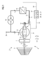
- the rotor 15 is provided with a symbolically represented rotor winding 17 in the illustrated here preferred embodiment of a generator 1, which is formed in the form of a three-phase winding and is characterized by the sign "3 ⁇ ". That is, the rotor winding is designed to generate a rotary field flux of the generator 11 with the rotor variable rotor rotational field frequency f 2 . Similar to the generation of three-phase current, a kind of "coil arrangement" can be made in the rotor winding 17, which generates a magnetic rotating field (exciter field) rotating at a rotor rotational field frequency f 2 when the current and / or voltage are applied accordingly to the rotor 15.
- stator rotary field frequency f 1 a field magnetization of the generator 11, which has a stator rotary field frequency f 1 relative to the stator 13.
- the stator rotary field frequency suitably agrees with the constant or variable predetermined network frequency.
- the drive 3 and the generator 11 can interpret independently of each other particularly appropriate.
- variable mains frequency the stator rotary field frequency can be tracked.
- a correspondingly made electrical loading of the rotor winding 17 is performed by a frequency converter 19 which is electrically connected for this purpose via an electrical connection and a slip ring connection 14 with the rotor winding 17.
- the slip ring terminal 14 and the electrical connection 21 is, as shown in FIG 1 by three slashes designed for three strands of running as a three-phase winding rotor winding 17 for three phases.
- the electric power can f by the frequency converter at a frequency 2 of the rotor rotary field frequency variable rotor rotary field frequency f 2 are provided.
- the power is obtained by the frequency converter 19 from the network, not shown.
- the frequency converter 19 via a transformer 23 to a network connection 25 connected.
- the mains frequency corresponds to the stator rotary field frequency f 1 , so that the frequency converter 19 performs a conversion from the mains frequency f 1 to the rotor rotary field frequency f 2 .
- the conversion takes place in the embodiment shown here only at the voltage level of the rotor winding, in the present case at 500 V.
- the power output of the stator 13 is at a voltage level of 10 kV, which corresponds to the mains voltage. According to the new concept, in the particularly preferred embodiment of a generator 1 shown in FIG. 1, therefore, only one frequency conversion at the voltage level of the rotor (500 V) is to be carried out.
- a transformer 23 adopts the voltage transformation necessary for this embodiment, from mains voltage at 10 kV to rotor voltage at 500 V, and is connected for this purpose between the mains connection 25 and the frequency converter 19.
- the frequency converter 19 preferably has an input converter, an energy storage intermediate circuit and an output converter for frequency conversion.
- the energy storage intermediate circuit may preferably be formed in the form of a capacitor or a choke coil.
- the frequency converter 19 also has means for field-oriented loading of the rotor winding 17.
- the frequency converter 19 corresponding semiconductor valves, which provide for a phase-correct loading of a corresponding strand, the rotor winding 17 designed as a three-phase winding.
- the present generator thus provides a variable electrical loading of the rotor winding 17 through the frequency converter 19 in such a way that with variable rotational frequency n of the rotor 15 and variable rotor rotational field frequency f 2 to the rotor 15, a predetermined and in the present case substantially constant stator rotational field frequency f 1 is present.
- the predetermined or predetermined stator rotational field frequency f 1 in particular in the case of smaller networks, also be transient or slightly transient.
- the stator rotary field frequency f 1 thus represents a comparatively constant control reference variable.
- a variable electric actuation of the rotor winding 17 predetermined by a control has been calculated with a controller 27 designed for this purpose.
- the measured values are transmitted via a control connection 33 at least from the stator and, if required, also from the rotor 15 to the control 27.
- the controller 27 has a computing unit 35 for a simulation of the generator 11. Under simulation of all magnetic fluxes occurring in the generator 11 according to a differential equation model designed for this purpose, a control signal (not shown) is provided in the output 37 of the controller 27, which is transmitted to the frequency converter 19 via a further control connection 39.
- an above-described field-oriented application of the rotor winding 17 takes place such that, given a variable rotational frequency n of the rotor 15 and variable rotor rotational field frequency f 2, a predetermined stator rotational field frequency f 1 is present.
- this generator 1 can advantageously be used to generate high voltages in the range of 10 kV, the voltages at the rotor winding being comparatively small (500 V). So it can be created with varying voltage, for example, a test field with a relatively low power.
- the use of the generator 1 is also suitable as Lastspitzenaggregat or as Einzelelnetzversorgeraggregat.
- the flywheel 7 is advantageous as part of the drive 3 as an energy buffer.
- the power of the otherwise suitable for higher power generator may well be below 10 MW, for example, in order to feed an island grid in the context of a decentralized supply.
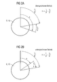
- variable rotor rotary field frequency f 1 rotary field magnetomotive force produced provided generator 11 an air gap between rotor and stator is found to be advantageous to the far above an air gap of conventional induction machines is, on the other hand is below air gaps conventional synchronous machines.
- a width of such an air gap between the rotor and stator is advantageously between 1 cm and 8 cm.
- an air gap between 2 cm and 4 cm takes into account the design of the generator 1 for a rotor voltage of 500 V and a stator voltage of 10 kV at a corresponding rotor rotational field frequency f 2 and a stator rotary field frequency f 1 .
- a generator 1 comprising a drive 3, a generator 11 with a stator 13 and a rotor 15 and a frequency converter 19
- the drive 3 for rotation of Rotor 15 is designed with variable rotational frequency n
- the rotor 15 has a rotor winding 17 which is designed to generate a rotary field flux of the generator 11 with the rotor 15 variable rotor rotational field frequency f 2
- the frequency converter 19 is electrically connected to the rotor winding 17
- a controller 27 is provided, comprising a recording 29 for measured values from the generator 11, a generator 35 for a generator simulation and an output 37 for a control signal to the frequency converter 19; wherein due to the control signal, an electrical loading of the rotor winding 17 by the frequency converter 19 can be effected such that at variable rotational frequency n of the rotor 15 and at a variable rotor rotational field frequency f 2 a predetermined
Landscapes
- Engineering & Computer Science (AREA)
- Power Engineering (AREA)
- Control Of Eletrric Generators (AREA)
- Synchronous Machinery (AREA)
- General Induction Heating (AREA)
- Control Of Motors That Do Not Use Commutators (AREA)
- Emergency Protection Circuit Devices (AREA)
- Paper (AREA)
- Oscillators With Electromechanical Resonators (AREA)
Priority Applications (8)
| Application Number | Priority Date | Filing Date | Title |
|---|---|---|---|
| EP05000257A EP1679787A1 (fr) | 2005-01-07 | 2005-01-07 | Groupe electrogene et procédé pour génération d'un courant de fréquence de sécteur prédeterminé |
| PCT/EP2005/055882 WO2006072498A1 (fr) | 2005-01-07 | 2005-11-10 | Groupe electrogene et procede de production de courant a une frequence reseau definie |
| EP05803005A EP1834404B1 (fr) | 2005-01-07 | 2005-11-10 | Groupe electrogene et procede de production de courant a une frequence reseau definie |
| CNB2005800462368A CN100574089C (zh) | 2005-01-07 | 2005-11-10 | 用于产生预定电网频率的电流的发电机组和方法 |
| US11/794,791 US7868594B2 (en) | 2005-01-07 | 2005-11-10 | Generating unit and method for producing a current with a predetermined network frequency |
| DE502005010778T DE502005010778D1 (de) | 2005-01-07 | 2005-11-10 | Stromaggregat und verfahren zur erzeugung von strom einer vorbestimmten netzfrequenz |
| AT05803005T ATE493791T1 (de) | 2005-01-07 | 2005-11-10 | Stromaggregat und verfahren zur erzeugung von strom einer vorbestimmten netzfrequenz |
| PL05803005T PL1834404T3 (pl) | 2005-01-07 | 2005-11-10 | Agregat prądotwórczy i sposób wytwarzania prądu o zadanej częstotliwości sieciowej |
Applications Claiming Priority (1)
| Application Number | Priority Date | Filing Date | Title |
|---|---|---|---|
| EP05000257A EP1679787A1 (fr) | 2005-01-07 | 2005-01-07 | Groupe electrogene et procédé pour génération d'un courant de fréquence de sécteur prédeterminé |
Publications (1)
| Publication Number | Publication Date |
|---|---|
| EP1679787A1 true EP1679787A1 (fr) | 2006-07-12 |
Family
ID=34933220
Family Applications (2)
| Application Number | Title | Priority Date | Filing Date |
|---|---|---|---|
| EP05000257A Withdrawn EP1679787A1 (fr) | 2005-01-07 | 2005-01-07 | Groupe electrogene et procédé pour génération d'un courant de fréquence de sécteur prédeterminé |
| EP05803005A Revoked EP1834404B1 (fr) | 2005-01-07 | 2005-11-10 | Groupe electrogene et procede de production de courant a une frequence reseau definie |
Family Applications After (1)
| Application Number | Title | Priority Date | Filing Date |
|---|---|---|---|
| EP05803005A Revoked EP1834404B1 (fr) | 2005-01-07 | 2005-11-10 | Groupe electrogene et procede de production de courant a une frequence reseau definie |
Country Status (7)
| Country | Link |
|---|---|
| US (1) | US7868594B2 (fr) |
| EP (2) | EP1679787A1 (fr) |
| CN (1) | CN100574089C (fr) |
| AT (1) | ATE493791T1 (fr) |
| DE (1) | DE502005010778D1 (fr) |
| PL (1) | PL1834404T3 (fr) |
| WO (1) | WO2006072498A1 (fr) |
Cited By (1)
| Publication number | Priority date | Publication date | Assignee | Title |
|---|---|---|---|---|
| EP3349350A1 (fr) * | 2017-01-11 | 2018-07-18 | Siemens Aktiengesellschaft | Procédé de fonctionnement d'une machine asynchrone en mode générateur |
Families Citing this family (7)
| Publication number | Priority date | Publication date | Assignee | Title |
|---|---|---|---|---|
| WO2008098891A1 (fr) | 2007-02-14 | 2008-08-21 | Alstom Technology Ltd | Centrale électrique et procédé de fonctionnement |
| GB0810400D0 (en) * | 2008-06-09 | 2008-07-09 | Rolls Royce Plc | A synchronous electrical machine |
| EP2136035A1 (fr) * | 2008-06-16 | 2009-12-23 | Siemens Aktiengesellschaft | Fonctionnement d'une installation à turbines à gaz et à vapeur par convertisseur de fréquence |
| CN101594113B (zh) * | 2009-04-13 | 2011-05-25 | 北京前沿科学研究所 | 可适应变化力矩的永磁风力发电机稳频控制系统 |
| CN102244498B (zh) * | 2011-03-11 | 2013-09-18 | 西门子公司 | 一种电网中的发电单元驱动器、发电单元以及能量输出设备 |
| US11101755B2 (en) | 2017-07-21 | 2021-08-24 | Siemens Aktiengesellschaft | Arrangement for injecting electric power into an AC network by means of an asynchronous machine, and method for operating the asynchronous machine |
| US11482956B2 (en) | 2017-12-05 | 2022-10-25 | Siemens Energy Global GmbH & Co. KG | Arrangement comprising an asynchronous machine and method for operating same |
Citations (1)
| Publication number | Priority date | Publication date | Assignee | Title |
|---|---|---|---|---|
| WO2004030199A2 (fr) * | 2002-09-24 | 2004-04-08 | Alexander Stoev | Systeme de generateur a generateur a couplage direct au reseau et procede pour maitriser des pannes de secteur |
Family Cites Families (18)
| Publication number | Priority date | Publication date | Assignee | Title |
|---|---|---|---|---|
| US2752515A (en) * | 1951-09-28 | 1956-06-26 | Westinghouse Electric Corp | Booster-fan rotor-ventilation |
| US3082337A (en) * | 1955-09-26 | 1963-03-19 | Parsons C A & Co Ltd | Dynamo-electric machines |
| GB1247344A (en) * | 1967-12-05 | 1971-09-22 | Nat Res Dev | Dynamo-electric machines |
| US3859578A (en) * | 1973-01-22 | 1975-01-07 | Mikhail Moiseevich Botvinnik | Method and circuit for controlling an asynchronized-synchronous machine |
| US4544874A (en) * | 1982-05-26 | 1985-10-01 | The Board Of Regents, The University Of Texas | Homopolar generator power supply system |
| JPS59129558A (ja) * | 1983-01-14 | 1984-07-25 | Hitachi Ltd | 可変速回転電機 |
| BE898244A (fr) * | 1983-11-17 | 1984-03-16 | Wenkin Michel | Générateur ou moteur électrique en forme de disque, à induit bobiné, sans fer et à inducteur garni d'aimants permanents. |
| CA1273695A (fr) * | 1985-09-25 | 1990-09-04 | Eiji Haraguchi | Systeme regulateur pour turbogenerateur hydraulique a regime variable |
| JP2585233B2 (ja) * | 1986-10-17 | 1997-02-26 | 株式会社日立製作所 | 可変速水車発電装置 |
| DE3855290T2 (de) * | 1987-08-14 | 1996-11-21 | Hitachi Ltd | Kontrollsystem für eine Hydrokraftanlage mit veränderlicher Geschwindigkeit |
| JP3144451B2 (ja) * | 1993-12-24 | 2001-03-12 | 株式会社日立製作所 | 可変速揚水発電装置 |
| DE19533950A1 (de) * | 1995-09-14 | 1997-03-20 | Guenter Fella | Generator mit Ausgangsspannung konstanter Frequenz |
| RU2224352C2 (ru) * | 1996-12-03 | 2004-02-20 | Эллиотт Энерджи Системс, Инк. | Электрическая система для турбины/генератора переменного тока на общем валу |
| ATE342603T1 (de) * | 2001-08-30 | 2006-11-15 | Siemens Ag | Schockfeste elektrische schiffsmaschine, z.b. motor oder generator |
| DE10232423A1 (de) * | 2002-07-17 | 2004-01-29 | Ge Wind Energy Gmbh | Verfahren zum Betreiben einer Windenergieanlage und Windenergieanlage zum Ausführen derartiger Verfahren |
| EP1540811B1 (fr) * | 2002-09-10 | 2010-12-01 | DeWind Co. | Procede d'utilisation d'une installation eolienne comportant une cascade hypersynchrone |
| ES2276170T5 (es) * | 2003-08-07 | 2020-02-25 | Vestas Wind Sys As | Método de control de una turbina eólica conectada a una red eléctrica pública durante una avería en dicha red eléctrica pública, sistema de control, turbina eólica y familia de los mismos |
| US7554302B2 (en) * | 2005-09-16 | 2009-06-30 | Satcon Technology Corporation | Slip-controlled, wound-rotor induction machine for wind turbine and other applications |
-
2005
- 2005-01-07 EP EP05000257A patent/EP1679787A1/fr not_active Withdrawn
- 2005-11-10 PL PL05803005T patent/PL1834404T3/pl unknown
- 2005-11-10 EP EP05803005A patent/EP1834404B1/fr not_active Revoked
- 2005-11-10 WO PCT/EP2005/055882 patent/WO2006072498A1/fr active Application Filing
- 2005-11-10 US US11/794,791 patent/US7868594B2/en not_active Expired - Fee Related
- 2005-11-10 AT AT05803005T patent/ATE493791T1/de active
- 2005-11-10 CN CNB2005800462368A patent/CN100574089C/zh not_active Expired - Fee Related
- 2005-11-10 DE DE502005010778T patent/DE502005010778D1/de active Active
Patent Citations (1)
| Publication number | Priority date | Publication date | Assignee | Title |
|---|---|---|---|---|
| WO2004030199A2 (fr) * | 2002-09-24 | 2004-04-08 | Alexander Stoev | Systeme de generateur a generateur a couplage direct au reseau et procede pour maitriser des pannes de secteur |
Cited By (1)
| Publication number | Priority date | Publication date | Assignee | Title |
|---|---|---|---|---|
| EP3349350A1 (fr) * | 2017-01-11 | 2018-07-18 | Siemens Aktiengesellschaft | Procédé de fonctionnement d'une machine asynchrone en mode générateur |
Also Published As
| Publication number | Publication date |
|---|---|
| EP1834404A1 (fr) | 2007-09-19 |
| PL1834404T3 (pl) | 2011-05-31 |
| EP1834404B1 (fr) | 2010-12-29 |
| CN100574089C (zh) | 2009-12-23 |
| US20080303279A1 (en) | 2008-12-11 |
| ATE493791T1 (de) | 2011-01-15 |
| WO2006072498A1 (fr) | 2006-07-13 |
| CN101099291A (zh) | 2008-01-02 |
| DE502005010778D1 (de) | 2011-02-10 |
| US7868594B2 (en) | 2011-01-11 |
Similar Documents
| Publication | Publication Date | Title |
|---|---|---|
| EP1834404B1 (fr) | Groupe electrogene et procede de production de courant a une frequence reseau definie | |
| EP1012943B1 (fr) | Systeme d'alimentation en energie electrique de consommateurs a moteur electrique | |
| DE69835757T2 (de) | Verfahren und vorrichtung zur kompensation eines synchrongenerators mit sektoren | |
| EP0995257A1 (fr) | Alternateur synchrone a utiliser dans des installations eoliennes, et une telle installation eolienne | |
| EP2465192A2 (fr) | Système générateur asynchrone et éolienne à système générateur asynchrone | |
| DE102013102900A1 (de) | Synchronmaschine | |
| EP1266446B1 (fr) | Generateur synchrone | |
| EP1504523B1 (fr) | Procede et dispositif de reglage limite par capteur d'une machine synchrone a excitation par aimant permanent | |
| EP1379780B1 (fr) | Procede d'utilisation d'une installation a energie eolienne | |
| DE102011076999A1 (de) | Verfahren zum Betreiben einer elektrischen Maschine in einem Kraftfahrzeug | |
| DE10051621C2 (de) | Polumschaltbarer Induktionsmotor | |
| EP2771663B1 (fr) | Dispositif de contrôle et procédé de contrôle d'une première et/ou d'une seconde machine électrique | |
| EP1548278B1 (fr) | Installation éolienne avec un dispositif de commande autoalimenté avec un module de régulation de puissance active et puissance réactive | |
| EP1995456B1 (fr) | Commutation électrique destinée à tester un châssis, en particulier d'une éolienne | |
| WO2009127508A2 (fr) | Machine électrique d'entraînement | |
| DE202023100266U1 (de) | Dynamisch rekonfigurierbare Synchronmotoren und Generatoren | |
| EP1758229B1 (fr) | Moteur électrique | |
| DE102011001513A1 (de) | Verfahren zur Steuerung oder Regelung einer rotierenden elektrischen Maschine und rotierende elektrische Maschine | |
| DE69314494T2 (de) | Von einer energiequelle angetriebener rotierender wechselstromgenerator zur erzeugung von elektrischer leistung | |
| DE3138894A1 (de) | Vorrichutng zum speisen eines verbrauchers mit einer gesicherten spannung vorgegebener frequenz | |
| DE102021004713A1 (de) | Phasen-Moment-Maschine | |
| EP1293033B1 (fr) | Commande et regulation de moteurs electriques | |
| EP0843912B1 (fr) | Procede et dispositif d'actionnement d'un moteur asynchrone | |
| DE10327221A1 (de) | Elektromotor | |
| DE966903C (de) | Elektrisches Getriebe |
Legal Events
| Date | Code | Title | Description |
|---|---|---|---|
| PUAI | Public reference made under article 153(3) epc to a published international application that has entered the european phase |
Free format text: ORIGINAL CODE: 0009012 |
|
| AK | Designated contracting states |
Kind code of ref document: A1 Designated state(s): AT BE BG CH CY CZ DE DK EE ES FI FR GB GR HU IE IS IT LI LT LU MC NL PL PT RO SE SI SK TR |
|
| AX | Request for extension of the european patent |
Extension state: AL BA HR LV MK YU |
|
| AKX | Designation fees paid | ||
| STAA | Information on the status of an ep patent application or granted ep patent |
Free format text: STATUS: THE APPLICATION IS DEEMED TO BE WITHDRAWN |
|
| 18D | Application deemed to be withdrawn |
Effective date: 20070112 |
|
| REG | Reference to a national code |
Ref country code: DE Ref legal event code: 8566 |