EP1679279A1 - Aufzugsanlage mit einer Steuervorrichtung - Google Patents
Aufzugsanlage mit einer Steuervorrichtung Download PDFInfo
- Publication number
- EP1679279A1 EP1679279A1 EP05000289A EP05000289A EP1679279A1 EP 1679279 A1 EP1679279 A1 EP 1679279A1 EP 05000289 A EP05000289 A EP 05000289A EP 05000289 A EP05000289 A EP 05000289A EP 1679279 A1 EP1679279 A1 EP 1679279A1
- Authority
- EP
- European Patent Office
- Prior art keywords
- elevator
- speed
- elevator car
- car
- deceleration
- Prior art date
- Legal status (The legal status is an assumption and is not a legal conclusion. Google has not performed a legal analysis and makes no representation as to the accuracy of the status listed.)
- Granted
Links
Images


Classifications
-
- B—PERFORMING OPERATIONS; TRANSPORTING
- B66—HOISTING; LIFTING; HAULING
- B66B—ELEVATORS; ESCALATORS OR MOVING WALKWAYS
- B66B5/00—Applications of checking, fault-correcting, or safety devices in elevators
- B66B5/02—Applications of checking, fault-correcting, or safety devices in elevators responsive to abnormal operating conditions
- B66B5/04—Applications of checking, fault-correcting, or safety devices in elevators responsive to abnormal operating conditions for detecting excessive speed
- B66B5/06—Applications of checking, fault-correcting, or safety devices in elevators responsive to abnormal operating conditions for detecting excessive speed electrical
-
- B—PERFORMING OPERATIONS; TRANSPORTING
- B66—HOISTING; LIFTING; HAULING
- B66B—ELEVATORS; ESCALATORS OR MOVING WALKWAYS
- B66B1/00—Control systems of elevators in general
- B66B1/24—Control systems with regulation, i.e. with retroactive action, for influencing travelling speed, acceleration, or deceleration
- B66B1/28—Control systems with regulation, i.e. with retroactive action, for influencing travelling speed, acceleration, or deceleration electrical
- B66B1/32—Control systems with regulation, i.e. with retroactive action, for influencing travelling speed, acceleration, or deceleration electrical effective on braking devices, e.g. acting on electrically controlled brakes
-
- B—PERFORMING OPERATIONS; TRANSPORTING
- B66—HOISTING; LIFTING; HAULING
- B66B—ELEVATORS; ESCALATORS OR MOVING WALKWAYS
- B66B5/00—Applications of checking, fault-correcting, or safety devices in elevators
- B66B5/02—Applications of checking, fault-correcting, or safety devices in elevators responsive to abnormal operating conditions
- B66B5/16—Braking or catch devices operating between cars, cages, or skips and fixed guide elements or surfaces in hoistway or well
Definitions
- the present invention relates to an elevator system and a control device for an elevator system.
- Lift systems comprise an elevator car which can be moved in an elevator shaft.
- Buffers are usually installed as safety devices in a shaft pit of the hoistway in order to decelerate the elevator car when the drive is malfunctioning when it passes the lowest station (or the counterweight when the uppermost station is passed over).
- Elevators with high rated speeds require very large buffers, which in turn requires a deep (and costly) pit. This complies with safety regulations which stipulate that the lift installation must be designed and constructed in such a way as to avoid a collision of the car in the shaft pit (see, for example, the European safety standard EN81).
- delay control circuits In order to be able to make the buffers and thus the shaft pit smaller, delay control circuits have already been proposed, which enable the use of smaller one-way buffer devices, as described, for example, in DE 201 04 389 U1 and DE 102 10 631 A1.
- EP 0 712 804 B1 discloses an overspeed detector with a plurality of light barriers arranged on the elevator car.
- the photoelectric sensors generate by means of a mounted on one side of the elevator shaft measuring bar Measured values by means of which the speed or deceleration of the elevator car can be determined.
- the measuring strip is redundant and consists of a marking track and a control track.
- a catching device which in particular comprises slips (compare DE 299 12 544 U1).
- the present invention seeks to provide an elevator system in which the buffer device and thus the pit can be further reduced or in which can be completely dispensed with a buffer device.
- the elevator system according to the invention or the control device according to the invention open as a secure two-stage electronic system, the possibility to waive a safety buffer completely or partially (with a partial waiver of the buffer, the provision of a smaller buffer, eg. A cheap disposable buffer made of polyurethane, only for conceivable extreme cases).
- a smaller buffer eg. A cheap disposable buffer made of polyurethane, only for conceivable extreme cases.
- the invention essentially comprises three components, namely a detection system for determining the absolute position of the elevator car, a delay control circuit for detecting signals for determining the speed or the delay of the elevator car as well as a third component an evaluation circuit for processing the signals supplied by the other two components.
- a detection system for determining the absolute position of the elevator car
- a delay control circuit for detecting signals for determining the speed or the delay of the elevator car
- an evaluation circuit for processing the signals supplied by the other two components.
- the invention can be used whenever the distance of an elevator car to an object below or above it has to be maintained. This will be in the most common application, the pit or the shaft ceiling of the elevator shaft, but it can also be a driving in the same elevator shaft under the elevator car second elevator car (so-called TWIN® system of the Applicant).
- the system according to the invention essentially comprises three components.
- the first of these components is a detection system for detecting signals for determining an absolute position of the elevator car.
- a detection system may, for example, operate on the basis of a magnetic tape having a plurality of pole pitches arranged in a non-repeating pattern.
- Such magnetic tapes are known per se and described, for example, in DE 197 32 713 A1 and DE 102 34 744 A1.
- Applicant of the present application also describes in German Patent Application Serial No. 10 2004 037 486.4 (incorporated herein by reference) a double signal band for determining a state of motion of a moving body.
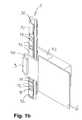
- FIGS. 1a and 1b Such a magnetic tape 90 suitable for carrying out the invention is shown in FIGS. 1a and 1b.
- the magnetic tape 90 comprises a plurality of pole pitches 92, 94 arranged in a non-repeating and thus unique pattern.
- a magnetic sensor 9, for example, a Hall sensor is arranged on the elevator car 6, not shown, and "reads" without contact that Pattern of the magnetic tape 90, which is fixed in the elevator shaft, for example. In a throat of the (not shown) elevator rails attached. From the signals supplied by the magnetic sensor 9, in addition to the absolute position, the speed of the elevator car 6 can be additionally derived.
- there are other methods known to those skilled in the art to determine the absolute position of an elevator car that may be used in this invention such as a laser measuring system operating on the principle of a bar code acquisition system.
- FIGS. 2 a and 2 b show an arrangement which is used for detecting signals for determining the speed or the deceleration of an elevator car for the control circuit.
- This arrangement comprises a band 70 on which a sensor-detectable pattern 72, 74 is applied.
- the belt is stationary in the elevator shaft in the region of the delay line of the elevator car 6 above the shaft pit (or below the shaft ceiling, since the invention is equally applicable to the security area at the upper shaft end).
- the pattern of the alternating sensor-sensitive measuring sections 72, 74 on the belt 70 is chosen such that a constant time value results from the detected signals, i. the individual measuring section sections 72, 74 become steadily shorter towards the lower end of the elevator shaft. An improper deceleration of the elevator car can thus be detected by means of an evaluation simply by a deviation from the constant desired time value.
- the belt 70 for detecting signals for determining the speed or the deceleration of an elevator car can be based on different, known in the art Realize types, for example. By means of a punched holes provided with metal strip whose pattern is picked up by a fork light barrier, or by magnetic pole divisions or optical reflection sections.
- the two measuring bands 70, 90 for the two described components can be applied to the front and rear sides of a carrier 1, for example the throat of an elevator rail, and the respective sensors 7, 9 for the two bands 70, 90 may be arranged on the legs 40, 42 of a U-shaped element on the elevator car, wherein the legs 40, 42 embrace the carrier 1 of the bands 70, 90 and so a simultaneous reading of the bands 70, 90 allow by the respective associated sensors 7, 9.
- the third component is an evaluation circuit 30, as shown by way of example in FIG.
- the evaluation circuit 30 can be realized by means of a micro-controller 10 which is electrically connected to the braking device and the catching device.
- the evaluation circuit 30 represents the core of a control device according to the invention.
- a safety relay device in the form of a first safety relay 11 and a second safety relay 12, a brake device (not shown) and an actuator 13 connected to the first safety relay 11, which actuates a catching device 14.
- double signal band 1 the two measuring bands, which for the sake of simplicity are referred to below as double signal band 1, are shown in highly schematic form together with the sensor units 7 to 9, wherein the sensor units 7 to 9 are attached to the outside of the elevator car as already mentioned are and are moved past the double signal band 1 in the driving operation of the elevator car.
- a third sensor 8 for detecting the speed and the position of the car can be provided in a further embodiment of the invention.
- a "2 of 3 selection" is possible and it is avoided that possibly briefly occurring interference signals, for example.
- the electrical output signals S 1 to S 3 of the sensors 7, 8, 9 are fed into the microcontroller 10.
- the microcontroller 10 has a first channel A and a second channel B.
- an elevator controller 31 can be provided (shown on the right in FIG. 3), which is separately connected to the microcontroller 10 and the first and second safety relays 11, 12.
- the first safety relay 11 and the second safety relay 12 are respectively connected to the first channel A and to the second channel B of the micro-controller 10.
- the first safety relay 11 is coupled to the actuator 13, which actuates the catching device 14 and can trigger it.
- the second safety relay 12 acts on the (not shown) braking device and can trigger the brake device at a corresponding control signal.
- Each of the channels A and B respectively comprises three input modules 15 to 17, to which the electrical signals S1 to S3 of the respective sensor devices 7 to 9 are applied.
- these two channels are designed with a different hardware, eg. By means of two different processors.
- Each channel of the microcontroller 10 may comprise a RAM 21, a flash memory 22, an EEPROM 23, an OSC watchdog 24, a CAN module and individual separate input modules 15 to 17.
- the hardware structure of the microcontroller 10 corresponds to a commercially available electronic component, as it is industrially available, so that its structure and the internal calculation process is not further explained in the further.
- the electrical signals of the two sensor devices 7 and 8 for detecting the speed are respectively applied to the modules 15 and 16 of a respective channel A, B. Subsequently, a corresponding billing of the signals applied to the modules is carried out, from which the actual speed of the car 6 can be determined.
- the determination of the actual speed is limited to a simple measurement of the time required to travel through a measuring section. If this time remains below a reference time permanently stored in channels A and B, then the speed is in the safe range. Due to the different length of the measuring sections, which are getting longer towards the shaft end, also a direct assignment to the position of the car is inevitably guaranteed.
- Each of the channels A and B further includes an interface 17, which may be formed as a parallel or serial input.
- the sensor 9 connected to these inputs supplies absolute position information as well as further speed information of the elevator car in the elevator shaft.
- a reference speed is stored for each position in the region of the delay paths, which was stored during commissioning of the elevator system by a teach-in procedure. These reference speed values are thus dependent on the set delay and the jerk of the respective elevator installation. In the case of a simple standard system, these values can also be permanently programmed on delivery.
- This stored reference speed is compared in the deceleration area at each new position of the car supplied by the sensors 7 to 9 with the actual speed traveled, measured by the sensors 7 to 9. If a fixed or adjustable tolerance threshold of the actually driven speed is exceeded, then first the second safety relay 12 is actuated, which leads in consequence to the engagement of the service brake.
- the first safety relay 11 When a second tolerance threshold is exceeded, for example when the brake device would fail, the first safety relay 11 is actuated beyond that actuates the safety gear of the elevator system in succession by triggering the actuator.
- All reference values are stored in a secure memory area and are continuously monitored for validity according to known memory test methods.
- the first channel A and the second channel B can be continuously compared with each other, so that differences in the electrical signals of the sensor devices 7 to 9 due to a comparison of the computational variables of the first channel A and the second channel B, respectively Errors are based, be recognized as soon as possible.
- the first safety relay 11 and the second safety relay 12 are operated for safety reasons, each with separate circuits.
- a plurality of safety relays can be connected, which are operated analogously with each separate circuits.
- the respective safety relays 11, 12 are electrically connected to the individual channels A, B of the microcontroller 10, so that control signals as will be explained below can be applied by the channels A, B to the corresponding safety relays 11, 12, and that in In return, a feedback information from the safety relay 11, 12 can be sent to the micro-controller 10.
- the first safety relay 11 is, as explained above, coupled to the actuator 13, which actuates the catching device 14.
- the catching device 14 may be a known wedge device that is driven to shut down the car in an emergency between a guide rail of the elevator system and an edge region of the elevator car.
- the actuator can also be activated and deactivated for test purposes by an electrical signal. After completion of the test operation, the normal driving operation of the elevator system can be resumed.
- the above-described device ensures by means of the double signal band 1 and the cooperating magnetic (alternatively optical) and electrical components effective speed limit or speed control of the elevator car.
- the apparatus may thus include conventional mechanical safety systems for speed limiting, i. Safety buffer, replace a lift.
- conventional electrical delay control circuits which are typically used in combination with oil buffers in higher speed elevator installations, can be replaced with the safe detection of deceleration according to the present invention.
- the device fulfills the provisions of the elevator directive on the basis of the safety concept explained above.
Abstract
Description
- Die vorliegende Erfindung betrifft eine Aufzuganlage sowie eine Steuervorrichtung für eine Aufzuganlage.
- Aufzuganlagen umfassen eine in einem Aufzugschacht verfahrbare Aufzugkabine. Als Sicherheitseinrichtungen werden üblicherweise Puffer in eine Schachtgrube des Aufzugschachts eingebaut, um bei Fehlfunktionen des Antriebs die Aufzugkabine bei Überfahren der untersten Haltestelle (oder das Gegengewicht bei Überfahren der obersten Haltestelle) definiert abzubremsen. Bei Aufzügen mit hohen Nenngeschwindigkeiten werden dafür sehr große Puffer benötigt, was wiederum eine tiefe (und in der Bauausführung teure) Schachtgrube erforderlich macht. Damit werden Sicherheitsvorschriften erfüllt, die vorschreiben, dass die Aufzuganlage derart gestaltet und ausgeführt sein muss, dass ein Aufprall der Kabine in der Schachtgrube vermieden wird (vgl. bspw. die europäische Sicherheitsvorschrift EN81).
- Um die Puffer und somit die Schachtgrube kleiner gestalten zu können, wurden bereits Verzögerungskontrollschaltungen vorgeschlagen, die einen Einsatz von kleineren Einwegpuffereinrichtungen, wie sie bspw. in der DE 201 04 389 U1 und DE 102 10 631 A1 beschrieben sind, ermöglichen.
- Aus der EP 0 712 804 B1 ist ein Übergeschwindigkeitsdetektor mit mehreren an der Aufzugkabine angeordneten Lichtschranken bekannt. Die Lichtschranken erzeugen anhand einer an einer Seite des Aufzugschachtes befestigten Messleiste Messwerte, anhand derer die Geschwindigkeit bzw. Verzögerung der Aufzugkabine ermittelt werden kann. Die Messleiste ist dabei redundant ausgeführt und besteht aus einer Markierungsbahn und einer Kontrollbahn.
- Des weiteren ist es üblich und bekannt, für Notfälle zusätzlich zu der vorhandenen Bremseinrichtung der Aufzugkabine eine Fangeinrichtung vorzusehen, die insbesondere Fangkeile umfasst (vgl. DE 299 12 544 U1).
- Ausgehend hiervon liegt der Erfindung die Aufgabe zugrunde, eine Aufzuganlage zu schaffen, bei der die Puffereinrichtung und somit die Schachtgrube weiter verkleinert werden können bzw. bei der auf eine Puffereinrichtung vollständig verzichtet werden kann.
- Zur Lösung dieser Aufgabe wird eine Aufzuganlage mit den Merkmalen des Anspruchs 1 sowie eine Steuervorrichtung mit den Merkmalen des Anspruchs 10 vorgeschlagen.
- Die erfindungsgemäße Aufzuganlage bzw. die erfindungsgemäße Steuervorrichtung eröffnen als sicheres zweistufiges elektronisches System die Möglichkeit, auf einen Sicherheitspuffer vollständig oder teilweise zu verzichten (wobei unter einem teilweisen Verzicht auf den Puffer das Vorsehen eines kleineren Puffers, bspw. eines billigen Einwegpuffers aus Polyurethan, lediglich für denkbare Extremfälle zu verstehen ist). Somit kann mit dem erfindungsgemäßen System eine konsequente Weiterverkleinerung existierender Puffersysteme betrieben werden.
- Die Erfindung umfasst im wesentlichen drei Komponenten, nämlich ein Erfassungssystem zum Bestimmen der absoluten Position der Aufzugkabine, eine Verzögerungskontrollschaltung zum Erfassen von Signalen zum Bestimmen der Geschwindigkeit bzw. der Verzögerung der Aufzugkabine sowie als dritte Komponente eine Auswerteschaltung zur Verarbeitung der von den beiden anderen Komponenten gelieferten Signale. Dabei handelt es sich um ein sogenanntes redundantdiversitäres System.
- Die Erfindung kann immer dann eingesetzt werden, wenn der Abstand einer Aufzugkabine zu einem sich darunter oder darüber befindlichen Objekt einzuhalten ist. Dies wird in der häufigsten Anwendung die Schachtgrube bzw. die Schachtdecke des Aufzugschachtes sein, es kann sich dabei aber auch um eine in demselben Aufzugschacht unter der Aufzugkabine fahrende zweite Aufzugkabine handeln (sogenanntes TWIN® -System der Anmelderin).
- Weitere Vorteile und Ausgestaltungen der Erfindung ergeben sich aus der Beschreibung und der beiliegenden Zeichnung.
- Es versteht sich, dass die vorstehend genannten und die nachstehend noch zu erläuternden Merkmale nicht nur in der jeweils angegebenen Kombination, sondern auch in anderen Kombinationen oder in Alleinstellung verwendbar sind, ohne den Rahmen der vorliegenden Erfindung zu verlassen.
- Die Erfindung ist anhand eines Ausführungsbeispieles in der Zeichnung schematisch dargestellt und wird im folgenden unter Bezugnahme auf die Zeichnung ausführlich beschrieben.
- Figur 1a
- zeigt in Draufsicht eine Anordnung zum Erfassen von Signalen zum Bestimmen einer absoluten Position einer Aufzugkabine.
- Figur 1b
- zeigt die Anordnung der Figur 1b in perspektivischer Ansicht.
- Figur 2a
- zeigt in Draufsicht eine Anordnung zum Erfassen von Signalen zum Bestimmen der Geschwindigkeit bzw. der Verzögerung einer Aufzugkabine für eine Verzögerungskontrollschaltung.
- Figur 2b
- zeigt die Anordnung der Figur 2b in perspektivischer Ansicht.
- Figur 3
- zeigt ein Strukturdiagramm einer Auswerteschaltung.
- Wie bereits voranstehend erwähnt, umfasst das erfindungsgemäße System im wesentlichen drei Komponenten.
- Die erste dieser Komponenten ist ein Erfassungssystem zum Erfassen von Signalen zum Bestimmen einer absoluten Position der Aufzugkabine. Ein derartiges Erfassungssystem kann bspw. auf der Grundlage eines Magnetbandes mit einer Vielzahl von nach einem sich nicht wiederholenden Muster angeordneten Polteilungen funktionieren. Derartige Magnetbänder sind an sich bekannt und bspw. in der DE 197 32 713 A1 und der DE 102 34 744 A1 beschrieben. Die Anmelderin der vorliegenden Anmeldung beschreibt in der deutschen Patentanmeldung mit dem Aktenzeichen 10 2004 037 486.4 (die durch Bezugnahme hierin aufgenommen ist) ebenfalls ein Doppelsignalband zum Bestimmen eines Bewegungszustandes eines bewegten Körpers.
- Ein derartiges zur Ausführung der Erfindung geeignetes Magnetband 90 ist in den Figuren 1a und 1b dargestellt. Das Magnetband 90 umfasst eine Vielzahl von Polteilungen 92, 94, die nach einem sich nicht wiederholenden und somit eindeutigen Muster angeordnet sind. Ein magnetischer Sensor 9, bspw. ein Hall-Sensor ist an der nicht näher dargestellten Aufzugkabine 6 angeordnet und "liest" berührungslos das Muster des Magnetbandes 90, das ortsfest im Aufzugschacht, bspw. in einer Kehle der (nicht dargestellten) Aufzugschienen, angebracht ist. Aus den von dem magnetischen Sensor 9 gelieferten Signalen kann neben der absoluten Position ergänzend auch die Geschwindigkeit der Aufzugkabine 6 abgeleitet werden. Selbstverständlich gibt es noch andere dem Fachmann geläufige Methoden, die absolute Position einer Aufzugkabine zu bestimmen, die im Rahmen dieser Erfindung verwendet werden können, wie bspw. ein Laser-Messsystem das nach dem Prinzip eines Barcode-Erfassungssystems arbeitet.
- Die zweite der erwähnten Komponenten ist eine Kontrollschaltung. In den Figuren 2a und 2b ist eine Anordnung dargestellt, die zum Erfassen von Signalen zum Bestimmen der Geschwindigkeit bzw. der Verzögerung einer Aufzugkabine für die Kontrollschaltung dient. Diese Anordnung umfasst ein Band 70, auf dem ein von einem Sensor erfassbares Muster 72, 74 aufgebracht ist. Das Band ist ortsfest im Aufzugschacht im Bereich der Verzögerungsstrecke der Aufzugkabine 6 oberhalb der Schachtgrube (bzw. unterhalb der Schachtdecke, da die Erfindung in gleichem Maße für den Sicherheitsbereich am oberen Schachtende einsetzbar ist) angeordnet. Das Muster der sich abwechselnden sensorrelevanten Messstreckenabschnitte 72, 74 auf dem Band 70 ist derart gewählt, dass sich aus den erfassten Signalen ein konstanter Zeitwert ergibt, d.h. die einzelnen Messstreckenabschnitte 72, 74 werden zum unteren Ende des Aufzugschachtes hin stetig kürzer. Eine nicht ordnungsgemäße Verzögerung der Aufzugkabine lässt sich somit mittels einer Auswertung einfach durch eine Abweichung von dem konstanten Soll-Zeitwert erkennen.
- Das Band 70 zum Erfassen von Signalen zum Bestimmen der Geschwindigkeit bzw. der Verzögerung einer Aufzugkabine lässt sich auf unterschiedliche, dem Fachmann an sich bekannte Arten realisieren, bspw. mittels eines mit Stanzlöchern versehenen Metallbandes, dessen Muster durch eine Gabellichtschranke aufgenommen wird, oder durch magnetische Polteilungen oder optische Reflexionsabschnitte.
- Wie aus den perspektivischen Darstellungen der Figuren 1b und 2b erkennbar ist, können die beiden Messbänder 70, 90 für die beiden beschriebenen Komponenten auf Vorder- und Rückseite eines Trägers 1, bspw. der Kehle einer Aufzugschiene, aufgebracht sein, und die jeweiligen Sensoren 7, 9 für die beiden Bänder 70, 90 können an den Schenkeln 40, 42 eines U-förmigen Elements an der Aufzugkabine angeordnet sein, wobei die Schenkel 40, 42 den Träger 1 der Bänder 70, 90 umgreifen und so ein zeitgleiches Ablesen der Bänder 70, 90 durch die jeweils zugeordneten Sensoren 7, 9 gestatten.
- Die dritte Komponente ist eine Auswerteschaltung 30, wie sie beispielhaft in Figur 3 dargestellt ist. Die Auswerteschaltung 30 kann dabei mittels eines Mikro-Controllers 10 realisiert sein, der mit der Bremseinrichtung und der Fangeinrichtung elektrisch verbunden ist. Die Auswerteschaltung 30 stellt das Kernstück einer erfindungsgemäßen Steuervorrichtung dar.
- An dem Mikro-Controller 10 angeschlossen sind eine Sicherheitsrelaiseinrichtung in Form eines ersten Sicherheitsrelais 11 und eines zweiten Sicherheitsrelais 12, eine (nicht dargestellte) Bremseinrichtung und ein an dem ersten Sicherheitsrelais 11 angeschlossener Aktuator 13, der eine Fangeinrichtung 14 betätigt. Im linken Bereich der Figur 3 sind die beiden Messbänder, die im folgenden der Einfachheit halber kurz als Doppelsignalband 1 bezeichnet werden, stark schematisiert zusammen mit den Sensoreinrichtungen 7 bis 9 dargestellt, wobei die Sensoreinrichtungen 7 bis 9 wie bereits erwähnt außen an der Aufzugkabine angebracht sind und im Fahrtbetrieb der Aufzugkabine an dem Doppelsignalband 1 vorbeibewegt werden.
- Zur sicheren Erfassung der Geschwindigkeit sind an sich zwei redundant/diversitäre Sensoren 7 und 9 mit entsprechend zweikanaliger Auswertung ausreichend. Aus Gründen eines möglichst störungsfreien Betriebes der Aufzuganlage kann in weiterer Ausgestaltung der Erfindung ein dritter Sensor 8 zur Erfassung der Geschwindigkeit und der Position des Fahrkorbes vorgesehen sein. Somit ist eine "2 aus 3 Auswahl" möglich und es wird vermieden, dass eventuell kurzzeitig auftretende Störsignale, bspw. durch elektromagnetische Beeinflussungen, nicht sofort zum Stillstand der Anlage führen.
- Die elektrischen Ausgangssignale S1 bis S3 der Sensoren 7, 8, 9 werden in den Mikro-Controller 10 eingespeist. Der Mikro-Controller 10 weist einen ersten Kanal A und einen zweiten Kanal B auf. Des weiteren kann (in Figur 3 rechts gezeigt) eine Aufzugsteuerung 31 vorgesehen sein, die jeweils mit dem Mikro-Controller 10 und dem ersten und zweiten Sicherheitsrelais 11, 12 separat verbunden ist.
- Das erste Sicherheitsrelais 11 und das zweite Sicherheitsrelais 12 sind jeweils an den ersten Kanal A und an den zweiten Kanal B des Mikro-Controllers 10 angeschlossen. Das erste Sicherheitsrelais 11 ist mit dem Aktuator 13 gekoppelt, der die Fangeinrichtung 14 betätigt und diese auslösen kann. Das zweite Sicherheitsrelais 12 wirkt auf die (nicht gezeigte) Bremseinrichtung ein und kann bei einem entsprechenden Steuersignal die Bremseinrichtung auslösen.
- Jeder der Kanäle A und B umfasst jeweils drei Eingangsmodule 15 bis 17, an die die elektrischen Signale S1 bis S3 der jeweiligen Sensoreinrichtungen 7 bis 9 angelegt werden. Zur Erhöhung der Betriebssicherheit der Vorrichtung sind diese beiden Kanäle mit einer unterschiedlichen Hardware ausgestaltet, bspw. mittels zweier verschiedener Prozessoren. Jeweils jeder Kanal des Mikro-Controllers 10 kann einen RAM 21, ein Flash-Memory 22, einen EEPROM 23, einen OSC-Watchdog 24, ein CAN-Modul und einzelne separate Eingangsmodule 15 bis 17 umfassen. Der Hardware-Aufbau des Mikro-Controllers 10 entspricht einem handelsüblichen elektronischen Bauelement, wie es industriell verfügbar ist, so dass dessen Aufbau und der interne Rechenablauf im weiteren nicht näher erläutert ist.
- Die elektrischen Signale der zwei Sensoreinrichtungen 7 und 8 zur Erfassung der Geschwindigkeit werden jeweils an die Module 15 und 16 eines jeweiligen Kanals A, B angelegt. Anschließend wird eine entsprechende Verrechnung der an die Module angelegten Signale durchgeführt, woraus sich die Ist-Geschwindigkeit des Fahrkorbes 6 bestimmen lässt. Die Ermittlung der Ist-Geschwindigkeit beschränkt sich auf eine einfache Messung der Zeit die zum Durchfahren eines Messstreckenabschnittes benötigt wird. Bleibt diese Zeit unter einer in den Kanälen A und B fest abgespeicherten Referenzzeit, so ist die Geschwindigkeit im sicheren Bereich. Durch die unterschiedliche Länge der Messstreckenabschnitte, die zum Schachtende hin immer länger werden, ist ebenfalls eine direkte Zuordnung zur Position des Fahrkorbes zwangsläufig gewährleistet.
- Jeder der Kanäle A und B umfasst darüber hinaus eine Schnittstelle 17, die als paralleler oder serieller Eingang ausgebildet sein kann. Der an diese Eingänge angeschlossene Sensor 9 liefert eine absolute Positionsinformation sowie eine weitere Geschwindigkeitsinformation des Fahrkorbes im Aufzugschacht.
- In den jeweiligen Speicherbereichen der Kanäle A und B ist für jede Position im Bereich der Verzögerungswege eine Referenzgeschwindigkeit hinterlegt, die bei der Inbetriebnahme der Aufzuganlage durch ein Teach-in-Verfahren abgespeichert wurde. Diese Referenz-Geschwindigkeitswerte sind somit abhängig von der eingestellten Verzögerung und dem Ruck der jeweiligen Aufzuganlage. Bei einer einfachen Standardanlage können diese Werte auch bereits bei der Auslieferung fest einprogrammiert sein. Diese abgespeicherte Referenzgeschwindigkeit wird im Verzögerungsbereich an jeder durch die Sensoren 7 bis 9 gelieferten neuen Position des Fahrkorbes mit der tatsächlich gefahrenen Geschwindigkeit, gemessen durch die Sensoren 7 bis 9, verglichen. Wird eine feste oder einstellbare Toleranzschwelle der tatsächlich gefahrenen Geschwindigkeit überschritten, so wird zunächst das zweite Sicherheitsrelais 12 betätigt, das in Folge zum Einfallen der Betriebsbremse führt.
- Beim Überschreiten einer zweiten Toleranzschwelle, bspw. wenn die Bremseinrichtung versagen würde, wird darüber hinaus das erste Sicherheitsrelais 11 betätigt, das in Folge durch Auslösen des Aktuators die Fangvorrichtung der Aufzuganlage betätigt.
- Alle Referenzwerte sind in einem sicheren Speicherbereich abgelegt und werden nach an sich bekannten Speicher-Testverfahren laufend auf ihre Gültigkeit hin überwacht. Zur weiteren Erhöhung der Betriebssicherheit könnder erste Kanal A und der zweite Kanal B fortwährend miteinander verglichen werden, so dass aufgrund eines Vergleichs der Rechengrößen des ersten Kanals A bzw. des zweiten Kanals B Unterschiede der elektrischen Signale der Sensoreinrichtungen 7 bis 9, die bspw. auf Fehler beruhen, frühestmöglich erkannt werden.
- Das erste Sicherheitsrelais 11 und das zweite Sicherheitsrelais 12 werden aus Sicherheitsaspekten mit jeweils getrennten Stromkreisen betrieben. An jeden Kanal des Mikro-Controllers 10 können auch eine Mehrzahl von Sicherheitsrelais angeschlossen sein, die analog mit jeweils getrennten Stromkreisen betrieben werden. Die jeweiligen Sicherheitsrelais 11, 12 sind mit den einzelnen Kanälen A, B des Mikro-Controllers 10 elektrisch verbunden, so dass Steuersignale wie nachstehend noch zu erläutern von den Kanälen A, B an die entsprechenden Sicherheitsrelais 11, 12 angelegt werden können, und dass im Gegenzug eine Rückmeldeinformation von den Sicherheitsrelais 11, 12 an den Mikro-Controller 10 gesendet werden kann.
- Das erste Sicherheitsrelais 11 ist wie voranstehend erläutert mit dem Aktuator 13 gekoppelt, der die Fangeinrichtung 14 betätigt. Bei der Fangeinrichtung 14 kann es sich um eine an sich bekannte Keilvorrichtung handeln, die zum Stillsetzen des Fahrkorbs im Notfall zwischen eine Führungsschiene der Aufzuganlage und einen Randbereich des Fahrkorbes getrieben wird. Bei einem Stillstand des Fahrkorbes 6 kann der Aktuator auch für Testzwecke durch ein elektrisches Signal aktiviert und deaktiviert werden. Nach Beenden des Testbetriebs kann der normale Fahrbetrieb der Aufzuganlage wieder aufgenommen werden.
- Nach einem Auslösen der Bremseinrichtung durch ein Steuersignal des zweiten Sicherheitsrelais 12 oder der Fangeinrichtung 14 durch Steuersignal des ersten Sicherheitsrelais 11 ist ein weiterer Betrieb der erfindungsgemäßen Vorrichtung erst dann möglich, wenn eine Betriebsüberprüfung durch ein Fachpersonal stattgefunden hat. Nach erfolgter Überprüfung wird ein entsprechendes Freigabesignal von dem jeweiligen Sicherheitsrelais 11 bzw. 12 zurück an den entsprechenden Kanal A, B gesendet, woraufhin ein normaler Fahrtbetrieb der Aufzuganlage fortgesetzt werden kann.
- Die voranstehend erläuterte Vorrichtung gewährleistet mittels des Doppelsignalbandes 1 und der damit zusammenwirkenden magnetischen (alternativ optischen) und elektrischen Bauelemente eine wirksame Geschwindigkeitsbegrenzung bzw. Geschwindigkeitskontrolle des Aufzug-Fahrkorbes. Die Vorrichtung kann somit herkömmliche mechanische Sicherheitssysteme für eine Geschwindigkeitsbegrenzung, d.h. Sicherheitspuffer, eines Aufzuges ersetzen. Ebenso können herkömmliche elektrische Verzögerungskontrollschaltungen, die in der Regel in Kombination mit Ölpuffern bei Aufzuganlagen mit höheren Geschwindigkeiten eingesetzt werden, mit der erfindungsgemäßen sicheren Erfassung der Verzögerung ersetzt werden.
- Die Vorrichtung erfüllt aufgrund des voranstehend erläuterten Sicherheitskonzeptes die Bestimmungen der Aufzugrichtlinie.
Claims (7)
- Aufzuganlage mit einer in einem Aufzugschacht verfahrbaren Aufzugkabine (6) mit einer Bremseinrichtung und einer Fangelemente umfassenden Fangeinrichtung (14), wobei die Aufzuganlage des weiteren ein Erfassungssystem zum Erfassen von Signalen zum Bestimmen einer absoluten Position der Aufzugkabine, eine Kontrollschaltung zum Erfassen von Signalen zum Bestimmen der Geschwindigkeit bzw. Verzögerung der Aufzugkabine (6) sowie eine Auswerteschaltung (30) zum Auswerten der Signale des Erfassungssystems und der Kontrollschaltung umfasst, wobei die Auswerteschaltung (30) auf der Grundlage der Eingangssignale eine Auswertung trifft, ob die Geschwindigkeit der Aufzugkabine (6) an der ermittelten Position innerhalb eines Vorgabeintervalls liegt und abhängig vom Ergebnis der Auswertung über einen ersten Ausgang der Auswerteschaltung (30) die Betätigung der Bremseinrichtung und/oder über einen zweiten Ausgang der Auswerteschaltung die Auslösung der Fangeinrichtung veranlasst.
- Aufzuganlage nach Anspruch 1, bei der das Erfassungssystem ein in dem Aufzugschacht angeordnetes Messband (9) mit einem definierten, sich nicht wiederholenden Muster (92, 94) umfasst.
- Aufzuganlage nach Anspruch 2, bei der das Messband (9) ein Magnetband mit einem Polteilungsmuster (92, 94) ist.
- Aufzuganlage nach einem der Ansprüche 1 bis 3, bei der die Kontrollschaltung ein in dem Aufzugschacht angeordnetes Messband (7) mit einem definierten Muster (72, 74) umfasst, wobei die das Muster bildenden Messstreckenabschnitte (72, 74) zum Ende des Messbandes (7) hin kürzer werden.
- Aufzuganlage nach Anspruch 2 und 4, bei der die Bänder (7, 9) Vorder- und Rückseite eines Doppelsignalbandes (1) bilden.
- Steuervorrichtung zur Geschwindigkeitsbegrenzung einer Aufzugkabine (6) einer Aufzuganlage, die dazu ausgebildet ist, mit einer Bremseinrichtung und einer Fangelemente umfassenden Fangrichtung (14) der Aufzuganlage gekoppelt zu werden, wobei die Steuervorrichtung aus Eingangssignalen (S3) zum Bestimmen einer absoluten Position der Aufzugkabine (6) und aus Eingangssignalen (S1) zum Bestimmen der Geschwindigkeit bzw. Verzögerung der Aufzugkabine (6) Ort und Geschwindigkeit bzw. Verzögerung der Aufzugkabine (6) bestimmt und bei einer Abweichung von Sollwerten für das Parameterpaar Ort und Geschwindigkeit zunächst die Bremseinrichtung auslöst und, falls trotz Auslösen der Bremseinrichtung weiterhin eine Abweichung von Sollwerten für das Parameterpaar Ort und Geschwindigkeit vorliegt und sich die Aufzugkabine (6) innerhalb eines kritischen Bereiches befindet, anschließend die Fangeinrichtung (14) auslöst.
- Verfahren zum Steuern einer Aufzuganlage mit einer in einem Aufzugschacht verfahrbaren Aufzugkabine (6), mit den folgenden Schritten:- Erfassen einer absoluten Position der Aufzugkabine (6),- Erfassen einer Geschwindigkeit bzw. Verzögerung der Aufzugkabine (6) an der erfassten Position,- Vergleichen des erfassten Parameterpaares Ort und Geschwindigkeit/Verzögerung mit Sollwerten, und im Falle einer Abweichung des erfassten Parameterpaares von den Sollwerten um mehr als eine erlaubte Toleranz:- Auslösen einer Bremseinrichtung der Aufzuganlage,- Wiederholen der Schritte des Erfassens und des Vergleichens,- Auslösen einer Fangeinrichtung der Aufzuganlage, falls das Ergebnis des Vergleiches nach wie vor außerhalb eines Toleranzbereiches der Sollwerte liegt.
Priority Applications (8)
| Application Number | Priority Date | Filing Date | Title |
|---|---|---|---|
| DE502005001371T DE502005001371D1 (de) | 2005-01-07 | 2005-01-07 | Aufzugsanlage mit einer Steuervorrichtung |
| ES05000289T ES2293392T5 (es) | 2005-01-07 | 2005-01-07 | Ascensor con sistema de control. |
| AT05000289T ATE371624T1 (de) | 2005-01-07 | 2005-01-07 | Aufzugsanlage mit einer steuervorrichtung |
| EP05000289A EP1679279B2 (de) | 2005-01-07 | 2005-01-07 | Aufzugsanlage mit einer Steuervorrichtung |
| US11/813,504 US7946393B2 (en) | 2005-01-07 | 2005-12-27 | Safety evaluation and control system for elevator units |
| PCT/EP2005/014043 WO2006072428A2 (de) | 2005-01-07 | 2005-12-27 | Aufzuganlage mit einer steuervorrichtung |
| JP2007549821A JP4827854B2 (ja) | 2005-01-07 | 2005-12-27 | エレベータ・ユニット及びエレベータ・ユニット用の制御装置 |
| CN2005800458767A CN101094802B (zh) | 2005-01-07 | 2005-12-27 | 升降机、升降机的控制设备以及用于控制升降机的方法 |
Applications Claiming Priority (1)
| Application Number | Priority Date | Filing Date | Title |
|---|---|---|---|
| EP05000289A EP1679279B2 (de) | 2005-01-07 | 2005-01-07 | Aufzugsanlage mit einer Steuervorrichtung |
Publications (3)
| Publication Number | Publication Date |
|---|---|
| EP1679279A1 true EP1679279A1 (de) | 2006-07-12 |
| EP1679279B1 EP1679279B1 (de) | 2007-08-29 |
| EP1679279B2 EP1679279B2 (de) | 2011-03-30 |
Family
ID=34933226
Family Applications (1)
| Application Number | Title | Priority Date | Filing Date |
|---|---|---|---|
| EP05000289A Not-in-force EP1679279B2 (de) | 2005-01-07 | 2005-01-07 | Aufzugsanlage mit einer Steuervorrichtung |
Country Status (8)
| Country | Link |
|---|---|
| US (1) | US7946393B2 (de) |
| EP (1) | EP1679279B2 (de) |
| JP (1) | JP4827854B2 (de) |
| CN (1) | CN101094802B (de) |
| AT (1) | ATE371624T1 (de) |
| DE (1) | DE502005001371D1 (de) |
| ES (1) | ES2293392T5 (de) |
| WO (1) | WO2006072428A2 (de) |
Cited By (3)
| Publication number | Priority date | Publication date | Assignee | Title |
|---|---|---|---|---|
| EP2039642A1 (de) * | 2007-09-19 | 2009-03-25 | Mac Puar, S.A. | Auslösevorrichtung für die Endpositionen eines Aufzugs und Betriebsverfahren dieser Auslösevorrichtung |
| US8230977B2 (en) | 2007-08-07 | 2012-07-31 | Thyssenkrupp Elevator Ag | Distributed control system for an elevator system |
| WO2013057215A3 (de) * | 2011-10-18 | 2014-04-10 | Elgo Electronic Gmbh & Co. Kg | Vorrichtung zur positionserfassung einer aufzugkabine und verfahren zum betreiben einer aufzuganlage |
Families Citing this family (28)
| Publication number | Priority date | Publication date | Assignee | Title |
|---|---|---|---|---|
| JP4882820B2 (ja) * | 2007-03-26 | 2012-02-22 | 株式会社日立製作所 | エレベータ速度検出方法 |
| ES2343608B1 (es) | 2007-08-03 | 2011-06-16 | Orona, S.Coop | Procedimiento y dispositivo de actuacion en situacion de emergencia en aparatos elevadores. |
| JP2009084009A (ja) * | 2007-10-01 | 2009-04-23 | Hitachi Ltd | 移動体速度検出装置 |
| JP2009215046A (ja) * | 2008-03-12 | 2009-09-24 | Toshiba Elevator Co Ltd | エレベータの終端階強制減速装置 |
| EP2206672B1 (de) | 2009-01-07 | 2013-06-26 | K. A. Schmersal GmbH & Co. KG | Verfahren und Einrichtung zur Überwachung einer Aufzugskabine |
| FI121663B (fi) * | 2009-10-09 | 2011-02-28 | Kone Corp | Mittausjärjestely, valvontajärjestely sekä hissijärjestelmä |
| EP2516305B1 (de) * | 2009-12-22 | 2015-02-11 | Inventio AG | Verfahren und vorrichtung zur bestimmung der bewegung und/oder der position einer aufzugskabine |
| DE102009060321A1 (de) * | 2009-12-23 | 2011-06-30 | Liebherr-Werk Ehingen GmbH, 89584 | Steuersystem für Baumaschinen und Verfahren zum Betrieb des Steuersystems |
| EP2540651B1 (de) * | 2011-06-28 | 2013-12-18 | Cedes AG | Aufzugvorrichtung, Gebäude und Positionsbestimmungsvorrichtung |
| FR2984864A1 (fr) * | 2011-12-27 | 2013-06-28 | Arnoult Serge | Controle du mouvement d'une cabine d'ascenseur |
| CA2861399A1 (en) * | 2012-01-25 | 2013-08-01 | Inventio Ag | Method and control device for monitoring travel movements of a lift cage |
| DE102012106056A1 (de) | 2012-07-05 | 2014-01-09 | Rg Mechatronics Gmbh | Regelvorrichtung zum Regeln der Beschleunigung einer in vertikaler Richtung bewegten Transporteinrichtung |
| ES2666879T3 (es) * | 2012-11-29 | 2018-05-08 | Otis Elevator Company | Recuperación de posición por medio de modelos de rellanos ficticios |
| US9452909B2 (en) | 2013-10-25 | 2016-09-27 | Thyssenkrupp Elevator Ag | Safety related elevator serial communication technology |
| CN103601049B (zh) * | 2013-12-06 | 2016-01-20 | 北京金自天正智能控制股份有限公司 | 一种显示升降容器的位置状态的设备和方法 |
| DE112014006686B4 (de) * | 2014-05-21 | 2020-04-16 | Mitsubishi Electric Corp. | Aufzugspositions-Erfassungsvorrichtung |
| EP3436385A4 (de) | 2016-03-30 | 2019-12-18 | KONE Corporation | Verfahren, sicherheitssteuereinheit und aufzugsystem zur überprüfung von geschwindigkeitsdaten einer aufzugskabine zur überdrehzahlüberwachung der aufzugskabine |
| US10112803B2 (en) * | 2016-04-01 | 2018-10-30 | Otis Elevator Company | Protection assembly for elevator braking assembly speed sensing device and method |
| US20170283216A1 (en) * | 2016-04-01 | 2017-10-05 | Otis Elevator Company | Condition sensing arrangement for elevator system brake assembly and method |
| CN106348123B (zh) * | 2016-10-09 | 2019-04-26 | 上海中联重科电梯有限公司 | 防止电梯轿厢意外移动的系统及方法 |
| AU2018275606B2 (en) * | 2017-06-02 | 2021-05-20 | Inventio Ag | Floor position detection device of a lift installation and method for generating a floor signal |
| EP3434634B1 (de) | 2017-07-25 | 2021-01-06 | Otis Elevator Company | Sicherheitsvorrichtung für einen aufzug |
| US11591183B2 (en) | 2018-12-28 | 2023-02-28 | Otis Elevator Company | Enhancing elevator sensor operation for improved maintenance |
| CN110761624B (zh) * | 2019-09-18 | 2020-12-04 | 珠海格力电器股份有限公司 | 一种锁舌控制方法及门锁系统 |
| CN111517193B (zh) * | 2020-03-26 | 2021-12-10 | 日立电梯(中国)有限公司 | 耐磨组件和传感组件 |
| CN212799424U (zh) * | 2020-05-25 | 2021-03-26 | 浙江德马科技股份有限公司 | 一种重载式换层提升机 |
| CN112623893B (zh) * | 2020-12-03 | 2023-04-14 | 深圳市普渡科技有限公司 | 一种电梯楼层确定方法、装置、计算机设备及存储介质 |
| CN116952280B (zh) * | 2023-07-03 | 2024-04-02 | 长春盛昊电子有限公司 | 一种用于电梯轿厢绝对位置检测的解码器及解码方法 |
Citations (6)
| Publication number | Priority date | Publication date | Assignee | Title |
|---|---|---|---|---|
| US5648645A (en) * | 1994-11-18 | 1997-07-15 | Inventio Ag | Elevator excess speed detector with multiple light barrier |
| DE19732713A1 (de) * | 1997-07-30 | 1999-02-04 | Elgo Electric Gmbh | Vorrichtung und Verfahren zur Positionsbestimmung |
| DE20104389U1 (de) * | 2001-03-14 | 2001-06-21 | Mueller Wolfgang T | Wartungsfreie, Einwegpuffereinrichtung niedriger Bauhöhe für Aufzüge |
| DE10234744A1 (de) * | 2002-07-30 | 2004-02-19 | Elgo-Electric Gmbh | Vorrichtung zur Positions-und/oder Längenbestimmung |
| WO2004028947A1 (ja) * | 2002-09-24 | 2004-04-08 | Mitsubishi Denki Kabushiki Kaisha | エレベーター安全システム |
| EP1431229A1 (de) * | 2001-09-28 | 2004-06-23 | Mitsubishi Denki Kabushiki Kaisha | Aufzugsvorrichtung |
Family Cites Families (16)
| Publication number | Priority date | Publication date | Assignee | Title |
|---|---|---|---|---|
| JPS5465322A (en) * | 1977-11-04 | 1979-05-25 | Hitachi Ltd | Motor speed control system |
| JPH0431064A (ja) * | 1990-05-29 | 1992-02-03 | Copal Co Ltd | カラー写真印刷装置 |
| US5135081A (en) * | 1991-05-01 | 1992-08-04 | United States Elevator Corp. | Elevator position sensing system using coded vertical tape |
| FI101780B1 (fi) * | 1996-04-30 | 1998-08-31 | Kone Corp | Menetelmä ja laitteisto hissin hidastamiseksi |
| ATE233226T1 (de) * | 1997-09-22 | 2003-03-15 | Inventio Ag | Ueberwachungseinrichtung für eine antriebssteuerung für aufzüge |
| DE19742988C1 (de) † | 1997-09-29 | 1999-01-28 | Siemens Ag | Bremsanlage für ein Kraftfahrzeug |
| ES2278027T5 (es) * | 2001-07-04 | 2011-12-05 | Inventio Ag | Procedimiento para impedir una velocidad de marcha inadmisiblemente alta del medio de alojamiento de carga de un ascensor. |
| TW575518B (en) † | 2001-07-31 | 2004-02-11 | Inventio Ag | Lift installation with a measuring system for determining absolute cage position |
| JP4358747B2 (ja) * | 2002-11-09 | 2009-11-04 | ティッセンクルップ エレバートル アーゲー | エレベータシステム |
| CN1741949B (zh) * | 2003-11-21 | 2010-09-08 | 三菱电机株式会社 | 电梯装置 |
| DE102004009250A1 (de) * | 2004-02-20 | 2005-09-08 | K.A. Schmersal Holding Kg | Sicherheitsüberwachungseinrichtung für eine Aufzugskabine |
| CA2540431C (en) * | 2004-05-31 | 2009-12-22 | Mitsubishi Denki Kabushiki Kaisha | Elevator apparatus |
| US7353916B2 (en) * | 2004-06-02 | 2008-04-08 | Inventio Ag | Elevator supervision |
| US20080202862A1 (en) * | 2004-07-27 | 2008-08-28 | Frank Dudde | Signal Strip And System For Determining A Movement Status Of A Moving Body |
| SG120250A1 (en) * | 2004-08-12 | 2006-03-28 | Inventio Ag | Elevator installation with a car and a device for determining a car position and method for operating such an elevator installation |
| FI119878B (fi) * | 2005-02-04 | 2009-04-30 | Kone Corp | Järjestelmä ja menetelmä hissin turvallisuuden parantamiseksi |
-
2005
- 2005-01-07 EP EP05000289A patent/EP1679279B2/de not_active Not-in-force
- 2005-01-07 ES ES05000289T patent/ES2293392T5/es active Active
- 2005-01-07 DE DE502005001371T patent/DE502005001371D1/de active Active
- 2005-01-07 AT AT05000289T patent/ATE371624T1/de active
- 2005-12-27 WO PCT/EP2005/014043 patent/WO2006072428A2/de not_active Application Discontinuation
- 2005-12-27 US US11/813,504 patent/US7946393B2/en not_active Expired - Fee Related
- 2005-12-27 JP JP2007549821A patent/JP4827854B2/ja not_active Expired - Fee Related
- 2005-12-27 CN CN2005800458767A patent/CN101094802B/zh not_active Expired - Fee Related
Patent Citations (7)
| Publication number | Priority date | Publication date | Assignee | Title |
|---|---|---|---|---|
| US5648645A (en) * | 1994-11-18 | 1997-07-15 | Inventio Ag | Elevator excess speed detector with multiple light barrier |
| DE19732713A1 (de) * | 1997-07-30 | 1999-02-04 | Elgo Electric Gmbh | Vorrichtung und Verfahren zur Positionsbestimmung |
| DE20104389U1 (de) * | 2001-03-14 | 2001-06-21 | Mueller Wolfgang T | Wartungsfreie, Einwegpuffereinrichtung niedriger Bauhöhe für Aufzüge |
| DE10210631A1 (de) * | 2001-03-14 | 2002-09-19 | Wolfgang T Mueller | Einwegpuffereinrichtung für bewegliche Objekte insbesondere für Aufzüge |
| EP1431229A1 (de) * | 2001-09-28 | 2004-06-23 | Mitsubishi Denki Kabushiki Kaisha | Aufzugsvorrichtung |
| DE10234744A1 (de) * | 2002-07-30 | 2004-02-19 | Elgo-Electric Gmbh | Vorrichtung zur Positions-und/oder Längenbestimmung |
| WO2004028947A1 (ja) * | 2002-09-24 | 2004-04-08 | Mitsubishi Denki Kabushiki Kaisha | エレベーター安全システム |
Cited By (5)
| Publication number | Priority date | Publication date | Assignee | Title |
|---|---|---|---|---|
| US8230977B2 (en) | 2007-08-07 | 2012-07-31 | Thyssenkrupp Elevator Ag | Distributed control system for an elevator system |
| EP2039642A1 (de) * | 2007-09-19 | 2009-03-25 | Mac Puar, S.A. | Auslösevorrichtung für die Endpositionen eines Aufzugs und Betriebsverfahren dieser Auslösevorrichtung |
| WO2013057215A3 (de) * | 2011-10-18 | 2014-04-10 | Elgo Electronic Gmbh & Co. Kg | Vorrichtung zur positionserfassung einer aufzugkabine und verfahren zum betreiben einer aufzuganlage |
| CN104144868A (zh) * | 2011-10-18 | 2014-11-12 | 埃尔格电子两合公司 | 用于电梯箱的位置采集的装置和用于运行电梯设备的方法 |
| US9776828B2 (en) | 2011-10-18 | 2017-10-03 | Elgo Electronic Gmbh & Co. Kg | Device for the position detection of an elevator car and method for operating an elevator system |
Also Published As
| Publication number | Publication date |
|---|---|
| CN101094802B (zh) | 2011-07-20 |
| US20080135342A1 (en) | 2008-06-12 |
| US7946393B2 (en) | 2011-05-24 |
| ES2293392T3 (es) | 2008-03-16 |
| JP4827854B2 (ja) | 2011-11-30 |
| EP1679279B2 (de) | 2011-03-30 |
| CN101094802A (zh) | 2007-12-26 |
| JP2008526650A (ja) | 2008-07-24 |
| EP1679279B1 (de) | 2007-08-29 |
| DE502005001371D1 (de) | 2007-10-11 |
| WO2006072428A2 (de) | 2006-07-13 |
| ATE371624T1 (de) | 2007-09-15 |
| ES2293392T5 (es) | 2011-07-20 |
| WO2006072428A3 (de) | 2006-08-31 |
Similar Documents
| Publication | Publication Date | Title |
|---|---|---|
| EP1679279B1 (de) | Aufzugsanlage mit einer Steuervorrichtung | |
| EP2516305B1 (de) | Verfahren und vorrichtung zur bestimmung der bewegung und/oder der position einer aufzugskabine | |
| EP1698580B1 (de) | Aufzuganlage | |
| EP2493802B1 (de) | Sicherheitskreis in einer aufzugsanlage | |
| DE102011054590B4 (de) | Vorrichtung zur Positionserfassung einer Aufzugkabine und Verfahren zum Betreiben einer Aufzuganlage | |
| EP2022742B1 (de) | Aufzugsystem | |
| EP2807103B1 (de) | Verfahren und steuereinrichtung zur überwachung von fahrbewegungen einer aufzugskabine | |
| EP2586959B2 (de) | Sicherungsvorrichtung, Schließvorrichtung und Auswerteeinheit | |
| DE112013007449T5 (de) | Aufzugvorrichtung | |
| EP3310699B1 (de) | Sicherheitseinrichtung einer aufzugsanlage | |
| EP2457860B1 (de) | Sicherheitseinrichtung für einen Aufzug | |
| DE102012003178A1 (de) | Verfahren und Einrichtung zur Überwachung der Funktion einer Rolltreppe oder eines Rollsteiges | |
| DE102017205354A1 (de) | Mehrkabinenaufzuganlage sowie Verfahren zum Betreiben einer Mehrkabinenaufzuganlage | |
| DE112015006721T5 (de) | Aufzugsvorrichtung | |
| EP3573873B1 (de) | Hemmschuh, sensor und verfahren | |
| DE112014006595B4 (de) | Auszugspositions-Erfassungsvorrichtung | |
| DE19929455A1 (de) | Türantrieb mit integrierter Diagnose des Türlaufs | |
| WO2009013114A1 (de) | Verfahren zur ermittlung der geschwindigkeit einer aufzugskabine und eine steuereinheit zur durchführung dieses verfahrens | |
| EP2319791A1 (de) | Aufzugsanlage | |
| WO2014005835A1 (de) | Verfahren und vorrichtung zum frühzeitigen auslösen einer aufzugsbremse | |
| DE102004058471A1 (de) | Sicherheitseinrichtung für eine automatisiert arbeitende Anlage mit zumindest einem automatisiert bewegbaren Anlagenteil | |
| EP2694766B2 (de) | Verfahren zum steuern eines türantriebs | |
| DE102011088891A1 (de) | Verfahren und Vorrichtung zur Erhöhung der Haltegenauigkeit eines bewegten Objektes | |
| DE3106432C2 (de) | Einrichtung zum Steuern einer Fahrsperre in Bahnanlagen | |
| EP1894875B1 (de) | Sicherheitseinrichtung für eine Aufzugsanlage |
Legal Events
| Date | Code | Title | Description |
|---|---|---|---|
| PUAI | Public reference made under article 153(3) epc to a published international application that has entered the european phase |
Free format text: ORIGINAL CODE: 0009012 |
|
| 17P | Request for examination filed |
Effective date: 20060103 |
|
| AK | Designated contracting states |
Kind code of ref document: A1 Designated state(s): AT BE BG CH CY CZ DE DK EE ES FI FR GB GR HU IE IS IT LI LT LU MC NL PL PT RO SE SI SK TR |
|
| AX | Request for extension of the european patent |
Extension state: AL BA HR LV MK YU |
|
| GRAP | Despatch of communication of intention to grant a patent |
Free format text: ORIGINAL CODE: EPIDOSNIGR1 |
|
| GRAS | Grant fee paid |
Free format text: ORIGINAL CODE: EPIDOSNIGR3 |
|
| AKX | Designation fees paid |
Designated state(s): AT BE BG CH CY CZ DE DK EE ES FI FR GB GR HU IE IS IT LI LT LU MC NL PL PT RO SE SI SK TR |
|
| GRAA | (expected) grant |
Free format text: ORIGINAL CODE: 0009210 |
|
| AK | Designated contracting states |
Kind code of ref document: B1 Designated state(s): AT BE BG CH CY CZ DE DK EE ES FI FR GB GR HU IE IS IT LI LT LU MC NL PL PT RO SE SI SK TR |
|
| REG | Reference to a national code |
Ref country code: GB Ref legal event code: FG4D Free format text: NOT ENGLISH |
|
| REG | Reference to a national code |
Ref country code: CH Ref legal event code: EP |
|
| REG | Reference to a national code |
Ref country code: IE Ref legal event code: FG4D Free format text: LANGUAGE OF EP DOCUMENT: GERMAN |
|
| REF | Corresponds to: |
Ref document number: 502005001371 Country of ref document: DE Date of ref document: 20071011 Kind code of ref document: P |
|
| RAP2 | Party data changed (patent owner data changed or rights of a patent transferred) |
Owner name: THYSSENKRUPP ELEVATOR AG |
|
| GBT | Gb: translation of ep patent filed (gb section 77(6)(a)/1977) |
Effective date: 20071128 |
|
| PG25 | Lapsed in a contracting state [announced via postgrant information from national office to epo] |
Ref country code: IS Free format text: LAPSE BECAUSE OF FAILURE TO SUBMIT A TRANSLATION OF THE DESCRIPTION OR TO PAY THE FEE WITHIN THE PRESCRIBED TIME-LIMIT Effective date: 20071229 Ref country code: LT Free format text: LAPSE BECAUSE OF FAILURE TO SUBMIT A TRANSLATION OF THE DESCRIPTION OR TO PAY THE FEE WITHIN THE PRESCRIBED TIME-LIMIT Effective date: 20070829 |
|
| NLT2 | Nl: modifications (of names), taken from the european patent patent bulletin |
Owner name: THYSSENKRUPP ELEVATOR AG Effective date: 20071205 |
|
| PG25 | Lapsed in a contracting state [announced via postgrant information from national office to epo] |
Ref country code: PL Free format text: LAPSE BECAUSE OF FAILURE TO SUBMIT A TRANSLATION OF THE DESCRIPTION OR TO PAY THE FEE WITHIN THE PRESCRIBED TIME-LIMIT Effective date: 20070829 |
|
| NLS | Nl: assignments of ep-patents |
Owner name: THYSSENKRUPP ELEVATOR AG Effective date: 20071126 |
|
| REG | Reference to a national code |
Ref country code: GB Ref legal event code: 732E |
|
| REG | Reference to a national code |
Ref country code: ES Ref legal event code: FG2A Ref document number: 2293392 Country of ref document: ES Kind code of ref document: T3 |
|
| REG | Reference to a national code |
Ref country code: IE Ref legal event code: FD4D |
|
| EL | Fr: translation of claims filed | ||
| EN | Fr: translation not filed | ||
| PG25 | Lapsed in a contracting state [announced via postgrant information from national office to epo] |
Ref country code: DK Free format text: LAPSE BECAUSE OF FAILURE TO SUBMIT A TRANSLATION OF THE DESCRIPTION OR TO PAY THE FEE WITHIN THE PRESCRIBED TIME-LIMIT Effective date: 20070829 Ref country code: GR Free format text: LAPSE BECAUSE OF FAILURE TO SUBMIT A TRANSLATION OF THE DESCRIPTION OR TO PAY THE FEE WITHIN THE PRESCRIBED TIME-LIMIT Effective date: 20071130 |
|
| PG25 | Lapsed in a contracting state [announced via postgrant information from national office to epo] |
Ref country code: CZ Free format text: LAPSE BECAUSE OF FAILURE TO SUBMIT A TRANSLATION OF THE DESCRIPTION OR TO PAY THE FEE WITHIN THE PRESCRIBED TIME-LIMIT Effective date: 20070829 Ref country code: SK Free format text: LAPSE BECAUSE OF FAILURE TO SUBMIT A TRANSLATION OF THE DESCRIPTION OR TO PAY THE FEE WITHIN THE PRESCRIBED TIME-LIMIT Effective date: 20070829 Ref country code: PT Free format text: LAPSE BECAUSE OF FAILURE TO SUBMIT A TRANSLATION OF THE DESCRIPTION OR TO PAY THE FEE WITHIN THE PRESCRIBED TIME-LIMIT Effective date: 20080129 Ref country code: IE Free format text: LAPSE BECAUSE OF FAILURE TO SUBMIT A TRANSLATION OF THE DESCRIPTION OR TO PAY THE FEE WITHIN THE PRESCRIBED TIME-LIMIT Effective date: 20070829 |
|
| PLBI | Opposition filed |
Free format text: ORIGINAL CODE: 0009260 |
|
| PG25 | Lapsed in a contracting state [announced via postgrant information from national office to epo] |
Ref country code: SE Free format text: LAPSE BECAUSE OF FAILURE TO SUBMIT A TRANSLATION OF THE DESCRIPTION OR TO PAY THE FEE WITHIN THE PRESCRIBED TIME-LIMIT Effective date: 20071129 Ref country code: RO Free format text: LAPSE BECAUSE OF FAILURE TO SUBMIT A TRANSLATION OF THE DESCRIPTION OR TO PAY THE FEE WITHIN THE PRESCRIBED TIME-LIMIT Effective date: 20070829 |
|
| PLAX | Notice of opposition and request to file observation + time limit sent |
Free format text: ORIGINAL CODE: EPIDOSNOBS2 |
|
| 26 | Opposition filed |
Opponent name: OTIS ELEVATOR COMPANY Effective date: 20080528 |
|
| BERE | Be: lapsed |
Owner name: THYSSEN KRUPP AUFZUGE G.M.B.H. Effective date: 20080131 |
|
| PG25 | Lapsed in a contracting state [announced via postgrant information from national office to epo] |
Ref country code: MC Free format text: LAPSE BECAUSE OF NON-PAYMENT OF DUE FEES Effective date: 20080131 |
|
| NLR1 | Nl: opposition has been filed with the epo |
Opponent name: OTIS ELEVATOR COMPANY |
|
| PLBB | Reply of patent proprietor to notice(s) of opposition received |
Free format text: ORIGINAL CODE: EPIDOSNOBS3 |
|
| PG25 | Lapsed in a contracting state [announced via postgrant information from national office to epo] |
Ref country code: EE Free format text: LAPSE BECAUSE OF FAILURE TO SUBMIT A TRANSLATION OF THE DESCRIPTION OR TO PAY THE FEE WITHIN THE PRESCRIBED TIME-LIMIT Effective date: 20070829 |
|
| PG25 | Lapsed in a contracting state [announced via postgrant information from national office to epo] |
Ref country code: BE Free format text: LAPSE BECAUSE OF NON-PAYMENT OF DUE FEES Effective date: 20080131 |
|
| PG25 | Lapsed in a contracting state [announced via postgrant information from national office to epo] |
Ref country code: SI Free format text: LAPSE BECAUSE OF FAILURE TO SUBMIT A TRANSLATION OF THE DESCRIPTION OR TO PAY THE FEE WITHIN THE PRESCRIBED TIME-LIMIT Effective date: 20070829 |
|
| PG25 | Lapsed in a contracting state [announced via postgrant information from national office to epo] |
Ref country code: CY Free format text: LAPSE BECAUSE OF FAILURE TO SUBMIT A TRANSLATION OF THE DESCRIPTION OR TO PAY THE FEE WITHIN THE PRESCRIBED TIME-LIMIT Effective date: 20070829 |
|
| PG25 | Lapsed in a contracting state [announced via postgrant information from national office to epo] |
Ref country code: BG Free format text: LAPSE BECAUSE OF FAILURE TO SUBMIT A TRANSLATION OF THE DESCRIPTION OR TO PAY THE FEE WITHIN THE PRESCRIBED TIME-LIMIT Effective date: 20071129 |
|
| PG25 | Lapsed in a contracting state [announced via postgrant information from national office to epo] |
Ref country code: LU Free format text: LAPSE BECAUSE OF NON-PAYMENT OF DUE FEES Effective date: 20080107 Ref country code: HU Free format text: LAPSE BECAUSE OF FAILURE TO SUBMIT A TRANSLATION OF THE DESCRIPTION OR TO PAY THE FEE WITHIN THE PRESCRIBED TIME-LIMIT Effective date: 20080301 |
|
| PG25 | Lapsed in a contracting state [announced via postgrant information from national office to epo] |
Ref country code: TR Free format text: LAPSE BECAUSE OF FAILURE TO SUBMIT A TRANSLATION OF THE DESCRIPTION OR TO PAY THE FEE WITHIN THE PRESCRIBED TIME-LIMIT Effective date: 20070829 |
|
| APAH | Appeal reference modified |
Free format text: ORIGINAL CODE: EPIDOSCREFNO |
|
| APBM | Appeal reference recorded |
Free format text: ORIGINAL CODE: EPIDOSNREFNO |
|
| APBP | Date of receipt of notice of appeal recorded |
Free format text: ORIGINAL CODE: EPIDOSNNOA2O |
|
| APBU | Appeal procedure closed |
Free format text: ORIGINAL CODE: EPIDOSNNOA9O |
|
| REG | Reference to a national code |
Ref country code: FR Ref legal event code: EERR Free format text: CORRECTION DE BOPI 08/17 - 3.2. |
|
| PUAH | Patent maintained in amended form |
Free format text: ORIGINAL CODE: 0009272 |
|
| STAA | Information on the status of an ep patent application or granted ep patent |
Free format text: STATUS: PATENT MAINTAINED AS AMENDED |
|
| PG25 | Lapsed in a contracting state [announced via postgrant information from national office to epo] |
Ref country code: IT Free format text: LAPSE BECAUSE OF NON-PAYMENT OF DUE FEES Effective date: 20080131 |
|
| 27A | Patent maintained in amended form |
Effective date: 20110330 |
|
| AK | Designated contracting states |
Kind code of ref document: B2 Designated state(s): AT BE BG CH CY CZ DE DK EE ES FI FR GB GR HU IE IS IT LI LT LU MC NL PL PT RO SE SI SK TR |
|
| REG | Reference to a national code |
Ref country code: CH Ref legal event code: AEN Free format text: AUFRECHTERHALTUNG DES PATENTES IN GEAENDERTER FORM |
|
| REG | Reference to a national code |
Ref country code: DE Ref legal event code: R102 Ref document number: 502005001371 Country of ref document: DE Effective date: 20110330 |
|
| REG | Reference to a national code |
Ref country code: NL Ref legal event code: T3 |
|
| REG | Reference to a national code |
Ref country code: ES Ref legal event code: DC2A Ref document number: 2293392 Country of ref document: ES Kind code of ref document: T5 Effective date: 20110720 |
|
| REG | Reference to a national code |
Ref country code: FR Ref legal event code: PLFP Year of fee payment: 12 |
|
| PGFP | Annual fee paid to national office [announced via postgrant information from national office to epo] |
Ref country code: NL Payment date: 20160120 Year of fee payment: 12 |
|
| PGFP | Annual fee paid to national office [announced via postgrant information from national office to epo] |
Ref country code: ES Payment date: 20160112 Year of fee payment: 12 |
|
| PGFP | Annual fee paid to national office [announced via postgrant information from national office to epo] |
Ref country code: FR Payment date: 20160121 Year of fee payment: 12 Ref country code: AT Payment date: 20160121 Year of fee payment: 12 |
|
| PGFP | Annual fee paid to national office [announced via postgrant information from national office to epo] |
Ref country code: GB Payment date: 20170119 Year of fee payment: 13 |
|
| REG | Reference to a national code |
Ref country code: NL Ref legal event code: MM Effective date: 20170201 |
|
| REG | Reference to a national code |
Ref country code: AT Ref legal event code: MM01 Ref document number: 371624 Country of ref document: AT Kind code of ref document: T Effective date: 20170107 |
|
| REG | Reference to a national code |
Ref country code: FR Ref legal event code: ST Effective date: 20170929 |
|
| PG25 | Lapsed in a contracting state [announced via postgrant information from national office to epo] |
Ref country code: AT Free format text: LAPSE BECAUSE OF NON-PAYMENT OF DUE FEES Effective date: 20170107 Ref country code: FR Free format text: LAPSE BECAUSE OF NON-PAYMENT OF DUE FEES Effective date: 20170131 |
|
| PG25 | Lapsed in a contracting state [announced via postgrant information from national office to epo] |
Ref country code: NL Free format text: LAPSE BECAUSE OF NON-PAYMENT OF DUE FEES Effective date: 20170201 |
|
| REG | Reference to a national code |
Ref country code: CH Ref legal event code: PCAR Free format text: NEW ADDRESS: HOLEESTRASSE 87, 4054 BASEL (CH) |
|
| PG25 | Lapsed in a contracting state [announced via postgrant information from national office to epo] |
Ref country code: ES Free format text: LAPSE BECAUSE OF NON-PAYMENT OF DUE FEES Effective date: 20170108 |
|
| REG | Reference to a national code |
Ref country code: DE Ref legal event code: R082 Ref document number: 502005001371 Country of ref document: DE Representative=s name: DEHNSGERMANY PARTNERSCHAFT VON PATENTANWAELTEN, DE Ref country code: DE Ref legal event code: R082 Ref document number: 502005001371 Country of ref document: DE Representative=s name: KUDLEK GRUNERT & PARTNER PATENTANWAELTE MBB, DE Ref country code: DE Ref legal event code: R081 Ref document number: 502005001371 Country of ref document: DE Owner name: THYSSENKRUPP ELEVATOR AG, DE Free format text: FORMER OWNER: THYSSENKRUPP ELEVATOR AG, 40211 DUESSELDORF, DE |
|
| GBPC | Gb: european patent ceased through non-payment of renewal fee |
Effective date: 20180107 |
|
| REG | Reference to a national code |
Ref country code: ES Ref legal event code: FD2A Effective date: 20181116 |
|
| PG25 | Lapsed in a contracting state [announced via postgrant information from national office to epo] |
Ref country code: GB Free format text: LAPSE BECAUSE OF NON-PAYMENT OF DUE FEES Effective date: 20180107 |
|
| REG | Reference to a national code |
Ref country code: DE Ref legal event code: R082 Ref document number: 502005001371 Country of ref document: DE Representative=s name: DEHNSGERMANY PARTNERSCHAFT VON PATENTANWAELTEN, DE |
|
| PGFP | Annual fee paid to national office [announced via postgrant information from national office to epo] |
Ref country code: FI Payment date: 20220120 Year of fee payment: 18 Ref country code: DE Payment date: 20220119 Year of fee payment: 18 Ref country code: CH Payment date: 20220119 Year of fee payment: 18 |
|
| REG | Reference to a national code |
Ref country code: DE Ref legal event code: R119 Ref document number: 502005001371 Country of ref document: DE |
|
| REG | Reference to a national code |
Ref country code: CH Ref legal event code: PL |
|
| PG25 | Lapsed in a contracting state [announced via postgrant information from national office to epo] |
Ref country code: LI Free format text: LAPSE BECAUSE OF NON-PAYMENT OF DUE FEES Effective date: 20230131 Ref country code: FI Free format text: LAPSE BECAUSE OF NON-PAYMENT OF DUE FEES Effective date: 20230107 Ref country code: DE Free format text: LAPSE BECAUSE OF NON-PAYMENT OF DUE FEES Effective date: 20230801 Ref country code: CH Free format text: LAPSE BECAUSE OF NON-PAYMENT OF DUE FEES Effective date: 20230131 |