EP1676771B1 - Modulare Haubenmontagestrasse - Google Patents
Modulare Haubenmontagestrasse Download PDFInfo
- Publication number
- EP1676771B1 EP1676771B1 EP05028176A EP05028176A EP1676771B1 EP 1676771 B1 EP1676771 B1 EP 1676771B1 EP 05028176 A EP05028176 A EP 05028176A EP 05028176 A EP05028176 A EP 05028176A EP 1676771 B1 EP1676771 B1 EP 1676771B1
- Authority
- EP
- European Patent Office
- Prior art keywords
- cowl
- cover
- modular
- assembly
- forklift trucks
- Prior art date
- Legal status (The legal status is an assumption and is not a legal conclusion. Google has not performed a legal analysis and makes no representation as to the accuracy of the status listed.)
- Expired - Lifetime
Links
Images


Classifications
-
- B—PERFORMING OPERATIONS; TRANSPORTING
- B66—HOISTING; LIFTING; HAULING
- B66F—HOISTING, LIFTING, HAULING OR PUSHING, NOT OTHERWISE PROVIDED FOR, e.g. DEVICES WHICH APPLY A LIFTING OR PUSHING FORCE DIRECTLY TO THE SURFACE OF A LOAD
- B66F9/00—Devices for lifting or lowering bulky or heavy goods for loading or unloading purposes
- B66F9/06—Devices for lifting or lowering bulky or heavy goods for loading or unloading purposes movable, with their loads, on wheels or the like, e.g. fork-lift trucks
- B66F9/075—Constructional features or details
- B66F9/20—Means for actuating or controlling masts, platforms, or forks
-
- B—PERFORMING OPERATIONS; TRANSPORTING
- B62—LAND VEHICLES FOR TRAVELLING OTHERWISE THAN ON RAILS
- B62D—MOTOR VEHICLES; TRAILERS
- B62D25/00—Superstructure or monocoque structure sub-units; Parts or details thereof not otherwise provided for
- B62D25/08—Front or rear portions
- B62D25/14—Dashboards as superstructure sub-units
-
- B—PERFORMING OPERATIONS; TRANSPORTING
- B66—HOISTING; LIFTING; HAULING
- B66F—HOISTING, LIFTING, HAULING OR PUSHING, NOT OTHERWISE PROVIDED FOR, e.g. DEVICES WHICH APPLY A LIFTING OR PUSHING FORCE DIRECTLY TO THE SURFACE OF A LOAD
- B66F9/00—Devices for lifting or lowering bulky or heavy goods for loading or unloading purposes
- B66F9/06—Devices for lifting or lowering bulky or heavy goods for loading or unloading purposes movable, with their loads, on wheels or the like, e.g. fork-lift trucks
Definitions
- the invention is directed to a modular cowl assembly mounted on a front part of forklift trucks, and more specifically, to a modular cowl assembly for forklift trucks that combine a cowl with a steering column, an instrument board, a parking handle and other diver interface devices in a single module and thus can be transported, handled and mounted on forklift trucks in a simple and convenient manner regardless of the kinds of the forklift trucks to which is applied the modular cowl assembly.
- driver interface devices such as a steering wheel, a forward-reverse lever, a direction indicator lever and the like.
- the driver interface devices are attached to the body of the forklift trucks independently of the cowl.
- vehicle control box module for modular construction truck cab according to the preamble of claim 1.
- the vehicle control box module is formed as a single peace, thus, both side members of the control module are configured as one body to the central member.
- the task of mounting the cowl on the truck body is first carried out prior to attaching the driver interface control devices to the truck body. This makes it unavoidable for an operator to perform his or her tasks of attaching the interface devices within a narrow working space, thus making the operator's works quite laborious and time-consuming.
- cowl and the interface devices attached to the cowl are differently shaped and sized depending on the kinds of the forklift trucks. This requires the operator to carry out different kinds of attachment works on a truck-by-truck basis, which involves highly cumbersome, time-consuming and inefficient working processes.
- the invention provides a modular cowl assembly according to the features of claim 1.
- a modular cowl assembly is provided, by combining a cowl with a steering column, an instrument board, a parking handle and other driver interface devices in a single module.
- the modular cowl assembly further comprise an instrument board affixed to the right cowl cover, and further, that the modular cowl assembly further comprise a parking brake lever swingably attached to the left cowl cover.
- each of the cowl cover fastener means and the end cover fastener means comprise a screw.
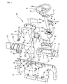
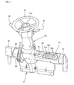
- a modular cowl assembly for forklift trucks includes a cowl body 10 which provides a base for supporting a variety of driver interface devices in front of a driver's compartment of, e.g., forklift trucks.
- the cowl body 10 is removably mounted on a truck body (not shown) and composed of a material with high strength such as a press-formed metal plate and an injection-molded synthetic resin.
- a console 20 is attached to the center area of the cowl body 10.
- the console 20 serves to partially enclose or hold a steering column 22, a direction indicator lever 26 and a forward-reverse lever 28.
- Attached to the top end of the steering column 22 is a steering wheel 24 that has a buzzer button 24a at its center.
- the steering column 22 is tiltably attached to a support bracket 12 of the cowl body 10 and can be tilted forwards or rearwards by the action of a tilting cylinder 22b into an angular position selected by a driver.
- the console 20 is provided with a console cover 30 enclosing the most part of the steering column 22.
- the console cover 30 consists of a top cover 32 which is divided into first and second split cover parts 32a, 32b and a bottom cover 34 which is also divided into first and second split cover parts 34a, 34b.
- the second split cover part 32b of the top cover 32 is attached to the steering column 22 by means of a support bracket 22c and then secured to the first split cover parts 32a by virtue of a screw 32c, thus joining the top cover 32 and the steering column 22 together.
- the first and second split cover parts 34a, 34b of the bottom cover 34 are joined together by means of a screw 34c and the bottom cover 34 thus joined is secured to the cowl body 20.
- the modular cowl assembly of the present invention includes a right cowl cover 40 disposed at the right side of the console 20 and affixed to the cowl body 10 by a fastener means.
- the fastener means comprises a plurality of first fixing lugs 42 integrally formed with the right cowl cover 40, a plurality of second fixing lugs 44 integrally formed with the cowl body 10 in alignment with the first fixing lugs 42, and fixing screws 46 for combining the first fixing lugs 42 and the second fixing lugs 44 together.
- the right cowl cover 40 is provided with an inwardly recessed storage pocket 47 and an elongated opening 48 formed through the thickness of the right cowl cover 40.
- the storage pocket 47 serves to store small articles such as cups, coins, clips and the like for ready use.
- the elongated opening 48 is adapted for receiving an instrument board 50 that includes, for example, a cooling water temperature indicator 50a, a transmission oil temperature indicator 50b, a fuel indicator 50c, an engine preheat indicator (not shown) and the like.
- the instrument board 50 is electrically associated with a controller (not shown) mounted on a truck body.
- the modular cowl assembly of the present invention includes a left cowl cover 60 disposed at the left side of the console 20 and affixed to the cowl body 10 by a fastener means.
- the fastener means comprises a plurality of first fixing lugs 62 integrally formed with the left cowl cover 60, a plurality of second fixing lugs 64 integrally formed with the cowl body 10 in alignment with the first fixing lugs 62, and fixing screws 66 for combining the first fixing lugs 62 and the second fixing lugs 64 together.
- the left cowl cover 60 is provided with a slot 68 formed through the thickness thereof for swingably receiving a parking brake lever 69.
- the parking brake lever 69 can be pulled by the driver when he or she wishes to place the forklift truck in a parking condition.
- the parking brake lever 69 is operatively connected to a brake (not shown) with a cable so that, when pulled, it can cause the brake to arrest a driving axle against rotation.
- the modular cowl assembly of the present invention includes a right end cover 70 disposed at an outer end side of the right cowl cover 40 for closing an open end of the right cowl cover 40 and a left end cover 80 disposed at an outer end side of the left cowl cover 60 for closing an open end of the left cowl cover 60.
- the right end cover 70 is attached to the right cowl cover 40 by means of a fastener means.
- the fastener means comprises a plurality of fixing ears 72 integrally formed with the right end cover 70, a plurality of fixing bosses 74 integrally formed with the right cowl cover 40 in alignment with the fixing ears 72, and fixing screws 76 for combining the fixing ears 72 and the fixing bosses 74 together.
- the right end cover 70 of such configuration is so positioned at the outer end side of the right cowl cover 40 as to close the open end of the right cowl cover 40. This prevents foreign matters from infiltrating into the interior space of the right cowl cover 40
- the left end cover 80 is attached to the left cowl cover 60 by means of a fastener means.
- the fastener means comprises a plurality of fixing ears 82 integrally formed with the left end cover 80, a plurality of fixing bosses 84 integrally formed with the left cowl cover 60 in alignment with the fixing ears 82, and fixing screws 86 for combining the fixing ears 82 and the fixing bosses 84 together.
- the left end cover 80 of such configuration is so positioned at the outer end side of the left cowl cover 60 as to close the open end of the right cowl cover 60. This prevents foreign matters from infiltrating into the interior space of the left cowl cover 60.
- Each of the right end cover 70 and the left end cover 80 is designed to have a length that varies with the kinds of forklift trucks to which is applied the modular cowl assembly.
- the right end cover 70 and the left end cover 80 are produced in multiple numbers in correspondence to the kinds of forklift trucks.
- the right end cover 70 and the left end cover 80 may be length-adjustably produced by use of, e.g., a bellows or other extendible components.
- the modular cowl assembly of the present invention incorporates a cowl body 10 and a variety of driver interface devices, such as a steering column 22, a steering wheel 24, a direction indicator lever 26, a forward-reverse lever 28, a parking brake lever 69 and an instrument board 50, in a single module.
- driver interface devices such as a steering column 22, a steering wheel 24, a direction indicator lever 26, a forward-reverse lever 28, a parking brake lever 69 and an instrument board 50, in a single module.
- the modular cowl assembly thus produced is transported, handled and attached to the truck body as a unit in the process of manufacture and assembly of the forklift trucks.
Landscapes
- Engineering & Computer Science (AREA)
- Transportation (AREA)
- Mechanical Engineering (AREA)
- Structural Engineering (AREA)
- Chemical & Material Sciences (AREA)
- Combustion & Propulsion (AREA)
- Civil Engineering (AREA)
- Life Sciences & Earth Sciences (AREA)
- Geology (AREA)
- Forklifts And Lifting Vehicles (AREA)
- Body Structure For Vehicles (AREA)
Claims (6)
- Modulare Verkleidungsanordnung für Gabelstapler, die umfasst:einen Verkleidungskörper (10), der an einem Fahrzeugkörper vor einer Fahrerkabine zu montieren ist;eine Bedienungskonsole (20), die wenigstens teilweise eine Lenksäule (22), einen Richtungsanzeigerhebel (26) und einen Vorwärtsfahrt/Rückwärtsfahrt-Hebel (28) umschließt und hält;eine Tragstütze (12), um die Bedienungskonsole (20) an dem Verkleidungskörper (10) zu unterstützen;eine rechte Verkleidungsabdeckung (40), die an einer rechten Seite der Bedienungskonsole (20) angeordnet ist, um wenigstens einen Teil des Verkleidungskörpers (10) abzudecken;eine linke Verkleidungsabdeckung (60), die an einer linken Seite der Bedienungskonsole (20) angeordnet ist, um wenigstens einen Teil des Verkleidungskörpers (10) abzudecken;ein Verkleidungsabdeckungs-Befestigungsmittel, um die rechte Verkleidungsabdeckung (40) und die linke Verkleidungsabdeckung (60) am Verkleidungskörper (10) zu befestigen;eine rechte Stirnabdeckung (70), die an einer äußeren Stirnseite der rechten Verkleidungsabdeckung (40) angeordnet ist, um ein offenes Ende der rechten Verkleidungsabdeckung (40) zu verschließen; undeine linke Stirnabdeckung (80), die an einer äußeren Stirnseite der linken Verkleidungsabdeckung (60) angeordnet ist, um ein offenes Ende der linken Verkleidungsabdeckung (60) zu verschließen;gekennzeichnet durchein Stirnabdeckungs-Befestigungsmittel, um die rechte Stirnabdeckung (70) und die linke Stirnabdeckung (80) an der rechten Verkleidungsabdeckung (40) bzw. an der linken Verkleidungsabdeckung (60) zu befestigen,wobei sowohl die rechte Stirnabdeckung (70) als auch die linke Stirnabdeckung (80) eine Länge besitzt, die unter Berücksichtigung der des Typs des Gabelstaplers, an dem die modulare Verkleidungsanordnung angebracht wird, ausgewählt ist.
- Modulare Verkleidungsanordnung nach Anspruch 1, die ferner ein Armaturenbrett (50) umfasst, das an der rechten Verkleidungsabdeckung (40) befestigt ist.
- Modulare Verkleidungsanordnung nach Anspruch 1, die ferner einen Parkbremshebel (69) umfasst, der an der linken Verkleidungsabdeckung (60) schwenkbar befestigt ist.
- Modulare Verkleidungsanordnung nach Anspruch 2, die ferner einen Parkbremshebel (69) umfasst, der an der linken Verkleidungsabdeckung (60) schwenkbar befestigt ist.
- Modulare Verkleidungsanordnung nach Anspruch 1, wobei sowohl das Verkleidungsabdeckungs-Befestigungsmittel als auch das Stirnabdeckungs-Befestigungsmittel eine Schraube umfasst.
- Modulare Verkleidungsanordnung nach Anspruch 1, wobei die Lenksäule (22) an einer Tragstütze (12) des Verkleidungskörpers (10) neigbar befestigt ist und durch die Betätigung eines Neigungszylinders (22b) in eine durch einen Fahrer ausgewählte angewinkelte Position geneigt werden kann.
Applications Claiming Priority (1)
| Application Number | Priority Date | Filing Date | Title |
|---|---|---|---|
| KR1020040114276A KR100605011B1 (ko) | 2004-12-28 | 2004-12-28 | 지게차용 제어모듈 |
Publications (2)
| Publication Number | Publication Date |
|---|---|
| EP1676771A1 EP1676771A1 (de) | 2006-07-05 |
| EP1676771B1 true EP1676771B1 (de) | 2009-05-06 |
Family
ID=35741457
Family Applications (1)
| Application Number | Title | Priority Date | Filing Date |
|---|---|---|---|
| EP05028176A Expired - Lifetime EP1676771B1 (de) | 2004-12-28 | 2005-12-22 | Modulare Haubenmontagestrasse |
Country Status (5)
| Country | Link |
|---|---|
| US (1) | US20060138804A1 (de) |
| EP (1) | EP1676771B1 (de) |
| KR (1) | KR100605011B1 (de) |
| CN (1) | CN100577492C (de) |
| DE (1) | DE602005014327D1 (de) |
Families Citing this family (3)
| Publication number | Priority date | Publication date | Assignee | Title |
|---|---|---|---|---|
| CN101570211B (zh) * | 2008-05-04 | 2011-04-06 | 孙乙钦 | 一种汽车转向柱用可调装饰罩 |
| DE102009043182A1 (de) * | 2009-09-26 | 2011-03-31 | Jungheinrich Ag | Flurförderzeug mit einem Fahrzeugrahmen und mindestens einem Verkleidungsteil |
| US8590931B2 (en) * | 2011-10-28 | 2013-11-26 | Nissan North America, Inc. | Steering column cover skirt attachment |
Family Cites Families (24)
| Publication number | Priority date | Publication date | Assignee | Title |
|---|---|---|---|---|
| US4026349A (en) * | 1976-03-15 | 1977-05-31 | Schaap Robert E | Cowl for an industrial electric truck |
| US4126202A (en) | 1977-07-20 | 1978-11-21 | Massey-Ferguson, Inc. | Vehicle control box module |
| US5036942A (en) * | 1990-08-14 | 1991-08-06 | Ford New Holland, Inc. | Rotatable operator control unlocking mechanism |
| JP2580926B2 (ja) | 1991-12-27 | 1997-02-12 | 株式会社豊田自動織機製作所 | 産業車両のインストルメントパネル |
| JP3432018B2 (ja) * | 1994-10-21 | 2003-07-28 | 本田技研工業株式会社 | 自動車車体の支持構造 |
| DE19513089C2 (de) * | 1995-04-07 | 2000-04-20 | Man Nutzfahrzeuge Ag | Fahrerhaus eines Frontlenker-Lastkraftwagens |
| JPH0960703A (ja) * | 1995-08-29 | 1997-03-04 | Aisin Seiki Co Ltd | 駆動装置 |
| FR2747358B1 (fr) * | 1996-04-11 | 1998-06-05 | Reydel Sa | Tableau de bord pour vehicule tel que notamment vehicule automobile |
| US5959421A (en) * | 1997-12-31 | 1999-09-28 | Daewoo Heavy Industries Ltd. | Motor direction control device for electromotive vehicles |
| US6328520B1 (en) * | 1998-08-10 | 2001-12-11 | Thomas B. Maclay | Vehicle mounted large bale loading, transporting and unloading system |
| DE19854940B4 (de) * | 1998-11-27 | 2006-09-07 | Behr Gmbh & Co. Kg | Baugruppe für ein Cockpit eines Kraftfahrzeuges |
| JP3716151B2 (ja) * | 2000-02-10 | 2005-11-16 | 三菱重工業株式会社 | フォークリフト車両のフレーム構造 |
| US6371551B1 (en) * | 2000-10-24 | 2002-04-16 | Ford Global Technologies, Inc. | Integrated steering column, instrument panel, and cowl body structure |
| US6524054B2 (en) * | 2001-05-15 | 2003-02-25 | Finus Maney | Vehicular mounted lift |
| CA2355516C (en) * | 2001-08-17 | 2009-05-05 | Louis A. Nagy | Cross car support structure |
| JP2003327396A (ja) | 2002-05-13 | 2003-11-19 | Komatsu Forklift Co Ltd | 産業車両用ダッシュボードカバーモジュール |
| US7174804B2 (en) * | 2002-12-03 | 2007-02-13 | Associated Spring Raymond | Positioning mechanism for tilt steering |
| US6871721B2 (en) * | 2003-06-03 | 2005-03-29 | The Raymond Corporation | Ergonomic operator compartment for operators of differing heights |
| US8974169B2 (en) * | 2004-03-15 | 2015-03-10 | Richard J. Mizner | Fork lift attachment tools and methods |
| US9090441B2 (en) * | 2004-03-15 | 2015-07-28 | Richard J. Mizner | Truck fork attachment including adjustable mast for ground clearance |
| US20060076427A1 (en) * | 2004-10-12 | 2006-04-13 | Schneider Joseph L Jr | Lift truck with heating system |
| US20070092366A1 (en) * | 2005-10-24 | 2007-04-26 | Bose Joseph M | Forklift Attachment Utilizing Plow Mounts and Frame |
| US20070166138A1 (en) * | 2006-01-18 | 2007-07-19 | Brooks Brady B | Truck Mounted Multifunction Lifting System and Method |
| US20070213869A1 (en) * | 2006-02-08 | 2007-09-13 | Intermec Ip Corp. | Cargo transporter with automatic data collection devices |
-
2004
- 2004-12-28 KR KR1020040114276A patent/KR100605011B1/ko not_active Expired - Lifetime
-
2005
- 2005-12-22 EP EP05028176A patent/EP1676771B1/de not_active Expired - Lifetime
- 2005-12-22 DE DE602005014327T patent/DE602005014327D1/de not_active Expired - Lifetime
- 2005-12-23 US US11/337,051 patent/US20060138804A1/en not_active Abandoned
- 2005-12-28 CN CN200510135729A patent/CN100577492C/zh not_active Expired - Lifetime
Also Published As
| Publication number | Publication date |
|---|---|
| KR20060075479A (ko) | 2006-07-04 |
| DE602005014327D1 (de) | 2009-06-18 |
| US20060138804A1 (en) | 2006-06-29 |
| KR100605011B1 (ko) | 2006-07-28 |
| CN100577492C (zh) | 2010-01-06 |
| CN1796265A (zh) | 2006-07-05 |
| EP1676771A1 (de) | 2006-07-05 |
Similar Documents
| Publication | Publication Date | Title |
|---|---|---|
| US6499550B2 (en) | Working vehicle having detachable panel cover | |
| US12606104B2 (en) | Vehicle console assembly | |
| US11827307B2 (en) | Operating device for human-powered vehicle | |
| US11981391B2 (en) | Operating device for human-powered vehicle | |
| US6428197B1 (en) | Spotlight for an all-terrain vehicle | |
| EP1676771B1 (de) | Modulare Haubenmontagestrasse | |
| US7506715B2 (en) | Safety device for a motor vehicle including a front-end structure | |
| US20220355633A1 (en) | Rear arrangement for a vehicle | |
| US20030032327A1 (en) | Filler unit for a control device of a vehicle | |
| EP0348273B1 (de) | Aufbau eines pneumatischen Bremskraftverstärkers | |
| JP2004306889A (ja) | 車両用リヤゲート | |
| US20040194571A1 (en) | Turn signal mounting assembly | |
| EP2048071B1 (de) | Grätschsitz-Fahrzeug | |
| CA2494964C (en) | Adapter for mounting items on a steering column | |
| JP2005067498A (ja) | 作業車両。 | |
| JPH07277253A (ja) | 小型車両の荷掛けフックの取り付け構造 | |
| JP2003226496A (ja) | フォークリフトにおけるトップカバーの取付構造 | |
| TW202415578A (zh) | 用於人力交通工具之操作裝置 | |
| JP2598565Y2 (ja) | 車両のステアリング装置 | |
| JPH0367912B2 (de) | ||
| JP2000281291A (ja) | カウンタバランス型フォークリフト | |
| JP2025127828A (ja) | 作業車 | |
| JP2002172942A (ja) | トラクタの燃料タンク取り付け構造 | |
| JP2003040148A (ja) | 作業車両の操縦席構造 | |
| EP2047351B1 (de) | Lasthandhabungsfahrzeug |
Legal Events
| Date | Code | Title | Description |
|---|---|---|---|
| PUAI | Public reference made under article 153(3) epc to a published international application that has entered the european phase |
Free format text: ORIGINAL CODE: 0009012 |
|
| 17P | Request for examination filed |
Effective date: 20051222 |
|
| AK | Designated contracting states |
Kind code of ref document: A1 Designated state(s): AT BE BG CH CY CZ DE DK EE ES FI FR GB GR HU IE IS IT LI LT LU LV MC NL PL PT RO SE SI SK TR |
|
| AX | Request for extension of the european patent |
Extension state: AL BA HR MK YU |
|
| 17Q | First examination report despatched |
Effective date: 20070126 |
|
| AKX | Designation fees paid |
Designated state(s): DE FR GB IT |
|
| RIC1 | Information provided on ipc code assigned before grant |
Ipc: B66F 9/075 20060101ALN20080913BHEP Ipc: B62D 25/14 20060101AFI20080913BHEP |
|
| GRAP | Despatch of communication of intention to grant a patent |
Free format text: ORIGINAL CODE: EPIDOSNIGR1 |
|
| GRAP | Despatch of communication of intention to grant a patent |
Free format text: ORIGINAL CODE: EPIDOSNIGR1 |
|
| GRAS | Grant fee paid |
Free format text: ORIGINAL CODE: EPIDOSNIGR3 |
|
| GRAA | (expected) grant |
Free format text: ORIGINAL CODE: 0009210 |
|
| AK | Designated contracting states |
Kind code of ref document: B1 Designated state(s): DE FR GB IT |
|
| REG | Reference to a national code |
Ref country code: GB Ref legal event code: FG4D |
|
| REF | Corresponds to: |
Ref document number: 602005014327 Country of ref document: DE Date of ref document: 20090618 Kind code of ref document: P |
|
| PLBE | No opposition filed within time limit |
Free format text: ORIGINAL CODE: 0009261 |
|
| STAA | Information on the status of an ep patent application or granted ep patent |
Free format text: STATUS: NO OPPOSITION FILED WITHIN TIME LIMIT |
|
| 26N | No opposition filed |
Effective date: 20100209 |
|
| REG | Reference to a national code |
Ref country code: GB Ref legal event code: 732E Free format text: REGISTERED BETWEEN 20110804 AND 20110810 |
|
| REG | Reference to a national code |
Ref country code: FR Ref legal event code: TP Owner name: DOOSAN INDUSTRIAL VEHICLE CO., LTD, KR Effective date: 20111013 |
|
| REG | Reference to a national code |
Ref country code: DE Ref legal event code: R082 Ref document number: 602005014327 Country of ref document: DE Representative=s name: SPARING - ROEHL - HENSELER, DE Effective date: 20111117 Ref country code: DE Ref legal event code: R081 Ref document number: 602005014327 Country of ref document: DE Owner name: DOOSAN CORPORATION, KR Free format text: FORMER OWNER: DOOSAN INFRACORE CO., LTD., INCHEON, KR Effective date: 20111117 |
|
| REG | Reference to a national code |
Ref country code: DE Ref legal event code: R082 Ref document number: 602005014327 Country of ref document: DE Representative=s name: SPARING - ROEHL - HENSELER, DE |
|
| REG | Reference to a national code |
Ref country code: GB Ref legal event code: 732E Free format text: REGISTERED BETWEEN 20140220 AND 20140226 |
|
| REG | Reference to a national code |
Ref country code: DE Ref legal event code: R082 Ref document number: 602005014327 Country of ref document: DE Representative=s name: SPARING - ROEHL - HENSELER, DE Effective date: 20140212 Ref country code: DE Ref legal event code: R081 Ref document number: 602005014327 Country of ref document: DE Owner name: DOOSAN CORPORATION, KR Free format text: FORMER OWNER: DOOSAN INDUSTRIAL VEHICLE CO., LTD., INCHEON, KR Effective date: 20140212 |
|
| REG | Reference to a national code |
Ref country code: FR Ref legal event code: CA Effective date: 20140320 Ref country code: FR Ref legal event code: CD Owner name: DOOSAN CORPORATION, KR Effective date: 20140320 |
|
| REG | Reference to a national code |
Ref country code: FR Ref legal event code: PLFP Year of fee payment: 11 |
|
| REG | Reference to a national code |
Ref country code: FR Ref legal event code: PLFP Year of fee payment: 12 |
|
| REG | Reference to a national code |
Ref country code: FR Ref legal event code: PLFP Year of fee payment: 13 |
|
| REG | Reference to a national code |
Ref country code: DE Ref legal event code: R081 Ref document number: 602005014327 Country of ref document: DE Owner name: DOOSAN INDUSTRIAL VEHICLE CO., LTD., KR Free format text: FORMER OWNER: DOOSAN CORPORATION, SEOUL, KR Ref country code: DE Ref legal event code: R081 Ref document number: 602005014327 Country of ref document: DE Owner name: DOOSAN BOBCAT KOREA CO., LTD., KR Free format text: FORMER OWNER: DOOSAN CORPORATION, SEOUL, KR |
|
| REG | Reference to a national code |
Ref country code: DE Ref legal event code: R081 Ref document number: 602005014327 Country of ref document: DE Owner name: DOOSAN BOBCAT KOREA CO., LTD., KR Free format text: FORMER OWNER: DOOSAN INDUSTRIAL VEHICLE CO., LTD., INCHEON, KR |
|
| PGFP | Annual fee paid to national office [announced via postgrant information from national office to epo] |
Ref country code: DE Payment date: 20241029 Year of fee payment: 20 |
|
| PGFP | Annual fee paid to national office [announced via postgrant information from national office to epo] |
Ref country code: GB Payment date: 20241031 Year of fee payment: 20 |
|
| PGFP | Annual fee paid to national office [announced via postgrant information from national office to epo] |
Ref country code: FR Payment date: 20241111 Year of fee payment: 20 |
|
| PGFP | Annual fee paid to national office [announced via postgrant information from national office to epo] |
Ref country code: IT Payment date: 20241112 Year of fee payment: 20 |
|
| REG | Reference to a national code |
Ref country code: DE Ref legal event code: R071 Ref document number: 602005014327 Country of ref document: DE |
|
| REG | Reference to a national code |
Ref country code: GB Ref legal event code: PE20 Expiry date: 20251221 |