EP1675971B1 - Method for coating a substrate surface using a plasma beam - Google Patents
Method for coating a substrate surface using a plasma beam Download PDFInfo
- Publication number
- EP1675971B1 EP1675971B1 EP04786991A EP04786991A EP1675971B1 EP 1675971 B1 EP1675971 B1 EP 1675971B1 EP 04786991 A EP04786991 A EP 04786991A EP 04786991 A EP04786991 A EP 04786991A EP 1675971 B1 EP1675971 B1 EP 1675971B1
- Authority
- EP
- European Patent Office
- Prior art keywords
- plasma
- powder
- fine granular
- nozzle
- substrate surface
- Prior art date
- Legal status (The legal status is an assumption and is not a legal conclusion. Google has not performed a legal analysis and makes no representation as to the accuracy of the status listed.)
- Revoked
Links
Images
Classifications
-
- C—CHEMISTRY; METALLURGY
- C23—COATING METALLIC MATERIAL; COATING MATERIAL WITH METALLIC MATERIAL; CHEMICAL SURFACE TREATMENT; DIFFUSION TREATMENT OF METALLIC MATERIAL; COATING BY VACUUM EVAPORATION, BY SPUTTERING, BY ION IMPLANTATION OR BY CHEMICAL VAPOUR DEPOSITION, IN GENERAL; INHIBITING CORROSION OF METALLIC MATERIAL OR INCRUSTATION IN GENERAL
- C23C—COATING METALLIC MATERIAL; COATING MATERIAL WITH METALLIC MATERIAL; SURFACE TREATMENT OF METALLIC MATERIAL BY DIFFUSION INTO THE SURFACE, BY CHEMICAL CONVERSION OR SUBSTITUTION; COATING BY VACUUM EVAPORATION, BY SPUTTERING, BY ION IMPLANTATION OR BY CHEMICAL VAPOUR DEPOSITION, IN GENERAL
- C23C4/00—Coating by spraying the coating material in the molten state, e.g. by flame, plasma or electric discharge
- C23C4/12—Coating by spraying the coating material in the molten state, e.g. by flame, plasma or electric discharge characterised by the method of spraying
- C23C4/134—Plasma spraying
Definitions
- the invention relates to a method for coating a substrate surface using a plasma jet according to the preamble of claim 1 and to an application of the method according to claim 12.
- refractory layers to a substrate surface by means of a plasma jet
- suitable substances e.g. Tungsten or oxide ceramics are supplied in powder form in a plasma free jet.
- thermal plasmas in which temperatures of up to 20,000 ° C. prevail in the core of the exiting free plasma jet.
- the plasma stabilization takes place here by high currents (> 200 A) and easy to ionizing gases.
- Such a plasma causes a high temperature load of the component to be coated. If the coating process takes place under atmosphere, metallic coating materials also partly oxidize. Therefore, the range of use is very narrow.
- the coating and / or processing of low-melting materials is possible, if at all, only by extremely complex process control and the use of strong cooling.
- WO 01/32949 describes a method for coating surfaces, in which a precursor material is reacted by means of a plasma and the reaction product is then deposited on the surface to be coated.
- This precursor material be it liquid and / or solid, is fed separately from the working gas into the plasma jet. As soon as a reaction of the introduced material is to take place, sufficient heating of the recurser material must be achieved.
- the present invention has for its object to provide a method of the type mentioned, by means of which well adhering layers can be applied to metal, glass, plastic or other substrate surfaces.
- the powder applied to the substrate surface by the free plasma jet is applied with good adhesion without the substrate temperature rising inadmissibly. Nevertheless, an excellent adhesion of the applied layer is achieved even under air atmosphere by this microscopic plasma process.
- Metallic layers are also characterized by their extremely low oxygen content.
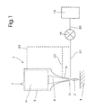
- Fig.1 shows a known per se plasma nozzle 1 for generating a free plasma jet 2, which emerges from a lower nozzle opening 3 of the Plasmatrons 1 and is directed to a substrate surface 4.
- the plasmatron 1 usually has an elongated, tubular housing 5, which tapers conically in the lower region 6 to the already mentioned nozzle opening 3.
- the metal housing 5 is grounded and forms with the nozzle tip, for example, an outer electrode.
- a primary imbalance plasma with low electrical power ( ⁇ 5 kW) is indicated within the plasmatron 5 - with box 11 - by high frequency alternating current (> 10 kHz), for example via a magnetron, an RF plasma, a direct high voltage discharge, a Coronabarriereentladung or similar generated.
- a plasma or working gas is introduced from above through a supply line 7 so fluidly that thereby stabilizes the primary plasma (gas-stabilized plasmatron and, for example, vortex-stabilized plasmatron).
- plasma or working gas preferably air or steam is used (cost).
- the air can still be added as needed.
- Nitrogen, carbon dioxide, methane or noble gases are added.
- these other gases can also be used in pure form or in mixtures.
- vapors of other liquids in pure form or in mixtures are to be used as plasma gases.
- the emerging atmospheric plasma jet 2 is characterized in particular by a low temperature (in the core region ⁇ 500 ° C.) and low geometric expansion (diameter typically ⁇ 5 mm).
- the free plasma jet 2 is then added as a fluidized, fine-grained powder in exactly metered amount, which is intended to form the intended coating on the substrate surface. There it is due to the interaction with the plasma up or even melted and accelerated in the direction of the surface to be coated, where it ultimately settles.
- the powder material is delivered from a container 15 by means of a powder conveyor 16 and optionally introduced into the secondary plasma or primary plasma.
- the low-temperature plasma is characterized in that after formation of an electrically or electromagnetically generated primary imbalance plasma (non-thermal plasma) in a partially closed plasma generator, the directed by suitable measures primary plasma jet by means of an annular nozzle at the transition to the environment (outlet 3) strong is accelerated and consequently after the nozzle forms a secondary plasma at ambient pressure. If the substrate surface is electrically conductive, a further voltage (so-called transferred arc or also direct plasmatron) can also be applied between the nozzle and the substrate.
- the temperature of the plasma measured with a thermocouple type NiCr / Ni, tip diameter 4 mm, at 10 mm distance from the nozzle outlet is less than 900 ° C in the core of the secondary plasma jet (2) at ambient pressure.
- a powder conveyor 16 is preferably one of the PCT patent application no. PCT / EP02 / 10709 known device for supplying metered quantities of fine-grained bulk material used, which has at least two alternately fillable and emptying metering chambers, wherein the metering chambers each by connection to a suction or. Vacuum line filled with the powder and emptied by connection to a compressed gas line while the powder is fluidized by the pressurized gas and pneumatically conveyed on.
- Such a device as a powder conveyor 16 allows a highly precise metering and both a pulsed and a continuous, agglomeration-free supply of the finest powder whose grain size in the nanometer range to micrometer range (1 nm to 100 microns).
- the possible embodiments of such a powder conveyor for electronically controllable promotion can be found in the aforementioned patent application and are therefore not described here in detail in detail.
- the fluidized, fine-grained powder is introduced via a line 20 into the plasmatron 1 and there into the secondary plasma and / or introduced via a line 21 directly into the emerging from the nozzle opening 3 plasma jet 2.
- a further possibility is to supply the powder via a likewise indicated by dashed lines 23 directly through the primary plasma in the flow direction of the plasma jet to the nozzle opening 3.
- the amount of compressed gas required for the pneumatic delivery of the powder material is preferably 2 to 20% of the plasma gas amount.
- the plasma gas consumption is about 100 to 5000 nl / h).
- the powder applied to the substrate surface 4 by the plasma jet 2 is applied with good adhesion without the substrate temperature rising inadmissibly.
- the temperature of the plasma measured with a thermocouple type NiCr / Ni, tip diameter 3 mm, at a distance of 10 mm from the nozzle outlet is less than 900 ° C in the core of the secondary plasma free jet at ambient pressure.
- the substrate temperature increase during and after the coating process is well below 100 ° C., preferably below 50 ° C. Nevertheless, excellent adhesion of the coated layer is achieved by this microscopic atmospheric plasma process.
- An advantage of the method according to the invention is that the substrate surface 4 to be coated requires no special preparation.
- a surface cleaning can be carried out by the plasma process itself.
- initially one or more times the plasma jet is directed without powder additive on the surface to be coated before the actual coating takes place.
- This process is used primarily for tempering the surface and for its micro- or nanostructuring.
- the inventive method is excellent for example for applying a zinc layer on welding or soldering of galvanized metal parts or sheets, which are used in particular in the auto industry. It is known that the zinc layer of the conventionally galvanized metal parts or sheets is removed during welding or soldering, whereby there is a risk of corrosion at such locations.
- a plasma jet having a precisely defined width can be directed onto the site to be treated, for example a weld, and a zinc layer having a corresponding width (eg 2 to 3 ⁇ m / s) can be directed through a relative feed substrate / plasma nozzle (eg 0.3 m / s) 8 mm) can be applied exactly.
- the powder feed is in the range of about 0.5 to 10 g / min.
- the achievable layer thicknesses are typically 0.1 to 100 microns per overflow.
- the device can be applied directly after the welding process (in-line process).
- the method can also be used for medical purposes and serve, for example, for applying biologically active layers to skin substitutes or bone implants, with the aim of faster and improved integration of the implant into the human tissue.
- the method can also be used for the metered or selective pretreating or metallization of plastics, paper, semiconductors or nonconductors, for example for the production of electrically conductive layers of Zn, Cu or Ag on Si wafers.
- the method can be used for the decomposition-free application of well-adhering layers of plastics, such as polyamide, or high-performance plastics, such as PEEK with or without addition of inorganic nanometer to some micrometer-sized particles on plastics, wood, paper or metals.
- plastics such as polyamide
- high-performance plastics such as PEEK
- powders with a specifically chemically and / or physically modified surface result. These powders can then serve as an improved or new precursor for other processes (eg, changing the hydrophobic behavior of soot into a hydrophilic behavior).
Abstract
Description
Die Erfindung betrifft ein Verfahren zur Beschichtung einer Substratoberfläche unter Verwendung eines Plasmastrahles gemäss dem Oberbegriff des Anspruches 1 sowie eine Anwendung des Verfahrens nach Anspruch 12.The invention relates to a method for coating a substrate surface using a plasma jet according to the preamble of
Es ist bekannt, mittels eines Plasmastrahles hochschmelzende Schichten auf eine Substratoberfläche aufzutragen, indem geeignete Stoffe wie z.B. Wolfram oder Oxidkeramik in Pulverform in einen Plasmafreistrahl zugeführt werden. Es handelt sich dabei um sogenannte thermische Plasmen, bei denen im Kern des austretenden freien Plasmastrahles Temperaturen bis zu 20'000°C herrschen. Die Plasmastabilisierung findet hierbei durch hohe Stromstärken (> 200 A) und einfach zu ionisierende Gase statt. Ein derartiges Plasma bedingt eine hohe Temperaturbelastung des zu beschichtenden Bauteiles. Findet der Beschichtungsvorgang unter Atmosphäre statt, oxidieren ausserdem metallische Beschichtungswerkstoffe teilweise. Daher ist der Verwendungsbereich sehr eingeengt. Die Beschichtung und oder Verarbeitung niedrigschmelzender Werkstoffe ist, wenn überhaupt, nur durch eine äusserst aufwendige Prozessführung und dem Einsatz starker Kühlung möglich.It is known to apply refractory layers to a substrate surface by means of a plasma jet, by using suitable substances, e.g. Tungsten or oxide ceramics are supplied in powder form in a plasma free jet. These are so-called thermal plasmas in which temperatures of up to 20,000 ° C. prevail in the core of the exiting free plasma jet. The plasma stabilization takes place here by high currents (> 200 A) and easy to ionizing gases. Such a plasma causes a high temperature load of the component to be coated. If the coating process takes place under atmosphere, metallic coating materials also partly oxidize. Therefore, the range of use is very narrow. The coating and / or processing of low-melting materials is possible, if at all, only by extremely complex process control and the use of strong cooling.
In der Druckschrift
Es ist ausserdem erwähnt, dass mit einer solchen Vorrichtung Stoffe dosiert unter oder ohne Druck in einen Beschichtungsprozess, z.B. Plasma-Pulver-Auftragsschweissen, und anderen zugeführt werden können, was als allgemeiner Hinweis zu verstehen ist.It is also mentioned that with such a device, substances are metered under or without pressure into a coating process, e.g. Plasma powder deposition welding, and others can be fed, which is to be understood as a general guide.
In der Druckschrift
Der vorliegenden Erfindung liegt die Aufgabe zugrunde, ein Verfahren der eingangs genannten Art vorzuschlagen, mittels welchen gut haftende Schichten auf Metall, Glas, Kunststoff oder andere Substratoberflächen aufgetragen werden können.The present invention has for its object to provide a method of the type mentioned, by means of which well adhering layers can be applied to metal, glass, plastic or other substrate surfaces.
Diese Aufgabe wird erfindungsgemäss durch ein Verfahren mit den Merkmalen des Anspruches 1 gelöst.This object is achieved according to the invention by a method having the features of
Bevorzugte Weitergestaltungcn des erfindungsgemässen Verfahrens bilden den Gegenstand der abhängigen Ansprüche.Preferred developments of the process according to the invention form the subject matter of the dependent claims.
Besonders vorteilhaft ist die Anwendung des erfindungsgemässen Verfahrens zum Aufbringen einer Zinkschicht auf Schweiss-oder Lötstellen von verzinkten Metallteilen oder Blechen, idealerweise direkt nach dem Schweiss- bzw. Lötvorgang in dem das Plasmatron hinter dem Schweissverfahren nachgeführt wird und die Prozesswärme des vorherigen Fügevorganges ausnutzt, um eine verbesserte Anbindung der Zinkschicht an das Bauteil zu erreichen.Particularly advantageous is the application of the inventive method for applying a zinc layer on welding or soldering of galvanized metal parts or sheets, ideally directly after the welding or soldering process in which the Plasmatron is tracked behind the welding process and the process heat of the previous joining process exploits to achieve an improved connection of the zinc layer to the component.
Das vom freien Plasmastrahl auf die Substratoberfläche aufgebrachte Pulver wird auf diese gut haftend aufgetragen, ohne dass die Substrattemperatur unzulässig ansteigt. Dennoch wird durch diesen mikroskopischen Plasmaprozess auch unter Luftatmosphäre eine ausgezeichnete Haftung der aufgetragenen Schicht erreicht. Metallische Schichten zeichnen sich ferner durch Ihren äusserst geringen Sauerstoffgehalt aus.The powder applied to the substrate surface by the free plasma jet is applied with good adhesion without the substrate temperature rising inadmissibly. Nevertheless, an excellent adhesion of the applied layer is achieved even under air atmosphere by this microscopic plasma process. Metallic layers are also characterized by their extremely low oxygen content.
Die Erfindung wird nachfolgend anhand der Zeichnung näher erläutert. Es zeigt:
- Fig. 1
- schematisch ein Prinzip des erfindungsgemässen Verfahrens.
- Fig. 1
- schematically a principle of the inventive method.
Das Plasmatron 1 weist üblicherweise ein langgestrecktes, rohrförmiges Gehäuse 5 auf, das sich im unteren Bereich 6 zu der bereits erwähnten Düsenöffnung 3 konisch verjüngt. Das metallene Gehäuse 5 ist geerdet und bildet mit der Düsenspitze zum Beispiel eine Aussenelektrode. Ein primäres Ungleichgewichts-Plasma mit niedriger elektrischer Leistung (< 5 kW) wird innerhalb des Plasmatrons 5 - mit Box 11 angedeutet - durch hochfrequenten Wechselstrom (> 10 KHz) beispielsweise über ein Magnetron, ein RF-Plasma, eine direkte Hochspannungsentladung, einer Coronabarriereentladung oder ähnlichem erzeugt. In das Plasmatron 1 wird von oben durch eine Zuleitung 7 ein Plasma- bzw. Arbeitsgas so strömungstechnisch eingeleitet, dass dadurch das primäre Plasma stabilisiert wird (gasstabilisiertes Plasmatron und bspw. auch vortexstabilsiertes Plasmatron).The
Als Plasma- bzw. Arbeitsgas wird vorzugsweise Luft oder auch Wasserdampf eingesetzt (kostengünstig). Der Luft können bei Bedarf noch z.B. Stickstoff, Kohlendioxid, Methan oder Edelgase beigemischt werden. Diese anderen Gase können jedoch auch in reiner Form oder in Mischungen verwendet werden. Auch sind Dämpfe anderer Flüssigkeiten in reiner Form oder in Mischungen als Plasmagase zu verwenden.As plasma or working gas preferably air or steam is used (cost). The air can still be added as needed. Nitrogen, carbon dioxide, methane or noble gases are added. However, these other gases can also be used in pure form or in mixtures. Also, vapors of other liquids in pure form or in mixtures are to be used as plasma gases.
Der austretende atmosphärische Plasmafreistrahl 2 zeichnet sich insbesondere durch eine niedrige Temperatur (im Kernbereich < 500 °C) und geringer geometrischer Ausdehnung aus (Durchmesser typischerweise < 5 mm). Erfindungsgemäss wird nun dem freien Plasmastrahl 2 als ein fluidisiertes, feinkörniges Pulver dasjenige Material in genau dosierter Menge zugefügt, das die vorgesehene Beschichtung der Substratoberfläche bilden soll. Dort wird es infolge der Wechselwirkung mit dem Plasma auf- oder auch nur angeschmolzen und in Richtung der zu beschichtenden Oberfläche beschleunigt, wo es sich letztlich niederschlägt. Das Pulvermaterial wird dabei aus einem Behälter 15 mittels eines Pulverförderers 16 geliefert und wahlweise in das sekundäre Plasma oder auch primäre Plasma eingeleitet.The emerging
Das Niedertemperaturplasma zeichnet sich dadurch aus, dass das nach Ausbildung eines elektrisch oder elektromagnetisch erzeugten primären Ungleichgewichts-Plasmas (Nichtthermisches Plasma) in einem partiell geschlossen Plasmaerzeuger, der durch geeignete Massnahmen gerichtete primäre Plasmastrahl mittels einer ringförmigen Düse am Übergang zur Umgebung (Austrittsöffnung 3) stark beschleunigt wird und sich folgedessen nach der Düse ein sekundäres Plasma bei Umgebungsdruck ausbildet. Ist die Substratoberfläche elektrisch leitend, kann zudem eine weitere Spannung (sogenannter übertragener Lichbogen oder auch direktes Plasmatron) zwischen Düse und dem Substrat angelegt werden. Die Temperatur des Plasmas gemessen mit einem Thermoelement Typ NiCr/Ni, Spitzendurchmesser 4 mm, in 10 mm Abstand vom Düsenaustritt beträgt weniger als 900°C im Kern des sekundären Plasmastrahles (2) bei Umgebungsdruck.The low-temperature plasma is characterized in that after formation of an electrically or electromagnetically generated primary imbalance plasma (non-thermal plasma) in a partially closed plasma generator, the directed by suitable measures primary plasma jet by means of an annular nozzle at the transition to the environment (outlet 3) strong is accelerated and consequently after the nozzle forms a secondary plasma at ambient pressure. If the substrate surface is electrically conductive, a further voltage (so-called transferred arc or also direct plasmatron) can also be applied between the nozzle and the substrate. The temperature of the plasma measured with a thermocouple type NiCr / Ni,
Als Pulverförderer 16 wird vorzugsweise eine aus der PCT-Patentanmeldung Nr.
Das Einschalten und Ausschalten des Sauganschlusses sowie das Einschalten und Ausschalten des Druckgasanschlusses erfolgt über pneumatisch und/oder hydraulisch gesteuerte Ventile. Eine solche Vorrichtung als Pulverförderer 16 erlaubt eine höchst präzise Dosierung und sowohl eine gepulste als auch eine kontinuierliche, agglomerationsfreie Zuführung des feinsten Pulvers, dessen Korngrösse im Nanometerbereich bis Mikrometerbereich (1 nm bis 100 µm) liegt. Die möglichen Ausgestaltungen eines derartigen Pulverförderers zur elektronisch steuerbaren Förderung sind der vorstehend genannten Patentanmeldung zu entnehmen und werden daher hier im Detail nicht näher beschrieben.The switching on and off of the suction connection as well as the switching on and off of the compressed gas connection takes place via pneumatically and / or hydraulically controlled valves. Such a device as a
Das fluidisierte, feinkörnige Pulver wird über eine Leitung 20 in das Plasmatron 1 und dort in das sekundäre Plasma eingeführt und/oder über eine Leitung 21 direkt in den aus der Düsenöffnung 3 austretenden Plasmastrahl 2 eingeleitet. Von Vorteil ist auch eine Pulverzuführung in den sich zur Düsenöffnung 3 hin verjüngenden Bereich 6 des Plasmatrons 1 (oder in die Düsenöffnung 3 selber) über eine in
Die Menge des für die pneumatische Förderung des Pulvermaterials benötigten Druckgases beträgt vorzugsweise 2 bis 20% der Plasmagasmenge. Der Plasmagasverbrauch liegt etwa bei 100 bis 5000 nl/h).The amount of compressed gas required for the pneumatic delivery of the powder material is preferably 2 to 20% of the plasma gas amount. The plasma gas consumption is about 100 to 5000 nl / h).
Das vom Plasmafreistrahl 2 auf die Substratoberfläche 4 aufgebrachte Pulver wird auf diese gut haftend aufgetragen, ohne dass die Substrattemperatur unzulässig ansteigt. Die Temperatur des Plasmas gemessen mit einem Thermoelement Typ NiCr/Ni, Spitzendurchmesser 3 mm, in 10 mm Abstand vom Düsenaustritt beträgt weniger als 900°C im Kern des sekundären Plasmafreistrahles bei Umgebungsdruck. Die Substrattemperaturerhöhung liegt während und nach dem Beschichtungsprozess deutlich unterhalb 100°C, vorzugsweise unter 50°C. Dennoch wird durch diesen mikroskopischen atmosphärischen Plasmaprozess eine ausgezeichnete Haftung der aufgetragenen Schicht erreicht.The powder applied to the
Ein Vorteil des erfindungsgemässen Verfahrens besteht darin, dass die zu beschichtende Substratoberfläche 4 keiner speziellen Vorbereitung bedarf.An advantage of the method according to the invention is that the
Eine Oberflächenreinigung kann durch den Plasmaprozess selber durchgeführt werden. Mit Vorteil wird zu diesem Zweck anfänglich ein- oder mehrmals der Plasmastrahl ohne Pulverzusatz auf die zu beschichtende Fläche gerichtet, bevor die eigentliche Beschichtung erfolgt. Dieser Vorgang dient vor allem zur Temperierung der Oberfläche und zu deren Mikro- bzw. Nanostrukturierung.A surface cleaning can be carried out by the plasma process itself. Advantageously, for this purpose initially one or more times the plasma jet is directed without powder additive on the surface to be coated before the actual coating takes place. This process is used primarily for tempering the surface and for its micro- or nanostructuring.
Das erfindungsgemässe Verfahren eignet sich ausgezeichnet beispielsweise zum Aufbringen einer Zinkschicht auf Schweiss- oder Lötstellen von verzinkten Metallteilen oder Blechen, die insbesondere in der Autoindustrie verwendet werden. Bekanntlich wird die Zinkschicht der konventionell verzinkten Metallteile oder Bleche beim Schweissen oder Löten entfernt, wodurch eine Korrosionsgefahr an solchen Stellen besteht. Mit dem erfindungsgemässen Verfahren kann ein Plasmastrahl mit genau definierter Breite auf die zu behandelnde Stelle, beispielsweise eine Schweissnaht, gerichtet werden und durch einen relativen Vorschub Substrat/Plasmadüse (z.B. 0,3 m/s) eine Zinkschicht mit einer entsprechenden Breite (z.B. 2 bis 8 mm) exakt aufgetragen werden. Als das feinkörnige, dem Plasmastrahl zugefügte Pulvermaterial wird kommerziell erhältlicher Zinkstaub verwendet. Die Pulverzufuhr liegt im Bereich von ca. 0,5 bis 10 g/min. Die erzielbaren Schichtdicken betragen typischerweise 0,1 bis 100 Mikrometer pro Überlauf. Die Vorrichtung kann direkt dem Schweissprozess nachlaufend angewendet werden (In-Line Prozess).The inventive method is excellent for example for applying a zinc layer on welding or soldering of galvanized metal parts or sheets, which are used in particular in the auto industry. It is known that the zinc layer of the conventionally galvanized metal parts or sheets is removed during welding or soldering, whereby there is a risk of corrosion at such locations. With the method according to the invention, a plasma jet having a precisely defined width can be directed onto the site to be treated, for example a weld, and a zinc layer having a corresponding width (
Selbstverständlich können auch andere Materialien (Metalle, Keramiken, Thermoplaste oder auch deren Mischungen etc.) auf andere Substratflächen (Metall, Glas, Kunststoff etc.) mit dem erfindungsgemässen Verfahren aufgetragen werden und Funktionsschichten wie beispielsweise Schutz-, Verschleiss-, Isolierschichten oder auch Schichten mit antibakteriellen, selbstreinigenden oder auch katalytischen Eigenschaften bilden. Das Verfahren kann aber auch zu medizinischen Zwecken genutzt werden und beispielsweise zum Aufbringen von biologisch aktiven Schichten auf Hautersatz oder Knochenimplantaten dienen, mit Ziel einer schnelleren und verbesserten Integration des Implantates in das menschliche Gewebe.Of course, other materials (metals, ceramics, thermoplastics or mixtures thereof, etc.) can be applied to other substrate surfaces (metal, glass, plastic, etc.) with the inventive method and functional layers such as protective, wear, insulating layers or layers with antibacterial, form self-cleaning or catalytic properties. However, the method can also be used for medical purposes and serve, for example, for applying biologically active layers to skin substitutes or bone implants, with the aim of faster and improved integration of the implant into the human tissue.
Das Verfahren kann auch zum dosierten bzw. schonenden und gezielten Vormetallisieren oder Metallisieren von Kunststoffen, Papier, Halbleitern oder Nichtleitern, beispielsweise zur Herstellung elektrisch leitfähiger Schichten aus Zn, Cu oder Ag auf Si-Wafern, angewendet werden.The method can also be used for the metered or selective pretreating or metallization of plastics, paper, semiconductors or nonconductors, for example for the production of electrically conductive layers of Zn, Cu or Ag on Si wafers.
Des Weiteren kann das Verfahren angewendet werden zur zersetzungsfreien Aufbringung von gut haftenden Schichten aus Kunststoffen, wie Polyamid, oder Hochleistungs-Kunststoffen, wie PEEK ohne oder mit Zusätzen von anorganischen nanometer- bis einige mikrometergrosse Partikel auf Kunststoffe, Holz, Papier oder Metalle.Furthermore, the method can be used for the decomposition-free application of well-adhering layers of plastics, such as polyamide, or high-performance plastics, such as PEEK with or without addition of inorganic nanometer to some micrometer-sized particles on plastics, wood, paper or metals.
Wird das in den Plasmastrahl eingegebene Pulver oder Pulvergemisch nachfolgend nicht auf eine Oberfläche als Schicht aufgetragen, sondern über eine geeignete Vorrichtung gefangen, ergeben sich Pulver mit gezielt chemisch und oder physikalisch veränderter Oberfläche. Diese Pulver können dann als verbessertes oder neues Vorprodukt für andere Prozesse dienen (bspw. Änderung des hydrophoben Verhaltens von Russ in ein hydrophiles Verhalten).If the powder or powder mixture introduced into the plasma jet is subsequently not applied to a surface as a layer but trapped by a suitable device, powders with a specifically chemically and / or physically modified surface result. These powders can then serve as an improved or new precursor for other processes (eg, changing the hydrophobic behavior of soot into a hydrophilic behavior).
Claims (17)
- Method for coating a substrate surface (4) using a plasma beam (2), to which a fine granular powder forming the coating is added in metered amount by a controllable device as powder feed (16), characterised in that
a beam (8, 2) of a low-temperature plasma is directed at the substrate surface (4), to which this powder is added in metered amount, whereby the substrate temperature increase during and after the coating process lies below 100°C, preferably under 50°C. - Method according to claim 1, characterised in that the particle size of the fine granular powder or of the powder mixture can be in the nanometre range between 1 nanometre to 10 micrometres.
- Method according to claim 1 or 2, characterised in that the fine granular powder is supplied from a container (15) by means of a powder feeder (16) which has at least two dosing chambers which alternately can be filled and emptied, whereby the dosing chambers are each filled with the powder by connection to a suction or vacuum line, and emptied by connection to a pressure gas line and thereby the powder is fluidized by the pressure gas and conveyed onwards pneumatically, whereby the suction and the pressure gas connections are opened and closed via pneumatically and/or hydraulically controlled valves.
- Method according to anyone of the claims 1 to 3, characterised in that the plasma is created in a plasma nozzle (1) under the introduction of a working gas and/or of a vaporable fluid and generation of a discharge which is initiated by high voltage and/or high-frequency electrical and/or electromagnetic coupling and the primary plasma beam (8) is blown out through an opening (3) of the plasmatron (1) in the form of a nozzle onto the substrate surface (4), whereby the fine granular powder is introduced into the primary plasma, and from there goes into the secondary plasma beam (2) and/or is introduced directly into the secondary plasma beam (2) emerging from the nozzle opening (3).
- Method according to claim 4, characterised in that the fine granular powder is introduced into an area (6) of the plasma nozzle (1) tapering towards the nozzle opening (3).
- Method according to claim 4, characterised in that the fine granular powder is fed directly (23) into the primary plasma.
- Method according to one of the claims 3 to 6, characterised in that the volume of pressure gas for pneumatic feeding (20) of the fine granular powder amounts to 2 to 20% of the plasma gas volume (7).
- Method according to one of claims 4 to 7, characterised in that air is used as working and/or plasma gas.
- Method according to one of the claims 1 to 8, characterised in that in the low-temperature plasma, after forming an electrically or electromagnetically generated primary non-equilibrium plasma in a partially-closed plasma generator, the primary plasma beam, directed by suitable means, is powerfully accelerated by means of an annular nozzle (3) at the transition to the environment and consequently a secondary plasma forms after the nozzle at ambient pressure.
- Method according to one of the claims 1 to 8, characterised in that the substrate surface (4) is cleansed and/or micro- or nanostructured by the secondary plasma beam (2) without the addition of powder.
- Method according to one of the claims 4 to 10, characterised in that a high-frequency alternating or direct current at frequencies of between 10 kHz to 10 GHz and an electrical power of less than 5 kW is used to generate the primary plasma (8).
- Method according to claim 1 or 2, characterised in that the fine granular powder is converted into an aqueous suspension and added to the plasma with the aid of at least one feeder unit.
- Application of the method according to one of claims 1 to 12 to deposit a zinc coating on welding or solder points of galvanised metal parts or sheets.
- Application of the method according to one of the claims 1 to 12 for the deposition of solder, with and without flux, onto components.
- Application of the method according to one of the claims 1 to 12 for the deposition copper coatings.
- Application of the method according to one of the claims 1 to 12 for metered pre-metallisation or metallisation of plastics, paper, semiconductors or dielectrics, like for the manufacture of electrically-conductive coatings made from Zn, Cu or Ag on Si wafers.
- Application of the method according to one of the claims 1 to 12 for non-decomposing deposition of coatings made from plastics, such as polyamide, or high-performance plastics, such as PEEK with or without additives of anorganic particles with a size in the nanometre to a few micrometres range, made from plastics, wood, paper or metals.
Priority Applications (1)
| Application Number | Priority Date | Filing Date | Title |
|---|---|---|---|
| PL04786991T PL1675971T3 (en) | 2003-09-26 | 2004-09-23 | Method for coating a substrate surface using a plasma beam |
Applications Claiming Priority (2)
| Application Number | Priority Date | Filing Date | Title |
|---|---|---|---|
| CH01639/03A CH696811A5 (en) | 2003-09-26 | 2003-09-26 | Process for coating a substrate surface using a plasma jet. |
| PCT/EP2004/010675 WO2005031026A1 (en) | 2003-09-26 | 2004-09-23 | Method for coating a substrate surface using a plasma beam |
Publications (2)
| Publication Number | Publication Date |
|---|---|
| EP1675971A1 EP1675971A1 (en) | 2006-07-05 |
| EP1675971B1 true EP1675971B1 (en) | 2010-05-19 |
Family
ID=34383946
Family Applications (1)
| Application Number | Title | Priority Date | Filing Date |
|---|---|---|---|
| EP04786991A Revoked EP1675971B1 (en) | 2003-09-26 | 2004-09-23 | Method for coating a substrate surface using a plasma beam |
Country Status (8)
| Country | Link |
|---|---|
| EP (1) | EP1675971B1 (en) |
| JP (1) | JP2007521395A (en) |
| AT (1) | ATE468418T1 (en) |
| CH (1) | CH696811A5 (en) |
| DE (1) | DE502004011185D1 (en) |
| ES (1) | ES2345986T3 (en) |
| PL (1) | PL1675971T3 (en) |
| WO (1) | WO2005031026A1 (en) |
Cited By (10)
| Publication number | Priority date | Publication date | Assignee | Title |
|---|---|---|---|---|
| WO2012065704A1 (en) | 2010-11-15 | 2012-05-24 | Michael Dvorak | Process for producing coating components of finely particulate powders |
| WO2012123530A1 (en) | 2011-03-16 | 2012-09-20 | Reinhausen Plasma Gmbh | Coating, and method and device for coating |
| DE102011052121A1 (en) | 2011-07-25 | 2013-01-31 | Eckart Gmbh | Coating process using special powder coating materials and use of such coating materials |
| WO2013014213A2 (en) | 2011-07-25 | 2013-01-31 | Eckart Gmbh | Methods for substrate coating and use of additive-containing powdered coating materials in such methods |
| DE102011052118A1 (en) | 2011-07-25 | 2013-01-31 | Eckart Gmbh | Method for applying a coating to a substrate, coating and use of particles |
| WO2013014211A2 (en) | 2011-07-25 | 2013-01-31 | Eckart Gmbh | Use of specially coated powdered coating materials and coating methods using such coating materials |
| DE102011052119A1 (en) | 2011-07-25 | 2013-01-31 | Eckart Gmbh | Coating method of particle-containing powdery coating material used for automobile component, involves performing flame spraying, high-speed flame spraying, thermal plasma spraying and/or non-thermal plasma spraying method |
| DE202012011217U1 (en) | 2012-11-21 | 2014-02-27 | Leoni Bordnetz-Systeme Gmbh | Device for dividing a stream of material in a surface coating system and such a coating system |
| WO2015055486A1 (en) | 2013-10-14 | 2015-04-23 | Plasma Innovations GmbH | Production method for a plasma-coated molded body and component |
| EP2959992A1 (en) | 2014-06-26 | 2015-12-30 | Eckart GmbH | Method for producing a particulate-containing aerosol |
Families Citing this family (19)
| Publication number | Priority date | Publication date | Assignee | Title |
|---|---|---|---|---|
| EP1871921B1 (en) * | 2005-03-22 | 2021-04-28 | Erbslöh Aluminium GmbH | Method for partial or complete coating of the surfaces of an aluminium material component |
| DE102006061435A1 (en) * | 2006-12-23 | 2008-06-26 | Leoni Ag | Method and device for spraying in particular a conductor track, electrical component with a conductor track and metering device |
| EP2179071B1 (en) * | 2007-08-14 | 2016-04-13 | Université Libre de Bruxelles | Method of depositing nanoparticles on a support |
| EP2419231B1 (en) * | 2009-04-17 | 2021-05-05 | Michael Dvorak | Method for powder coating or for producing composite materials, preferably when processing plastics or spray compacting metals |
| WO2010118896A2 (en) * | 2009-04-17 | 2010-10-21 | Bayer International Sa | Method and system of feeding a carbon nano tubes (cnts) to a fluid for forming a composite material |
| FR2947814B1 (en) * | 2009-07-13 | 2011-10-14 | Serigne Dioum | FLUID DEPOLLUTION PRODUCT AND METHOD OF OBTAINING |
| DE102010014552A1 (en) | 2010-03-22 | 2011-09-22 | Timo Brummer | Coating a substrate surface using a plasma beam or plasma beams, comprises directing a beam of an atmospheric low-temperature plasma to the substrate surface according to respective plasma coating nozzle in opposition to thermal injection |
| DE102010032187A1 (en) * | 2010-07-23 | 2012-01-26 | Reinhausen Plasma Gmbh | Process for producing a solar cell and solar cell |
| DE202010016599U1 (en) * | 2010-12-15 | 2012-03-16 | Leoni Bordnetz-Systeme Gmbh | Apparatus for spraying a structure of conductive material onto a substrate |
| DE102010056325B3 (en) * | 2010-12-27 | 2012-02-16 | Maschinenfabrik Reinhausen Gmbh | Method for producing a shield |
| DE202012011219U1 (en) | 2012-11-21 | 2014-02-24 | Leoni Bordnetz-Systeme Gmbh | Device for dissolving agglomerations of solid particles in a stream, in particular gas stream in a surface coating plant |
| CN103074569A (en) * | 2013-01-29 | 2013-05-01 | 电子科技大学 | Atmosphere glow discharge low-temperature plasma coating device |
| DE102013103693A1 (en) * | 2013-04-12 | 2014-10-16 | Reinhausen Plasma Gmbh | Method and device for constructing a structure on a substrate |
| DE102013010126B4 (en) * | 2013-06-18 | 2015-12-31 | Häuser & Co. GmbH | Plasmapulverspritzverfahren and apparatus for coating panels for boiler walls in conjunction with a laser beam device |
| DE202013007063U1 (en) | 2013-08-07 | 2013-09-03 | Marco De Paolis | Electrode for use in plasma spray nozzles |
| DE102014219756A1 (en) * | 2014-09-30 | 2016-03-31 | Evonik Degussa Gmbh | Plasma coating of thermoelectric active material with nickel and tin |
| ES2704132T3 (en) | 2016-01-21 | 2019-03-14 | Evonik Degussa Gmbh | Rational procedure for the powder metallurgical production of thermoelectric components |
| EP3327165A1 (en) * | 2016-11-24 | 2018-05-30 | Valeo Iluminacion | Method for creating a conductive track |
| DE102020212302A1 (en) | 2020-09-29 | 2022-03-31 | Contitech Techno-Chemie Gmbh | Plastic pipe with integrated connection |
Family Cites Families (10)
| Publication number | Priority date | Publication date | Assignee | Title |
|---|---|---|---|---|
| JPS6452053A (en) * | 1987-08-19 | 1989-02-28 | Oki Electric Ind Co Ltd | Production of superconducting ceramic body |
| JP2772971B2 (en) * | 1989-04-18 | 1998-07-09 | 松下電器産業株式会社 | Welding method for surface treated steel sheet |
| JPH09143667A (en) * | 1995-11-21 | 1997-06-03 | Mitsubishi Heavy Ind Ltd | Production of high temperature member made of rhenium |
| JP2995250B2 (en) * | 1997-07-22 | 1999-12-27 | 哲二 平野 | A method for plasma spraying titanium oxide powder on a substrate and a product having a plasma sprayed coating. |
| DE19807086A1 (en) * | 1998-02-20 | 1999-08-26 | Fraunhofer Ges Forschung | Atmospheric pressure plasma deposition for adhesion promoting, corrosion protective, surface energy modification or mechanical, electrical or optical layers |
| DE19856307C1 (en) * | 1998-12-07 | 2000-01-13 | Bosch Gmbh Robert | Apparatus for producing a free cold plasma jet |
| DE29919142U1 (en) * | 1999-10-30 | 2001-03-08 | Agrodyn Hochspannungstechnik G | Plasma nozzle |
| JP2002121024A (en) * | 2000-10-12 | 2002-04-23 | Seiko Epson Corp | Method for manufacturing titanium oxide film, titanium oxide film and solar cell |
| JP4216453B2 (en) * | 2000-11-15 | 2009-01-28 | 株式会社東芝 | Manufacturing method of coating member |
| EP1432964B1 (en) * | 2001-09-29 | 2012-05-23 | Michael Dvorak | Method and device for conveying dosed quantities of a fine-grained bulk material |
-
2003
- 2003-09-26 CH CH01639/03A patent/CH696811A5/en not_active IP Right Cessation
-
2004
- 2004-09-23 EP EP04786991A patent/EP1675971B1/en not_active Revoked
- 2004-09-23 WO PCT/EP2004/010675 patent/WO2005031026A1/en active Application Filing
- 2004-09-23 PL PL04786991T patent/PL1675971T3/en unknown
- 2004-09-23 DE DE502004011185T patent/DE502004011185D1/en active Active
- 2004-09-23 AT AT04786991T patent/ATE468418T1/en active
- 2004-09-23 JP JP2006527345A patent/JP2007521395A/en active Pending
- 2004-09-23 ES ES04786991T patent/ES2345986T3/en active Active
Cited By (15)
| Publication number | Priority date | Publication date | Assignee | Title |
|---|---|---|---|---|
| WO2012065704A1 (en) | 2010-11-15 | 2012-05-24 | Michael Dvorak | Process for producing coating components of finely particulate powders |
| WO2012123530A1 (en) | 2011-03-16 | 2012-09-20 | Reinhausen Plasma Gmbh | Coating, and method and device for coating |
| WO2013014211A2 (en) | 2011-07-25 | 2013-01-31 | Eckart Gmbh | Use of specially coated powdered coating materials and coating methods using such coating materials |
| WO2013014214A2 (en) | 2011-07-25 | 2013-01-31 | Eckart Gmbh | Coating method using special powdered coating materials and use of such coating materials |
| WO2013014213A2 (en) | 2011-07-25 | 2013-01-31 | Eckart Gmbh | Methods for substrate coating and use of additive-containing powdered coating materials in such methods |
| DE102011052118A1 (en) | 2011-07-25 | 2013-01-31 | Eckart Gmbh | Method for applying a coating to a substrate, coating and use of particles |
| DE102011052121A1 (en) | 2011-07-25 | 2013-01-31 | Eckart Gmbh | Coating process using special powder coating materials and use of such coating materials |
| DE102011052120A1 (en) | 2011-07-25 | 2013-01-31 | Eckart Gmbh | Use of specially coated, powdery coating materials and coating methods using such coating materials |
| WO2013014212A2 (en) | 2011-07-25 | 2013-01-31 | Eckart Gmbh | Method for applying a coating to a substrate, coating, and use of particles |
| DE102011052119A1 (en) | 2011-07-25 | 2013-01-31 | Eckart Gmbh | Coating method of particle-containing powdery coating material used for automobile component, involves performing flame spraying, high-speed flame spraying, thermal plasma spraying and/or non-thermal plasma spraying method |
| US9580787B2 (en) | 2011-07-25 | 2017-02-28 | Eckart Gmbh | Coating method using special powdered coating materials and use of such coating materials |
| DE202012011217U1 (en) | 2012-11-21 | 2014-02-27 | Leoni Bordnetz-Systeme Gmbh | Device for dividing a stream of material in a surface coating system and such a coating system |
| WO2015055486A1 (en) | 2013-10-14 | 2015-04-23 | Plasma Innovations GmbH | Production method for a plasma-coated molded body and component |
| DE102013111306A1 (en) | 2013-10-14 | 2015-04-30 | Ensinger Gmbh | Manufacturing method for a plasma-coated molded body and component |
| EP2959992A1 (en) | 2014-06-26 | 2015-12-30 | Eckart GmbH | Method for producing a particulate-containing aerosol |
Also Published As
| Publication number | Publication date |
|---|---|
| JP2007521395A (en) | 2007-08-02 |
| CH696811A5 (en) | 2007-12-14 |
| ATE468418T1 (en) | 2010-06-15 |
| ES2345986T3 (en) | 2010-10-07 |
| PL1675971T3 (en) | 2010-10-29 |
| WO2005031026A1 (en) | 2005-04-07 |
| DE502004011185D1 (en) | 2010-07-01 |
| EP1675971A1 (en) | 2006-07-05 |
Similar Documents
| Publication | Publication Date | Title |
|---|---|---|
| EP1675971B1 (en) | Method for coating a substrate surface using a plasma beam | |
| EP2486163B1 (en) | Atmospheric pressure plasma method for producing surface-modified particles and coatings | |
| DE10261303B3 (en) | Electrically conducting composite material used in automotive applications as electrical contact components, such as connectors or connections, comprises a metal strip and a contact layer containing carbon powder and a further additive | |
| EP2104750B1 (en) | Method and device for spraying a conductive line | |
| EP3083107B1 (en) | Device and method for melting a material without a crucible and for atomizing the melted material in order to produce powder | |
| EP1230414A1 (en) | Method and device for plasma coating surfaces | |
| DE102011052118A1 (en) | Method for applying a coating to a substrate, coating and use of particles | |
| WO2012123530A1 (en) | Coating, and method and device for coating | |
| DE10223865B4 (en) | Process for the plasma coating of workpieces | |
| EP1095169A1 (en) | Method and device for producing a powder aerosol and use thereof | |
| AT517694B1 (en) | Apparatus and method for applying a coating | |
| DE102012107076A1 (en) | Method and device for thermal spraying of coating materials | |
| EP3768870B1 (en) | Apparatus for conveying and charging powder, apparatus for producing a layered structure on a surface region of a component, sheet-like heating element and method for producing a sheet-like heating element | |
| DE102010014552A1 (en) | Coating a substrate surface using a plasma beam or plasma beams, comprises directing a beam of an atmospheric low-temperature plasma to the substrate surface according to respective plasma coating nozzle in opposition to thermal injection | |
| EP2468914B1 (en) | Method and device for arc spraying | |
| EP1358943B1 (en) | Method and apparatus for electric arc spraying | |
| DE102018113643A1 (en) | Device for coating a surface | |
| DE10331664B4 (en) | Plasma spraying process and device suitable for this purpose | |
| DE10256257A1 (en) | Device and method for coating a substrate and coating on a substrate | |
| WO2015055711A1 (en) | Method and device for producing particles in an atmospheric pressure plasma | |
| EP4082670A1 (en) | Device for thermal coating by means of wire arc spraying | |
| DE102010033290A1 (en) | Applying coating made of conductive coating material on surface of component to be coated, comprises melting wire made of coating material and transporting melt by gas stream to surface, and carrying out the melting by an induction coil | |
| DE10314015A1 (en) | Process for coating substrates with a plastic containing an injection material in the form of plastic encased with metal and/or ceramic comprises feeding the injection material into a colder injection region during thermal injection |
Legal Events
| Date | Code | Title | Description |
|---|---|---|---|
| PUAI | Public reference made under article 153(3) epc to a published international application that has entered the european phase |
Free format text: ORIGINAL CODE: 0009012 |
|
| 17P | Request for examination filed |
Effective date: 20060315 |
|
| AK | Designated contracting states |
Kind code of ref document: A1 Designated state(s): AT BE BG CH CY CZ DE DK EE ES FI FR GB GR HU IE IT LI LU MC NL PL PT RO SE SI SK TR |
|
| 17Q | First examination report despatched |
Effective date: 20060829 |
|
| DAX | Request for extension of the european patent (deleted) | ||
| GRAP | Despatch of communication of intention to grant a patent |
Free format text: ORIGINAL CODE: EPIDOSNIGR1 |
|
| GRAJ | Information related to disapproval of communication of intention to grant by the applicant or resumption of examination proceedings by the epo deleted |
Free format text: ORIGINAL CODE: EPIDOSDIGR1 |
|
| GRAP | Despatch of communication of intention to grant a patent |
Free format text: ORIGINAL CODE: EPIDOSNIGR1 |
|
| GRAS | Grant fee paid |
Free format text: ORIGINAL CODE: EPIDOSNIGR3 |
|
| GRAA | (expected) grant |
Free format text: ORIGINAL CODE: 0009210 |
|
| STAA | Information on the status of an ep patent application or granted ep patent |
Free format text: STATUS: THE PATENT HAS BEEN GRANTED |
|
| AK | Designated contracting states |
Kind code of ref document: B1 Designated state(s): AT BE BG CH CY CZ DE DK EE ES FI FR GB GR HU IE IT LI LU MC NL PL PT RO SE SI SK TR |
|
| REG | Reference to a national code |
Ref country code: GB Ref legal event code: FG4D Free format text: NOT ENGLISH |
|
| REG | Reference to a national code |
Ref country code: CH Ref legal event code: EP |
|
| REG | Reference to a national code |
Ref country code: IE Ref legal event code: FG4D Free format text: LANGUAGE OF EP DOCUMENT: GERMAN |
|
| REF | Corresponds to: |
Ref document number: 502004011185 Country of ref document: DE Date of ref document: 20100701 Kind code of ref document: P |
|
| REG | Reference to a national code |
Ref country code: NL Ref legal event code: T3 |
|
| REG | Reference to a national code |
Ref country code: SE Ref legal event code: TRGR |
|
| REG | Reference to a national code |
Ref country code: ES Ref legal event code: FG2A Ref document number: 2345986 Country of ref document: ES Kind code of ref document: T3 |
|
| REG | Reference to a national code |
Ref country code: PL Ref legal event code: T3 |
|
| PG25 | Lapsed in a contracting state [announced via postgrant information from national office to epo] |
Ref country code: SI Free format text: LAPSE BECAUSE OF FAILURE TO SUBMIT A TRANSLATION OF THE DESCRIPTION OR TO PAY THE FEE WITHIN THE PRESCRIBED TIME-LIMIT Effective date: 20100519 |
|
| PG25 | Lapsed in a contracting state [announced via postgrant information from national office to epo] |
Ref country code: CY Free format text: LAPSE BECAUSE OF FAILURE TO SUBMIT A TRANSLATION OF THE DESCRIPTION OR TO PAY THE FEE WITHIN THE PRESCRIBED TIME-LIMIT Effective date: 20100519 Ref country code: GR Free format text: LAPSE BECAUSE OF FAILURE TO SUBMIT A TRANSLATION OF THE DESCRIPTION OR TO PAY THE FEE WITHIN THE PRESCRIBED TIME-LIMIT Effective date: 20100820 |
|
| REG | Reference to a national code |
Ref country code: IE Ref legal event code: FD4D |
|
| PG25 | Lapsed in a contracting state [announced via postgrant information from national office to epo] |
Ref country code: PT Free format text: LAPSE BECAUSE OF FAILURE TO SUBMIT A TRANSLATION OF THE DESCRIPTION OR TO PAY THE FEE WITHIN THE PRESCRIBED TIME-LIMIT Effective date: 20100920 Ref country code: IE Free format text: LAPSE BECAUSE OF FAILURE TO SUBMIT A TRANSLATION OF THE DESCRIPTION OR TO PAY THE FEE WITHIN THE PRESCRIBED TIME-LIMIT Effective date: 20100519 Ref country code: DK Free format text: LAPSE BECAUSE OF FAILURE TO SUBMIT A TRANSLATION OF THE DESCRIPTION OR TO PAY THE FEE WITHIN THE PRESCRIBED TIME-LIMIT Effective date: 20100519 Ref country code: EE Free format text: LAPSE BECAUSE OF FAILURE TO SUBMIT A TRANSLATION OF THE DESCRIPTION OR TO PAY THE FEE WITHIN THE PRESCRIBED TIME-LIMIT Effective date: 20100519 |
|
| PLBI | Opposition filed |
Free format text: ORIGINAL CODE: 0009260 |
|
| PG25 | Lapsed in a contracting state [announced via postgrant information from national office to epo] |
Ref country code: SK Free format text: LAPSE BECAUSE OF FAILURE TO SUBMIT A TRANSLATION OF THE DESCRIPTION OR TO PAY THE FEE WITHIN THE PRESCRIBED TIME-LIMIT Effective date: 20100519 Ref country code: RO Free format text: LAPSE BECAUSE OF FAILURE TO SUBMIT A TRANSLATION OF THE DESCRIPTION OR TO PAY THE FEE WITHIN THE PRESCRIBED TIME-LIMIT Effective date: 20100519 |
|
| PLAX | Notice of opposition and request to file observation + time limit sent |
Free format text: ORIGINAL CODE: EPIDOSNOBS2 |
|
| 26 | Opposition filed |
Opponent name: LEONI BORDNETZ-SYSTEME GMBH Effective date: 20110218 Opponent name: ECKART GMBH Effective date: 20110218 |
|
| PG25 | Lapsed in a contracting state [announced via postgrant information from national office to epo] |
Ref country code: MC Free format text: LAPSE BECAUSE OF NON-PAYMENT OF DUE FEES Effective date: 20100930 |
|
| REG | Reference to a national code |
Ref country code: DE Ref legal event code: R026 Ref document number: 502004011185 Country of ref document: DE Effective date: 20110218 |
|
| PLAF | Information modified related to communication of a notice of opposition and request to file observations + time limit |
Free format text: ORIGINAL CODE: EPIDOSCOBS2 |
|
| PLBB | Reply of patent proprietor to notice(s) of opposition received |
Free format text: ORIGINAL CODE: EPIDOSNOBS3 |
|
| PGFP | Annual fee paid to national office [announced via postgrant information from national office to epo] |
Ref country code: CZ Payment date: 20110922 Year of fee payment: 8 |
|
| PG25 | Lapsed in a contracting state [announced via postgrant information from national office to epo] |
Ref country code: LU Free format text: LAPSE BECAUSE OF NON-PAYMENT OF DUE FEES Effective date: 20100923 Ref country code: HU Free format text: LAPSE BECAUSE OF FAILURE TO SUBMIT A TRANSLATION OF THE DESCRIPTION OR TO PAY THE FEE WITHIN THE PRESCRIBED TIME-LIMIT Effective date: 20101120 Ref country code: BG Free format text: LAPSE BECAUSE OF FAILURE TO SUBMIT A TRANSLATION OF THE DESCRIPTION OR TO PAY THE FEE WITHIN THE PRESCRIBED TIME-LIMIT Effective date: 20100519 |
|
| PGFP | Annual fee paid to national office [announced via postgrant information from national office to epo] |
Ref country code: FI Payment date: 20120921 Year of fee payment: 9 Ref country code: SE Payment date: 20120919 Year of fee payment: 9 |
|
| PGFP | Annual fee paid to national office [announced via postgrant information from national office to epo] |
Ref country code: PL Payment date: 20120918 Year of fee payment: 9 |
|
| PGFP | Annual fee paid to national office [announced via postgrant information from national office to epo] |
Ref country code: ES Payment date: 20120926 Year of fee payment: 9 |
|
| PGFP | Annual fee paid to national office [announced via postgrant information from national office to epo] |
Ref country code: NL Payment date: 20120920 Year of fee payment: 9 Ref country code: BE Payment date: 20120920 Year of fee payment: 9 |
|
| PGFP | Annual fee paid to national office [announced via postgrant information from national office to epo] |
Ref country code: CH Payment date: 20121228 Year of fee payment: 9 |
|
| PG25 | Lapsed in a contracting state [announced via postgrant information from national office to epo] |
Ref country code: BG Free format text: LAPSE BECAUSE OF FAILURE TO SUBMIT A TRANSLATION OF THE DESCRIPTION OR TO PAY THE FEE WITHIN THE PRESCRIBED TIME-LIMIT Effective date: 20100819 |
|
| RDAF | Communication despatched that patent is revoked |
Free format text: ORIGINAL CODE: EPIDOSNREV1 |
|
| BERE | Be: lapsed |
Owner name: DVORAK, MICHAEL Effective date: 20130930 |
|
| REG | Reference to a national code |
Ref country code: NL Ref legal event code: V1 Effective date: 20140401 |
|
| REG | Reference to a national code |
Ref country code: SE Ref legal event code: EUG |
|
| PG25 | Lapsed in a contracting state [announced via postgrant information from national office to epo] |
Ref country code: CZ Free format text: LAPSE BECAUSE OF NON-PAYMENT OF DUE FEES Effective date: 20130923 Ref country code: FI Free format text: LAPSE BECAUSE OF NON-PAYMENT OF DUE FEES Effective date: 20130923 Ref country code: SE Free format text: LAPSE BECAUSE OF NON-PAYMENT OF DUE FEES Effective date: 20130924 |
|
| REG | Reference to a national code |
Ref country code: CH Ref legal event code: PL |
|
| PGFP | Annual fee paid to national office [announced via postgrant information from national office to epo] |
Ref country code: TR Payment date: 20120921 Year of fee payment: 9 |
|
| APBM | Appeal reference recorded |
Free format text: ORIGINAL CODE: EPIDOSNREFNO |
|
| APBP | Date of receipt of notice of appeal recorded |
Free format text: ORIGINAL CODE: EPIDOSNNOA2O |
|
| APAH | Appeal reference modified |
Free format text: ORIGINAL CODE: EPIDOSCREFNO |
|
| PG25 | Lapsed in a contracting state [announced via postgrant information from national office to epo] |
Ref country code: CH Free format text: LAPSE BECAUSE OF NON-PAYMENT OF DUE FEES Effective date: 20130930 Ref country code: BE Free format text: LAPSE BECAUSE OF NON-PAYMENT OF DUE FEES Effective date: 20130930 Ref country code: LI Free format text: LAPSE BECAUSE OF NON-PAYMENT OF DUE FEES Effective date: 20130930 |
|
| PG25 | Lapsed in a contracting state [announced via postgrant information from national office to epo] |
Ref country code: NL Free format text: LAPSE BECAUSE OF NON-PAYMENT OF DUE FEES Effective date: 20140401 |
|
| APBQ | Date of receipt of statement of grounds of appeal recorded |
Free format text: ORIGINAL CODE: EPIDOSNNOA3O |
|
| REG | Reference to a national code |
Ref country code: ES Ref legal event code: FD2A Effective date: 20141007 |
|
| PG25 | Lapsed in a contracting state [announced via postgrant information from national office to epo] |
Ref country code: PL Free format text: LAPSE BECAUSE OF NON-PAYMENT OF DUE FEES Effective date: 20130923 |
|
| REG | Reference to a national code |
Ref country code: PL Ref legal event code: LAPE |
|
| PG25 | Lapsed in a contracting state [announced via postgrant information from national office to epo] |
Ref country code: ES Free format text: LAPSE BECAUSE OF NON-PAYMENT OF DUE FEES Effective date: 20130924 |
|
| PLAB | Opposition data, opponent's data or that of the opponent's representative modified |
Free format text: ORIGINAL CODE: 0009299OPPO |
|
| R26 | Opposition filed (corrected) |
Opponent name: LEONI BORDNETZ-SYSTEME GMBH Effective date: 20110218 |
|
| PG25 | Lapsed in a contracting state [announced via postgrant information from national office to epo] |
Ref country code: TR Free format text: LAPSE BECAUSE OF NON-PAYMENT OF DUE FEES Effective date: 20130923 |
|
| REG | Reference to a national code |
Ref country code: FR Ref legal event code: PLFP Year of fee payment: 13 |
|
| PGFP | Annual fee paid to national office [announced via postgrant information from national office to epo] |
Ref country code: GB Payment date: 20160920 Year of fee payment: 13 |
|
| APAH | Appeal reference modified |
Free format text: ORIGINAL CODE: EPIDOSCREFNO |
|
| PGFP | Annual fee paid to national office [announced via postgrant information from national office to epo] |
Ref country code: IT Payment date: 20160922 Year of fee payment: 13 |
|
| REG | Reference to a national code |
Ref country code: FR Ref legal event code: PLFP Year of fee payment: 14 |
|
| APBU | Appeal procedure closed |
Free format text: ORIGINAL CODE: EPIDOSNNOA9O |
|
| GBPC | Gb: european patent ceased through non-payment of renewal fee |
Effective date: 20170923 |
|
| PG25 | Lapsed in a contracting state [announced via postgrant information from national office to epo] |
Ref country code: GB Free format text: LAPSE BECAUSE OF NON-PAYMENT OF DUE FEES Effective date: 20170923 |
|
| PG25 | Lapsed in a contracting state [announced via postgrant information from national office to epo] |
Ref country code: IT Free format text: LAPSE BECAUSE OF NON-PAYMENT OF DUE FEES Effective date: 20170923 |
|
| REG | Reference to a national code |
Ref country code: FR Ref legal event code: PLFP Year of fee payment: 15 |
|
| PGFP | Annual fee paid to national office [announced via postgrant information from national office to epo] |
Ref country code: AT Payment date: 20180911 Year of fee payment: 15 |
|
| RDAD | Information modified related to despatch of communication that patent is revoked |
Free format text: ORIGINAL CODE: EPIDOSCREV1 |
|
| STAA | Information on the status of an ep patent application or granted ep patent |
Free format text: STATUS: THE PATENT HAS BEEN GRANTED |
|
| REG | Reference to a national code |
Ref country code: DE Ref legal event code: R064 Ref document number: 502004011185 Country of ref document: DE Ref country code: DE Ref legal event code: R103 Ref document number: 502004011185 Country of ref document: DE |
|
| APBM | Appeal reference recorded |
Free format text: ORIGINAL CODE: EPIDOSNREFNO |
|
| APBP | Date of receipt of notice of appeal recorded |
Free format text: ORIGINAL CODE: EPIDOSNNOA2O |
|
| APAH | Appeal reference modified |
Free format text: ORIGINAL CODE: EPIDOSCREFNO |
|
| APBQ | Date of receipt of statement of grounds of appeal recorded |
Free format text: ORIGINAL CODE: EPIDOSNNOA3O |
|
| REG | Reference to a national code |
Ref country code: AT Ref legal event code: MM01 Ref document number: 468418 Country of ref document: AT Kind code of ref document: T Effective date: 20190923 |
|
| PGFP | Annual fee paid to national office [announced via postgrant information from national office to epo] |
Ref country code: FR Payment date: 20200914 Year of fee payment: 17 |
|
| PG25 | Lapsed in a contracting state [announced via postgrant information from national office to epo] |
Ref country code: AT Free format text: LAPSE BECAUSE OF NON-PAYMENT OF DUE FEES Effective date: 20190923 |
|
| PG25 | Lapsed in a contracting state [announced via postgrant information from national office to epo] |
Ref country code: FR Free format text: LAPSE BECAUSE OF NON-PAYMENT OF DUE FEES Effective date: 20210930 |
|
| PGFP | Annual fee paid to national office [announced via postgrant information from national office to epo] |
Ref country code: DE Payment date: 20221121 Year of fee payment: 19 |
|
| APBU | Appeal procedure closed |
Free format text: ORIGINAL CODE: EPIDOSNNOA9O |
|
| REG | Reference to a national code |
Ref country code: DE Ref legal event code: R103 Ref document number: 502004011185 Country of ref document: DE Ref country code: DE Ref legal event code: R064 Ref document number: 502004011185 Country of ref document: DE |
|
| RDAG | Patent revoked |
Free format text: ORIGINAL CODE: 0009271 |
|
| STAA | Information on the status of an ep patent application or granted ep patent |
Free format text: STATUS: PATENT REVOKED |
|
| 27W | Patent revoked |
Effective date: 20230207 |
|
| REG | Reference to a national code |
Ref country code: AT Ref legal event code: MA03 Ref document number: 468418 Country of ref document: AT Kind code of ref document: T Effective date: 20230207 |