EP1675124A1 - Dateiverwaltungseinrichtung, dateiverwaltungsverfahren, programm eines dateiverwaltungsverfahrens und aufzeichnungsmedium, das das programm des dateiverwaltungsverfahrens enthält - Google Patents
Dateiverwaltungseinrichtung, dateiverwaltungsverfahren, programm eines dateiverwaltungsverfahrens und aufzeichnungsmedium, das das programm des dateiverwaltungsverfahrens enthält Download PDFInfo
- Publication number
- EP1675124A1 EP1675124A1 EP04772969A EP04772969A EP1675124A1 EP 1675124 A1 EP1675124 A1 EP 1675124A1 EP 04772969 A EP04772969 A EP 04772969A EP 04772969 A EP04772969 A EP 04772969A EP 1675124 A1 EP1675124 A1 EP 1675124A1
- Authority
- EP
- European Patent Office
- Prior art keywords
- folder
- image pickup
- file
- result
- produced
- Prior art date
- Legal status (The legal status is an assumption and is not a legal conclusion. Google has not performed a legal analysis and makes no representation as to the accuracy of the status listed.)
- Withdrawn
Links
Images


Classifications
-
- G—PHYSICS
- G11—INFORMATION STORAGE
- G11B—INFORMATION STORAGE BASED ON RELATIVE MOVEMENT BETWEEN RECORD CARRIER AND TRANSDUCER
- G11B27/00—Editing; Indexing; Addressing; Timing or synchronising; Monitoring; Measuring tape travel
- G11B27/10—Indexing; Addressing; Timing or synchronising; Measuring tape travel
- G11B27/19—Indexing; Addressing; Timing or synchronising; Measuring tape travel by using information detectable on the record carrier
- G11B27/28—Indexing; Addressing; Timing or synchronising; Measuring tape travel by using information detectable on the record carrier by using information signals recorded by the same method as the main recording
- G11B27/32—Indexing; Addressing; Timing or synchronising; Measuring tape travel by using information detectable on the record carrier by using information signals recorded by the same method as the main recording on separate auxiliary tracks of the same or an auxiliary record carrier
- G11B27/327—Table of contents
- G11B27/329—Table of contents on a disc [VTOC]
-
- G—PHYSICS
- G11—INFORMATION STORAGE
- G11B—INFORMATION STORAGE BASED ON RELATIVE MOVEMENT BETWEEN RECORD CARRIER AND TRANSDUCER
- G11B27/00—Editing; Indexing; Addressing; Timing or synchronising; Monitoring; Measuring tape travel
- G11B27/10—Indexing; Addressing; Timing or synchronising; Measuring tape travel
-
- G—PHYSICS
- G11—INFORMATION STORAGE
- G11B—INFORMATION STORAGE BASED ON RELATIVE MOVEMENT BETWEEN RECORD CARRIER AND TRANSDUCER
- G11B20/00—Signal processing not specific to the method of recording or reproducing; Circuits therefor
- G11B20/10—Digital recording or reproducing
-
- G—PHYSICS
- G11—INFORMATION STORAGE
- G11B—INFORMATION STORAGE BASED ON RELATIVE MOVEMENT BETWEEN RECORD CARRIER AND TRANSDUCER
- G11B2220/00—Record carriers by type
- G11B2220/20—Disc-shaped record carriers
Definitions
- This invention relates to a file management apparatus, a file management method, a program of the file management method and a recording medium on which the program of the file management method is recorded and can be applied, for example, to a video disk apparatus.
- the present invention allows simple and easy production of a folder with an intention of a user reflected on the production of a folder to perform file management by producing, in response to an operation of a folder switch, which accepts an instruction to produce a folder, a new folder on a recoding medium and recording a result of image pickup under the produced folder.
- a method for example, in Japanese Patent Laid-open No. 2000-207872 wherein a folder is produced automatically by period management of the date and so forth and a file of results of image pickup or the like is stored into the folder.
- a folder is produced automatically in response to an operation of a power supply switch and further through management of the data amount in place of the date and results of image pickup or the like are stored into the folder.
- Japanese Patent Laid-open No. 2001-84705 proposes a method wherein an index file is produced from a large number of files recorded on a recording medium and is recorded on the recording medium to enhance the operability relating to the large number of files using the index file.
- Japanese Patent Laid-open No. 2002-278996 proposes a method wherein files are hierarchized for management in an index file produced in such a manner as described above to further enhance the operability relating to the large number of files.
- a recording apparatus of the type described is carried and scenes A and B on an outward trip and scenes C to E of a festival are recorded on a recording medium first, and then, on the next day, scenes F and G of the festival and scenes H to J on a return trip are recorded on the same recording medium.
- the power supply is turned and held off for a period of time until the scenes C to E of the festival are picked up.
- the power supply is held off, and also within another period of time after the scenes F and G of the festival are picked up until the scenes H to J on the return trip are picked up, the power supply is held off.
- the present invention has been made in view of such points as described above and proposes a file management apparatus, a file management method, a program of the file management method and a recording medium on which the program of the file management method is recorded, wherein a folder can be produced simply and easily with an intention of a user reflected on the production of a folder to perform file management.
- the present invention is applied to a file management apparatus which records a result of image pickup in a file, including an image pickup section for acquiring the result of image pickup, a recording section for recording the result of image pickup on a recording medium, and a control section for controlling operation of the image pickup section and the recording section, wherein the control section produces, in response to an operation of a folder switch which accepts an instruction to produce a folder, a new folder on the recording medium and records the result of image pickup obtained from the image pickup section under the produced folder.
- the file management apparatus which records a result of image pickup in a file, including an image pickup section for acquiring the result of image pickup, a recording section for recording the result of image pickup on a recording medium, and a control section for controlling operation of the image pickup section and the recording section, the control section being operable to produce, in response to an operation of a folder switch which accepts an instruction to produce a folder, a new folder on the recording medium and to record the result of image pickup obtained from the image pickup section under the produced folder, the user can produce a folder newly and record a result of image pickup into the folder only by merely operating the folder switch. Consequently, a folder can be produced simply and easily with an intention of the user reflected on the production of the folder.
- the present invention is applied to a file management method for recording a result of image pickup in a file on a recording medium, wherein a new folder is produced on the recording medium in response to an operation of a folder switch which accepts an instruction to produce a folder, and the result of image pickup is recorded under the produced folder.
- the present invention is applied to a program of a file management method for causing a computer to execute a predetermined processing procedure to record a result of image pickup in a file on a recording medium, the processing procedure including the steps of producing a new folder on the recording medium in response to an operation of a folder switch which accepts an instruction to produce a folder, and recording the result of image pickup under the produced folder.
- the present invention is applied to a recording medium on which a program of a file management method for causing a computer to execute a predetermined processing procedure to record a result of image pickup in a file on a recording medium is recorded, the processing procedure including the steps of producing a new folder on the recording medium in response to an operation of a folder switch which accepts an instruction to produce a folder; and recording the result of image pickup under the produced folder.
- a recording medium on which a program of a file management method by which a folder can be produced simply and easily with an intention of the user reflected on the production of the folder is recorded can be provided.
- a folder can be produced simply and easily with an intention of the user reflected on the production of the folder.
- FIG. 2 is a block diagram showing a video disk apparatus according to an embodiment 1 of the present invention.
- a camera section 2 outputs video data according to a result of image pickup obtained by picking up an image of a desired subject under the control of an MPU (Micro Processing Unit) 3 to a video interface (video IF) 4.
- MPU Micro Processing Unit
- video IF video interface
- the camera section 2 acquires and outputs results of image pickup while changing over between still pictures and moving pictures in accordance with an instruction of the MPU 3.
- a display section 5 is formed from a liquid crystal display unit or the like and displays an image based on a video signal outputted from the video interface 4.
- the video interface 4 Upon recording of results of image pickup, the video interface 4 successively receives video data outputted from the camera section 2 to input thereto and outputs the video data to a DSP (Digital Signal Processor) 6. However, upon reproduction of results of image pickup, the video interface 4 outputs video data outputted from the DSP 6 to the display section 5.
- DSP Digital Signal Processor
- a sound inputting section 7 acquires, upon recording of results of image pickup, a sound signal from an image pickup subject and outputs sound data based on the sound signal to an audio interface (audio IF) 8.
- an audio interface audio IF
- a sound outputting section 9 converts sound data outputted from the audio interface 8 into an analog signal and provides the analog signal to a user.
- the audio interface 8 outputs sound data inputted from the sound inputting section 7 to the DSP 6, but upon reproduction of a result of image pickup, the audio interface 8 outputs sound data outputted from the DSP 6 to the sound outputting section 9.
- the DSP 6 changes over operation thereof under the control of the MPU 3 such that, upon recording of a result of image pickup, it compresses video data and audio data inputted thereto from the video interface 4 and the audio interface 8, respectively, to produce coded data and performs a multiplexing process for the coded data to produce streaming data composed of the video data and the sound data.
- the DSP 6 outputs the streaming data to a medium interface (medium IF) 10.
- the DSP 6 demultiplexes streaming data outputted from the medium interface 10 into coded data of video data and coded data of audio data, and decodes and outputs the video data and the audio data to the video interface 4 and the audio interface 8, respectively.
- the medium interface 10 records, upon recording of a result of image pickup, streaming data outputted from the DSP 6 on an optical disk 12 as a recording medium under the control of the MPU 3, but upon reproduction, reproduces streaming data recorded on the optical disk 12 and outputs the reproduced streaming data to the DSP 6. Consequently, in the present video disk apparatus 1, results of image pickup in the form of moving pictures or still pictures are recorded on the optical disk 12, and the results of image pickup recorded on the optical disk 12 are reproduced and provided to a user.
- An interface (IF) 13 notifies the MPU 3 of an operation conducted by an inputting means provided on the video disk apparatus 1.
- a folder switch 14 is provided on an operation panel, and a depression operation of the folder switch 14 is conveyed to the MPU 3 through the interface 13.
- the folder switch 14 is an operation element which accepts an instruction for production of a folder, and in the present video disk apparatus 1, the operation mode is changed over to a folder setting mode by an operation of the folder switch 14 so that a folder is automatically produced on the optical disk 12 and files based on results of image pickup are successively recorded in the produced folder. Further, in such a folder setting mode as just described, a user is notified through lighting of a light emitting diode provided on the operation panel.
- the folder switch 14 is operated in a state wherein the folder setting mode is set in this manner, then the operation mode is changed over to an ordinary operation mode, in which results of image pickup are recorded in a folder set in advance. It is to be noted that, in the present video disk apparatus 1, when the power supply is turned on, operation is started in the folder setting mode, and also in this instance, the operation mode is changed over to the ordinary operation mode in response to an operation of the folder switch 14.
- the MPU 3 is a computer which controls operation of the entire video disk apparatus 1 through execution of a processing program having a software configuration shown in FIG. 3.
- the MPU 3 accesses the optical disk through a medium driver by region management of a file system under the control of an application program and records a result of image pickup on the optical disk 12 or reproduces a result of image pickup recorded on the optical disk 12.
- the MPU 3 drives a user interface program under the control of the application program to display a menu screen or the like and detects an operation by a user through an IO system by means of the application program.
- the MPU 3 arbitrates various processes in accordance with an RTOS (Real Time Operating System) while securing functions as a virtual storage apparatus by an SW driver.
- RTOS Real Time Operating System
- SW driver Real Time Operating System
- a processing program relating to the MPU 3 is provided through advance installation, it may otherwise be installed by downloading through a network or may be reproduced from a recording medium and installed.
- various recording media such as optical disks, magnetic tapes and memory cards can be applied widely as such a recording medium as just mentioned.
- the MPU 3 controls operation of the components in response to an operation of a user by execution of the processing program thereby to acquire and record a result of image pickup on the optical disk 12 or reproduce a result of image pickup recorded on the optical disk 12 and provide the reproduced result to the user.
- the MPU 3 executes a processing procedure illustrated in FIG. 4 in response to turning on of the power supply. Consequently, a result of image pickup is recorded into a new folder using the turning on of the power supply as a trigger.
- the MPU 3 advances the processing from step SP1 to step SP2, at which it sets the operation mode of the entire video disk apparatus 1 to the folder setting mode and turns on the light emitting diode provided on the operation panel and indicative of the folder setting mode. Further, the MPU 3 analyzes a directory structure recorded on the optical disk 12 using the file system of the optical disk 12 to detect a folder name which has been produced latest on the optical disk 12 and in which a result of image pickup is recorded.
- a folder (TMP) in which results of image pickup are to be recorded is formed and, below the folder, another folder (moving picture) in which results of image pickup in the form of a moving picture are placed collectively and a further folder (still picture) in which results of image pickup in the form of a still picture are placed collectively are produced.
- files of moving pictures and still pictures are recorded in folders below the folders of moving pictures and still pictures on the optical disk 12, respectively. Consequently, the moving picture files and the still picture files are managed separately on the optical disk 12.
- the folders formed below the folders of moving pictures and still pictures in this manner individually have a folder name including a code DCF representing that results of image pickup are recorded in the folder and a numeral of three digits whose value increases successively in accordance with the order in production.
- each file has a file name including a code FAV or FAS representing that the file is a moving picture file or a still picture file and a numeral of three digits whose value successively increases in accordance with the order in production.
- the MPU 3 detects the folder names produced for the folders of moving pictures and still pictures of the optical disk 12 and detects the latest folder name from the numerals of three digits set to the detected folder names.
- the MPU 3 advances the processing to step SP3, at which it increments the numeral of three digits relating to the folder name detected here and records the resulting numeral of three digits into a memory together with the code of the folder name thereby to update the detected folder name and temporarily store the updated folder name into the memory.
- step SP4 the MPU 3 advances the processing to step SP4, at which it decides whether or not an instruction to record a result of image pickup is issued by an operation of the operation element by the user. If a negative result is obtained at step SP4, then the processing advances to step SP5.
- step SP5 the MPU 3 decides whether or not an operation to turn off the power supply is performed. If an affirmative result is obtained at step SP5, then the processing advances to step SP6, at which the MPU 3 ends the processing procedure.
- step SP7 the processing advances from step SP5 to step SP7, at which the MPU 3 decides whether or not the folder setting mode is canceled by an operation of the folder switch 14 by the user.
- step SP7 If an affirmative result is obtained at step SP7, then the MPU 3 advances the processing from step SP7 to step SP6, at which it ends the processing procedure. However, if a negative result is obtained at step SP7, then the processing returns from step SP7 to step SP4. Consequently, unless the power supply is turned off, and besides unless the folder setting mode is canceled by an operation of the folder switch 14, the processing procedure of steps SP4 - SP5 - SP7 - SP4 is repeated, and if an instruction to record a result of image pickup is issued, then the processing advances from step SP4 to step SP8.
- the MPU 3 produces a folder of the folder name recorded in the memory through the file system on the optical disk 12. Then at step SP9, the MPU 3 sets a path to the folder of the folder name and issues an instruction to record a result of image pickup.
- the result of image pickup to be recorded is moving pictures (FIG. 5)
- a folder of the folder name is produced below the folder of moving pictures and the result of image pickup is recorded into the folder.
- the result of image pickup to be recorded is still pictures
- a folder of the folder name is produced below the folder of still pictures and still pictures are recorded into the folder.
- the value of the numeral of three digits for the file name described hereinabove is initialized to the value 000 to set the file name.
- the MPU 3 produces a folder by turning on of the power supply as a trigger and records a result of image pickup into the folder. Then, when recording of the result of image pickup is completed, the processing advances to step SP6 to end the processing procedure.
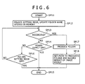
- FIG. 6 is a flow chart illustrating a procedure of a series of processes for the production of a folder.
- the MPU 3 advances the processing from step SP11 to step SP12, at which it sets the operation mode to the folder setting mode and updates the folder name stored into the memory upon turning on of the power supply in a similar manner as at step SP2 of FIG. 4.
- step SP13 the MPU 3 advances the processing to step SP14, at which it decides whether or not an instruction to record a result of image pickup is issued by an operation of the operation element by the user. If a negative result is obtained at step SP13, then the processing advances to step SP14. Here, the MPU 3 decides whether or not an operation to turn off the power supply is performed. If an affirmative result is obtained at step SP14, then the processing advances to step SP15, at which the processing procedure is ended. However, if a negative result is obtained at step SP14, then the processing advances from step SP14 to step SP16, at which the MPU 3 decides whether or not the folder setting mode is canceled by an operation of the folder switch 14 by the user.
- step S16 If an affirmative result is obtained at step S16, then the MPU 3 advances the processing from step SP16 to step SP15, at which it ends the processing procedure. However, if a negative result is obtained at step SP16, then the processing returns from step SP16 to step SP13. Consequently, the MPU 3 waits for an instruction to record a result of image pickup. Then, if an instruction to record a result of image pickup is issued, then the processing advances from step SP13 to step SP17, at which the MPU 3 produces a folder of the folder name recorded in the memory through the file system on the optical disk 12. Then at step SP18, the MPU 3 sets a path to the folder of the folder name and issues an instruction to record a result of image pickup.
- the MPU 3 produces a folder of the folder name below the folder of moving pictures and records the result of image pickup into the folder.
- the MPU 3 produces a folder of the folder name below the folder of still pictures and records still pictures into the folder.
- the value of the numeral of three digits for the file name described hereinabove is initialized to the value 000 to set the file name.
- the MPU 3 produces a folder using an operation of the folder switch as a trigger and records a result of image pickup into the folder. Then, when recording of the result of image pickup is completed, the processing advances to step SP15 to end the processing procedure. Consequently, a folder is produced with an intention of the user reflected thereon.
- the MPU 3 After the MPU 3 produces a new folder in one of the folder of moving pictures and the folder of still pictures by execution of the processing procedure illustrated in FIG. 4 or 6, it sets a path to the folder and records a file into the folder upon later recording of a result of image pickup in the form of moving pictures or still pictures. On the other hand, in the ordinary operation mode, a file based on a corresponding result of image pickup is recorded immediately below the folder of moving pictures or the folder of still pictures.
- the MPU 3 issues an instruction to reproduce a file recorded on the optical disk 12 to the medium interface 10 and, as a result, issues an instruction to the DSP 6 and so forth to process streaming data outputted from the medium interface 10. Consequently, in the video disk apparatus 1, a result of image pickup recorded on the optical disk 12 can be confirmed through the sound outputting section 9.
- the MPU 3 successively reproduces the files from the folder produced latest based on the folder name and provides the reproduced files to the user. Further, if an operation element for skipping is operated by the user in a state wherein a file is being produced in this manner, then the reproduction of the file being currently reproduced is stopped and the object of reproduction is changed over to a next file.
- a selection operation of files by the user is simplified by file management based on folders produced reflecting an intention of the user thereon by reproducing the files recorded on the optical disk 12 in a reverse order on the time base.
- a result of image pickup in the form of moving pictures or still pictures acquired by the camera section 2 is processed by the DSP 6 together with sound data acquired by the sound inputting section 7 and is recorded on the optical disk 12 through the medium interface 10. Consequently, the result of image pickup is recorded in a file format on the optical disk 12. Further, the result of image pickup recorded in this manner is reproduced by the optical disk 12 and inputted from the medium interface 10 to the DSP 6. Then, the result of image pickup is decoded by the DSP 6 and outputted from the display section 5 and the sound outputting section 9. Consequently, the video disk apparatus 1 can reproduce the result of image pickup recorded on the optical disk 12 so that it may be confirmed.
- results of image pickup in the form of moving pictures are recorded under the folder of moving pictures in which files of moving pictures are collected while results of image pickup in the form of still pictures are recorded under the folder of still pictures in which files of still pictures are collected. Consequently, moving pictures and still pictures are managed separately to enhance the convenience to the user. Further, the files of moving pictures and the files of still pictures are individually recorded with file names based on serial numbers, and the files can be managed with reference to the file names.
- a folder can be produced in response to a delimiter in image pickup, and the convenience in use to the user in file management can be enhanced as much.
- moving pictures and still pictures can be managed separately to produce a folder on which an intention of the user is reflected for each of moving pictures and still pictures to record a result of image pickup.
- a folder of moving pictures and a folder of still pictures are formed corresponding to recording of results of image pickup below folders DCF001, DCF002 and DCF003 produced by a folder switch as shown in FIG. 7, and results of image pickup in the form of moving pictures and still pictures are recorded in the folder of moving pictures and the folder of still pictures, respectively.
- the present embodiment is configured similarly to the embodiment 1 described hereinabove except that processes relating to the folders are different.
- the disk apparatus described hereinabove with reference to FIG. 2 records an index file on the optical disk 12 and manages various files recorded on the optical disk 12 through the index file. It is to be noted that, since the video disk apparatus according to the present embodiment is configured similarly to the video disk apparatus according to the embodiment 1 except that it is different in configuration relating to the index file, in the following description, the configuration of FIG. 2 is referred to suitably.
- a result of image pickup is recorded in a Quick Time (hereinafter referred to as QT) file format on the optical disk 12.
- QT Quick Time
- the QT format here is a file format created as an extension function of an OS (Operating System) for reproducing moving pictures and so forth without using special hardware.
- the QT format is a time-based multimedia file format which allows actual data of various forms such as moving pictures, sound, still pictures, characters, and MIDI to be reproduced in synchronism with each other on the same time base.
- the QT format is compatible also with streaming on a network.
- the DSP 6 outputs, upon recording, video data and audio data outputted from the video interface 4 and the audio interface 8 in the QT format to the medium interface 10 so that they are recorded on the optical disk 12.
- the DSP 6 processes reproduction data of the QT format outputted from the medium interface 10 and outputs resulting data to the video interface 4 and the audio interface 8.
- the MPU 3 acquires various kinds of information relating to such processes of the DSP 6 upon recording and reproduction and outputs the acquired information to the DSP 6. Further, as regards the QT files relating to results of image pickup, the MPU 3 records results of image pickup in the form of moving pictures and still pictures into the folder of moving pictures and the folder of still pictures provided on the optical disk 12, respectively. Further, at this time, the MPU 3 provides numerical values, which increase successively, for the files to set file names. Consequently, the video disk apparatus 1 merely records moving pictures and still pictures collectively into the individually corresponding folders on the optical disk 12.
- the index file is a file in which information necessary for reproduction such as the address of the recording position, the file name and the file length is managed by the file management system of the optical disk 12 similarly to a file (hereinafter referred to as QT file) of the QT format recorded on the optical disk 12 in such a manner as described above.
- the index file includes information for introduction of the substance of QT files which are an object of management recorded on the optical disk 12 and other necessary information. Consequently, the video disk apparatus 1 selects one of the QT files recorded on the optical disk 12 through the index file and reproduces the selected file from the optical disk 12 based on the file management system. Therefore, even where a large number of QT files are recorded on the optical disk 12, a desired file can be selected rapidly and accurately, and the operability can be enhanced as much.
- the index file is formed from a series of entries each in the form of a block of information (hereinafter referred to as extract information) extracted from information relating to the QT files and allocated to information which introduces the substance of the QT files and so forth. Consequently, the substance of each QT movie file can be grasped simply, easily and rapidly from the index file.
- extract information a block of information
- the index file is produced in a file structure same as that of the QT files recorded on the optical disk 12 and includes data of the extract information classified and grouped for each attribute. Consequently, the index file can be produced and processed making use of the configuration of the video disk apparatus 1 which produces QT files, and the video disk apparatus 1 can be simplified in configuration as much.
- the index file is configured such that extract information according to actual data is grouped and allocated to a text entry file E1, a thumbnail image entry file E2 and a property entry file E3.
- the index file includes the entry files E1 to E3 and a resource file (not shown) including management information for the entry files E1 to E3.
- management information of the starting positions of slots and so forth of the entry files E1 to E3 is recorded together with attribute information and so forth of the index file.
- each of the entry files E1 to E3 is formed such that a header TXH, THH or PH indicative of an attribute or the like of the entry file E1 to E3 is provided at the top thereof and is followed successively by entries each in the form of a slot of a fixed length.
- the text entry file E1 is formed such that data representative of character strings of a disk title and titles relating to management object files and so forth is successively allocated to slots so that the text entry file E1 is formed from a series of entries of the data of the titles.
- the thumbnail image entry file E2 is formed such that thumbnail images formed as still images representative of the substance of the disk title and the management object files are successively allocated to slots so that the thumbnail image entry file E2 is formed from a series of entries of the thumbnail images.
- each slot is formed with a fixed length, and consequently, one or a plurality of slots are allocated to one management object file in response to the data amount of corresponding extract information obtained from the management object file. Further, depending upon the type of the management object file, no entry may sometimes be provided because the type of the extract information is different.
- the property entry file E3 is formed such that data representative of the attribute of the disk title and the management object files is allocated thereto and extract information in the form of binary data set to the disk title and the management object files is successively allocated to slots together with management information of the entries so that the property entry file E3 is formed from a series of entries of the extract information.
- the property entry file E3 is formed of each slot with a fixed length in the similar manner as the text entry file E1 and the thumbnail image entry file E2 described above. Further, the property entry file E3 is provided without fail even if the types of the management object files are different.
- the entries of the management object files are set so as to correspond to the entries provided in the text entry file E1 and the thumbnail image entry file E2.
- corresponding extract information of one management object file is allocated to one or a plurality of slots in response to the data amount of the corresponding extract information.
- the index file portions thereof for actual data are formed with a fixed length so that useless consumption of the recording medium can be reduced and the number of times of accessing to the recording medium can be reduced to decrease the processing time.
- management information (information representative of association indicated by an arrow mark in FIGS. 8 (A) to 8 (C) which specifies a corresponding entry of a different entry file is set as management information of an entry indicative of a relationship to a different entry is set. Further, for an entry which includes a plurality of slots, management information relating to an extension slot which specifies successively appearing entries is set. Consequently, in the index file, management information representative of a relationship to a different entry set to the property entry file E3 is used to specify a plurality of slots in which extract information of one management object file is recorded. Further, in the property entry file E3, information for specifying a corresponding management object file is set, and consequently, a management object file of extract information recorded in the index file is specified by the information.
- management information in the form of validity information representative of whether extract information registered in each entry is valid or invalid is set. Consequently, only by setting the validity information provided in the property entry, the index file sets corresponding entries of the property entry file E3 and the other entry files E1 and E2 collectively to invalid thereby to delete the registration of the management object file in the index file.
- the index file allows registration not only of a file existing on the recording medium but also of an existing folder or a virtual folder by the file management system of the recording medium into each entry file, and in each property entry, a hierarchical structure of property entries in which such folders are registered can be defined. Consequently, the index file manages files recorded on the optical disk 12 in accordance with a folder structure by an existing hierarchical structure set to the optical disk 12 and further in accordance with a folder structure according to a virtual hierarchical structure set in the index file.
- the index file can provide thumbnail images to the user using the thumbnail image entry file E2 or provide titles and so forth of files to the user using the text entry file E1, accept selection of a file based on the thumbnail images and the titles, and detect the selected file depending upon the file name by the file management system from the description of the property entry. From this, the operability by the user can be enhanced.
- the MPU 3 acquires and decodes video data and audio data in the form of compressed data from the DSP 6 and, with regard to the video data, produces a thumbnail image by thinning pixels and produces the thumbnail image entry file E2 from such thumbnail images. Further, the MPU 3 produces data of a title from the file information of each of the management object files held by the file management system of the optical disk 12 and based on a setting of the user and produces the text entry file E1 from the thus produced data. Further, in response to an operation of the user, the MPU 3 produces the property entry file E3 and produces the resource file in response to the entry files E1 to E3.
- the property entry file E3 has a hierarchical structure defined in accordance with such settings as illustrated in FIGS. 9(A) and 9(B). It is to be noted that, in the following description, only a case wherein an extension slot is not set is described for the simplified description, and each of folders and files is indicated by a slot number of a corresponding slot set therefore. Then, where an extension slot to a slot of a property entry exists or where a slot corresponding to another entry exists, a process for the slots of the property entry described below is executed for a lump of the relating slots.
- an entry number (Entry Number) for specifying each slot is set.
- an entry property flag (Entry Property) in the form of a set of a plurality of flags is set.
- the entry property flag (Entry Property) here, various kinds of information each representative of an attribute of an entry are set, and as one of the flags, an entry property flag is set for identification of whether the slot corresponds to a folder (0: Folder) or corresponds to a file (1: File).
- a property entry of the entry number 0 is allocated to the existing root folder 0 by the file management system of the optical disk 12, and the entry property flag is set to the value 0 so that it can be discriminated that the property entry is an entry of a folder.
- property entries of the entry numbers 1, 2, 3 and 4 are allocated, respectively, and the entry property flags are set to the value 0 and the value 1 so that it can be discriminated that the property entries are folders and files, respectively.
- property entries of the entry numbers 5 and 6 are allocated, and the entry property flags are set to the value 0 and the value 1 so that it can be discriminated that the property entries are a folder and a file, respectively.
- the file 7 which belongs to the folder 5 a property entry of the entry number 7 is allocated, and the entry property flag is set to the value 1 so that it can be discriminated that the property entry is a file.
- a parent entry number (Parent Entry Number) indicative of a slot corresponding to the nearest folder to which the corresponding file or folder belongs is allocated to the property entry file E3 as management information representative of a relationship of the entry to another entry. Consequently, in the example shown in FIGS. 9 (A) and 9(B), for the entries of the entry numbers 1 to 4, the parent entry number (Parent Entry Number) is set to the value 0 so as to indicate that the folders 1 and 2 and the files 3 and 4 of the entry numbers 1 to 4 belong to the root folder.
- the parent entry number (Parent Entry Number) is set to the value 1
- the parent entry number (Parent Entry Number) is set to the value 5. Consequently, it is indicated that the corresponding folder 5, file 6 and file 7 belong to the folder 1, folder 1 and folder 5, respectively.
- a child entry number indicating the lower side from the higher side is registered additionally so that a file or the like which belongs to a particular folder can be searched out simply and easily from the child entry number.
- the entry numbers 1, 2, 3 and 4 indicative of the entries of the folders 1 and 2 and the files 3 and 4 are registered as child entry numbers.
- the entry numbers 5 and 6 indicative of the entries of the folder 5 and the file 6 are registered as child entry numbers, and for the entry number 5, the child entry number of the entry number 7 is registered.
- the files can be managed in accordance with a hierarchical structure which actually exists in the file management system and further with a virtual hierarchical structure. It is to be noted that, in the following description, information indicative of another entry according to such a definition of a hierarchical structure as described above is referred to as hierarchical information.
- the MPU 3 builds up the hierarchical structure described hereinabove with reference to FIG. 5 or 7 in response to turning on of the power supply or an operation of the folder switch 14 based on a virtual hierarchical structure by such settings of entries in the property entry file E3 as described above.
- the MPU 3 registers a temporary entry into the index file by setting the hierarchical information so that the entry may belong to the root folder. Further, in the example of FIG. 5, the hierarchical information of an entry of a folder of moving pictures or still pictures is set so that the entry belongs to a virtual folder of the temporary entry when the entry is registered into the index file. Consequently, the index file for management of a result of image pickup is produced and recorded on and retained by the optical disk 12.
- the MPU 3 accesses the optical disk 12 through the medium interface 10 in response to turning on of the power supply or in response to loading of the optical disk 12 to reproduce the index file and stores various kinds of management information into the memory built therein. After the management information is stored into the memory in this manner, the MPU 3 detects an entry of a folder in which the latest result of image pickup is recorded from among results of image pickup recorded on the optical disk 12 and detects the folder name of the folder from the description of the text entry file of the entry or from the registration of the entry. Further, the MPU 3 updates the detected folder name and registers an entry of a virtual folder of moving pictures or still pictures into the index file by setting the hierarchical information so that the folder of the updated folder name may belong to the virtual folder. Also, the MPU 3 registers an entry of files according to the result of an image pickup by setting the hierarchical information so that the files may belong to this folder.
- files according to the results of image pickup are successively registered into the index file by setting the hierarchical information so that the files may belong to the virtual folder produced in this manner.
- the folder switch 14 is operated by the user, then an entry of the folder is registered into the index file in a similar manner, and a file according to a result of image pickup is recorded into the index file by setting the hierarchical information so that the file may belong to the entry.
- the MPU 3 processes the index file by setting an entry so as to be compatible with the hierarchical structure shown in FIG. 7.
- the MPU 3 displays a virtual hierarchical structure through an analysis of the index file and accepts selection of a file of a reproduction object by selection of the user in the hierarchical structure. Further, if the user issues a reproduction instruction without selecting any file, then the files recorded on the optical disk 12 are successively reproduced and provided to the user in an order reverse to the recording order depending upon the records of the index file.
- the hierarchical structure can be defined suitably for an application of the video disk apparatus 1.
- the operation mode is changed over by means of the folder switch to the folder setting mode in which a folder is produced and a result of image pickup is recorded
- the present invention is not limited to this, and the changeover of the operation mode by means of the folder switch may be omitted.
- a folder is changed over in accordance with a virtual hierarchical structure in which the index file is used to record a result of image pickup
- the present invention is not limited to this, but even where the index file is used, a folder may be produced in accordance with an existing hierarchical structure to record a result of image pickup.
- the present invention is not limited to this but can be applied widely also to a case wherein the index file is produced in accordance with a so-called internal reference form wherein a source file and a file formed from extract information are collected into a single file. Furthermore, the present invention can be applied widely also to a case wherein the index file is formed in a format other than the QT file format.
- the present invention is not limited to this but can be applied widely to various apparatus which record a result of image pickup on a recording medium such as a portable telephone set and PDAs (Personal Digital Assistants) which have an image pickup function.
- a recording medium such as a portable telephone set and PDAs (Personal Digital Assistants) which have an image pickup function.
- the present invention can be applied, for example, to a video disk apparatus.
Landscapes
- Engineering & Computer Science (AREA)
- Signal Processing (AREA)
- Information Retrieval, Db Structures And Fs Structures Therefor (AREA)
- Management Or Editing Of Information On Record Carriers (AREA)
- Processing Or Creating Images (AREA)
- Television Signal Processing For Recording (AREA)
Applications Claiming Priority (2)
| Application Number | Priority Date | Filing Date | Title |
|---|---|---|---|
| JP2003345814A JP2005115998A (ja) | 2003-10-03 | 2003-10-03 | ファイル管理装置、ファイル管理方法、ファイル管理方法のプログラム及びファイル管理方法のプログラムを記録した記録媒体 |
| PCT/JP2004/013287 WO2005034126A1 (ja) | 2003-10-03 | 2004-09-07 | ファイル管理装置、ファイル管理方法、ファイル管理方法のプログラム及びファイル管理方法のプログラムを記録した記録媒体 |
Publications (1)
| Publication Number | Publication Date |
|---|---|
| EP1675124A1 true EP1675124A1 (de) | 2006-06-28 |
Family
ID=34419473
Family Applications (1)
| Application Number | Title | Priority Date | Filing Date |
|---|---|---|---|
| EP04772969A Withdrawn EP1675124A1 (de) | 2003-10-03 | 2004-09-07 | Dateiverwaltungseinrichtung, dateiverwaltungsverfahren, programm eines dateiverwaltungsverfahrens und aufzeichnungsmedium, das das programm des dateiverwaltungsverfahrens enthält |
Country Status (6)
| Country | Link |
|---|---|
| EP (1) | EP1675124A1 (de) |
| JP (1) | JP2005115998A (de) |
| KR (1) | KR20060089733A (de) |
| CN (1) | CN1864224A (de) |
| TW (1) | TW200521990A (de) |
| WO (1) | WO2005034126A1 (de) |
Cited By (1)
| Publication number | Priority date | Publication date | Assignee | Title |
|---|---|---|---|---|
| EP1923791A4 (de) * | 2005-08-26 | 2010-11-24 | Panasonic Corp | Datenaufzeichnungssystem, datenaufzeichnungsverfahren und datenaufzeichnungsprogramm |
Families Citing this family (6)
| Publication number | Priority date | Publication date | Assignee | Title |
|---|---|---|---|---|
| US20070014543A1 (en) | 2005-07-13 | 2007-01-18 | Canon Kabushiki Kaisha | Image processing apparatus and control method therefor |
| JP4735151B2 (ja) * | 2005-09-16 | 2011-07-27 | カシオ計算機株式会社 | カメラ装置、画像記録方法及び画像表示方法 |
| JP5112327B2 (ja) * | 2005-11-17 | 2013-01-09 | コーニンクレッカ フィリップス エレクトロニクス エヌ ヴィ | 独自仕様のデータを管理するシステム |
| JP4693651B2 (ja) * | 2006-02-20 | 2011-06-01 | キヤノン株式会社 | 撮像装置及びその制御方法 |
| JP5149570B2 (ja) | 2006-10-16 | 2013-02-20 | キヤノン株式会社 | ファイル管理装置、ファイル管理装置の制御方法、及びプログラム |
| CN103309876A (zh) * | 2012-03-12 | 2013-09-18 | 腾讯科技(深圳)有限公司 | 创建文件夹的方法和装置 |
Family Cites Families (7)
| Publication number | Priority date | Publication date | Assignee | Title |
|---|---|---|---|---|
| JP3816219B2 (ja) * | 1997-12-01 | 2006-08-30 | 富士写真フイルム株式会社 | 電子カメラ |
| JP4505870B2 (ja) * | 1999-03-31 | 2010-07-21 | ソニー株式会社 | 記録再生装置 |
| JP2002112077A (ja) * | 2000-09-27 | 2002-04-12 | Sanyo Electric Co Ltd | デジタルカメラ |
| JP2002149458A (ja) * | 2000-11-13 | 2002-05-24 | Matsushita Electric Ind Co Ltd | 情報処理装置及び画像処理装置 |
| JP2002191010A (ja) * | 2000-12-20 | 2002-07-05 | Matsushita Electric Ind Co Ltd | デジタルスチルカメラ |
| JP3682235B2 (ja) * | 2001-02-08 | 2005-08-10 | 株式会社ケンウッド | データ再生装置、データ再生方法、及び、プログラム |
| JP2002278996A (ja) * | 2001-03-22 | 2002-09-27 | Sony Corp | 記録装置および記録方法、並びに記録媒体 |
-
2003
- 2003-10-03 JP JP2003345814A patent/JP2005115998A/ja active Pending
-
2004
- 2004-09-07 WO PCT/JP2004/013287 patent/WO2005034126A1/ja active Application Filing
- 2004-09-07 KR KR1020067006443A patent/KR20060089733A/ko not_active Application Discontinuation
- 2004-09-07 EP EP04772969A patent/EP1675124A1/de not_active Withdrawn
- 2004-09-07 CN CNA2004800288371A patent/CN1864224A/zh active Pending
- 2004-10-01 TW TW093129748A patent/TW200521990A/zh unknown
Non-Patent Citations (1)
| Title |
|---|
| See references of WO2005034126A1 * |
Cited By (3)
| Publication number | Priority date | Publication date | Assignee | Title |
|---|---|---|---|---|
| EP1923791A4 (de) * | 2005-08-26 | 2010-11-24 | Panasonic Corp | Datenaufzeichnungssystem, datenaufzeichnungsverfahren und datenaufzeichnungsprogramm |
| US8028004B2 (en) | 2005-08-26 | 2011-09-27 | Panasonic Corporation | Data recording system, data recording method and data recording program |
| US8732210B2 (en) | 2005-08-26 | 2014-05-20 | Panasonic Corporation | Data recording system, data recording method and data recording program |
Also Published As
| Publication number | Publication date |
|---|---|
| TW200521990A (en) | 2005-07-01 |
| JP2005115998A (ja) | 2005-04-28 |
| WO2005034126A1 (ja) | 2005-04-14 |
| KR20060089733A (ko) | 2006-08-09 |
| CN1864224A (zh) | 2006-11-15 |
Similar Documents
| Publication | Publication Date | Title |
|---|---|---|
| US7809728B2 (en) | Recording/playback apparatus and method | |
| US7599906B2 (en) | File management device, file management method, file management method program, and recording medium the file management method program | |
| US20030202431A1 (en) | Method for managing summary information of play lists | |
| US20070112785A1 (en) | System and method for updating a storage medium | |
| KR20000017047A (ko) | 기록매체, 기록장치, 재생장치, 기록방법, 및 컴퓨터가 읽기가능한 기록매체 | |
| CN101154419B (zh) | 记录和再现装置及内容管理方法 | |
| JP2005044367A (ja) | 画像メタデータがロードされる画像取込み装置 | |
| EP1921626A1 (de) | Aufnahmevorrichtung, aufnahmeverfahren, wiedergabevorrichtung, wiedergabeverfahren, programm und aufnahmemedium | |
| EP1675124A1 (de) | Dateiverwaltungseinrichtung, dateiverwaltungsverfahren, programm eines dateiverwaltungsverfahrens und aufzeichnungsmedium, das das programm des dateiverwaltungsverfahrens enthält | |
| US7610262B2 (en) | File management device | |
| JP4393320B2 (ja) | ファイル管理装置及びその制御方法並びに記録装置 | |
| US20060259512A1 (en) | File management apparatus file management method program of file management method and recording medium on which program of file management method is recorded | |
| US7675827B2 (en) | Information processing apparatus, information processing method, and program | |
| US20070168386A1 (en) | Device and method for managing multimedia content in portable digital apparatus | |
| JP2000134565A (ja) | 記録媒体、記録装置、再生装置、記録方法、及びコンピュ―タ読みとり可能な記録媒体 | |
| WO2005006335A1 (en) | Recording/playback apparatus and method | |
| JP2003223345A (ja) | ファイル表示装置 | |
| JPH09307851A (ja) | 画像及び音声の記録管理装置及び方法 | |
| JP2005135554A (ja) | 再生装置及び方法 | |
| JP3530857B2 (ja) | 電子的撮像装置 | |
| JP3442765B2 (ja) | 電子的撮像装置 | |
| JPH03154967A (ja) | 情報検索装置 | |
| JP2001069461A (ja) | 再生装置、再生方法、およびコンピュータ読み取り可能な記録媒体 | |
| JP2002300530A (ja) | 記録方法、記録装置およびコンピュータ読み取り可能な記録媒体 | |
| JP2005166131A (ja) | 再生装置及び制御プログラム並びに記録媒体 |
Legal Events
| Date | Code | Title | Description |
|---|---|---|---|
| PUAI | Public reference made under article 153(3) epc to a published international application that has entered the european phase |
Free format text: ORIGINAL CODE: 0009012 |
|
| 17P | Request for examination filed |
Effective date: 20060315 |
|
| AK | Designated contracting states |
Kind code of ref document: A1 Designated state(s): DE FR GB |
|
| DAX | Request for extension of the european patent (deleted) | ||
| RBV | Designated contracting states (corrected) |
Designated state(s): DE FR GB |
|
| STAA | Information on the status of an ep patent application or granted ep patent |
Free format text: STATUS: THE APPLICATION HAS BEEN WITHDRAWN |
|
| 18W | Application withdrawn |
Effective date: 20090122 |