EP1674649A1 - Zweiteiliges Laibungsanschlussprofil für an putz angrenzende Bauteile - Google Patents
Zweiteiliges Laibungsanschlussprofil für an putz angrenzende Bauteile Download PDFInfo
- Publication number
- EP1674649A1 EP1674649A1 EP05450200A EP05450200A EP1674649A1 EP 1674649 A1 EP1674649 A1 EP 1674649A1 EP 05450200 A EP05450200 A EP 05450200A EP 05450200 A EP05450200 A EP 05450200A EP 1674649 A1 EP1674649 A1 EP 1674649A1
- Authority
- EP
- European Patent Office
- Prior art keywords
- profile
- leg
- base
- luff
- plaster
- Prior art date
- Legal status (The legal status is an assumption and is not a legal conclusion. Google has not performed a legal analysis and makes no representation as to the accuracy of the status listed.)
- Granted
Links
Images

Classifications
-
- E—FIXED CONSTRUCTIONS
- E04—BUILDING
- E04F—FINISHING WORK ON BUILDINGS, e.g. STAIRS, FLOORS
- E04F13/00—Coverings or linings, e.g. for walls or ceilings
- E04F13/02—Coverings or linings, e.g. for walls or ceilings of plastic materials hardening after applying, e.g. plaster
- E04F13/04—Bases for plaster
- E04F13/06—Edge-protecting borders
- E04F13/068—Edge-protecting borders combined with mesh material or the like to allow plaster to bond therewith
-
- E—FIXED CONSTRUCTIONS
- E06—DOORS, WINDOWS, SHUTTERS, OR ROLLER BLINDS IN GENERAL; LADDERS
- E06B—FIXED OR MOVABLE CLOSURES FOR OPENINGS IN BUILDINGS, VEHICLES, FENCES OR LIKE ENCLOSURES IN GENERAL, e.g. DOORS, WINDOWS, BLINDS, GATES
- E06B1/00—Border constructions of openings in walls, floors, or ceilings; Frames to be rigidly mounted in such openings
- E06B1/62—Tightening or covering joints between the border of openings and the frame or between contiguous frames
-
- E—FIXED CONSTRUCTIONS
- E04—BUILDING
- E04F—FINISHING WORK ON BUILDINGS, e.g. STAIRS, FLOORS
- E04F13/00—Coverings or linings, e.g. for walls or ceilings
- E04F13/02—Coverings or linings, e.g. for walls or ceilings of plastic materials hardening after applying, e.g. plaster
- E04F13/04—Bases for plaster
- E04F13/06—Edge-protecting borders
- E04F2013/063—Edge-protecting borders for corners
-
- E—FIXED CONSTRUCTIONS
- E06—DOORS, WINDOWS, SHUTTERS, OR ROLLER BLINDS IN GENERAL; LADDERS
- E06B—FIXED OR MOVABLE CLOSURES FOR OPENINGS IN BUILDINGS, VEHICLES, FENCES OR LIKE ENCLOSURES IN GENERAL, e.g. DOORS, WINDOWS, BLINDS, GATES
- E06B1/00—Border constructions of openings in walls, floors, or ceilings; Frames to be rigidly mounted in such openings
- E06B1/62—Tightening or covering joints between the border of openings and the frame or between contiguous frames
- E06B2001/624—Tightening or covering joints between the border of openings and the frame or between contiguous frames with parts to be embedded in the stucco layer or otherwise linked to this layer
Definitions
- the invention relates to a two-part soffit connection profile for components adjacent to plaster, in particular for window or door frames, with a base profile, which can be fastened to the component, and a movable by the base profile outer profile, which has a Einputzschenkel.
- sealing tapes or self-adhesive sealing compounds with which the soffit connection profiles are fastened to the window or door frame.
- the relative movements can only be compensated to a very limited extent by the sealing bands.
- the extensibility of the sealing strip is about 25% of the sealing strip thickness.
- a sealing tape of 4 mm thickness may e.g. Move the facade away from the window or door frame only to the extent of approx. 1 mm.
- partially expanding sealing strips or profiles with expanding sealing strips are used in facade construction, but because of the thickness of the sealing strip they are visually unsightly, as well as relatively expensive and complicated to install.
- WO 97/30245 A1 a plaster strip for window bars, door frames or the like at the transition to plaster has become known, which consists of a U-shaped base portion, which is fastened by means of an adhesive tape on the window sill.
- a likewise substantially U-shaped front portion is attachable, wherein a plug connection in the manner of a telescopic pair allows a relative movement between the base region and the front region.
- EP 0 801 189 B1 further discloses a soffit connection profile which has an inner frame fastening leg and an opposite outer leg with a vertically angled plastered web, wherein the frame fastening leg and the outer leg are spaced apart by two Connecting webs of elastically bendable material are interconnected such that the legs are parallel to each other and perpendicular to each other displaced.
- the frame attachment leg is attached to the window floor with adhesive tape.
- EP 0 716 204 A2 discloses a two-part soffit connection profile for sealing a frame part with respect to a soffit, which has a base profile which can be fastened to the component with the aid of an adhesive strip, in the longitudinal groove of which the spring of an outer profile is movably guided.
- the plane of movement of the tongue and groove joint is parallel to the plane of the fixture, so that only relative movements in this plane can be effectively compensated.
- a similar tongue and groove joint of a two-part trim edge profile is known from DE 40 17 250 A1, and serves to compensate for plaster edges in roller shutter boxes.
- a soffit profile for attachment of a covering material has become known at a building opening, which is made in two parts and consists of a mounting profile strip and an associated outer profile strip.
- Both the fastening profile strip and the outer profile strip are U-shaped in cross-section, so that the legs of the fastening profile strip and the legs of the outer profile strip interlock.
- the individual legs of the two U-shaped strips have mutually directed sealing lips, so that moisture can not penetrate from the outside into the space enclosed by the profile strips.
- the plane of movement of the two U-profiles lies parallel to the plane of the built-in part, so that relative movements in this plane can be compensated.
- a low mobility is also perpendicular to the mounting plane, since the sealing lips are made of an elastic material.
- the disadvantage is the fact that the outer profile can not be inserted into the fastening profile after the attachment of an insulating layer, and that the outer profile strip forms a visible gap to the mounting profile strip, which remains visible after the separation of a protective leg for a cover.
- the object of the invention is to propose a two-part soffit connection profile, with which, above all, when using an insulating layer on the one hand a permanent seal between plaster or Spachtelan ever and the adjacent components can be achieved and on the other hand relative movements be adequately permitted between plaster and component in all spatial directions. Furthermore, the soffit connection profile should be visually appealing and easy to manufacture and assemble.
- the outer profile has a mounting leg, which is inserted between a formed on the base profile retaining web and the component and there by means of at least one integrally formed on the base profile or the outer profile spring element is fixable.
- the outer profile is thus directly on the component and forms no visible from the front gap to a leg of the base profile.
- connection profile the insulating layer can be aligned after attachment of the base profile on the component (by gluing or screws) with the aid of the front edge of the retaining web in an advantageous manner. Subsequently, the fastening leg of the outer profile is inserted between retaining web and adjacent component.
- the base profile, the retaining web and the adjacent region of the component form an example U-shaped receiving space for the fastening leg and the at least one spring element.
- the mounting leg of the outer profile at its end facing away from Einputzschenkel a pointing towards Einputzschenkel and elastically abutting the retaining web of the base leg spring element.
- the base leg and / or the spring element can be made elastic by material selection (soft plastic) or shaping (thin cross sections).
- the two-part profile ensures sufficient freedom of movement in the plane of the component as well as in a direction perpendicular to the component plane, since the spring element is yielding in a direction perpendicular to the component plane.
- the mounting leg of the outer profile is substantially normal to the Einputzschenkel and has in the direction of component projecting sealing webs. These may be elastic, so that a range of motion perpendicular to the component level is available.
- the fastening leg in the direction of the retaining web of the base profile projecting spring elements in the form of sealing lips, which preferably consist of a softer material and are produced by post or co-extrusion.
- spring elements - also in the form of sealing lips - to provide on the holding web of the base profile, which protrude in the direction of the mounting leg of the outer profile.
- the Einputzschenkel the outer profile on the base profile side facing an adhesive tape for fixing the outer profile of an insulating layer.
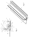
- the two-part soffit connection profile 1 shown in FIGS. 1 and 2 for components 11 adjacent to the plaster 10 has a base profile 2, which is provided on the component side with a self-adhesive sealing strip 22 and thus fastened to the component 11. As indicated by dashed lines, the base profile 2 can also be screwed, for which holes 20 are provided.
- the outer profile 3 of the soffit connection profile 1 has a plaster leg 4 and a fastening leg 5, the latter being insertable between a retaining web 6 formed on the base profile 2 and the component 11 and being fixed there by means of at least one spring element 7 formed on the outer profile 3.
- the base profile 2 is first glued to the component 11 and possibly additionally screwed on. Thereafter, the insulating layer 13 is used, wherein the front edge of the retaining web 6 serves as an alignment aid for the insulating layer 13. Thereafter, the outer profile 3 is inserted with its mounting leg 5 in the formed by the base profile 2, the retaining web 6 and the adjacent region of the component 11, substantially U-shaped receiving space and the Einputzschenkel 4 by means of arranged on the back of the adhesive tape 12 on the Insulating layer 13 fixed. After installation of the connection profile 1, its outer leg 3 can compensate for both movements in the plane of the component 11 and tensile movements (away from the installation part 11).
- the outer leg 3 in the direction of the component 11 projecting sealing webs 8, 9, wherein a sealing web 8 is arranged in extension of the plaster leg 4 and another 9 is formed in the central region of the mounting leg 5.
- the base leg 5 and / or the spring element 7 are made elastic by material selection or shaping.
- the retaining web 6 of the base profile 2 may have a projecting in the direction of component 11 retaining edge 21 for securing the outer profile 3.
- the elastic spring element 7 snaps over the retaining edge 21 and then abuts the retaining web 6 of the base profile 2.
- the outer profile 3 has a plaster web 17, which together with the Einputzschenkel 4 forms a Putzabilityraum.
- the outer profile 3 is provided to protect the component 11 during the plastering work with a detachable protective leg 18 for receiving a cover, which is preferably secured via a predetermined breaking point 19 on the plaster web 17.
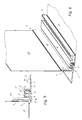
- the embodiment according to FIG. 3 and FIG. 4 differs from the one described above essentially only in that a protective film 16 is attached to the plastering leg 4 of the outer profile 3, which is glued onto the insulating layer and subsequently overprepared. Such a protective film 16 prevents the penetration of water in this sensitive connection area. It is of course also possible to equip the Einputzschenkel 4 with a reinforcing fabric (see Fig. 8). As shown in FIG. 3, the base profile 2 may have at least one sealing lip 24 on the side facing the component 11.
- the fastening leg 5 of the outer profile 3 is essentially normal to the plastered leg 4 and has sealing webs 8, 9 projecting in the direction of the component 11, which in the installed state of the reveal connection profile 1 rest on the component 11, wherein at least one of the sealing webs 8, 9 can also be designed as a sealing lip.
- projecting spring elements 7 ' are formed in the form of elastic sealing lips, which preferably consist of a softer material and are prepared by post or co-extrusion.
- the sealing lips 7 ' are deformable, whereby a range of motion is given in all three spatial directions.
- the base profile 2 may have a protective film 23 on the side remote from the outer profile 3, which is fastened to the masonry, for example glued, in order to provide a better seal in this area.
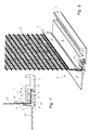
- the retaining web 6 of the base profile 2 can also have spring elements 7 'projecting in the direction of the fastening leg 5 of the outer profile 3 in the form of sealing lips, which likewise may preferably consist of a softer material.
- the fastening leg 5 and the plastering leg 4 of the outer profile 3 have a retaining tab 14 for fastening a reinforcing fabric 15.
- the retaining tab 14 can also serve for fastening a protective film 16 (see FIG. 4), or receive both a protective film and a reinforcing fabric.
Landscapes
- Engineering & Computer Science (AREA)
- Architecture (AREA)
- Civil Engineering (AREA)
- Structural Engineering (AREA)
- Building Environments (AREA)
- Door And Window Frames Mounted To Openings (AREA)
- Prostheses (AREA)
- Absorbent Articles And Supports Therefor (AREA)
- Vehicle Interior And Exterior Ornaments, Soundproofing, And Insulation (AREA)
Abstract
Description
- Die Erfindung betrifft ein zweiteiliges Laibungsanschlussprofil für an Putz angrenzende Bauteile, insbesondere für Fenster- oder Türstöcke, mit einem Basisprofil, welches am Bauteil befestigbar ist, und einem durch das Basisprofil beweglich fixierbaren Außenprofil, welches einen Einputzschenkel aufweist.
- Bei vielen Laibungsanschlussprofilen müssen Relativbewegungen zwischen dem angrenzenden Einbauteil und der Fassade durch Dichtungsbänder bzw. selbstklebende Dichtungsmassen aufgenommen werden, mit welchen die Laibungsanschlussprofile am Fenster- oder Türstock befestigt werden. Die Relativbewegungen können allerdings von den Dichtungsbändern nur sehr eingeschränkt kompensiert werden. Üblicherweise liegt die Dehnungsfähigkeit des Dichtungsbandes bei ca. 25% der Dichtungsbandstärke. Ein Dichtungsband mit 4 mm Stärke kann so z.B. Bewegungen der Fassade weg vom Fenster- oder Türstock lediglich im Ausmaß von ca. 1 mm aufnehmen. Zum Ausgleich größerer Relativbewegungen werden im Fassadenbau teilweise expandierende Dichtungsbänder bzw. Profile mit expandierenden Dichtungsbändern (z.B. Firma ILLBRUCK, D-51381 Leverkusen) verwendet, diese sind jedoch aufgrund der Dicke des Dichtungsbandes optisch unansehnlich, so wie relativ teuer und kompliziert beim Einbau.
- In diesem Zusammenhang ist aus der WO 97/30245 A1 eine Anputzleiste für Fensterstöcke, Türstöcke oder dergleichen am Übergang zu Putz bekannt geworden, welche aus einem U-förmigen Basisbereich besteht, welcher mittels eines Klebebandes am Fensterstock befestigbar ist. Auf den Basisbereich der Anputzleiste ist ein ebenfalls im Wesentlichen U-förmiger Vorderbereich aufsteckbar, wobei eine Steckverbindung nach Art eines Teleskopaares eine Relativbewegung zwischen dem Basisbereich und dem Vorderbereich zulässt. Dadurch können zwar Bewegungen des Fensterstockes, beispielsweise verursacht durch Winddruck, sowie Relativbewegungen längs der Profilachse ausgeglichen werden, nicht jedoch in die dritte Raumrichtung.
- Aus der EP 0 801 189 B1 ist weiters ein Laibungsanschlussprofil bekannt, welches einen inneren Rahmenbefestigungsschenkel sowie einen gegenüberliegenden Außenschenkel mit einem senkrecht abgewinkelten Einputzsteg aufweist, wobei der Rahmenbefestigungsschenkel und der Außenschenkel durch zwei beabstandete Verbindungsstege aus elastisch verbiegbarem Material derart miteinander verbunden sind, dass die Schenkel parallel zueinander und senkrecht gegeneinander verschiebbar sind. Der Rahmenbefestigungsschenkel wird mit einem Klebeband am Fensterstock befestigt. Nachteile bestehen vor allem darin, dass zwar Relativbewegungen in der Fensterebene, nicht jedoch in vertikaler Richtung vom Fensterstock wegführende Zugbelastungen vom Anschlussprofil in ausreichendem Ausmaß aufgenommen werden können, sodass es zu Ablösungen im Klebebereich kommen kann. Weiters bleiben relativ große Flächen des Anschlussprofils nach dem Einbau sichtbar.
- Aus der EP 0 716 204 A2 ist ein zweiteiliges Laibungsanschlussprofil zum Abdichten eines Rahmenteils gegenüber einer Laibung bekannt, welches ein am Bauteil mit Hilfe eines Klebestreifens befestigbares Basisprofil aufweist in dessen Längsnut die Feder eines Außenprofils beweglich geführt ist. Die Bewegungsebene der Nut/Federverbindung liegt parallel zur Ebene des Einbauteils, so dass nur Relativbewegungen in dieser Ebene wirksam kompensiert werden können. Eine ähnliche Nut/Federverbindung eines zweiteiligen Putzkantenprofils ist aus der DE 40 17 250 A1 bekannt, und dient zum Ausgleich von Putzkanten bei Rollladenkästen.
- Schließlich ist aus der DE 201 03 182 U1 ein Laibungsprofil zur Befestigung eines Abdeckmaterials an einer Gebäudeöffnung bekannt geworden, welches zweiteilig ausgeführt ist und aus einer Befestigungsprofilleiste und einer damit verbundenen Außenprofilleiste besteht. Sowohl die Befestigungsprofilleiste als auch die Außenprofileiste sind im Querschnitt U-förmig ausgebildet, so dass die Schenkel der Befestigungsprofilleiste und die Schenkel der Außenprofilleiste ineinander greifen. Die einzelnen Schenkel der beiden U-förmigen Leisten weisen zueinander gerichtete Dichtlippen auf, so dass von außen keine Feuchtigkeit in den von den Profilleisten eingeschlossenen Raum eindringen kann. Die Bewegungsebene der beiden U-Profile liegt parallel zur Ebene des Einbauteils, so dass Relativbewegungen in dieser Ebene kompensiert werden können. Eine geringe Beweglichkeit besteht auch senkrecht zur Befestigungsebene, da die Dichtlippen aus einem elastischen Material bestehen. Nachteilig ist die Tatsache, dass das Außenprofil nicht erst nach der Anbringung einer Dämmschicht in das Befestigungsprofil eingeschoben werden kann, sowie dass die Außenprofilleiste einen sichtbaren Spalt zur Befestigungsprofilleiste bildet, welcher nach dem Abtrennen eines Schutzschenkels für eine Abdeckfolie sichtbar bleibt.
- Aufgabe der Erfindung ist es ein einzweiteiliges Laibungsanschlussprofil vorzuschlagen, mit welchem vor allem bei Verwendung einer Dämmschicht einerseits eine dauerhafte Abdichtung zwischen Putz- oder Spachtelanschlüssen und den angrenzenden Bauteilen erreicht werden kann und andererseits Relativbewegungen zwischen Putz und Bauteil in allen Raumrichtungen in ausreichendem Ausmaß zugelassen werden. Weiters soll das Laibungsanschlussprofil optisch ansprechend sowie einfach herstellbar und montierbar sein.
- Diese Aufgabe wird erfindungsgemäß dadurch gelöst, dass das Außenprofil einen Befestigungsschenkel aufweist, welcher zwischen einen am Basisprofil ausgebildeten Haltesteg und dem Bauteil einschiebbar ist und dort mit Hilfe zumindest eines am Basisprofil oder am Außenprofil angeformten Federelementes fixierbar ist. Das Außenprofil liegt somit direkt am Bauteil an und bildet keinen von vorne sichtbaren Spalt zu einem Schenkel des Basisprofils aus.
- Beim erfindungsgemäßen Anschlussprofil kann in vorteilhafter Weise die Dämmschicht nach der Befestigung des Basisprofils am Bauteil (durch Kleben oder Schrauben) mit Hilfe der vorderen Kante des Haltesteges ausgerichtet werden. Anschließend wird der Befestigungsschenkel des Außenprofils zwischen Haltesteg und angrenzendem Bauteil eingeschoben. Erfindungsgemäß bildet das Basisprofil, dessen Haltesteg und der angrenzende Bereich des Bauteils einen beispielsweise U-förmigen Aufnahmeraum für den Befestigungsschenkel und das zumindest eine Federelement.
- Gemäß einer ersten Ausführungsvariante der Erfindung weist der Befestigungsschenkel des Außenprofils an seinem vom Einputzschenkel abgewandten Ende ein in Richtung Einputzschenkel weisendes und am Haltesteg des Basisschenkels elastisch anliegendes Federelement auf. Erfindungsgemäß kann der Basisschenkel und/oder das Federelement durch Materialwahl (weicher Kunststoff) oder Formgebung (dünne Querschnitte) elastisch ausgeführt sein. Durch das zweiteilige Profil ist sowohl eine ausreichende Bewegungsfreiheit in der Ebene des Bauteils als auch in eine Richtung senkrecht zur Bauteilebene gewährleistet, da das Federelement in eine Richtung senkrecht zur Bauteilebene nachgiebig ist.
- Gemäß einer zweiten vorteilhaften Ausführungsvariante der Erfindung steht der Befestigungsschenkel des Außenprofils im Wesentlichen normal auf den Einputzschenkel und weist in Richtung Bauteil ragende Dichtungsstege auf. Diese können elastisch ausgebildet sein, sodass ein Bewegungsspielraum senkrecht zur Bauteilebene zur Verfügung steht.
- Weiters weist der Befestigungsschenkel in Richtung Haltesteg des Basisprofils ragende Federelemente in Form von Dichtlippen auf, welche vorzugsweise aus einem weicheren Material bestehen und durch Post- oder Co-Extrusion hergestellt sind. Natürlich ist es auch möglich derartige Federelemente - ebenfalls in Form von Dichtlippen - am Haltesteg des Basisprofils vorzusehen, welche in Richtung des Befestigungsschenkels des Außenprofils ragen.
- In einer vorteilhaften Ausführungsvariante der Erfindung weist der Einputzschenkel des Außenprofils an der dem Basisprofil zugewandten Seite ein Klebeband zur Fixierung des Außenprofils an einer Dämmschicht auf.
- Die Erfindung wird im Folgenden anhand von Zeichnungen näher erläutert. Es zeigen:
- Fig. 1
- ein erfindungsgemäßes Laibungsanschlussprofil in einer Schnittdarstellung;
- Fig. 2
- as Anschlussprofil nach Fig. 1 in einer dreidimensionalen Darstellung; sowie die
- Fig. 3
- und Fig. 4, Fig. 5 und Fig. 6 sowie Fig. 7 und Fig. 8 jeweils erfindungsgemäße Varianten des Anschlussprofils gemäß Fig. 1 und Fig. 2.
- Das in den Fig. 1 und Fig. 2 dargestellte, zweiteilige Laibungsanschlussprofil 1 für an Putz 10 angrenzende Bauteile 11 weist ein Basisprofil 2 auf, welches bauteilseitig mit einem selbstklebenden Dichtungsband 22 ausgestattet ist und damit am Bauteil 11 befestigt wird. Wie strichliert angedeutet kann das Basisprofil 2 auch angeschraubt werden, wofür Bohrungen 20 vorgesehen sind. Das Außenprofil 3 des Laibungsanschlussprofils 1 weist einen Einputzschenkel 4 und einen Befestigungsschenkel 5 auf, wobei letzterer zwischen einem am Basisprofil 2 ausgebildeten Haltesteg 6 und dem Bauteil 11 einschiebbar ist und dort mit Hilfe zumindest eines am Außenprofil 3 angeformten Federelementes 7 fixiert wird.
- Bei der Montage wird zuerst das Basisprofil 2 auf das Bauteil 11 aufgeklebt und ggf. zusätzlich angeschraubt. Danach wird die Dämmschicht 13 eingesetzt, wobei die vordere Kante des Haltesteges 6 als Ausrichthilfe für die Dämmschicht 13 dient. Danach wird das Außenprofil 3 mit dessen Befestigungsschenkel 5 in den durch das Basisprofil 2, dessen Haltesteg 6 und den angrenzenden Bereich des Bauteils 11 gebildeten, im Wesentlichen U-förmigen Aufnahmeraum eingeschoben und der Einputzschenkel 4 mit Hilfe des an dessen Rückseite angeordneten Klebebandes 12 an der Dämmschicht 13 fixiert. Nach dem Einbau des Anschlussprofils 1 kann dessen Außenschenkel 3 sowohl Bewegungen in der Ebene des Bauteils 11 als auch Zugbewegungen (weg vom Einbauteil 11) kompensieren. Zur Abdichtung gegenüber dem Bauteil 11 weist der Außenschenkel 3 in Richtung Bauteil 11 ragende Dichtungsstege 8, 9 auf, wobei ein Dichtungssteg 8 in Verlängerung des Einputzschenkels 4 angeordnet ist und ein weiterer 9 im mittleren Bereich des Befestigungsschenkels 5 angeformt ist. bevorzugt sind der Basisschenkel 5 und/oder das Federelement 7 durch Materialwahl oder Formgebung elastisch ausgeführt.
- Wie in Fig. 1 dargestellt, kann der Haltesteg 6 des Basisprofils 2 eine in Richtung Bauteil 11 ragende Haltekante 21 zur Sicherung des Außenprofils 3 aufweisen. Nach dem Einschieben des Befestigungsschenkels 5 des Außenprofils 3 schnappt das elastische Federelement 7 über die Haltekante 21 und liegt dann am Haltesteg 6 des Basisprofils 2 an.
- Weiters weist das Außenprofil 3 einen Putzsteg 17 auf, welcher zusammen mit dem Einputzschenkel 4 einen Putzaufnahmeraum bildet. Das Außenprofil 3 ist zum Schutz des Bauteils 11 während der Putzarbeiten mit einem abtrennbaren Schutzschenkel 18 zur Aufnahme einer Abdeckfolie ausgestattet, welcher vorzugsweise über eine Sollbruchstelle 19 am Putzsteg 17 befestigt ist.
- Die Ausführungsvariante gemäß Fig. 3 und Fig. 4 unterscheidet sich von der oben beschriebenen im Wesentlichen nur dadurch, dass am Einputzschenkel 4 des Außenprofils 3 eine Schutzfolie 16 befestigt ist, welche auf die Dämmschicht aufgeklebt und anschließend überspachtelt wird. Eine derartige Schutzfolie 16 verhindert das Eindringen von Wasser in diesem sensiblen Anschlussbereich. Es ist natürlich auch möglich den Einputzschenkel 4 mit einem Armierungsgewebe (siehe Fig. 8) auszustatten. Wie in Fig. 3 dargestellt, kann das Basisprofil 2 an der dem Bauteil 11 zugewandten Seite zumindest eine Dichtlippe 24 aufweisen.
- Bei der in den Fig. 5 und Fig. 6 dargestellten Ausführungsvariante der Erfindung steht der Befestigungsschenkel 5 des Außenprofils 3 im Wesentlichen normal auf den Einputzschenkel 4 und weist in Richtung des Bauteils 11 ragende Dichtungsstege 8, 9 auf, die im eingebauten Zustand des Laibungsanschlussprofils 1 am Bauteil 11 anliegen, wobei zumindest einer der Dichtungsstege 8, 9 auch als Dichtlippe ausgeführt sein kann. Im dargestellten Beispiel sind am Befestigungsschenkel 5 in Richtung Haltesteg 6 des Basisprofils 2 ragende Federelemente 7' in Form von elastischen Dichtlippen angeformt, welche vorzugsweise aus einem weicheren Material bestehen und durch Post- oder Co-Extrusion hergestellt sind. Die Dichtlippen 7' sind verformbar, wodurch ein Bewegungsspielraum in allen drei Raumrichtungen gegeben ist.
- Wie anhand der Ausführungsvariante gemäß Fig. 5 und Fig. 6 dargestellt, kann das Basisprofil 2 an der vom Außenprofil 3 abgewandten Seite eine Schutzfolie 23 aufweisen, welche am Mauerwerk befestigt, beispielsweise angeklebt wird, um für eine bessere Abdichtung in diesem Bereich zu sorgen.
- Wie in der Variante gemäß Fig. 7 und Fig. 8 dargestellt, kann auch der Haltesteg 6 des Basisprofils 2 in Richtung des Befestigungsschenkels 5 des Außenprofils 3 ragende Federelemente 7' in Form von Dichtlippen aufweisen, welche ebenfalls bevorzugt aus einem weicheren Material bestehen können. Bei dieser Ausführungsvariante weist der Befestigungsschenkel 5 und der Einputzschenkel 4 des Außenprofils 3 eine Haltelasche 14 zur Befestigung eines Armierungsgewebes 15 auf. Die Haltelasche 14 kann auch zur Befestigung einer Schutzfolie 16 (siehe Fig. 4) dienen, bzw. sowohl eine Schutzfolie als auch ein Armierungsgewebe aufnehmen.
Claims (15)
- Zweiteiliges Laibungsanschlussprofil (1) für an Putz (10) angrenzende Bauteile (11), insbesondere für Fenster- oder Türstöcke, mit einem Basisprofil (2), welches am Bauteil (11) befestigbar ist, und einem durch das Basisprofil (2) beweglich fixierbaren Außenprofil (3), welches einen Einputzschenkel (4) aufweist, dadurch gekennzeichnet, dass das Außenprofil (3) einen Befestigungsschenkel (5) aufweist, welcher zwischen einen am Basisprofil (2) ausgebildeten Haltesteg (6) und dem Bauteil (11) einschiebbar ist und dort mit Hilfe zumindest eines am Basisprofil (2) oder am Außenprofil (3) angeformten Federelementes (7, 7') fixierbar ist.
- Laibungsanschlussprofil (1) nach Anspruch 1, dadurch gekennzeichnet, dass das Basisprofil (2), dessen Haltesteg (6) und der angrenzende Bereich des Bauteils (11) einen beispielsweise U-förmigen Aufnahmeraum für den Befestigungsschenkel (5) und das zumindest eine Federelement (7, 7') bilden.
- Laibungsanschlussprofil (1) nach Anspruch 1 oder 2, dadurch gekennzeichnet, dass der Befestigungsschenkel (5) des Außenprofils (3) an seinem vom Einputzschenkel (4) abgewandten Ende ein in Richtung Einputzschenkel (4) weisendes und am Haltesteg (6) des Basisschenkels (2) elastisch anliegendes Federelement (7) aufweist.
- Laibungsanschlussprofil (1) nach Anspruch 3, dadurch gekennzeichnet, dass der Basisschenkel (5) und/oder das Federelement (7) durch Materialwahl oder Formgebung elastisch ausgeführt sind.
- Laibungsanschlussprofil (1) nach Anspruch 1 oder 2, dadurch gekennzeichnet, dass der Befestigungsschenkel (5) des Außenprofils (3) im Wesentlichen normal auf den Einputzschenkel (4) steht und in Richtung Bauteil (11) ragende Dichtungsstege (8, 9) aufweist.
- Laibungsanschlussprofil (1) nach Anspruch 5, dadurch gekennzeichnet, dass der Befestigungsschenkel (5) in Richtung Haltesteg (6) des Basisprofils (2) ragende Federelemente (7') in Form von Dichtlippen aufweist, welche vorzugsweise aus einem weicheren Material bestehen und durch Post- oder Co-Extrusion hergestellt sind.
- Laibungsanschlussprofil (1) nach Anspruch 5, dadurch gekennzeichnet, dass der Haltesteg (6) des Basisprofils (2) in Richtung Befestigungsschenkel (5) des Außenprofils (3) ragende Federelemente (7') in Form von Dichtlippen aufweist, welche vorzugsweise aus einem weicheren Material bestehen und durch Post- oder Co-Extrusion hergestellt sind.
- Laibungsanschlussprofil (1) nach einem der Ansprüche 1 bis 7, dadurch gekennzeichnet, dass der Haltesteg (6) des Basisprofils (2) eine in Richtung Bauteil (11) ragende Haltekante (21) zur Sicherung des Außenprofils (3) aufweist.
- Laibungsanschlussprofil (1) nach einem der Ansprüche 1 bis 8, dadurch gekennzeichnet, dass der Befestigungsschenkel (5) und/oder der Einputzschenkel (4) des Außenprofils (3) eine Haltelasche (14) zur Befestigung eines Armierungsgewebes (15) und/oder einer Schutzfolie (16) aufweist.
- Laibungsanschlussprofil (1) nach einem der Ansprüche 1 bis 9, dadurch gekennzeichnet, dass der Einputzschenkel (4) des Außenprofils (3) an der dem Basisprofil (2) zugewandten Seite ein Klebeband (12) zur Fixierung des Außenprofils (3) an einer Dämmschicht (13) aufweist.
- Laibungsanschlussprofil (1) nach einem der Ansprüche 1 bis 10, dadurch gekennzeichnet, dass das Außenprofil (3) einen Putzsteg (17) aufweist, welcher zusammen mit dem Einputzschenkel (4) einen Putzaufnahmeraum bildet.
- Laibungsanschlussprofil (1) nach einem der Ansprüche 1 bis 11, dadurch gekennzeichnet, dass das Außenprofil (3) einen abtrennbaren Schutzschenkel (18) zur Aufnahme einer Abdeckfolie aufweist, welcher vorzugsweise über eine Sollbruchstelle (19) am Putzsteg (17) befestigt ist.
- Laibungsanschlussprofil nach einem der Ansprüche 1 bis 12, dadurch gekennzeichnet dass das Basisprofil (2) an der dem Bauteil (11) zugewandten Seite zumindest eine Dichtlippe (24) aufweist.
- Laibungsanschlussprofil nach einem der Ansprüche 1 bis 13, dadurch gekennzeichnet dass das Basisprofil (2) an der vom Außenprofil (3) abgewandten Seite eine Schutzfolie (23) aufweist.
- Laibungsanschlussprofil nach einem der Ansprüche 1 bis 14, dadurch gekennzeichnet dass das Basisprofil (2) Bohrungen (20) zur Anbringung von Befestigungsschrauben aufweist.
Applications Claiming Priority (1)
| Application Number | Priority Date | Filing Date | Title |
|---|---|---|---|
| AT0215604A AT501199B1 (de) | 2004-12-23 | 2004-12-23 | Zweiteiliges laibungsanschlussprofil für an putz angrenzende bauteile |
Publications (2)
| Publication Number | Publication Date |
|---|---|
| EP1674649A1 true EP1674649A1 (de) | 2006-06-28 |
| EP1674649B1 EP1674649B1 (de) | 2011-02-09 |
Family
ID=35945262
Family Applications (1)
| Application Number | Title | Priority Date | Filing Date |
|---|---|---|---|
| EP05450200A Expired - Lifetime EP1674649B1 (de) | 2004-12-23 | 2005-12-15 | Zweiteiliges Laibungsanschlussprofil für an putz angrenzende Bauteile |
Country Status (3)
| Country | Link |
|---|---|
| EP (1) | EP1674649B1 (de) |
| AT (2) | AT501199B1 (de) |
| DE (1) | DE502005010951D1 (de) |
Cited By (5)
| Publication number | Priority date | Publication date | Assignee | Title |
|---|---|---|---|---|
| EP1942237A2 (de) | 2006-12-28 | 2008-07-09 | Peter Kassmannhuber | Zweiteiliges Laibungsanschlussprofil |
| DE102007029223A1 (de) * | 2007-06-22 | 2008-12-24 | Ludwig, Jürgen | Putzanschlussleiste für die Laibung von Fenstern und Türen |
| EP2116683A2 (de) | 2008-05-08 | 2009-11-11 | Peter Kassmannhuber | Anschlussprofil für an Dämmstofflagen mit Putz angrenzende Bauteile |
| DE102009044306A1 (de) | 2008-10-23 | 2010-07-08 | Peter Kassmannhuber | Anschlussprofil für an Dämmstofflagen mit Putz angrenzende Bauteile |
| EP4230821A1 (de) * | 2022-02-21 | 2023-08-23 | K-Uni Kunststoffproduktions- und Handels-GmbH | Anschlussprofil für an putz angrenzende bauteile |
Families Citing this family (3)
| Publication number | Priority date | Publication date | Assignee | Title |
|---|---|---|---|---|
| DE102006023625A1 (de) | 2006-05-19 | 2007-11-29 | August Braun | Putzleiste zur Anbringung am unteren Ende einer Gebäude-Wärmedämmung |
| AT506154B1 (de) * | 2007-11-20 | 2010-02-15 | Peter Kassmannhuber | Zweiteiliges laibungsanschlussprofil |
| AU2012244096B1 (en) * | 2012-05-24 | 2013-03-14 | Wideline Pty Ltd | Frame and cladding adapter |
Citations (7)
| Publication number | Priority date | Publication date | Assignee | Title |
|---|---|---|---|---|
| DE4017250A1 (de) | 1990-05-29 | 1991-12-05 | Werner Dubiel | Verstellbares putzkantenprofil fuer rolladenkasten als lippen-zungenprofil zum ausgleich deformierter kanten in funktionseinheit als anlagefalz fuer revisionsdeckel |
| EP0716204A2 (de) | 1994-11-02 | 1996-06-12 | Protektorwerk Florenz Maisch GmbH & Co. KG | Abschlussleiste zum Abdichten eines Rahmenteils gegenüber einer Laibung |
| DE29607346U1 (de) | 1996-04-23 | 1996-07-11 | Jörder, Rolf, 68753 Waghäusel | Anschlußprofil zwischen Fensterrahmen und Mauerwerksputz im Bereich einer Fensterlaibung |
| WO1997030245A1 (de) | 1996-02-14 | 1997-08-21 | August Braun | Anputzleiste für fensterstöcke, türstöcke oder dergleichen am übergang zu putz |
| EP0801189B1 (de) | 1996-04-10 | 2000-01-26 | GIMA Gipser- und Malerbedarf GmbH & Co., Gross- und Einzelhandels KG | Laibungsanschlussprofil für Fenster- und Türoffnungen |
| DE20103182U1 (de) | 2001-02-22 | 2001-06-13 | Wang, Ke-Kuang, Taipeh/T'ai-pei | Dekorationslampen-Vorrichtung |
| EP1479848A1 (de) | 2003-05-22 | 2004-11-24 | Peter Kassmannhuber | Laibungsanschlussprofil für an Putz angrenzende Bauteile |
Family Cites Families (3)
| Publication number | Priority date | Publication date | Assignee | Title |
|---|---|---|---|---|
| DE29809203U1 (de) * | 1998-05-02 | 1998-08-13 | Protektorwerk Florenz Maisch GmbH & Co KG, 76571 Gaggenau | Abschlußleiste zum Abdichten eines Rahmenteils gegenüber einer Laibung |
| DE29924216U1 (de) * | 1998-11-11 | 2002-08-14 | Lorentz, Doris, 66333 Völklingen | Randleiste für Wanddeckungen |
| DE20103282U1 (de) * | 2001-02-24 | 2001-05-31 | Wörner, Eckard, 72805 Lichtenstein | Laibungsprofil zur Befestigung eines Abdeckmaterials an einer Gebäudeöffnung |
-
2004
- 2004-12-23 AT AT0215604A patent/AT501199B1/de not_active IP Right Cessation
-
2005
- 2005-12-15 AT AT05450200T patent/ATE498048T1/de active
- 2005-12-15 EP EP05450200A patent/EP1674649B1/de not_active Expired - Lifetime
- 2005-12-15 DE DE502005010951T patent/DE502005010951D1/de not_active Expired - Lifetime
Patent Citations (7)
| Publication number | Priority date | Publication date | Assignee | Title |
|---|---|---|---|---|
| DE4017250A1 (de) | 1990-05-29 | 1991-12-05 | Werner Dubiel | Verstellbares putzkantenprofil fuer rolladenkasten als lippen-zungenprofil zum ausgleich deformierter kanten in funktionseinheit als anlagefalz fuer revisionsdeckel |
| EP0716204A2 (de) | 1994-11-02 | 1996-06-12 | Protektorwerk Florenz Maisch GmbH & Co. KG | Abschlussleiste zum Abdichten eines Rahmenteils gegenüber einer Laibung |
| WO1997030245A1 (de) | 1996-02-14 | 1997-08-21 | August Braun | Anputzleiste für fensterstöcke, türstöcke oder dergleichen am übergang zu putz |
| EP0801189B1 (de) | 1996-04-10 | 2000-01-26 | GIMA Gipser- und Malerbedarf GmbH & Co., Gross- und Einzelhandels KG | Laibungsanschlussprofil für Fenster- und Türoffnungen |
| DE29607346U1 (de) | 1996-04-23 | 1996-07-11 | Jörder, Rolf, 68753 Waghäusel | Anschlußprofil zwischen Fensterrahmen und Mauerwerksputz im Bereich einer Fensterlaibung |
| DE20103182U1 (de) | 2001-02-22 | 2001-06-13 | Wang, Ke-Kuang, Taipeh/T'ai-pei | Dekorationslampen-Vorrichtung |
| EP1479848A1 (de) | 2003-05-22 | 2004-11-24 | Peter Kassmannhuber | Laibungsanschlussprofil für an Putz angrenzende Bauteile |
Cited By (10)
| Publication number | Priority date | Publication date | Assignee | Title |
|---|---|---|---|---|
| EP1942237A2 (de) | 2006-12-28 | 2008-07-09 | Peter Kassmannhuber | Zweiteiliges Laibungsanschlussprofil |
| EP1942237A3 (de) * | 2006-12-28 | 2009-04-08 | Peter Kassmannhuber | Zweiteiliges Laibungsanschlussprofil |
| DE102007029223A1 (de) * | 2007-06-22 | 2008-12-24 | Ludwig, Jürgen | Putzanschlussleiste für die Laibung von Fenstern und Türen |
| EP2116683A2 (de) | 2008-05-08 | 2009-11-11 | Peter Kassmannhuber | Anschlussprofil für an Dämmstofflagen mit Putz angrenzende Bauteile |
| EP2116683A3 (de) * | 2008-05-08 | 2010-11-03 | Peter Kassmannhuber | Anschlussprofil für an Dämmstofflagen mit Putz angrenzende Bauteile |
| EP2514903A2 (de) | 2008-05-08 | 2012-10-24 | Peter Kassmannhuber | Anschlussprofil für an Dämmstofflagen mit Putz angrenzende Bauteile |
| EP2514903A3 (de) * | 2008-05-08 | 2013-11-13 | Af Tec Beteiligungs Gmbh | Anschlussprofil für an Dämmstofflagen mit Putz angrenzende Bauteile |
| DE102009044306A1 (de) | 2008-10-23 | 2010-07-08 | Peter Kassmannhuber | Anschlussprofil für an Dämmstofflagen mit Putz angrenzende Bauteile |
| EP4230821A1 (de) * | 2022-02-21 | 2023-08-23 | K-Uni Kunststoffproduktions- und Handels-GmbH | Anschlussprofil für an putz angrenzende bauteile |
| DE202023002743U1 (de) | 2022-02-21 | 2024-04-26 | K-Uni Kunststoffproduktions- Und Handels-Gmbh | Anschlussprofil für an Putz angrenzende Bauteile |
Also Published As
| Publication number | Publication date |
|---|---|
| AT501199B1 (de) | 2007-03-15 |
| ATE498048T1 (de) | 2011-02-15 |
| EP1674649B1 (de) | 2011-02-09 |
| AT501199A1 (de) | 2006-07-15 |
| DE502005010951D1 (de) | 2011-03-24 |
Similar Documents
| Publication | Publication Date | Title |
|---|---|---|
| EP1479848B1 (de) | Laibungsanschlussprofil für an Putz angrenzende Bauteile | |
| EP2404009B1 (de) | Profilanschlussleiste mit einer dichtvorrichtung zur fugenabdichtung | |
| EP2093368B1 (de) | Laibungsanschlussprofil für an Putz angrenzende Bauteile | |
| EP2116683A2 (de) | Anschlussprofil für an Dämmstofflagen mit Putz angrenzende Bauteile | |
| EP2116682A2 (de) | Anschlussprofil für an Putz angrenzende Bauteile | |
| EP1942237B1 (de) | Zweiteiliges Laibungsanschlussprofil | |
| AT501199B1 (de) | Zweiteiliges laibungsanschlussprofil für an putz angrenzende bauteile | |
| AT501438B1 (de) | Laibungsanschlussprofil für an putz angrenzende bauteile | |
| EP1698742B1 (de) | Laibungsanschlussprofil für an Putz und an eine Dämmschicht angrenzende Bauteile | |
| AT6500U1 (de) | Laibungsanschlussprofil | |
| EP2762668B1 (de) | Anschlussprofil | |
| AT8398U1 (de) | Zweiteiliges laibungsanschlussprofil | |
| DE102008057798B4 (de) | Zweiteiliges Laibungsanschlussprofil | |
| DE102019008345A1 (de) | Führungsschiene einer Gebäudeöffnungsverschattungsvorrichtung, Anputzprofil für die Führungsschiene, sowie Verfahren zur Montage der Führungsschiene | |
| AT504237A1 (de) | Laibungsanschlussprofil für an putz angrenzende bauteile | |
| DE10314002A1 (de) | Abdichtungsanordnung für Fugen zwischen einem Bauteil und einer Wand und Profilleiste für eine solche Abdichtungsanordnung | |
| EP1426540B1 (de) | Abdichtungsanordnung für Fugen zwischen einem Bauteil und einer Wand und Profilleiste für eine solche Abdichtungsanordnung | |
| EP1953329A2 (de) | Profilleistenanordnung an einem Blendrahmen | |
| EP2171175A1 (de) | Putzanschlussleiste für die laibung von fenstern und türen | |
| DE19923309A1 (de) | Profilleiste | |
| AT513757B1 (de) | Anschlussprofil | |
| DE202006009790U1 (de) | Zweiteiliges Laibungsanschlussprofil | |
| DE4422153C1 (de) | Profilsatz zur Rundumverleistung von Fenster- oder Türelementen am Baukörper | |
| AT528000B1 (de) | Anschlussprofil für an putz angrenzende bauteile mit dichtschlaufe | |
| DE102006038695A1 (de) | Profilleiste zur Aufnahme von Bewegungen |
Legal Events
| Date | Code | Title | Description |
|---|---|---|---|
| PUAI | Public reference made under article 153(3) epc to a published international application that has entered the european phase |
Free format text: ORIGINAL CODE: 0009012 |
|
| AK | Designated contracting states |
Kind code of ref document: A1 Designated state(s): AT BE BG CH CY CZ DE DK EE ES FI FR GB GR HU IE IS IT LI LT LU LV MC NL PL PT RO SE SI SK TR |
|
| AX | Request for extension of the european patent |
Extension state: AL BA HR MK YU |
|
| 17P | Request for examination filed |
Effective date: 20061221 |
|
| 17Q | First examination report despatched |
Effective date: 20070119 |
|
| AKX | Designation fees paid |
Designated state(s): AT BE BG CH CY CZ DE DK EE ES FI FR GB GR HU IE IS IT LI LT LU LV MC NL PL PT RO SE SI SK TR |
|
| GRAP | Despatch of communication of intention to grant a patent |
Free format text: ORIGINAL CODE: EPIDOSNIGR1 |
|
| GRAS | Grant fee paid |
Free format text: ORIGINAL CODE: EPIDOSNIGR3 |
|
| GRAA | (expected) grant |
Free format text: ORIGINAL CODE: 0009210 |
|
| AK | Designated contracting states |
Kind code of ref document: B1 Designated state(s): AT BE BG CH CY CZ DE DK EE ES FI FR GB GR HU IE IS IT LI LT LU LV MC NL PL PT RO SE SI SK TR |
|
| REG | Reference to a national code |
Ref country code: GB Ref legal event code: FG4D Free format text: NOT ENGLISH |
|
| REG | Reference to a national code |
Ref country code: CH Ref legal event code: EP |
|
| REG | Reference to a national code |
Ref country code: IE Ref legal event code: FG4D Free format text: LANGUAGE OF EP DOCUMENT: GERMAN |
|
| REF | Corresponds to: |
Ref document number: 502005010951 Country of ref document: DE Date of ref document: 20110324 Kind code of ref document: P |
|
| REG | Reference to a national code |
Ref country code: DE Ref legal event code: R096 Ref document number: 502005010951 Country of ref document: DE Effective date: 20110324 |
|
| REG | Reference to a national code |
Ref country code: NL Ref legal event code: VDEP Effective date: 20110209 |
|
| REG | Reference to a national code |
Ref country code: CH Ref legal event code: NV Representative=s name: ISLER & PEDRAZZINI AG |
|
| LTIE | Lt: invalidation of european patent or patent extension |
Effective date: 20110209 |
|
| PG25 | Lapsed in a contracting state [announced via postgrant information from national office to epo] |
Ref country code: LV Free format text: LAPSE BECAUSE OF FAILURE TO SUBMIT A TRANSLATION OF THE DESCRIPTION OR TO PAY THE FEE WITHIN THE PRESCRIBED TIME-LIMIT Effective date: 20110209 Ref country code: GR Free format text: LAPSE BECAUSE OF FAILURE TO SUBMIT A TRANSLATION OF THE DESCRIPTION OR TO PAY THE FEE WITHIN THE PRESCRIBED TIME-LIMIT Effective date: 20110510 Ref country code: LT Free format text: LAPSE BECAUSE OF FAILURE TO SUBMIT A TRANSLATION OF THE DESCRIPTION OR TO PAY THE FEE WITHIN THE PRESCRIBED TIME-LIMIT Effective date: 20110209 Ref country code: SE Free format text: LAPSE BECAUSE OF FAILURE TO SUBMIT A TRANSLATION OF THE DESCRIPTION OR TO PAY THE FEE WITHIN THE PRESCRIBED TIME-LIMIT Effective date: 20110209 Ref country code: PT Free format text: LAPSE BECAUSE OF FAILURE TO SUBMIT A TRANSLATION OF THE DESCRIPTION OR TO PAY THE FEE WITHIN THE PRESCRIBED TIME-LIMIT Effective date: 20110609 Ref country code: ES Free format text: LAPSE BECAUSE OF FAILURE TO SUBMIT A TRANSLATION OF THE DESCRIPTION OR TO PAY THE FEE WITHIN THE PRESCRIBED TIME-LIMIT Effective date: 20110520 |
|
| PG25 | Lapsed in a contracting state [announced via postgrant information from national office to epo] |
Ref country code: NL Free format text: LAPSE BECAUSE OF FAILURE TO SUBMIT A TRANSLATION OF THE DESCRIPTION OR TO PAY THE FEE WITHIN THE PRESCRIBED TIME-LIMIT Effective date: 20110209 Ref country code: SI Free format text: LAPSE BECAUSE OF FAILURE TO SUBMIT A TRANSLATION OF THE DESCRIPTION OR TO PAY THE FEE WITHIN THE PRESCRIBED TIME-LIMIT Effective date: 20110209 Ref country code: PL Free format text: LAPSE BECAUSE OF FAILURE TO SUBMIT A TRANSLATION OF THE DESCRIPTION OR TO PAY THE FEE WITHIN THE PRESCRIBED TIME-LIMIT Effective date: 20110209 Ref country code: BG Free format text: LAPSE BECAUSE OF FAILURE TO SUBMIT A TRANSLATION OF THE DESCRIPTION OR TO PAY THE FEE WITHIN THE PRESCRIBED TIME-LIMIT Effective date: 20110509 Ref country code: FI Free format text: LAPSE BECAUSE OF FAILURE TO SUBMIT A TRANSLATION OF THE DESCRIPTION OR TO PAY THE FEE WITHIN THE PRESCRIBED TIME-LIMIT Effective date: 20110209 Ref country code: CY Free format text: LAPSE BECAUSE OF FAILURE TO SUBMIT A TRANSLATION OF THE DESCRIPTION OR TO PAY THE FEE WITHIN THE PRESCRIBED TIME-LIMIT Effective date: 20110209 |
|
| REG | Reference to a national code |
Ref country code: IE Ref legal event code: FD4D |
|
| PG25 | Lapsed in a contracting state [announced via postgrant information from national office to epo] |
Ref country code: EE Free format text: LAPSE BECAUSE OF FAILURE TO SUBMIT A TRANSLATION OF THE DESCRIPTION OR TO PAY THE FEE WITHIN THE PRESCRIBED TIME-LIMIT Effective date: 20110209 Ref country code: IE Free format text: LAPSE BECAUSE OF FAILURE TO SUBMIT A TRANSLATION OF THE DESCRIPTION OR TO PAY THE FEE WITHIN THE PRESCRIBED TIME-LIMIT Effective date: 20110209 Ref country code: DK Free format text: LAPSE BECAUSE OF FAILURE TO SUBMIT A TRANSLATION OF THE DESCRIPTION OR TO PAY THE FEE WITHIN THE PRESCRIBED TIME-LIMIT Effective date: 20110209 |
|
| PG25 | Lapsed in a contracting state [announced via postgrant information from national office to epo] |
Ref country code: CZ Free format text: LAPSE BECAUSE OF FAILURE TO SUBMIT A TRANSLATION OF THE DESCRIPTION OR TO PAY THE FEE WITHIN THE PRESCRIBED TIME-LIMIT Effective date: 20110209 Ref country code: SK Free format text: LAPSE BECAUSE OF FAILURE TO SUBMIT A TRANSLATION OF THE DESCRIPTION OR TO PAY THE FEE WITHIN THE PRESCRIBED TIME-LIMIT Effective date: 20110209 Ref country code: RO Free format text: LAPSE BECAUSE OF FAILURE TO SUBMIT A TRANSLATION OF THE DESCRIPTION OR TO PAY THE FEE WITHIN THE PRESCRIBED TIME-LIMIT Effective date: 20110209 |
|
| PLBE | No opposition filed within time limit |
Free format text: ORIGINAL CODE: 0009261 |
|
| STAA | Information on the status of an ep patent application or granted ep patent |
Free format text: STATUS: NO OPPOSITION FILED WITHIN TIME LIMIT |
|
| 26N | No opposition filed |
Effective date: 20111110 |
|
| REG | Reference to a national code |
Ref country code: DE Ref legal event code: R097 Ref document number: 502005010951 Country of ref document: DE Effective date: 20111110 |
|
| PG25 | Lapsed in a contracting state [announced via postgrant information from national office to epo] |
Ref country code: IT Free format text: LAPSE BECAUSE OF FAILURE TO SUBMIT A TRANSLATION OF THE DESCRIPTION OR TO PAY THE FEE WITHIN THE PRESCRIBED TIME-LIMIT Effective date: 20110209 |
|
| BERE | Be: lapsed |
Owner name: KASSMANNHUBER, PETER Effective date: 20111231 Owner name: MICK, STEFAN, MAG. Effective date: 20111231 |
|
| PG25 | Lapsed in a contracting state [announced via postgrant information from national office to epo] |
Ref country code: MC Free format text: LAPSE BECAUSE OF NON-PAYMENT OF DUE FEES Effective date: 20111231 |
|
| GBPC | Gb: european patent ceased through non-payment of renewal fee |
Effective date: 20111215 |
|
| PG25 | Lapsed in a contracting state [announced via postgrant information from national office to epo] |
Ref country code: GB Free format text: LAPSE BECAUSE OF NON-PAYMENT OF DUE FEES Effective date: 20111215 Ref country code: BE Free format text: LAPSE BECAUSE OF NON-PAYMENT OF DUE FEES Effective date: 20111231 |
|
| REG | Reference to a national code |
Ref country code: AT Ref legal event code: MM01 Ref document number: 498048 Country of ref document: AT Kind code of ref document: T Effective date: 20111215 |
|
| REG | Reference to a national code |
Ref country code: CH Ref legal event code: PVP Ref country code: CH Ref legal event code: PUE Owner name: AF TEC BETEILIGUNGS GMBH, AT Free format text: FORMER OWNER: KASSMANNHUBER, PETER, AT |
|
| REG | Reference to a national code |
Ref country code: DE Ref legal event code: R082 Ref document number: 502005010951 Country of ref document: DE Representative=s name: KATSCHER HABERMANN PATENTANWAELTE, DE |
|
| REG | Reference to a national code |
Ref country code: DE Ref legal event code: R081 Ref document number: 502005010951 Country of ref document: DE Owner name: AF TEC BETEILIGUNGS GMBH, AT Free format text: FORMER OWNER: PETER KASSMANNHUBER,STEFAN MICK, , AT Effective date: 20130327 Ref country code: DE Ref legal event code: R082 Ref document number: 502005010951 Country of ref document: DE Representative=s name: KATSCHER HABERMANN PATENTANWAELTE, DE Effective date: 20130327 Ref country code: DE Ref legal event code: R082 Ref document number: 502005010951 Country of ref document: DE Representative=s name: PATENTANWAELTE KATSCHER HABERMANN, DE Effective date: 20130327 Ref country code: DE Ref legal event code: R081 Ref document number: 502005010951 Country of ref document: DE Owner name: AF TEC BETEILIGUNGS GMBH, AT Free format text: FORMER OWNERS: KASSMANNHUBER, PETER, ROTHENTHURN, AT; MICK, STEFAN, MAG., RADENTHEIN, AT Effective date: 20130327 |
|
| PG25 | Lapsed in a contracting state [announced via postgrant information from national office to epo] |
Ref country code: LU Free format text: LAPSE BECAUSE OF NON-PAYMENT OF DUE FEES Effective date: 20111215 |
|
| REG | Reference to a national code |
Ref country code: FR Ref legal event code: GC Effective date: 20130502 Ref country code: FR Ref legal event code: TP Owner name: AF TEC BETEILIGUNGS GMBH, AT Effective date: 20130502 |
|
| PG25 | Lapsed in a contracting state [announced via postgrant information from national office to epo] |
Ref country code: AT Free format text: LAPSE BECAUSE OF NON-PAYMENT OF DUE FEES Effective date: 20111215 |
|
| PG25 | Lapsed in a contracting state [announced via postgrant information from national office to epo] |
Ref country code: IS Free format text: LAPSE BECAUSE OF FAILURE TO SUBMIT A TRANSLATION OF THE DESCRIPTION OR TO PAY THE FEE WITHIN THE PRESCRIBED TIME-LIMIT Effective date: 20110209 |
|
| PG25 | Lapsed in a contracting state [announced via postgrant information from national office to epo] |
Ref country code: TR Free format text: LAPSE BECAUSE OF FAILURE TO SUBMIT A TRANSLATION OF THE DESCRIPTION OR TO PAY THE FEE WITHIN THE PRESCRIBED TIME-LIMIT Effective date: 20110209 |
|
| PG25 | Lapsed in a contracting state [announced via postgrant information from national office to epo] |
Ref country code: HU Free format text: LAPSE BECAUSE OF FAILURE TO SUBMIT A TRANSLATION OF THE DESCRIPTION OR TO PAY THE FEE WITHIN THE PRESCRIBED TIME-LIMIT Effective date: 20110209 |
|
| PGFP | Annual fee paid to national office [announced via postgrant information from national office to epo] |
Ref country code: CH Payment date: 20141212 Year of fee payment: 10 |
|
| PGFP | Annual fee paid to national office [announced via postgrant information from national office to epo] |
Ref country code: FR Payment date: 20141230 Year of fee payment: 10 |
|
| REG | Reference to a national code |
Ref country code: DE Ref legal event code: R082 Ref document number: 502005010951 Country of ref document: DE Representative=s name: PATENTANWAELTE KATSCHER HABERMANN, DE Ref country code: DE Ref legal event code: R081 Ref document number: 502005010951 Country of ref document: DE Owner name: AF TEC BETEILIGUNGS GMBH, AT Free format text: FORMER OWNER: AF TEC BETEILIGUNGS GMBH, FEISTRITZ AN DER DRAU, AT |
|
| REG | Reference to a national code |
Ref country code: CH Ref legal event code: PL |
|
| REG | Reference to a national code |
Ref country code: FR Ref legal event code: ST Effective date: 20160831 |
|
| PG25 | Lapsed in a contracting state [announced via postgrant information from national office to epo] |
Ref country code: LI Free format text: LAPSE BECAUSE OF NON-PAYMENT OF DUE FEES Effective date: 20151231 Ref country code: CH Free format text: LAPSE BECAUSE OF NON-PAYMENT OF DUE FEES Effective date: 20151231 |
|
| PG25 | Lapsed in a contracting state [announced via postgrant information from national office to epo] |
Ref country code: FR Free format text: LAPSE BECAUSE OF NON-PAYMENT OF DUE FEES Effective date: 20151231 |
|
| PGFP | Annual fee paid to national office [announced via postgrant information from national office to epo] |
Ref country code: DE Payment date: 20221227 Year of fee payment: 18 |
|
| P01 | Opt-out of the competence of the unified patent court (upc) registered |
Effective date: 20230512 |
|
| REG | Reference to a national code |
Ref country code: DE Ref legal event code: R119 Ref document number: 502005010951 Country of ref document: DE |
|
| PG25 | Lapsed in a contracting state [announced via postgrant information from national office to epo] |
Ref country code: DE Free format text: LAPSE BECAUSE OF NON-PAYMENT OF DUE FEES Effective date: 20240702 |
|
| PG25 | Lapsed in a contracting state [announced via postgrant information from national office to epo] |
Ref country code: DE Free format text: LAPSE BECAUSE OF NON-PAYMENT OF DUE FEES Effective date: 20240702 |