EP1670113A2 - Système de contrôle d'égalisation de tension pour un accumulateur - Google Patents
Système de contrôle d'égalisation de tension pour un accumulateur Download PDFInfo
- Publication number
- EP1670113A2 EP1670113A2 EP05026901A EP05026901A EP1670113A2 EP 1670113 A2 EP1670113 A2 EP 1670113A2 EP 05026901 A EP05026901 A EP 05026901A EP 05026901 A EP05026901 A EP 05026901A EP 1670113 A2 EP1670113 A2 EP 1670113A2
- Authority
- EP
- European Patent Office
- Prior art keywords
- voltage
- operational time
- accumulators
- equalization
- maximum
- Prior art date
- Legal status (The legal status is an assumption and is not a legal conclusion. Google has not performed a legal analysis and makes no representation as to the accuracy of the status listed.)
- Withdrawn
Links
Images


Classifications
-
- H—ELECTRICITY
- H02—GENERATION; CONVERSION OR DISTRIBUTION OF ELECTRIC POWER
- H02J—CIRCUIT ARRANGEMENTS OR SYSTEMS FOR SUPPLYING OR DISTRIBUTING ELECTRIC POWER; SYSTEMS FOR STORING ELECTRIC ENERGY
- H02J7/00—Circuit arrangements for charging or depolarising batteries or for supplying loads from batteries
- H02J7/0013—Circuit arrangements for charging or depolarising batteries or for supplying loads from batteries acting upon several batteries simultaneously or sequentially
- H02J7/0014—Circuits for equalisation of charge between batteries
- H02J7/0016—Circuits for equalisation of charge between batteries using shunting, discharge or bypass circuits
-
- Y—GENERAL TAGGING OF NEW TECHNOLOGICAL DEVELOPMENTS; GENERAL TAGGING OF CROSS-SECTIONAL TECHNOLOGIES SPANNING OVER SEVERAL SECTIONS OF THE IPC; TECHNICAL SUBJECTS COVERED BY FORMER USPC CROSS-REFERENCE ART COLLECTIONS [XRACs] AND DIGESTS
- Y02—TECHNOLOGIES OR APPLICATIONS FOR MITIGATION OR ADAPTATION AGAINST CLIMATE CHANGE
- Y02T—CLIMATE CHANGE MITIGATION TECHNOLOGIES RELATED TO TRANSPORTATION
- Y02T10/00—Road transport of goods or passengers
- Y02T10/60—Other road transportation technologies with climate change mitigation effect
- Y02T10/70—Energy storage systems for electromobility, e.g. batteries
Definitions
- the invention relates to a voltage equalization control system of accumulator that equalizes voltages in a plurality of accumulators forming an assembled battery.
- a compact accumulator of high energy density such as a rechargeable lithium-ion battery and an electric double layer capacitor. It is regarded as a dominant power source of, for example, an electric vehicle run by motor or a hybrid car run by combination of engine and motor.
- a desired voltage can be obtained by forming an assembled battery with a plurality of cells connected in series.
- a difference of voltage in each cell owing to a difference in its capacitance and internal resistance through the repetition of charge/discharge. So, there is a possibility of deteriorating the cells because excessive voltage and inversion of polarity occur in the respective cells. Therefore, a voltage equalizer which equalizes the voltages of the respective cells is necessary in order to maintain the discharge performance while restraining the deterioration of the cells.
- This kind of voltage equalizer is disclosed in JP-A-2002-223528 filed by the applicant of the present application.
- This voltage equalizer is provided with: one closed circuit formed by a plurality of storage elements of one storage element group connected in series, a plurality of secondary windings magnetically coupled with each other, and one switching element; and the other closed circuit formed by a plurality of storage elements of the other storage element group, a primary winding magnetically coupled in common with the secondary windings, and the other switching element.
- the above one switching elements and the other switching element are turned on-off alternately, thereby transferring energy between cells and equalizing output voltages in the one storage: elements connected in series.
- a voltage equalizer is operated to carry out the voltage equalization after turning off a key switch and stopping the vehicle.
- One or more embodiments of the present invention provide a voltage equalization control system of accumulator which can moderate a decrease of the remaining energy in an assembled battery formed by a plurality of accumulators owing to long time operation for voltage equalization, so as to maintain a performance of the assembled battery.
- a voltage equalization control system of accumulator is provided with:
- the operational time is reset properly according to the latest value of the voltage difference varying according to the voltage equalizing operation and that the time period for stopping the voltage equalization unit is reset according to the reset operational time. It is preferable that the voltage equalization unit is stopped when the voltage difference converges to a predetermined target value and less within the operational time.
- the operational time can be set according to the convergent time toward the average voltage in a pattern of getting in halves the number of the accumulators having the maximum voltage and the number of the accumulators having the minimum voltage in the assembled battery.
- a voltage equalization control system of accumulator is provided with: a plurality of module voltage equalization units which equalize voltages of a plurality of accumulators forming a battery module in a plurality of the battery modules forming an assembled battery; a voltage detector which detects the maximum voltage and the minimum voltage of all the accumulators of the assembled battery; a voltage difference calculator which calculates a voltage difference betvaeen the maximum voltage and-the minimum voltage detected by the voltage detector; an operational time setting unit which sets an operational time of operating the module voltage equalization units according to the voltage difference calculated by the voltage difference calculator; and an operational time controller which operates the module voltage equalization units within the operational time set by the operational time setting unit, hence to do the voltage equalizing operation on the accumulators and stops the module voltage equalization units at a time of exceeding the operational time.
- the operational time is set according to the convergent time toward the average voltage in a pattern where one half of the accumulators have the maximum voltage and the other half of the accumulators having the minimum voltage in the assembled battery. Also in this case, it is preferable that the operational time is reset properly according to the latest value of the voltage difference varying according to the voltage equalizing operation and that the time period for stopping the module voltage equalization units is reset according to the reset operational time.
- the voltage equalization control system of accumulator can avoid the long time operation of voltage equalization for the assembled battery formed by a plurality of accumulators, moderate a decrease in the remaining energy, and maintain the performance of the assembled battery.
- Figs. 1 to 4 are concerned about a first embodiment of the: invention:
- Fig. 1 is a structural view of a voltage equalization control system;
- Fig. 2 is a circuit diagram of a voltage balanced circuit;
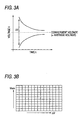
- Fig. 3A is an explanatory view of the timer selection map based on a voltage difference;
- Fig. 3B is an explanatory view of the timer selection map based on the maximum terminal voltage and the voltage difference;
- Fig. 4 is an explanatory view showing the expanded function of the voltage equalization control system.
- the voltage equalization control system 1 shown in Fig. 1 is mainly applied to a power source of low voltage mechanism (for example, 12V battery of a vehicle) and intended to an assembled battery 2 which is used as the power source of low voltage mechanism with the comparatively small number of accumulators CL, ... connected in series.
- an accumulator CL is assumed to be, for example, a rechargeable lithium-ion battery or an electric double layer capacitor.
- a single cell of the above, a plurality of the series connected cells, a plurality of the parallel connected cells, and their combination are to be represented as the accumulator CL.
- the voltage equalization control system 1 is provided with a voltage balanced circuit (voltage equalization unit) 3 which equalizes the terminal voltages in a plurality of accumulators CL, ... through energy transfer between the accumulators CL, ..., a maximum/minimum voltage detector (voltage detector) 4 which detects the maximum terminal voltage and the minimum terminal voltage of the cell voltages after detecting the terminal voltage (cell voltage) in every accumulator CL and comparing with each other, a voltage difference calculator 5 which calculates a voltage difference between the maximum terminal voltage and the minimum terminal voltage detected by the maximum/minimum voltage detector 4, a timer setting unit (operational time setting unit) 6 which sets an operational time of the timer according to the voltage difference calculated by the voltage difference calculator 5, and an operational time controller 7 which presets the operational time set by the timer setting unit 6 in the timer and operates the voltage balanced circuit 3 at the set time.
- a voltage balanced circuit voltage equalization unit 3 which equalizes the terminal voltages in a plurality of accumulators CL, ... through energy transfer
- each functional unit (the maximum/minimum voltage detector 4, the voltage difference calculator 5, the timer setting unit 6, and the operational time controller 7) for controlling the voltage balanced circuit 3 is formed by the firmware of a microcomputer including amplifiers and peripheral circuits which detect the voltages of the respective accumulators CL.
- the voltage balanced circuit 3 a circuit using a transformer or a circuit using the power source IC being insulated can be used.
- the whole voltage equalization control system 1 can be formed as the firmware also including the function of the voltage balanced circuit 3.
- Fig. 2 shows an example of the voltage balanced circuit 3 using a transformer, which equalizes the cell voltages through charging and discharging by using a dielectric voltage of the transformer 10 having an iron core.
- the transformer 10 has a plurality of basic windings 10 m, ... provided correspondingly to the respective accumulators CL, ..., and each of the basic windings 10 m includes a first winding 10 ma and a second winding 10 mb which are divided from a center tap 10 mt. It is designed in that the number of windings is identical in the respective basic windings 10 m, ... and that the number of the first windings 10 ma is equal to the number of the second windings 10 mb.
- the center tap 10 mt works as a winding start terminal of the first winding 10 ma and a winding end terminal of the second winding 10 mb and it is connected to a negative electrode of the corresponding accumulator CL.
- a switching element SW and a first diode Dl are connected between the winding end terminal of the first winding 10 ma and the positive electrode of the corresponding accumulator CL, and the winding start terminal of the second winding 10 mb is connected to the positive electrode of the corresponding accumulator CL through a second diode D2.
- the switching element SW uses a semiconductor switch such as FET, and it is turned on/off according to a pulse control signal supplied from a controller 11.
- the controller 11 includes a pulse oscillator and makes this pulse oscillator oscillate, for example, in some KHz frequencies, to create a pulse control signal, and controls the switching elements SW, ... on/off in synchronization.
- the accumulated current according to the energy accumulation into the transformer 10 flows from the accumulator CL of the maximum terminal voltage Vmax to the basic winding 10 m, while when the respective switching elements SW are turned off, the discharge current according to the energy discharge from the transformer 10 flows from the basic winding 10 m to the accumulator CL of the minimum terminal voltage Vmin, and as a result, the voltage equalizing operation is performed among the cells at the both points of accumulating energy into the transformer 10 and discharging energy from the transformer 10.
- the above voltage balanced circuit 3 is controlled to operate within the operational time set based on the voltage difference between the maximum terminal voltage and the minimum terminal voltage. Namely, when any different power source for operating the voltage balanced circuit 3 cannot be provided, the assembled battery 2 itself has to supply the power, and since the transfer of energy between the accumulators CL in the voltage equalization is accompanied by loss, when the voltage balanced circuit 3 is operated for a long time, the consumption energy of the whole assembled battery 2 reaches a non-negligible level and the remaining energy is decreased on the whole.
- the assembled battery 2 when the assembled battery 2 is formed by the capacitors as the accumulators CL and it is applied to a battery of vehicle, because of the characteristic of the capacitor, it can discharge a larger electricity temporarily according as it keeps a higher voltage with the larger the remaining energy, and it can get a favorable starting operation.
- the capacitor however, has a smaller capacitance than the general secondary battery, and therefore, when it performs the voltage equalizing operation through a long time operation by the voltage balanced circuit 3, the remaining energy of the capacitor is decreased, the terminal voltage is deteriorated, and there is a fear that a favorable starting operation cannot be obtained.
- the voltage equalizing operation is performed by the voltage balanced circuit 3 for the time set depending on the voltage difference between the maximum terminal voltage and the minimum terminal voltage of the cell voltages in every accumulator CL, hence to prevent from unnecessary energy loss owing to the voltage equalizing operation by the voltage balanced circuit 3.
- the maximum/minimum voltage detector 4 includes an amplifier for detecting a terminal voltage in every accumulator CL, and the output voltages of the respective amplifiers are compared with each other by using a multi-staged comparator, hence to detect the maximum terminal voltage Vmax and the minimum terminal voltage Vmin.
- the voltage difference ⁇ V between the maximum terminal voltage Vmax and the minimum terminal voltage Vmin detected is calculated by the voltage difference calculator 5 and sent to the timer setting unit 6.
- the timer setting unit 6 sets the preset value of the timer (count down timer in this embodiment) which sets the time for voltage equalizing operation of the voltage balanced circuit 3, with the voltage difference ⁇ V as parameter, referring to the timer selection map previously stored.
- the voltage equalizing operation of the assembled battery 2 in the voltage balanced circuit 3 becomes a convergent operation into the average voltage obtained by averaging the total sum of the terminal voltages in the respective accumulators CL, and the time required for equalizing the terminal voltages between the accumulators CL needs complicated calculation, depending on the characteristic of the accumulator CL, the number of the accumulators CL forming the assembled battery 2, the control method of the voltage balanced circuit 3, and the voltage equalizing ability.
- the energy shift amount of voltage equalization is the maximum, it takes the longest time for the voltage equalization.
- the energy shift amount for voltage equalization gets greater according as the voltage difference becomes larger between the accumulators CL, ..., and at a place where there is no voltage difference, the energy shift amount for equalization gets greater according as the terminal voltage of the accumulator CL becomes higher.
- the energy shift amount for equalization becomes maximum in a pattern of getting in halves the number of the cells having the maximum terminal voltage and the number of the cells having the minimum terminal voltage within this normal voltage range, when it takes the longest time to converge to the convergent voltage between the maximum terminal voltage and the minimum terminal voltage (the mean voltage between the maximum terminal voltage and the minimum terminal voltage), as illustrated in Fig. 3A.
- a timer selection map characterized as shown in Fig. 3A is created in a pattern where a half of the cells have the upper limited voltage as the maximum terminal voltage and another half of the cells having the lower limited voltage as the minimum terminal voltage.
- the time required for equalization through convergence of the voltage of each cell within the set range is previously obtained through simulation or experiment with the voltage difference ⁇ V used as a parameter and stored as the preset value of the timer, considering the characteristic of the accumulator CL, the number of the accumulators CL forming the assembled battery 2, the control method of the voltage balanced circuit 3, and the voltage equalization ability.
- the timer selection map with the upper limited voltage of the accumulator as reference, when the terminal voltage of the accumulator CL is the highest in the normal range, the voltage difference ⁇ V is used as the parameter, to determine the operation time of the voltage balanced circuit 3, and when the actual maximum terminal voltage Vmax of the accumulator CL is lower than the upper limited voltage, since the time required for equalization becomes shorter than the operation time determined according to the map, this can be uniformly applied to various situations where the actual maximum terminal voltage Vmax varies.
- the map has a comparatively simple structure, equalization can be performed with practically adequate accuracy and it can restrain the unnecessary energy loss by avoiding the long time operation for voltage equalization.
- a timer selection map with the maximum terminal voltage Vmax and the voltage difference ⁇ V as the parameters is created and this timer selection map may be used.
- the timer selection map based on the maximum terminal voltage Vmax and the voltage difference ⁇ V the relationship between the voltage difference ⁇ V and the operational time becomes the same feature as shown in Fig. 3A in a place where the maximum terminal voltage Vmax in the map corresponds to the upper limited voltage, and the larger the voltage difference ⁇ V becomes, the longer it takes for voltage equalization.
- the higher the maximum terminal voltage Vmax in the map becomes the longer it takes for voltage equalization.
- the time set by using the above timer selection map is preset in the timer by the operational time controller 7.
- the operational time controller 7 supplies a control signal for supplying an oscillation pulse to the controller 11 of the voltage balanced circuit 3, to start the voltage equalizing operation, and makes the timer operate to start the countdown at a predetermined timing when the assembled battery 2 is in a rest state, for example, when the assembled battery 2 is used for the power source of a hybrid car or an electric vehicle, at a timing after a vehicle stops at a key switch off.
- the operating time of the voltage balanced circuit 3 is properly modified through feedback of cell voltage by the voltage balanced circuit 3. Namely, when the timer starts and the equalizing operation of each cell by the voltage balanced circuit 3 starts, the maximum/minimum voltage detector 4 monitors the voltage of each cell as needed and the voltage difference ⁇ V between the maximum terminal voltage Vmax and the minimum terminal voltage Vmin calculated by the voltage difference calculator 5 is properly updated. Every time this voltage difference ⁇ V is updated, the timer setting unit 6 resets the preset value of the timer by using the timer selection map and supplies it to the operational time controller 7.
- the operational time controller 7 supplies a stopping signal to the voltage balanced circuit 3, hence to stop the voltage equalizing operation.
- the voltage equalizing operation by the voltage balanced circuit 3 is stopped by a control signal of stopping the pulse oscillation supplied from the operational time controller 7 to the controller 11, or by the shutoff of the power source for the voltage balanced circuit 3.
- Fig. 4 shows the structure of a voltage equalization control system 1A with the convergence voltage and the longest time limited, which comprises a voltage balance target setting unit 8 and a voltage comparator 9 in addition to the units of the voltage equalization control system 1, that is, the voltage balanced circuit 3, the maximum/minimum voltage detector 4, the voltage difference calculator 5, the timer setting unit 6, and the operational time controller 7.
- the voltage balance target setting unit 8 is to set the target value (voltage width) of the convergence voltage in equalizing the voltage of the respective accumulators CL, ... through temporal operation of the voltage balanced circuit 3 according to the timer, the voltage comparator 9 compares the voltage difference ⁇ V with the target value, and depending on the comparison result, the voltage balanced circuit 3 is turned off according to the temporal operation or forced outage of the timer.
- the voltage equalization control system 1A can turn on the voltage balanced circuit 3 so to do the equalization operation according to an external operation ON signal input to the operational time controller 7.
- the voltage balanced circuit 3 when a condition that the voltage difference ⁇ V is the target value and less is satisfied, when the timer is before start, the voltage balanced circuit 3 is turned off and not operated, and when the timer starts countdown and the voltage balanced circuit 3 is operated, the voltage balanced circuit 3 is forcedly turned off even when the timer is counting down. In this case, even when the voltage balanced circuit 3 is operated, when the voltage difference ⁇ V does not converge to the target value previously set and the less, the longest operating time of the voltage balanced circuit 3 is controlled according to the temporal operation depending on the voltage difference ⁇ V by the timer.
- the accumulator CL is judged to be degraded and the voltage balanced circuit 3 is forcedlyturned off and locked. In this case, even when an external operation ON signal is entered, the voltage balanced circuit 3 never operates and it is locked in the off-state, thereby securing the safety.
- the operational time controller 7 may control the switching frequency of the switching element SW in the equalizing operation of the voltage balanced circuit 3 to vary depending on the voltage difference ⁇ V. Specifically, when the voltage difference AV is large, the switching frequency is set low, hence to make the ON time of the switching element SW longer, thereby enhancing the equalization processing ability, while when the voltage difference ⁇ V is small, the switching frequency is set high, hence to make the ON time of each switching element SW shorter and to decrease the accumulated energy and the discharge energy into and from the transformer 10, thereby decreasing the useless loss.
- the voltage equalization can be performed by the voltage balanced circuit 3 at the optimum timing depending on the state of the individual accumulators CL forming the assembled battery 2, the long time voltage equalizing operation can be avoided and a decrease in the remaining energy can be moderated, hence to maintain the quality of battery.
- the assembled battery When it does not converge to the target value within the set time of the timer, the assembled battery can be judged to be defective or degraded and the quality of the battery can be maintained in the optimum state.
- Figs. 5 and 6 are concerned about a second embodiment of the invention: Fig. 5 is a structural view of the voltage equalization control system and Fig. 6 is a circuit diagram of the voltage balanced circuit.
- the second embodiment is applied to the case where a plurality of accumulators CL, ... are connected in series a lot, hence to form a power source of high voltage mechanism, like a battery for a hybrid car or an electric vehicle.
- the voltage equalization control system 100 of the second embodiment is designed to simplify the processing, by putting together into the microcomputer 50 the functions of the voltage difference calculator (voltage difference calculating means) 5 and the timer setting unit (operational time setting means) 6 in the voltage equalization control system 1 of the first embodiment.
- the voltage equalization control system 100 further comprises each voltage equalization controller 23 in every battery module 20a, which controller includes the voltage balanced circuit (module voltage equalizing means) 21 and the operational time controller (operational time controlling means) 22, and the microcomputer 50 intensively controls the voltage equalization controllers 23 in the respective battery modules 20a.
- the voltage balanced circuit 21 has a function of equalizing the voltages in the accumulators CL, ... within each battery module 20a as well as a function of detecting the maximum terminal voltage Vmax and the minimum terminal voltage Vmin of the accumulators CL, ....
- Fig. 6 shows a circuit example of the voltage balanced circuit 21, which is designed to have a maximum voltage detector 12 for detecting the maximum terminal voltage Vmax of the accumulators CL, ... and a minimum voltage detector 13 for detecting the minimum terminal voltage Vmin in addition to the structure of the voltage balanced circuit 3 of the first embodiment.
- the maximum terminal voltage Vmax detected by the maximum voltage detector 12 and the minimum terminal voltage Vmin detected by the minimum voltage detector 13 are supplied to the microcomputer 50, where the voltage difference ⁇ V is calculated.
- the maximum voltage detector 12 has two input ports; one input port is connected to a condenser C1 connected to the first winding 10 ma of some basic winding 10 m, and the other input port is connected to the center tap 10 mt of the basic winding 10 m.
- the condenser C1 is a condenser for storing (recording) voltage occurring in the first winding 10 ma of the basic winding 10 m at a point of turning on the switching element SW, which is connected between the output side of a diode D3 connected to the winding end terminal of the first winding 10 ma of some basic winding 10 m and the center tap 10 mt of the basic winding 10 m.
- the minimum voltage detector 13 has two input ports; one input port is connected to a condenser C2 connected to the second winding 10 mb of some basic winding 10 m, and the other input port is connected to the center tap 10 mt of the basic winding 10 m.
- the condenser C2 is a condenser for storing (recording) voltage occurring in the second winding 10 mb of the basic winding 10 m at a point of turning off the switching element SW, which is connected between the output side of a diode D4 connected to the winding start terminal of the second winding 10 mb of some basic winding 10 m and the center tap 10 mt of the basic winding 10 m.
- the voltage equalizing operation is started by a control signal for making the controller 11 of the voltage balanced circuit 21 to supply an oscillation pulse.
- the microcomputer 50 calculates the voltage difference ⁇ V at once according to the data, and according to the resultant voltage difference ⁇ V, the temporal control for the voltage equalizing operation is performed on each of the voltage balanced circuits 21.
- the controlling form of the temporal control according to the second embodiment is the form of controlling the temporal operation of all the voltage balanced circuits 21 according to the voltage difference ⁇ Vbetween the maximum terminal voltage Vmax and the minimum voltage Vmin of the accumulators CL, ... within the assembled battery 20.
- the time of the temporal operation on all the voltage balanced circuits 21 is uniformly set referring to the same timer selection map as the first embodiment.
- the timer selection map a single map applied to the whole assembled battery 20 is used.
- the voltage difference ⁇ V is properly updated through voltage feedback and the preset value of the timer is reset.
- the voltage equalizing operations by all the voltage balanced circuits 21 are stopped by supplying the control signals for stopping the pulse oscillation to the controllers 11 of the voltage balanced circuits 21 or by shutting down the power of the circuit.
- the operational time is set according to the voltage difference between the maximum voltage and the minimum voltage of, for example, the representative voltage of the respective battery modules 20a, and within this operational time, the timer control for the voltage equalizing operation is performed on all the voltage balanced circuits 21 within the assembled battery 20.
- the timer selection map in the first temporal control can be used.
Landscapes
- Engineering & Computer Science (AREA)
- Power Engineering (AREA)
- Charge And Discharge Circuits For Batteries Or The Like (AREA)
- Electric Propulsion And Braking For Vehicles (AREA)
- Secondary Cells (AREA)
Applications Claiming Priority (1)
| Application Number | Priority Date | Filing Date | Title |
|---|---|---|---|
| JP2004355299A JP2006166615A (ja) | 2004-12-08 | 2004-12-08 | 蓄電デバイスの電圧均等化制御システム |
Publications (2)
| Publication Number | Publication Date |
|---|---|
| EP1670113A2 true EP1670113A2 (fr) | 2006-06-14 |
| EP1670113A3 EP1670113A3 (fr) | 2006-10-11 |
Family
ID=35999586
Family Applications (1)
| Application Number | Title | Priority Date | Filing Date |
|---|---|---|---|
| EP05026901A Withdrawn EP1670113A3 (fr) | 2004-12-08 | 2005-12-08 | Système de contrôle d'égalisation de tension pour un accumulateur |
Country Status (3)
| Country | Link |
|---|---|
| US (1) | US20060119319A1 (fr) |
| EP (1) | EP1670113A3 (fr) |
| JP (1) | JP2006166615A (fr) |
Cited By (8)
| Publication number | Priority date | Publication date | Assignee | Title |
|---|---|---|---|---|
| EP2083494A1 (fr) * | 2006-11-02 | 2009-07-29 | Panasonic Corporation | Dispositif de détection d'anomalie pour élément de mémorisation, procédé de détection d'anomalie pour élément de mémorisation, programme de détection d'anomalie pour élément de mémorisation, et support d'enregistrement pouvant |
| WO2010079061A1 (fr) * | 2009-01-07 | 2010-07-15 | Robert Bosch Gmbh | Equilibrage de cellules de batterie |
| EP2216874A1 (fr) | 2009-02-04 | 2010-08-11 | Samsung SDI Co., Ltd. | Bloc batterie et procédé d'équilibrage des cellules de batterie |
| CN102110862A (zh) * | 2009-12-28 | 2011-06-29 | 三星Sdi株式会社 | 电池组及其线路断开检测方法 |
| DE102010002326A1 (de) * | 2010-02-25 | 2011-08-25 | SB LiMotive Company Ltd., Kyonggi | Verfahren zum Ausbalancieren von Ladezuständen einer Batterie mit mehreren Batteriezellen sowie ein entsprechendes Batteriemanagementsystem und eine Batterie |
| EP2448085A1 (fr) * | 2010-11-01 | 2012-05-02 | The Boeing Company | Convertisseur d'équilibrage de la tension d'une cellule |
| EP2685591A1 (fr) * | 2012-07-10 | 2014-01-15 | Mitsubishi Jidosha Kogyo Kabushiki Kaisha | Unité de gestion de batterie pour véhicule |
| CN106611984A (zh) * | 2016-03-15 | 2017-05-03 | 西安华泰半导体科技有限公司 | 一种电池管理方法及系统 |
Families Citing this family (30)
| Publication number | Priority date | Publication date | Assignee | Title |
|---|---|---|---|---|
| JP3795499B2 (ja) * | 2003-12-26 | 2006-07-12 | 富士重工業株式会社 | 蓄電素子の電圧均等化装置 |
| JP4590379B2 (ja) * | 2006-08-01 | 2010-12-01 | Fdk株式会社 | 多直列蓄電セルを充放電させるシステム |
| JP5008950B2 (ja) * | 2006-11-08 | 2012-08-22 | パナソニック株式会社 | 充電システム、電池パック、及びその充電方法 |
| JP5517398B2 (ja) * | 2007-03-15 | 2014-06-11 | 三菱重工業株式会社 | 蓄電システム |
| WO2008139103A2 (fr) * | 2007-04-18 | 2008-11-20 | Valeo Equipements Electriques Moteur | Dispositif de stockage d'energie, notamment pour vehicule automobile |
| FR2927200B1 (fr) * | 2008-02-06 | 2013-03-29 | Valeo Equip Electr Moteur | Dispositif de stockage d'energie, notamment pour vehicule automobile |
| JP5386872B2 (ja) * | 2008-07-29 | 2014-01-15 | 株式会社デンソー | 組電池監視制御装置 |
| CN101877489B (zh) * | 2009-04-30 | 2012-11-21 | 富港电子(昆山)有限公司 | 电池充电电路 |
| KR101182336B1 (ko) | 2009-09-14 | 2012-10-09 | 이정용 | 배터리 관리 시스템의 복수의 셀 전압 밸런싱을 위한 제어방법 |
| US8917061B2 (en) * | 2009-09-18 | 2014-12-23 | Schneider Electric It Corporation | System and method for battery cell balancing |
| EP2502323A1 (fr) * | 2009-11-19 | 2012-09-26 | Robert Bosch GmbH | Procédé et dispositif d'équilibrage des tensions électriques dans des éléments d'accumulateur électrique |
| JP5338701B2 (ja) | 2010-02-12 | 2013-11-13 | 株式会社デンソー | 電池監視装置 |
| JP5736694B2 (ja) * | 2010-09-03 | 2015-06-17 | ソニー株式会社 | 制御装置及び方法、並びに電源装置 |
| JP5567956B2 (ja) * | 2010-09-16 | 2014-08-06 | 矢崎総業株式会社 | 複数組電池のセル電圧均等化装置 |
| DE102010063971A1 (de) * | 2010-12-22 | 2012-06-28 | Bayerische Motoren Werke Aktiengesellschaft | Verfahren und Vorrichtung zum Betreiben eines Energiespeichers |
| CN102148522B (zh) * | 2011-05-04 | 2013-05-01 | 柳州五菱汽车有限责任公司 | 一种蓄电池组控制方法及系统 |
| US8793042B2 (en) | 2011-07-28 | 2014-07-29 | Ford Global Technologies, Llc | Method and system for charging a vehicle battery |
| US9139103B2 (en) | 2011-07-28 | 2015-09-22 | Ford Global Technologies, Llc | Battery cell capacity balancing system and method |
| US9145064B2 (en) | 2011-07-28 | 2015-09-29 | Ford Global Technologies, Llc | Battery cell capacity balancing system and method |
| US8676419B2 (en) | 2011-07-28 | 2014-03-18 | Ford Global Technologies, Llc | Time-based vehicle battery balancing system and method |
| US8897940B2 (en) | 2011-07-28 | 2014-11-25 | Ford Global Technologies, Llc | Battery cell voltage balancing system and method |
| CN103001297B (zh) * | 2012-12-31 | 2014-12-10 | 中南大学 | 一种串联电容器组谐振式电压均衡充电方法及其系统 |
| CN105027383B (zh) * | 2013-01-25 | 2018-04-17 | 日立汽车系统株式会社 | 单体电池控制器和电池监视装置 |
| KR101592200B1 (ko) * | 2013-08-28 | 2016-02-05 | 주식회사 엘지화학 | 랙을 포함하는 전지팩의 랙 전압 밸런싱 방법 |
| DE102015112524A1 (de) * | 2015-07-30 | 2017-02-02 | Halla Visteon Climate Control Corporation | Verfahren zur Spannungsbalancierung von in Reihe geschalteten Kondensatoren |
| TWI558064B (zh) * | 2015-07-31 | 2016-11-11 | 宏碁股份有限公司 | 電池平衡裝置及其電池平衡方法 |
| KR102025286B1 (ko) | 2016-07-12 | 2019-09-26 | 주식회사 엘지화학 | 배터리 셀 밸런싱의 방법 및 시스템 |
| CN209488195U (zh) * | 2016-10-12 | 2019-10-11 | Oppo广东移动通信有限公司 | 移动终端 |
| US11239670B2 (en) * | 2018-09-16 | 2022-02-01 | Richard Landry Gray | Cell balancing battery module and electrical apparatus |
| CN110931895B (zh) * | 2019-11-27 | 2023-05-30 | 深圳市科陆电子科技股份有限公司 | Bms电池均衡维护方法 |
Citations (7)
| Publication number | Priority date | Publication date | Assignee | Title |
|---|---|---|---|---|
| US5644212A (en) * | 1994-11-11 | 1997-07-01 | Fuji Jukogyo Kabushiki Kaisha | Traction battery management system |
| US5994873A (en) * | 1996-12-26 | 1999-11-30 | Toshiba Battery Co., Ltd. | Correction device and correction method for secondary batteries connected in series |
| US5998969A (en) * | 1997-05-12 | 1999-12-07 | Nissan Motor Co., Ltd. | Apparatus for regulating state of charge of cells of battery set |
| JP2002223528A (ja) * | 2000-11-21 | 2002-08-09 | Nagano Japan Radio Co | 蓄電素子の電圧均等化装置 |
| EP1278287A1 (fr) * | 2001-07-19 | 2003-01-22 | Nisshinbo Industries, Inc. | Unité de condensateurs comprenant des condensateurs à double couche électrique, procédé de contrôle et appareil de contrôle correspondant, et accumulateur pour un véhicule automobile |
| US20030062874A1 (en) * | 2001-09-28 | 2003-04-03 | Sanyo Electric Co., Ltd. | Circuit for adjusting charging rate of cells in combination |
| US6624612B1 (en) * | 2001-10-30 | 2003-09-23 | Symbol Technologies, Inc. | System and method to facilitate voltage balancing in a multi-cell battery |
Family Cites Families (13)
| Publication number | Priority date | Publication date | Assignee | Title |
|---|---|---|---|---|
| US3514687A (en) * | 1966-12-08 | 1970-05-26 | North Electric Co | Emergency end cell battery charger |
| US4670700A (en) * | 1985-02-13 | 1987-06-02 | Exciter Battery & Electric Company, Inc. | Battery chargers for secondary cells, and or batteries |
| US4816736A (en) * | 1987-03-12 | 1989-03-28 | Globe-Union Inc. | Polyphase alternator and dual voltage battery charging system for multiple voltage loads |
| US4908526A (en) * | 1988-06-03 | 1990-03-13 | Harris Corporation | Pulse generator output voltage calibration circuit |
| US5479083A (en) * | 1993-06-21 | 1995-12-26 | Ast Research, Inc. | Non-dissipative battery charger equalizer |
| US5656915A (en) * | 1995-08-28 | 1997-08-12 | Eaves; Stephen S. | Multicell battery pack bilateral power distribution unit with individual cell monitoring and control |
| US5710504A (en) * | 1996-05-20 | 1998-01-20 | The Board Of Trustees Of The University Of Illinois | Switched capacitor system for automatic battery equalization |
| JP3099181B2 (ja) * | 1996-09-10 | 2000-10-16 | 本田技研工業株式会社 | 蓄電器の電圧制御装置 |
| US5869950A (en) * | 1997-10-30 | 1999-02-09 | Lockheed Martin Corp. | Method for equalizing the voltage of traction battery modules of a hybrid electric vehicle |
| US6078165A (en) * | 1998-12-18 | 2000-06-20 | Chrysler Corporation | Multiplexed modular battery management system for large battery packs |
| US6642693B2 (en) * | 2000-11-21 | 2003-11-04 | Nagano Japan Radio Co., Ltd. | Voltage equalizing apparatus for battery devices |
| JP3813587B2 (ja) * | 2003-01-30 | 2006-08-23 | 東芝エルエスアイシステムサポート株式会社 | モータ制御回路、半導体集積回路、指示装置及びモータ制御方法 |
| JP4186916B2 (ja) * | 2004-11-18 | 2008-11-26 | 株式会社デンソー | 組電池管理装置 |
-
2004
- 2004-12-08 JP JP2004355299A patent/JP2006166615A/ja active Pending
-
2005
- 2005-12-08 EP EP05026901A patent/EP1670113A3/fr not_active Withdrawn
- 2005-12-08 US US11/297,193 patent/US20060119319A1/en not_active Abandoned
Patent Citations (7)
| Publication number | Priority date | Publication date | Assignee | Title |
|---|---|---|---|---|
| US5644212A (en) * | 1994-11-11 | 1997-07-01 | Fuji Jukogyo Kabushiki Kaisha | Traction battery management system |
| US5994873A (en) * | 1996-12-26 | 1999-11-30 | Toshiba Battery Co., Ltd. | Correction device and correction method for secondary batteries connected in series |
| US5998969A (en) * | 1997-05-12 | 1999-12-07 | Nissan Motor Co., Ltd. | Apparatus for regulating state of charge of cells of battery set |
| JP2002223528A (ja) * | 2000-11-21 | 2002-08-09 | Nagano Japan Radio Co | 蓄電素子の電圧均等化装置 |
| EP1278287A1 (fr) * | 2001-07-19 | 2003-01-22 | Nisshinbo Industries, Inc. | Unité de condensateurs comprenant des condensateurs à double couche électrique, procédé de contrôle et appareil de contrôle correspondant, et accumulateur pour un véhicule automobile |
| US20030062874A1 (en) * | 2001-09-28 | 2003-04-03 | Sanyo Electric Co., Ltd. | Circuit for adjusting charging rate of cells in combination |
| US6624612B1 (en) * | 2001-10-30 | 2003-09-23 | Symbol Technologies, Inc. | System and method to facilitate voltage balancing in a multi-cell battery |
Non-Patent Citations (1)
| Title |
|---|
| PATENT ABSTRACTS OF JAPAN vol. 2002, no. 12, 12 December 2002 (2002-12-12) -& JP 2002 223528 A (NAGANO JAPAN RADIO CO; FUJI HEAVY IND LTD), 9 August 2002 (2002-08-09) * |
Cited By (14)
| Publication number | Priority date | Publication date | Assignee | Title |
|---|---|---|---|---|
| US8085051B2 (en) | 2006-11-02 | 2011-12-27 | Panasonic Corporation | Abnormality detecting device for storage element, abnormality detecting method for storage element, abnormality detecting program for storage element, and computer-readable recording medium storing abnormality detecting program |
| EP2083494A4 (fr) * | 2006-11-02 | 2010-02-10 | Panasonic Corp | Dispositif de détection d'anomalie pour élément de mémorisation, procédé de détection d'anomalie pour élément de mémorisation, programme de détection d'anomalie pour élément de mémorisation, et support d'enregistrement pouvant |
| EP2083494A1 (fr) * | 2006-11-02 | 2009-07-29 | Panasonic Corporation | Dispositif de détection d'anomalie pour élément de mémorisation, procédé de détection d'anomalie pour élément de mémorisation, programme de détection d'anomalie pour élément de mémorisation, et support d'enregistrement pouvant |
| WO2010079061A1 (fr) * | 2009-01-07 | 2010-07-15 | Robert Bosch Gmbh | Equilibrage de cellules de batterie |
| EP2216874A1 (fr) | 2009-02-04 | 2010-08-11 | Samsung SDI Co., Ltd. | Bloc batterie et procédé d'équilibrage des cellules de batterie |
| US8350528B2 (en) | 2009-02-04 | 2013-01-08 | Samsung Sdi Co., Ltd. | Battery pack and balancing method of battery cells |
| CN102110862A (zh) * | 2009-12-28 | 2011-06-29 | 三星Sdi株式会社 | 电池组及其线路断开检测方法 |
| CN102110862B (zh) * | 2009-12-28 | 2014-07-16 | 三星Sdi株式会社 | 电池组及其线路断开检测方法 |
| DE102010002326A1 (de) * | 2010-02-25 | 2011-08-25 | SB LiMotive Company Ltd., Kyonggi | Verfahren zum Ausbalancieren von Ladezuständen einer Batterie mit mehreren Batteriezellen sowie ein entsprechendes Batteriemanagementsystem und eine Batterie |
| US9252464B2 (en) | 2010-02-25 | 2016-02-02 | Robert Bosch Gmbh | Method for balancing states of charge of a battery having a plurality of battery cells as well as a corresponding battery management system and a battery |
| EP2448085A1 (fr) * | 2010-11-01 | 2012-05-02 | The Boeing Company | Convertisseur d'équilibrage de la tension d'une cellule |
| US8773071B2 (en) | 2010-11-01 | 2014-07-08 | The Boeing Company | System and method for cell voltage balancing |
| EP2685591A1 (fr) * | 2012-07-10 | 2014-01-15 | Mitsubishi Jidosha Kogyo Kabushiki Kaisha | Unité de gestion de batterie pour véhicule |
| CN106611984A (zh) * | 2016-03-15 | 2017-05-03 | 西安华泰半导体科技有限公司 | 一种电池管理方法及系统 |
Also Published As
| Publication number | Publication date |
|---|---|
| US20060119319A1 (en) | 2006-06-08 |
| JP2006166615A (ja) | 2006-06-22 |
| EP1670113A3 (fr) | 2006-10-11 |
Similar Documents
| Publication | Publication Date | Title |
|---|---|---|
| EP1670113A2 (fr) | Système de contrôle d'égalisation de tension pour un accumulateur | |
| US10141551B2 (en) | Battery system | |
| US7085661B2 (en) | State detecting system and device employing the same | |
| CN108292854B (zh) | 电池控制装置 | |
| EP2400626B1 (fr) | Circuit de contrôle de batterie | |
| US8704488B2 (en) | Battery pack and method of controlling the same | |
| US11011920B2 (en) | Energy storage apparatus for engine start-up, method for controlling the same, and vehicle | |
| EP2367261A2 (fr) | Appareil de source d'alimentation à courant continu | |
| US9634498B2 (en) | Electrical storage system and equalizing method | |
| US7609034B2 (en) | Battery pack, method of manufacturing battery pack, and method of controlling battery pack | |
| US20100057385A1 (en) | Accumulator failure detecting device, accumulator failure detecting method, accumulator failure detecting program, and computer-readable recording medium containing the accumulator failure detecting program | |
| US20120293129A1 (en) | Active Battery Cell Balancing Methods with Variable Duration Discharge | |
| JPWO2012143996A1 (ja) | 蓄電装置 | |
| JPWO2018199311A1 (ja) | 管理装置、蓄電装置および蓄電システム | |
| US20120299545A1 (en) | Rechargeable battery power supply starter and cell balancing apparatus | |
| JP2001218376A (ja) | 組電池を構成する単電池の充電状態を制御する装置、方法、該装置を用いた電池モジュールおよび電動車両 | |
| US11230205B2 (en) | Vehicular power supply system, and management device | |
| JP2010220413A (ja) | キャパシタモジュールの均等化制御回路及び均等化制御回路を備えた均等化制御装置 | |
| JP5664310B2 (ja) | 直流電源装置 | |
| JP2003009411A (ja) | 組電池の充電率調整回路 | |
| JP4220953B2 (ja) | セルバランス装置及び方法並びにプログラム | |
| KR20090092890A (ko) | 배터리 시스템의 배터리 균등 충전장치 | |
| JPWO2020022344A1 (ja) | 電源システム、及び管理装置 | |
| JPH11341694A (ja) | 二次電池の充電方法 | |
| JP2000270483A (ja) | 組電池の充電状態制御装置 |
Legal Events
| Date | Code | Title | Description |
|---|---|---|---|
| PUAI | Public reference made under article 153(3) epc to a published international application that has entered the european phase |
Free format text: ORIGINAL CODE: 0009012 |
|
| AK | Designated contracting states |
Kind code of ref document: A2 Designated state(s): AT BE BG CH CY CZ DE DK EE ES FI FR GB GR HU IE IS IT LI LT LU LV MC NL PL PT RO SE SI SK TR |
|
| AX | Request for extension of the european patent |
Extension state: AL BA HR MK YU |
|
| PUAL | Search report despatched |
Free format text: ORIGINAL CODE: 0009013 |
|
| AK | Designated contracting states |
Kind code of ref document: A3 Designated state(s): AT BE BG CH CY CZ DE DK EE ES FI FR GB GR HU IE IS IT LI LT LU LV MC NL PL PT RO SE SI SK TR |
|
| AX | Request for extension of the european patent |
Extension state: AL BA HR MK YU |
|
| RIC1 | Information provided on ipc code assigned before grant |
Ipc: H02J 7/00 20060101ALI20060906BHEP Ipc: G01R 31/36 20060101AFI20060906BHEP |
|
| 17P | Request for examination filed |
Effective date: 20070221 |
|
| AKX | Designation fees paid |
Designated state(s): DE FR |
|
| STAA | Information on the status of an ep patent application or granted ep patent |
Free format text: STATUS: THE APPLICATION HAS BEEN WITHDRAWN |
|
| 18W | Application withdrawn |
Effective date: 20081107 |