EP1669314A1 - Aufzugsanlage mit Informationsdarstellung auf einer Schachttür - Google Patents
Aufzugsanlage mit Informationsdarstellung auf einer Schachttür Download PDFInfo
- Publication number
- EP1669314A1 EP1669314A1 EP05109195A EP05109195A EP1669314A1 EP 1669314 A1 EP1669314 A1 EP 1669314A1 EP 05109195 A EP05109195 A EP 05109195A EP 05109195 A EP05109195 A EP 05109195A EP 1669314 A1 EP1669314 A1 EP 1669314A1
- Authority
- EP
- European Patent Office
- Prior art keywords
- elevator
- shaft
- projector
- image
- door
- Prior art date
- Legal status (The legal status is an assumption and is not a legal conclusion. Google has not performed a legal analysis and makes no representation as to the accuracy of the status listed.)
- Granted
Links
Images


Classifications
-
- B—PERFORMING OPERATIONS; TRANSPORTING
- B66—HOISTING; LIFTING; HAULING
- B66B—ELEVATORS; ESCALATORS OR MOVING WALKWAYS
- B66B3/00—Applications of devices for indicating or signalling operating conditions of elevators
Definitions
- the invention relates to an elevator installation with an elevator car, which is arranged movably in a lift shaft between floors, wherein a landing door for closing the elevator shaft is arranged in at least one floor. Furthermore, the invention relates to a method for displaying information on a shaft door of an elevator installation.
- EP 1 069 065 A1 discloses an elevator installation in which a projector is arranged in an elevator lobby which projects an image onto a shaft door of an elevator installation or onto a cabin door of an elevator cage.
- the object is to provide an elevator installation and a method for displaying information on shaft doors of an elevator installation, in which the display of information is made possible, without affecting the design of the elevator vestibules and still achieve a high-quality representation of the information.
- the invention is based on the idea that in the case of shaft doors, which are made of glass or of a partially transparent material, a projection of an image out of the elevator shaft is possible.
- the image from the projector is projected onto a side of the hoistway door facing the hoistway. Due to the nature of the shaft door, an incident light beam only partially closed reflect a picture is displayed on the other side of the shaft door, which faces an elevator vestibule.
- a material is incorporated into the shaft door, which allows a representation of an image on one side of the shaft door, which is directed to the elevator vestibule.
- a foil which causes partial reflection of the light rays back into the elevator shaft, an image being displayed by this incomplete reflection on the side of the shaft door facing the elevator space .
- This has the advantage that a person waiting in the elevator lobby is not dazzled by the light emitted by the projector.
- the arrangement of a film in the glass shaft doors an improvement of the contrast of the image displayed is possible.
- At least one optical deflection device in the elevator shaft to arrange the projecting light beams projected onto the shaft door.
- the projector of the shaft door is arranged opposite in the elevator shaft. Such an arrangement of the projector requires no further devices for deflecting the light beams.
- the arrangement of the projector is made possible on a shaft door wall or on left- or right-side walls in the elevator shaft. As a result, almost any free space in the elevator shaft can be used to install the projector in a space-saving and inconspicuous manner.
- an image duplication unit is associated with the projector.
- a picture doubling unit By means of such a picture doubling unit, it is possible to generate two identical light beams from one light beam. These two light beams are each fed to a shaft door. It is possible to image the picture on a direct way on two shaft doors.
- a deflection device may also be required in order to supply the two light beams emitted by the image doubling unit to the respective shaft doors and to image the images thereon.
- a deflection device is designed as a mirror.
- a mirror reflects the incoming light rays on the shaft door, whereby by alignment of the mirror, the projection can be aligned exactly on the shaft door.
- the elevator car is attached to an elevator rope and connected via a hanging cable with a control unit.
- the projector and possibly also the deflection devices are positioned at positions in the elevator shaft, which allow a projection of the image on the elevator rope and / or hanging cable over.
- the arrangement of the projector in a corner of the elevator shaft is possible, so that the light rays on the elevator rope and hanging cable run past and impinge on the shaft door.
- sensors are arranged in the elevator shaft, which detect a position of the elevator car and the projection of the image in dependence on the elevator car position can be switched off or switched on. These sensors make it possible to stop the projection in the respective floors in an arriving elevator car. After the elevator car has released the shaft door again, the projection is continued.
- the projector is arranged within the shaft door wall, wherein the image is projected into the elevator shaft into deflecting devices arranged there.
- the deflection devices direct the light beams to the respective landing door.
- the location of the projector in the hoistway door wall allows the projector to be accessible from an elevator vestibule.
- the projector can be maintained or adjusted independently of the operation of the elevator system, for example. This has the advantage that the service providers responsible for the projectors do not have to be made familiar with the circumstances of the elevator control, since otherwise the projectors could only be serviced and operated by the elevator service providers.
- the projector may output a side-by-side or mirror-image.
- a mirror-inverted projection of the image on the elevator shaft directed side of the shaft door is required, so that the image on the opposite side of the shaft door, which faces the elevator lobby, is displayed laterally.
- the image is mirrored at the respective deflection, so that the image must be output from the projector laterally correct.
- the inventive method provides that in a lift shaft, a projector is arranged to output an image and the image is projected onto a side of the shaft door, which is directed to the elevator shaft, the shaft door is partially translucent, so that on the side of the Shaft door, which faces an elevator vestibule, a page-right image is displayed.
- the elevator installation 10 comprises an elevator shaft 11, in which an elevator cage 12 is moved between floors S1, S2, S3 and S4.
- the elevator car 12 is attached to an elevator rope 14 and is moved by a motor (not shown) between the individual floors S1 to S4.
- the elevator car 12 is connected via a suspension cable 21 with a control unit, not shown.
- the elevator shaft 11 is closed by shaft doors 13 in each case.
- the shaft doors 13 In front of the shaft doors 13 there are elevator antechambers 27, 28, 29 and 30 in the respective floors S1 to S4.
- the elevator shaft 11 has a shaft door wall 22 which delimits the elevator shaft 11 from the elevator antechambers 27 to 30.
- the left and right side walls of the elevator shaft 11 are denoted by the reference numerals 23 and 24.
- the shaft doors 13 opposite elevator shaft wall is designated by the reference numeral 25.
- FIG. 1 A first possible arrangement of a projector 15 is shown in the floor S4.
- the projector 15 is arranged opposite the shaft door 13 and projects the image onto the shaft door 13, so that the image is imaged in the elevator lobby 30.
- the projector 15 must output the image mirror-inverted for the correct representation of the image in the elevator lobby 30.
- FIG. 1 An alternative arrangement of a projector is shown in the floor S3.
- the projector 16 is arranged on the shaft door wall 22.
- the projector 16 is assigned a deflecting device 18 in the form of a mirror, which reflects the light beams emitted from above onto the shaft door 13.
- the deflecting device 18 in the form of a mirror, which reflects the light beams emitted from above onto the shaft door 13.
- FIG. 1 Another possibility of the arrangement of a projector 17 is shown in the floors S1 and S2.
- the projector 17 is integrated into the shaft door wall 22 and consequently accessible from the elevator vestibule 27.
- the projector 17 is associated with an image doubling unit 19 which generates two light beams from a light beam which are supplied to the respective mirrors 20 in the floor S1 and the floor S2.
- the mirrors 20 in the floors S1 and S2 reflect the image on the respective shaft door 13 in the floor S1 and S2.
- Such an arrangement has the advantage that only one projector 17 is required to display information on the shaft doors 13 in two floors S1, S2.
- sensors 26 are arranged, which detect the position of the elevator car 12 in the elevator shaft 11.
- the projection of the projector 16 is stopped by a control unit, not shown.
- the projection of projector 16 is continued.
- the projection for each floor S1, S2 can be selectively started or stopped. This means that when the elevator car 12 enters the floor S2, the projection in this floor S2 is interrupted. For example, in the image doubling unit 19, the image doubling provided for the second floor S2 is turned off.
- the projection of the projector 17 for the floor S1 is stopped.
- the projector 15 In order to enable a trouble-free representation of an image on a shaft door 13, it is expedient to arrange the projector 15 in a corner in the elevator shaft 11. This is shown schematically in FIG.
- the projector 15 is the shaft door 13 arranged substantially opposite one another.
- the light beam In order not to disturb the projection of the image by the elevator rope 14 or the hanging cable 21, the light beam is aligned so that it is guided past the elevator cable 14 and the hanging cable 21.
- a trouble-free projection of the image on the shaft door 13 is made possible. This requires image equalization, but this is not a problem with modern projectors or video projectors 15-17.
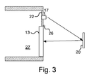
- FIG. 17 An alternative preferred arrangement of a projector is shown in FIG.
- the projector 17 is arranged on the shaft door wall 22.
- the projector 17 is associated with a deflecting device 20 in the form of a mirror 20 which reflects the light rays emitted from above onto the shaft door 13.
- a deflecting device 20 in the form of a mirror 20 which reflects the light rays emitted from above onto the shaft door 13.
- the shaft doors 13 are preferably made of two glass panes, in which a film is included as a rear projection film. Such films typically contain aluminum particles which reflect the incident light beam several times. As a result, a person waiting in the elevator vestibule 27 to 30 is not dazzled by the incident light beam. At the same time an image of an image on the side of the shaft door 13 is thereby made possible, which faces the elevator lobby 27 to 30. Even a frosted glass coating is suitable for the presentation of information on shaft doors 13 according to the invention.
Landscapes
- Indicating And Signalling Devices For Elevators (AREA)
- Elevator Door Apparatuses (AREA)
Abstract
Description
- Die Erfindung betrifft eine Aufzugsanlage mit einer Aufzugskabine, die in einem Aufzugsschacht zwischen Stockwerken bewegbar angeordnet ist, wobei in wenigstens einem Stockwerk eine Schachttür zum Verschliessen des Aufzugsschachts angeordnet ist. Weiter betrifft die Erfindung ein Verfahren zur Darstellung von Informationen auf einer Schachttür einer Aufzugsanlage.
- Um die Wartezeit auf eine Aufzugkabine zu überbrücken, wird den Fahrgästen häufig in der Nähe der Aufzuganlage eine Information in Form von Bildern oder Videos angezeigt. Diese Bilder können sich auf die Bedienung oder den Zustand der Aufzugsanlage beziehen oder aber einfach Werbebotschaften enthalten. Aus der EP 1 069 065 A1 ist eine Aufzugsanlage bekannt, bei der ein Projektor in einem Aufzugsvorraum angeordnet ist, der ein Bild auf eine Schachttür einer Aufzugsanlage oder auf eine Kabinentür einer Aufzugskabine projiziert.
- Aufzüge sind aus modernen Gebäuden nicht mehr wegzudenken. Die modernen Gebäude unterliegen einem aufwändigen architektonischen Design. Die in der EP 1 069 065 A1 vorgeschlagene Lösung erfordert die Anbringung eines Projektors in einem Aufzugsvorraum. Eine derartige Anbringung im Aufzugsvorraum wirkt sich jedoch nachteilig auf das aufwändig gestaltete Design der modernen Bürogebäude aus, da der Projektor von einer Decke abgehängt werden muss und Umlenkvorrichtungen zur Projektion eines Bildes positioniert werden müssen.
- Ausserdem sind die Aufzugsvorräume in modernen Bürogebäuden normalen Lichtverhältnissen ausgesetzt. Unter normalen Tageslichteinflüssen ist für die Projektion eines Bildes auf eine Schachttür mittels eines Videobeamers oder eines Diaprojektors ein sehr hochwertiger Projektor erforderlich. Selbst hochwertige und teure Projektoren können bei normalem Tageslicht kein wirklich qualitativ hochwertiges Bild projizieren.
- Ein weiteres Problem bei der Installation von Projektoren in Aufzugsvorräumen besteht darin, dass der Projektor von der Schachttür weit entfernt angeordnet sein muss, um ein Bild oder Video grossflächig darstellen zu können. Dies führt dazu, dass eine in den Strahlengang des Projektors eintretende Person das darzustellende Bild abdunkelt. Diese Abdunklung kann nur teilweise durch aufwändige Konstruktionen von Umlenkvorrichtungen vermieden werden, wobei diese Konstruktionen die architektonische Gestaltung eines Aufzugsvorraums verunstalten können.
- Vor diesem Hintergrund ergibt sich die Aufgabe, eine Aufzugsanlage und ein Verfahren zur Darstellung von Informationen auf Schachttüren einer Aufzugsanlage anzugeben, bei denen die Darstellung von Informationen ermöglicht wird, ohne das Design der Aufzugsvorräume zu beeinträchtigen und trotzdem eine qualitativ hochwertige Darstellung der Informationen zu erzielen.
- Diese Aufgabe wird durch die Merkmale der unabhängigen Ansprüche gelöst.
- Die Erfindung basiert auf dem Gedanken, dass bei Schachttüren, die aus Glas oder einem teilweise lichtdurchlässigen Material bestehen, eine Projektion eines Bildes aus dem Aufzugsschacht heraus möglich ist. Bei einer derartigen Projektion wird das Bild vom Projektor auf eine Seite der Schachttür, die dem Aufzugsschacht zugewandt ist, projiziert. Durch die Eigenart der Schachttür, einen auftreffenden Lichtstrahl nur teilweise zu reflektieren, wird auf der anderen Seite der Schachttür, die einem Aufzugsvorraum zugewandt ist, ein Bild abgebildet.
- In modernen Bürogebäuden wird sehr häufig Glas oder ein ähnliches Material für Schachttüren eingesetzt, welches wenigstens teilweise lichtdurchlässig ist. Diese Eigenschaft wird bei der erfindungsgemässen Aufzugsanlage vorteilhaft ausgenutzt. Durch die Projektion aus dem Aufzugsschacht heraus ist es nicht mehr erforderlich, einen Projektor und Umlenkvorrichtungen in dem Aufzugsvorraum anzuordnen. In den meisten Aufzugsschächten herrschen abgedunkelte Lichtverhältnisse, so dass eine Projektion aus dem Aufzugsschacht auf eine Schachttür mit einer hohen Qualität erfolgen kann. Ein weiterer Vorteil ergibt sich dadurch, dass niemand in den Strahlengang des Projektors eintreten kann. Somit wird eine Abdunklung der dargestellten Informationen ausgeschlossen.
- Vorteilhafte Ausgestaltungen sind den Unteransprüchen zu entnehmen.
- In einer vorteilhaften Ausgestaltung der Erfindung ist in die Schachttür ein Material eingearbeitet, das eine Darstellung eines Bildes auf einer Seite der Schachttür, die zu dem Aufzugsvorraum gerichtet ist, ermöglicht. Beispielsweise ist es möglich, in die aus Glas bestehenden Schachttüren eine Folie einzuarbeiten, die eine teilweise Reflektion der Lichtstrahlen zurück in den Aufzugsschacht bewirkt, wobei durch diese nicht vollständige Reflektion auf der Seite der Schachttür, die zu dem Aufzugsraum gerichtet ist, ein Bild abgebildet wird. Dies hat den Vorteil, dass eine im Aufzugsvorraum wartende Person nicht durch das vom Projektor ausgestrahlte Licht geblendet wird. Ausserdem ist durch die Anordnung einer Folie in den gläsernen Schachttüren eine Verbesserung des Kontrasts des dargestellten Bilds möglich.
- In einer weiteren vorteilhaften Ausgestaltung der Erfindung ist vorgesehen, wenigstens eine optische Umlenkvorrichtung im Aufzugsschacht anzuordnen, die die vom Projektor ausgehenden Lichtstrahlen auf die Schachttür projiziert. Durch Verwendung derartiger Umlenkvorrichtungen ist es möglich, den Projektor an einer beliebigen Stelle im Aufzugsschacht zu positionieren.
- Bei einer vorteilhaften Ausgestaltung der Erfindung ist der Projektor der Schachttür gegenüberliegend im Aufzugsschacht angeordnet. Eine derartige Anordnung des Projektors erfordert keine weiteren Vorrichtungen zur Umlenkung der Lichtstrahlen.
- Bei Verwendung von den oben erwähnten Umlenkvorrichtungen wird die Anordnung des Projektors an einer Schachttürenwand oder an links- oder rechtsseitigen Wänden im Aufzugsschacht ermöglicht. Dadurch kann fast jeder Freiraum im Aufzugsschacht genutzt werden, um den Projektor platzsparend und unauffällig anzubringen.
- Bei einer weiteren bevorzugten Ausgestaltung der Erfindung ist dem Projektor eine Bildverdopplungseinheit zugeordnet. Mittels einer derartigen Bildverdopplungseinheit ist es möglich, aus einem Lichtstrahl zwei identische Lichtstrahlen zu erzeugen. Diese zwei Lichtstrahlen werden jeweils einer Schachttür zugeführt. Dabei ist es möglich, das Bild auf einem direkten Weg auf zwei Schachttüren abzubilden. Je nach Anordnung des Projektors im Aufzugsschacht kann jedoch auch eine Umlenkvorrichtung erforderlich sein, um die beiden von der Bildverdopplungseinheit abgegebenen Lichtstrahlen den jeweiligen Schachttüren zuzuführen und die Bilder darauf abzubilden.
- In einer besonderen Ausgestaltung der Erfindung ist eine Umlenkvorrichtung als Spiegel ausgebildet. Ein derartiger Spiegel reflektiert die ankommenden Lichtstrahlen auf die Schachttür, wobei durch Ausrichtung des Spiegels die Projektion exakt auf die Schachttür ausgerichtet werden kann.
- In einer weiteren vorteilhaften Ausgestaltung der Erfindung ist die Aufzugskabine an einem Aufzugsseil befestigt und über ein Hängekabel mit einer Steuereinheit verbunden. Um eine störungsfreie Projektion eines Bildes auf der Schachttür zu ermöglichen, sind der Projektor und gegebenenfalls auch die Umlenkvorrichtungen an Positionen im Aufzugsschacht positioniert, die eine Projektion des Bildes am Aufzugsseil und/oder Hängekabel vorbei ermöglichen. Beispielsweise ist die Anordnung des Projektors in einer Ecke des Aufzugsschachts möglich, so dass die Lichtstrahlen am Aufzugsseil und Hängekabel vorbei verlaufen und auf die Schachttür auftreffen.
- Vorteilhaft ist es, wenn in dem Aufzugsschacht Sensoren angeordnet sind, die eine Position der Aufzugskabine erfassen und die Projektion des Bildes in Abhängigkeit von der Aufzugskabinenposition abschaltbar oder einschaltbar ist. Durch diese Sensoren wird es ermöglicht, bei einer ankommenden Aufzugskabine die Projektion in den jeweiligen Stockwerken zu stoppen. Nachdem die Aufzugskabine die Schachttür wieder frei gegeben hat, wird die Projektion fortgesetzt.
- In einer vorteilhaften Ausgestaltung der Erfindung ist der Projektor innerhalb der Schachttürenwand angeordnet, wobei das Bild in den Aufzugsschacht hinein zu dort angeordneten Umlenkvorrichtungen projiziert wird. Die Umlenkvorrichtungen lenken die Lichtstrahlen zu der jeweiligen Schachttür. Die Anordnung des Projektors in der Schachttürenwand ermöglicht es, dass der Projektor von einem Aufzugsvorraum zugänglich ist. Somit kann der Projektor unabhängig von dem Betrieb der Aufzuganlage beispielsweise gewartet oder eingestellt werden. Dies hat den Vorteil, dass die für die Projektoren zuständigen Dienstleister nicht mit den Gegebenheiten der Aufzugssteuerung vertraut gemacht werden müssen, da sonst die Projektoren nur von den Aufzugsdienstleistern gewartet und bedient werden könnten.
- Je nach Anordnung des Projektors im Aufzugsschacht ist es erforderlich, dass der Projektor ein seitenrichtiges oder spiegelverkehrtes Bild ausgibt. So ist bei einer direkten Projektion bei gegenüberliegender Anordnung des Projektors zur Schachttür eine spiegelverkehrte Projektion des Bildes auf die zum Aufzugsschacht gerichtete Seite der Schachttür erforderlich, so dass das Bild auf der gegenüberliegenden Seite der Schachttür, die dem Aufzugsvorraum zugewandt ist, seitenrichtig dargestellt wird. Bei Anordnung des Projektors an der Schachttürenwand oder an den links- und rechtsseitigen Wänden im Aufzugsschacht und der Verwendung einer Umlenkeinrichtung wird das Bild an der jeweiligen Umlenkvorrichtung gespiegelt, so dass das Bild vom Projektor seitenrichtig ausgegeben werden muss.
- Das erfindungsgemässe Verfahren sieht vor, dass in einem Aufzugsschacht ein Projektor zur Ausgabe eines Bildes angeordnet wird und das Bild auf eine Seite der Schachttür, die zu dem Aufzugsschacht gerichtet ist, projiziert wird, wobei die Schachttür teilweise lichtdurchlässig ist, so dass auf der Seite der Schachttür, die einem Aufzugsvorraum zugewandt ist, ein seitenrichtiges Bild dargestellt wird.
- Nachfolgend wird die Erfindung anhand eines Ausführungsbeispiels näher erläutert, das in den Zeichnungen in schematischer Weise dargestellt ist. Es zeigen:
- Fig.1 1
- eine schematische Darstellung eines Aufzugsschachts mit mehreren Projektoren gemäss der vorliegenden Erfindung;
- Fig. 2
- eine Ansicht von oben in den Aufzugsschacht gemäss Fig. 1;
- Fig.3
- eine schematische Darstellung eines Aufzugsschachts mit einem Projektor gemäss einer bevorzugten Ausführungsform der vorliegenden Erfindung.
- Bezug nehmend auf Fig. 1 wird der Aufbau einer erfindungsgemässen Aufzugsanlage 10 erläutert. Die Aufzugsanlage 10 umfasst einen Aufzugsschacht 11, in dem eine Aufzugskabine 12 zwischen Stockwerken S1, S2, S3 und S4 bewegt wird. Die Aufzugskabine 12 ist an einem Aufzugsseil 14 befestigt und wird von einem Motor (nicht dargestellt) zwischen den einzelnen Stockwerken S1 bis S4 bewegt. Die Aufzugskabine 12 ist über ein Hängekabel 21 mit einer nicht dargestellten Steuereinheit verbunden. In den Stockwerken S1 bis S4 wird der Aufzugsschacht 11 jeweils von Schachttüren 13 verschlossen. Vor den Schachttüren 13 befinden sich in den jeweiligen Stockwerken S1 bis S4 Aufzugsvorräume 27, 28, 29 und 30. Der Aufzugsschacht 11 weist eine Schachttürenwand 22 auf, die den Aufzugsschacht 11 von den Aufzugsvorräumen 27 bis 30 abgrenzt. Wie in Fig. 2 dargestellt, sind die links- und rechtsseitigen Wände des Aufzugsschachts 11 mit den Bezugszeichen 23 und 24 bezeichnet. Die den Schachttüren 13 gegenüberliegende Aufzugsschachtwand ist mit dem Bezugszeichen 25 bezeichnet.
- Mehrere alternative Anordnungen von Projektoren 15, 16, 17 in einem Aufzugsschacht 11 sind in Fig. 1 dargestellt. Eine erste mögliche Anordnung eines Projektors 15 ist im Stockwerk S4 dargestellt. Der Projektor 15 ist der Schachttür 13 gegenüberliegend angeordnet und projiziert das Bild auf die Schachttür 13, so dass das Bild im Aufzugsvorraum 30 abgebildet wird. Der Projektor 15 muss zur seitenrichtigen Darstellung des Bildes im Aufzugsvorraum 30 das Bild spiegelverkehrt ausgeben.
- Eine alternative Anordnung eines Projektors wird im Stockwerk S3 gezeigt. Der Projektor 16 ist an der Schachttürenwand 22 angeordnet. Dabei ist dem Projektor 16 eine Umlenkvorrichtung 18 in Form eines Spiegels zugeordnet, der die von oben ausgesendeten Lichtstrahlen auf die Schachttür 13 reflektiert. In der im Stockwerk S3 gezeigten Anordnung des Projektors 16 ist es notwendig, dass das Bild seitenrichtig ausgegeben wird, da der Spiegel 18 eine Spiegelung des Bildes vornimmt.
- Eine weitere Möglichkeit der Anordnung eines Projektors 17 ist in den Stockwerken S1 und S2 dargestellt. Hier ist der Projektor 17 in die Schachttürenwand 22 integriert und demzufolge vom Aufzugsvorraum 27 zugänglich. Dem Projektor 17 ist eine Bildverdopplungseinheit 19 zugeordnet, die aus einem Lichtstrahl zwei Lichtstrahlen generiert, die den jeweiligen Spiegeln 20 im Stockwerk S1 und im Stockwerk S2 zugeführt werden. Die Spiegel 20 in den Stockwerken S1 und S2 reflektieren das Bild auf die jeweilige Schachttür 13 im Stockwerk S1 und S2. Eine derartige Anordnung hat den Vorteil, dass zur Darstellung von Informationen auf den Schachttüren 13 in zwei Stockwerken S1, S2 nur ein Projektor 17 erforderlich ist.
- Im Bereich von Ober- und Unterseiten der Schachttüren 13 sind Sensoren 26 angeordnet, die die Position der Aufzugskabine 12 im Aufzugsschacht 11 erfassen. Wenn die Aufzugskabine 12 in den Bereich des Stockwerks S3 einfährt, das heisst sich nach oben bewegt, wird von einer nicht dargestellten Steuerungseinheit die Projektion des Projektors 16 angehalten. Nachdem die Aufzugskabine 12 die Position im Stockwerk S3 verlassen hat, wird die Projektion von Projektor 16 fortgesetzt. Bei der Nutzung eines Projektors 17 für zwei Stockwerke, wie es in den Stockwerken S1 und S2 dargestellt ist, kann die Projektion für jedes Stockwerk S1, S2 selektiv gestartet oder angehalten werden. Das heisst, dass bei einem Einfahren der Aufzugskabine 12 ins Stockwerk S2 die Projektion in diesem Stockwerk S2 unterbrochen wird. Beispielsweise wird in der Bildverdopplungseinheit 19 die Bildverdopplung, die für das zweite Stockwerk S2 vorgesehen ist, abgeschaltet. Ebenso wird bei einem Einfahren der Aufzugskabine 12 in das Stockwerk S1 die Projektion des Projektors 17 für das Stockwerk S1 gestoppt.
- Um eine störungsfreie Darstellung eines Bildes auf einer Schachttür 13 zu ermöglichen, ist es zweckmässig, den Projektor 15 in einer Ecke im Aufzugsschacht 11 anzuordnen. Dies wird in Fig. 2 schematisch dargestellt. Der Projektor 15 ist der Schachttür 13 im Wesentlichen gegenüberliegend angeordnet. Um die Projektion des Bildes nicht durch das Aufzugsseil 14 oder das Hängekabel 21 zu stören, wird der Lichtstrahl so ausgerichtet, dass er an dem Aufzugsseil 14 und dem Hängekabel 21 vorbeigeleitet wird. Somit wird eine störungsfreie Projektion des Bildes auf der Schachttür 13 ermöglicht. Dies erfordert eine Entzerrung des Bildes, was jedoch mit modernen Projektoren oder Videobeamern 15 bis 17 unproblematisch ist.
- Eine alternative bevorzugte Anordnung eines Projektors wird im Fig. 3 gezeigt. Der Projektor 17 ist an der Schachttürenwand 22 angeordnet. Dabei ist dem Projektor 17 eine Umlenkvorrichtung 20 in Form eines Spiegels 20 zugeordnet, der die von oben ausgesendeten Lichtstrahlen auf die Schachttür 13 reflektiert. Eine derartige Anordnung hat den Vorteil, dass zur Darstellung von Informationen auf den Schachttüren 13 keine komplizierte und teuere Bildverarbeitungseinheit erforderlich ist, da der Lichtstrahl einen optimalen optischen Weg aufweist.
- Die Schachttüren 13 bestehen vorzugsweise aus zwei Glasscheiben, in die eine Folie als Rückprojektionsfolie eingeschlossen ist. Derartige Folien beinhalten typischerweise Aluminiumpartikel, die den auftreffenden Lichtstrahl mehrmals reflektieren. Dadurch wird eine Person, die im Aufzugsvorraum 27 bis 30 wartet, nicht vom auftreffenden Lichtstrahl geblendet. Gleichzeitig wird dadurch eine Abbildung eines Bildes auf der Seite der Schachttür 13 ermöglicht, die dem Aufzugsvorraum 27 bis 30 zugewandt ist. Selbst eine Milchglasbeschichtung eignet sich für die erfindungsgemässe Darstellung von Informationen auf Schachttüren 13.
- Mit der zuvor beschriebenen Aufzugsanlage 10 und dem Verfahren zur Darstellung von Informationen auf Schachttüren 13 wird es ermöglicht, Informationen auf teilweise lichtdurchlässigen Schachttüren 13 qualitativ hochwertig darzustellen. Durch die Anbringung der Projektkoren 15, 16, 17 im Aufzugsschacht 11 wird eine Verunstaltung der Aufzugsvorräume 27 bis 30 durch aufwändige Installationsvorrichtungen vermieden. Ebenso kann die Projektion auf die Schachttür 13 nicht durch Personen gestört werden, die vor der Schachttür 13 auf die Aufzugskabine 12 warten.
Claims (12)
- Aufzugsanlage mit einer Aufzugskabine (12), die in einem Aufzugsschacht (11) zwischen Stockwerken (S1, S2, S3, S4) bewegbar angeordnet ist, wobei in wenigstens einem Stockwerk (S1, S2, S3, S4) eine Schachttür (13) zum Verschliessen des Aufzugsschachts (11) angeordnet ist, dadurch gekennzeichnet, dass die Schachttür (13) wenigstens teilweise lichtdurchlässig ist und im Aufzugsschacht (11) ein Projektor (15, 16, 17) angeordnet ist, der zur Projektion eines Bildes auf die Schachttür (13) vorgesehen ist.
- Aufzugsanlage nach Anspruch 1, dadurch gekennzeichnet, dass die Schachttür (13) ein Material enthält, dass eine Darstellung eines Bildes auf einer Seite der Schachttür (13), die dem Aufzugsschacht (11) abgewandt ist, ermöglicht.
- Aufzugsanlage nach Anspruch 1 oder 2, dadurch gekennzeichnet, dass die Schachttür (13) mit einer Folie beschichtet ist, die einen aus dem Aufzugsschacht (11) auftreffenden Lichtstrahl teilweise reflektiert.
- Aufzugsanlage nach einem der Ansprüche 1 bis 3, dadurch gekennzeichnet, dass wenigstens eine optische Umlenkvorrichtung (18, 20) angeordnet ist, die zur Projektion des vom Projektor (16, 17) abgegebenen Lichtstrahls auf die Schachttür (13) vorgesehen ist.
- Aufzugsanlage nach einem der Ansprüche 1 bis 3, dadurch gekennzeichnet, dass der Projektor (15) der Schachttür (13) im wesentlichen gegenüberliegend im Aufzugsschacht (11) angeordnet ist.
- Aufzugsanlage nach einem der Ansprüche 1 bis 4, dadurch gekennzeichnet, dass der Projektor (16, 17) an einer Schachttürenwand (22) oder an links- oder rechtsseitigen Wänden (23, 24) im Aufzugsschacht (11) angeordnet ist.
- Aufzugsanlage nach einem der Ansprüche 1 bis 6, dadurch gekennzeichnet, dass dem Projektor (17) eine Bildverdopplungseinheit (19) zugeordnet ist, wobei die Bildverdopplungseinheit (19) für eine direkte oder eine indirekte Projektion des Bildes auf wenigstens zwei Schachttüren (13) vorgesehen ist.
- Aufzugsanlage nach einem der Ansprüche 1 bis 7, dadurch gekennzeichnet, dass die Aufzugskabine (12) an einem Aufzugsseil (14) befestigt und mit einem Hängekabel (21) verbunden ist und der Projektor (15, 16, 17) und/oder die Umlenkvorrichtung (18, 20) an Positionen im Aufzugsschacht (11) positioniert sind, die eine Projektion des Bildes am Aufzugsseil (14) und am Hängekabel (21) vorbei ermöglichen.
- Aufzugsanlage nach einem der Ansprüche 1 bis 8, dadurch gekennzeichnet, dass ein Sensor (26) zum Erfassen einer Position der Aufzugskabine (12) vorgesehen ist und die Projektion in Abhängigkeit von der Position der Aufzugskabine (12) abschaltbar ist.
- Aufzugsanlage nach einem der Ansprüche 4 bis 9, dadurch gekennzeichnet, dass der Projektor (17) in der Schachttürenwand (22) angeordnet ist und das Bild in den Aufzugsschacht (11) hinein zu den Umlenkvorrichtungen (20) projiziert wird, wobei der Projektor (17) von einem Aufzugsvorraum (27) zugänglich ist.
- Aufzugsanlage nach einem der Ansprüche 1 bis 10, dadurch gekennzeichnet, dass der Projektor (15, 16, 17) das Bild derart ausgibt, das auf der Seite der Schachttür (13), die dem Aufzugsvorraum (27, 28, 29, 30) zugewandt ist, ein seitenrichtiges Bild dargestellt ist.
- Verfahren zum Darstellen von Informationen auf einer Schachttür (13) einer Aufzugsanlage (10), dadurch gekennzeichnet, dass in einem Aufzugsschacht (11) ein Projektor (15, 16, 17) zur Ausgabe eines Lichtstrahls angeordnet wird und ein Bild auf eine Seite der Schachttür (13), die zu dem Aufzugsschacht (11) gerichtet ist, projiziert wird, wobei die Schachttür (13) teilweise lichtdurchlässig ist, so dass auf der Seite der Schachttür (13), die einem Aufzugsvorraum (27, 28, 29, 30) zugewandt ist, ein seitenrichtiges Bild dargestellt wird.
Priority Applications (1)
| Application Number | Priority Date | Filing Date | Title |
|---|---|---|---|
| EP20050109195 EP1669314B1 (de) | 2004-10-13 | 2005-10-04 | Aufzugsanlage mit Informationsdarstellung auf einer Schachttür |
Applications Claiming Priority (2)
| Application Number | Priority Date | Filing Date | Title |
|---|---|---|---|
| EP04105019 | 2004-10-13 | ||
| EP20050109195 EP1669314B1 (de) | 2004-10-13 | 2005-10-04 | Aufzugsanlage mit Informationsdarstellung auf einer Schachttür |
Publications (2)
| Publication Number | Publication Date |
|---|---|
| EP1669314A1 true EP1669314A1 (de) | 2006-06-14 |
| EP1669314B1 EP1669314B1 (de) | 2007-11-21 |
Family
ID=36284254
Family Applications (1)
| Application Number | Title | Priority Date | Filing Date |
|---|---|---|---|
| EP20050109195 Expired - Lifetime EP1669314B1 (de) | 2004-10-13 | 2005-10-04 | Aufzugsanlage mit Informationsdarstellung auf einer Schachttür |
Country Status (1)
| Country | Link |
|---|---|
| EP (1) | EP1669314B1 (de) |
Citations (2)
| Publication number | Priority date | Publication date | Assignee | Title |
|---|---|---|---|---|
| US6161654A (en) * | 1998-06-09 | 2000-12-19 | Otis Elevator Company | Virtual car operating panel projection |
| EP1069065A1 (de) * | 1999-07-16 | 2001-01-17 | Inventio Ag | Aufzugsanlage |
-
2005
- 2005-10-04 EP EP20050109195 patent/EP1669314B1/de not_active Expired - Lifetime
Patent Citations (2)
| Publication number | Priority date | Publication date | Assignee | Title |
|---|---|---|---|---|
| US6161654A (en) * | 1998-06-09 | 2000-12-19 | Otis Elevator Company | Virtual car operating panel projection |
| EP1069065A1 (de) * | 1999-07-16 | 2001-01-17 | Inventio Ag | Aufzugsanlage |
Also Published As
| Publication number | Publication date |
|---|---|
| EP1669314B1 (de) | 2007-11-21 |
Similar Documents
| Publication | Publication Date | Title |
|---|---|---|
| EP3015915B1 (de) | Eine mit einem energiesparenden rückbeleuchtungssystem versehene anzeigevorrichtung, die an eine fensterscheibe angebracht wird | |
| EP1366265B1 (de) | Fensterelement | |
| DE10244886B4 (de) | Projektionsbildanzeigevorrichtung | |
| DE10393005T5 (de) | Doppelzweckspiegel zur Übertragung und Reflexion | |
| CA2523171C (en) | Lift installation with information representation on a shaft door | |
| EP0665181A1 (de) | Aufzugskabine für einen offenen Aufzugsschacht | |
| DE102021129476A1 (de) | Videoanzeige, die in den fahrzeugdachhimmel einziehbar ist und an zwei positionen ausfahrbar ist | |
| EP1669314B1 (de) | Aufzugsanlage mit Informationsdarstellung auf einer Schachttür | |
| DE202020106986U1 (de) | Interaktionsanordnung für eine Vielzahl von räumlich separierten Nutzern | |
| DE112016006706T5 (de) | Aufzugvorrichtung | |
| DE19646943A1 (de) | Flachbildschirm | |
| WO1995020810A1 (de) | Verfahren zum abbilden von bildern, texten oder filmen auf reflektierenden flächen | |
| EP1069065A1 (de) | Aufzugsanlage | |
| DE102018201267A1 (de) | Transportmittel und Projektionsfläche für die Verwendung in einem Transportmittel | |
| US20100315603A1 (en) | Elevator shaft projection system | |
| DE102022105718A1 (de) | Projektionsanordnung und Fahrzeug | |
| WO2023073277A1 (en) | Method and apparatus for projecting images on surfaces | |
| DE10348534A1 (de) | Optischer Bild -Scanner mit einer Strahlführung durch einen Lichtleiter zur Erfassung großer Objekte, bei der die Detektionsobjekte bewegt werden | |
| HK1092775B (en) | Elevator system for displaying information on the shaft door | |
| DE102021005528B3 (de) | Kraftfahrzeug | |
| DE202017100571U1 (de) | Anti-Geisterbild-Reflektor bzw. Anzeigesystem | |
| DE102022129755A1 (de) | Kraftfahrzeug | |
| JPH0859117A (ja) | エレベータのかご | |
| WO2025252283A1 (de) | Beleuchtungsvorrichtung für den innenraum eines kraftfahrzeugs | |
| DE202005007565U1 (de) | Projektionsleinwand |
Legal Events
| Date | Code | Title | Description |
|---|---|---|---|
| PUAI | Public reference made under article 153(3) epc to a published international application that has entered the european phase |
Free format text: ORIGINAL CODE: 0009012 |
|
| AK | Designated contracting states |
Kind code of ref document: A1 Designated state(s): AT BE BG CH CY CZ DE DK EE ES FI FR GB GR HU IE IS IT LI LT LU LV MC NL PL PT RO SE SI SK TR |
|
| AX | Request for extension of the european patent |
Extension state: AL BA HR MK YU |
|
| 17P | Request for examination filed |
Effective date: 20061212 |
|
| 17Q | First examination report despatched |
Effective date: 20070117 |
|
| REG | Reference to a national code |
Ref country code: HK Ref legal event code: DE Ref document number: 1092775 Country of ref document: HK |
|
| AKX | Designation fees paid |
Designated state(s): AT BE BG CH CY CZ DE DK EE ES FI FR GB GR HU IE IS IT LI LT LU LV MC NL PL PT RO SE SI SK TR |
|
| GRAP | Despatch of communication of intention to grant a patent |
Free format text: ORIGINAL CODE: EPIDOSNIGR1 |
|
| GRAS | Grant fee paid |
Free format text: ORIGINAL CODE: EPIDOSNIGR3 |
|
| GRAA | (expected) grant |
Free format text: ORIGINAL CODE: 0009210 |
|
| AK | Designated contracting states |
Kind code of ref document: B1 Designated state(s): AT BE BG CH CY CZ DE DK EE ES FI FR GB GR HU IE IS IT LI LT LU LV MC NL PL PT RO SE SI SK TR |
|
| REG | Reference to a national code |
Ref country code: GB Ref legal event code: FG4D Free format text: NOT ENGLISH |
|
| REG | Reference to a national code |
Ref country code: IE Ref legal event code: FG4D Free format text: LANGUAGE OF EP DOCUMENT: GERMAN |
|
| REG | Reference to a national code |
Ref country code: CH Ref legal event code: EP |
|
| REF | Corresponds to: |
Ref document number: 502005002036 Country of ref document: DE Date of ref document: 20080103 Kind code of ref document: P |
|
| GBT | Gb: translation of ep patent filed (gb section 77(6)(a)/1977) | ||
| REG | Reference to a national code |
Ref country code: ES Ref legal event code: FG2A Ref document number: 2296087 Country of ref document: ES Kind code of ref document: T3 |
|
| PG25 | Lapsed in a contracting state [announced via postgrant information from national office to epo] |
Ref country code: SE Free format text: LAPSE BECAUSE OF FAILURE TO SUBMIT A TRANSLATION OF THE DESCRIPTION OR TO PAY THE FEE WITHIN THE PRESCRIBED TIME-LIMIT Effective date: 20080221 Ref country code: NL Free format text: LAPSE BECAUSE OF FAILURE TO SUBMIT A TRANSLATION OF THE DESCRIPTION OR TO PAY THE FEE WITHIN THE PRESCRIBED TIME-LIMIT Effective date: 20071121 |
|
| NLV1 | Nl: lapsed or annulled due to failure to fulfill the requirements of art. 29p and 29m of the patents act | ||
| ET | Fr: translation filed | ||
| REG | Reference to a national code |
Ref country code: HK Ref legal event code: GR Ref document number: 1092775 Country of ref document: HK |
|
| PG25 | Lapsed in a contracting state [announced via postgrant information from national office to epo] |
Ref country code: BG Free format text: LAPSE BECAUSE OF FAILURE TO SUBMIT A TRANSLATION OF THE DESCRIPTION OR TO PAY THE FEE WITHIN THE PRESCRIBED TIME-LIMIT Effective date: 20080221 Ref country code: IS Free format text: LAPSE BECAUSE OF FAILURE TO SUBMIT A TRANSLATION OF THE DESCRIPTION OR TO PAY THE FEE WITHIN THE PRESCRIBED TIME-LIMIT Effective date: 20080321 Ref country code: LV Free format text: LAPSE BECAUSE OF FAILURE TO SUBMIT A TRANSLATION OF THE DESCRIPTION OR TO PAY THE FEE WITHIN THE PRESCRIBED TIME-LIMIT Effective date: 20071121 Ref country code: LT Free format text: LAPSE BECAUSE OF FAILURE TO SUBMIT A TRANSLATION OF THE DESCRIPTION OR TO PAY THE FEE WITHIN THE PRESCRIBED TIME-LIMIT Effective date: 20071121 Ref country code: FI Free format text: LAPSE BECAUSE OF FAILURE TO SUBMIT A TRANSLATION OF THE DESCRIPTION OR TO PAY THE FEE WITHIN THE PRESCRIBED TIME-LIMIT Effective date: 20071121 Ref country code: SI Free format text: LAPSE BECAUSE OF FAILURE TO SUBMIT A TRANSLATION OF THE DESCRIPTION OR TO PAY THE FEE WITHIN THE PRESCRIBED TIME-LIMIT Effective date: 20071121 Ref country code: PL Free format text: LAPSE BECAUSE OF FAILURE TO SUBMIT A TRANSLATION OF THE DESCRIPTION OR TO PAY THE FEE WITHIN THE PRESCRIBED TIME-LIMIT Effective date: 20071121 |
|
| PG25 | Lapsed in a contracting state [announced via postgrant information from national office to epo] |
Ref country code: DK Free format text: LAPSE BECAUSE OF FAILURE TO SUBMIT A TRANSLATION OF THE DESCRIPTION OR TO PAY THE FEE WITHIN THE PRESCRIBED TIME-LIMIT Effective date: 20071121 Ref country code: CZ Free format text: LAPSE BECAUSE OF FAILURE TO SUBMIT A TRANSLATION OF THE DESCRIPTION OR TO PAY THE FEE WITHIN THE PRESCRIBED TIME-LIMIT Effective date: 20071121 |
|
| PG25 | Lapsed in a contracting state [announced via postgrant information from national office to epo] |
Ref country code: RO Free format text: LAPSE BECAUSE OF FAILURE TO SUBMIT A TRANSLATION OF THE DESCRIPTION OR TO PAY THE FEE WITHIN THE PRESCRIBED TIME-LIMIT Effective date: 20071121 Ref country code: SK Free format text: LAPSE BECAUSE OF FAILURE TO SUBMIT A TRANSLATION OF THE DESCRIPTION OR TO PAY THE FEE WITHIN THE PRESCRIBED TIME-LIMIT Effective date: 20071121 |
|
| PLBE | No opposition filed within time limit |
Free format text: ORIGINAL CODE: 0009261 |
|
| STAA | Information on the status of an ep patent application or granted ep patent |
Free format text: STATUS: NO OPPOSITION FILED WITHIN TIME LIMIT |
|
| REG | Reference to a national code |
Ref country code: IE Ref legal event code: FD4D |
|
| 26N | No opposition filed |
Effective date: 20080822 |
|
| PG25 | Lapsed in a contracting state [announced via postgrant information from national office to epo] |
Ref country code: IE Free format text: LAPSE BECAUSE OF FAILURE TO SUBMIT A TRANSLATION OF THE DESCRIPTION OR TO PAY THE FEE WITHIN THE PRESCRIBED TIME-LIMIT Effective date: 20071121 |
|
| PG25 | Lapsed in a contracting state [announced via postgrant information from national office to epo] |
Ref country code: GR Free format text: LAPSE BECAUSE OF FAILURE TO SUBMIT A TRANSLATION OF THE DESCRIPTION OR TO PAY THE FEE WITHIN THE PRESCRIBED TIME-LIMIT Effective date: 20080222 |
|
| BERE | Be: lapsed |
Owner name: INVENTIO A.G. Effective date: 20081031 |
|
| PG25 | Lapsed in a contracting state [announced via postgrant information from national office to epo] |
Ref country code: EE Free format text: LAPSE BECAUSE OF FAILURE TO SUBMIT A TRANSLATION OF THE DESCRIPTION OR TO PAY THE FEE WITHIN THE PRESCRIBED TIME-LIMIT Effective date: 20071121 |
|
| PG25 | Lapsed in a contracting state [announced via postgrant information from national office to epo] |
Ref country code: MC Free format text: LAPSE BECAUSE OF NON-PAYMENT OF DUE FEES Effective date: 20081031 |
|
| PG25 | Lapsed in a contracting state [announced via postgrant information from national office to epo] |
Ref country code: CY Free format text: LAPSE BECAUSE OF FAILURE TO SUBMIT A TRANSLATION OF THE DESCRIPTION OR TO PAY THE FEE WITHIN THE PRESCRIBED TIME-LIMIT Effective date: 20071121 |
|
| PG25 | Lapsed in a contracting state [announced via postgrant information from national office to epo] |
Ref country code: BE Free format text: LAPSE BECAUSE OF NON-PAYMENT OF DUE FEES Effective date: 20081031 |
|
| PG25 | Lapsed in a contracting state [announced via postgrant information from national office to epo] |
Ref country code: AT Free format text: LAPSE BECAUSE OF NON-PAYMENT OF DUE FEES Effective date: 20081004 |
|
| PG25 | Lapsed in a contracting state [announced via postgrant information from national office to epo] |
Ref country code: LU Free format text: LAPSE BECAUSE OF NON-PAYMENT OF DUE FEES Effective date: 20081004 Ref country code: HU Free format text: LAPSE BECAUSE OF FAILURE TO SUBMIT A TRANSLATION OF THE DESCRIPTION OR TO PAY THE FEE WITHIN THE PRESCRIBED TIME-LIMIT Effective date: 20080522 |
|
| PG25 | Lapsed in a contracting state [announced via postgrant information from national office to epo] |
Ref country code: TR Free format text: LAPSE BECAUSE OF FAILURE TO SUBMIT A TRANSLATION OF THE DESCRIPTION OR TO PAY THE FEE WITHIN THE PRESCRIBED TIME-LIMIT Effective date: 20071121 |
|
| PG25 | Lapsed in a contracting state [announced via postgrant information from national office to epo] |
Ref country code: PT Free format text: LAPSE BECAUSE OF FAILURE TO SUBMIT A TRANSLATION OF THE DESCRIPTION OR TO PAY THE FEE WITHIN THE PRESCRIBED TIME-LIMIT Effective date: 20071121 |
|
| REG | Reference to a national code |
Ref country code: FR Ref legal event code: PLFP Year of fee payment: 11 |
|
| REG | Reference to a national code |
Ref country code: FR Ref legal event code: PLFP Year of fee payment: 12 |
|
| REG | Reference to a national code |
Ref country code: FR Ref legal event code: PLFP Year of fee payment: 13 |
|
| REG | Reference to a national code |
Ref country code: FR Ref legal event code: PLFP Year of fee payment: 14 |
|
| PGFP | Annual fee paid to national office [announced via postgrant information from national office to epo] |
Ref country code: BE Payment date: 20181217 Year of fee payment: 12 |
|
| REG | Reference to a national code |
Ref country code: CH Ref legal event code: PL |
|
| PG25 | Lapsed in a contracting state [announced via postgrant information from national office to epo] |
Ref country code: CH Free format text: LAPSE BECAUSE OF NON-PAYMENT OF DUE FEES Effective date: 20191031 Ref country code: LI Free format text: LAPSE BECAUSE OF NON-PAYMENT OF DUE FEES Effective date: 20191031 |
|
| PGFP | Annual fee paid to national office [announced via postgrant information from national office to epo] |
Ref country code: ES Payment date: 20211116 Year of fee payment: 17 Ref country code: GB Payment date: 20211026 Year of fee payment: 17 Ref country code: DE Payment date: 20211027 Year of fee payment: 17 |
|
| PGFP | Annual fee paid to national office [announced via postgrant information from national office to epo] |
Ref country code: IT Payment date: 20211020 Year of fee payment: 17 Ref country code: FR Payment date: 20211027 Year of fee payment: 17 |
|
| REG | Reference to a national code |
Ref country code: DE Ref legal event code: R119 Ref document number: 502005002036 Country of ref document: DE |
|
| GBPC | Gb: european patent ceased through non-payment of renewal fee |
Effective date: 20221004 |
|
| PG25 | Lapsed in a contracting state [announced via postgrant information from national office to epo] |
Ref country code: FR Free format text: LAPSE BECAUSE OF NON-PAYMENT OF DUE FEES Effective date: 20221031 Ref country code: DE Free format text: LAPSE BECAUSE OF NON-PAYMENT OF DUE FEES Effective date: 20230503 |
|
| PG25 | Lapsed in a contracting state [announced via postgrant information from national office to epo] |
Ref country code: IT Free format text: LAPSE BECAUSE OF NON-PAYMENT OF DUE FEES Effective date: 20221004 Ref country code: GB Free format text: LAPSE BECAUSE OF NON-PAYMENT OF DUE FEES Effective date: 20221004 |
|
| REG | Reference to a national code |
Ref country code: ES Ref legal event code: FD2A Effective date: 20231124 |
|
| PG25 | Lapsed in a contracting state [announced via postgrant information from national office to epo] |
Ref country code: ES Free format text: LAPSE BECAUSE OF NON-PAYMENT OF DUE FEES Effective date: 20221005 |
|
| PG25 | Lapsed in a contracting state [announced via postgrant information from national office to epo] |
Ref country code: ES Free format text: LAPSE BECAUSE OF NON-PAYMENT OF DUE FEES Effective date: 20221005 |