EP1667799B1 - Zentrifuge mit automatischem ausgleichsrotor - Google Patents
Zentrifuge mit automatischem ausgleichsrotor Download PDFInfo
- Publication number
- EP1667799B1 EP1667799B1 EP04821366A EP04821366A EP1667799B1 EP 1667799 B1 EP1667799 B1 EP 1667799B1 EP 04821366 A EP04821366 A EP 04821366A EP 04821366 A EP04821366 A EP 04821366A EP 1667799 B1 EP1667799 B1 EP 1667799B1
- Authority
- EP
- European Patent Office
- Prior art keywords
- balance weight
- rotor
- buckets
- balance
- automatic balancing
- Prior art date
- Legal status (The legal status is an assumption and is not a legal conclusion. Google has not performed a legal analysis and makes no representation as to the accuracy of the status listed.)
- Expired - Lifetime
Links
Images


Classifications
-
- B—PERFORMING OPERATIONS; TRANSPORTING
- B04—CENTRIFUGAL APPARATUS OR MACHINES FOR CARRYING-OUT PHYSICAL OR CHEMICAL PROCESSES
- B04B—CENTRIFUGES
- B04B9/00—Drives specially designed for centrifuges; Arrangement or disposition of transmission gearing; Suspending or balancing rotary bowls
- B04B9/14—Balancing rotary bowls ; Schrappers
-
- B—PERFORMING OPERATIONS; TRANSPORTING
- B04—CENTRIFUGAL APPARATUS OR MACHINES FOR CARRYING-OUT PHYSICAL OR CHEMICAL PROCESSES
- B04B—CENTRIFUGES
- B04B9/00—Drives specially designed for centrifuges; Arrangement or disposition of transmission gearing; Suspending or balancing rotary bowls
- B04B9/14—Balancing rotary bowls ; Schrappers
- B04B9/146—Imbalance detection devices
-
- B—PERFORMING OPERATIONS; TRANSPORTING
- B04—CENTRIFUGAL APPARATUS OR MACHINES FOR CARRYING-OUT PHYSICAL OR CHEMICAL PROCESSES
- B04B—CENTRIFUGES
- B04B5/00—Other centrifuges
- B04B5/04—Radial chamber apparatus for separating predominantly liquid mixtures, e.g. butyrometers
- B04B5/0407—Radial chamber apparatus for separating predominantly liquid mixtures, e.g. butyrometers for liquids contained in receptacles
- B04B5/0414—Radial chamber apparatus for separating predominantly liquid mixtures, e.g. butyrometers for liquids contained in receptacles comprising test tubes
- B04B5/0421—Radial chamber apparatus for separating predominantly liquid mixtures, e.g. butyrometers for liquids contained in receptacles comprising test tubes pivotably mounted
-
- Y—GENERAL TAGGING OF NEW TECHNOLOGICAL DEVELOPMENTS; GENERAL TAGGING OF CROSS-SECTIONAL TECHNOLOGIES SPANNING OVER SEVERAL SECTIONS OF THE IPC; TECHNICAL SUBJECTS COVERED BY FORMER USPC CROSS-REFERENCE ART COLLECTIONS [XRACs] AND DIGESTS
- Y10—TECHNICAL SUBJECTS COVERED BY FORMER USPC
- Y10T—TECHNICAL SUBJECTS COVERED BY FORMER US CLASSIFICATION
- Y10T74/00—Machine element or mechanism
- Y10T74/21—Elements
- Y10T74/2109—Balancing for drum, e.g., washing machine or arm-type structure, etc., centrifuge, etc.
Definitions
- the present invention relates, in general, to centrifuges comprising automatic balancing rotors and, more particularly, to centrifuges comprising an automatic balancing rotor which senses imbalance of the weight of samples, contained in buckets, prior to every centrifugal separation and radially moves balance weights, provided in rotor arms, according to the weight sensing result, thus dynamically maintaining balance during the centrifugal separation.
- centrifuges are apparatuses in which a rotor containing samples is rotated at high speed to apply a high centrifugal force to the samples, so that a high density fraction is moved radially outwards and a low density fraction is moved radially inwards, thus separating the fractions from each other.
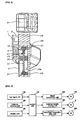
- FIG. 1 is a sectional view showing a conventional automatic balancing rotor for centrifuges.
- the conventional automatic balancing rotor for centrifuges uses a mechanism, in which a lever central body 636 is horizontally moved according to a control algorithm, to compensate for imbalance between samples contained in buckets supported by rotational arms 632.
- the lever moving mechanism includes a worm 662 which is axially coupled to a lever moving motor 652, a worm gear (not shown) which engages with the worm 662, a pinion 666 which is coaxially coupled to the worm gear, and the lever central body 636 having a rack 636a, which engages with the pinion 666.
- a pressure sensor 690 is provided under each rotational arm 632 to measured the weight of the sample contained in the associated bucket (not shown).
- a wiring layer 562 is integrally coupled to a lower part of the rotor to receive an electrical signal from the pressure sensors 690 and transmit an electrical signal to the lever moving motor 652 according to a control algorithm, thus balancing the centrifuge.
- the conventional automatic balancing rotor for centrifuges having the above-mentioned construction senses imbalance of the samples by measuring the weight of the buckets provided at both ends of the rotor lever, and controls the distance between each bucket and a rotating shaft of the rotor according to the weight difference of the samples, thus applying the same centrifugal force to the opposite buckets containing the samples. Thereby, the samples contained in the buckets maintain a dynamic balance state during the rotation of the rotor for centrifugal separation. More details are described in Korean Application No. 10-2002-0017498 (publication date: Apr.17, 2002 ) corresponding to WO 02/083 317 A1 which was filed by the inventor of the present invention, therefore further explanation is deemed unnecessary.
- JP 2002 221256 A discloses an automatic balancing rotor (see figures 5-8 ) comprising a plurality of rotating arms (24,25,26,27) having the same radial length and being arranged around a centrifugal rotating shaft (30), and being spaced out at regular angular intervals, with a plurality of buckets (20,21,22,23) containing samples therein supported by the rotating arms; a balance weight (29a,29b) provided in each of the rotating arms to be movable in a radial direction, thus compensating for imbalanced centrifugal force applied to the buckets during a centrifugal separation; and balance weight moving means (31 a,31 b) to horizontally move the balance weight in the radial direction of each of the rotating arms, in response to vibrations, sensed by an acceleration sensor (39), occurring due to imbalance.
- an object of the present invention is to provide a centrifuge comprising an automatic balancing rotor which compensates for an imbalance of a centrifugal force due to a weight difference of samples by horizontally moving balance weights provided in rotor arms without changing the length of the rotor arms, thus reducing the space that the automatic balancing rotor occupies, and applying the same centrifugal force to the samples contained in the buckets, and preventing the rotor from being affected by back lash during the automatic balancing process.
- a centrifuge comprising an automatic balancing rotor according to the present invention
- imbalance of a centrifugal force of the rotor due to a weight difference of samples is compensated for by controlling rotational radii of balance weights provided in rotor arms. Therefore, vibration of the automatic balancing rotor due to imbalance is prevented from occurring during centrifugal separation, thereby the lifetime of the automatic balancing rotor and of a centrifuge having the rotor is extended, and the samples are prevented from damage.
- the automatic balancing three-arm rotor of the present invention using a balance weight moving method can reduce the space required for centrifugal separation, therefore it is particularly useful in a centrifuge having a large capacity.
- the slot to guide the balance weight can be longitudinally formed through nearly all of the rotor arm, a sufficient balance weight moving distance is ensured, thereby minimizing the effect of back lash occurring between the balance weight and the balance weight moving shaft
- the present invention provides a centrifuge comprising an automatic balancing rotor according to claim 1.
- the buckets may be supported in spaces defined between the rotating arms, respectively.
- each of the rotating arms may include a slot formed through the rotating arm in the radial direction to receive therein the balance weight and guide the horizontal movement of the balance weight.
- the balance weight may have an internal thread formed through a center of the balance weight
- the balance weight moving means may have: a balance weight moving motor, a worm axially coupled to the balance weight moving motor, a worm gear engaging with the worm; and a balance weight moving shaft radially provided in the slot of the rotating arm and having an external thread on an outer surface thereof to engage with the internal thread of the balance weight
- the balance weight moving shaft is coaxially coupled at an end thereof to the worm gear.
- the automatic balancing rotor may further include a reference position sensing means provided at a predetermined position in the slot of the rotating arm to sense the balance weight placed at a reference position.
- FIG. 2 is a perspective view of an automatic balancing rotor for centrifuges, according to an embodiment of the present invention.
- FIG. 3 is an exploded perspective view of the automatic balancing rotor of FIG. 2 .
- FIG. 4 is a sectional view of the rotor taken along the line A-A of FIG. 2 .
- a three-arm swing rotor is shown as an example. As shown in FIGS.
- the automatic balancing rotor for centrifuges includes three rotor arms 29 which support a plurality of buckets 31 containing samples therein
- the automatic balancing rotor further includes a balance weight 15 which is provided in each of the rotor arms 29 to compensate for imbalanced centrifugal force applied to the buckets 31 during a centrifugal separation" and a balance weight moving means to horizontally move each balance weight 15 in the radial direction of each rotating arm 29.
- the rotor arms 29 are formed by cutting portions of a circular plate having a predetermined thickness at regular angular intervals, so that the buckets 31 are disposed in the cut portions.
- the rotor arms 29 are spaced out at 120° intervals.
- a pair of bucket support pins 33 is provided on opposite sidewalls of each rotor arm 29 to rotatably support each bucket 31.
- each bucket 31 is supported by the cooperation of two adjacent rotor arms 29.
- a slot 29a is formed through each rotating arm 29 in the radial direction to receive therein each balance weight 15 and guide the horizontal movement of the balance weight 15.
- the slot 29a has an elongated rectangular hole shape.
- the balance weight 15 have a hexahedral shape to prevent the balance weight 15 from rolling in the slot 29a
- An internal thread (not shown) is formed through the center of each balance weight 15.
- Each balance weight moving means has a balance weight moving motor 5 which is provided on a central portion of the automatic balancing rotor such that an output shaft of the balance weight moving motor 5 is vertically disposed.
- the balance weight moving means further has a worm 7 which is axially coupled to an end of the output shaft of the balance weight moving motor 5, and a balance weight moving shaft 17 which is longitudinally provided in the slot 29a of the rotor arm 29.
- the balance weight moving shaft 17 has an external thread on an outer surface thereof that engages with the internal thread of the balance weight 15.
- the balance weight moving means further has a worm gear 19 which is axially coupled to an end of the balance weight moving shaft 17 and engages with the worm 7, and a thrust bearing 21 and a radial bearing 23 which are coaxially coupled to opposite ends of the balance weight moving shaft 17.
- a reference position sensor 13 preferably a limit switch, is required.
- a reference position sensor 13 is provided at a predetermined position in each slot 29a.
- the reference position sensor 13 is mounted to a support bracket 11 which extends a predetermined length downwards from a slot cover 9.
- the reference numerals 3 and 1 respectively denote a support frame to support therein the balance weight moving motors 5, and a motor cap to cover the support frame 3.
- the reference numeral 9 denotes a slot cover to cover an open upper end of each slot 29a.
- the reference numerals 25 and 27 denote bearing supports to support each thrust bearing 21 and each radial bearing 23 in each slot 29a, respectively
- FIG. 5 is an electrical block diagram of the operation of a centrifuge having the automatic balancing rotor of the present invention.
- an electrical construction of the centrifuge having the automatic balancing rotor of the present invention includes a key input unit 110 to select and input various functions provided by the centrifuge having the automatic balancing rotor, and a balance sensing unit 120 which has a weight measuring apparatus (not shown) provided in the centrifuge and senses the weight of the samples contained in the buckets 31, which are supported by the rotor arms 29.
- the electrical construction of the centrifuge further includes a display unit 130 which displays information about the operation of the centrifuge on a display panel, and a control unit 100 which controls the entire operation of the centrifuge.
- the electrical construction of the centrifuge further includes a balance weight moving unit 150 which moves the balance weight 17 by driving the balance weight moving motor 5 along the balance weight moving shaft 17 from an initial position that is sensed by the reference position sensor 13.
- the electrical construction of the centrifuge further includes a signal connection unit 140 which connects a wiring connection board (not shown) to a wiring layer (not shown) by driving a wiring layer connection motor 170, thus forming an electrical system capable of transmitting a control command to the balance weight moving unit 150 according to a sensing signal from the balance sensing unit 120.
- the electrical, construction of the centrifuge further includes a centrifugal separation drive unit 160 which rotates the three-arm swing rotor supporting the buckets 31 therein by driving a rotor drive motor 180.
- the balance weight moving motor 5 may be embodied by a stepping motor which is able to precisely control its rotation angle.
- the balance weight moving motor 5 may be embodied by a servomotor.
- the control unit 100 includes a balance weight moving distance calculating equation (see equation 1 which will be disclosed herein later) using the difference in weight of the samples, thus calculating the distance to move the balance weight 15 along the balance weight moving shaft 17 using the rotation of the balance weight moving motor 5.
- a user puts adaptors (not shown) containing samples in three buckets 31 supported by the bucket support pins 33 of the rotor arms 29. Thereafter, the user inputs a control command suitable to a centrifugal separating condition for each sample using the key input unit 110. Then, the control unit 100 transmits the control command to the balance sensing unit 120.
- the weight measuring apparatus having a weight measuring sensor (not shown) measures the weight of the samples contained in the buckets 31 after spatially isolating the buckets 31 from the bucket support pins 33 by raising the buckets 31 upwards.
- control unit 100 receives a signal about the weight of the samples measured by the balance sensing unit 120, and calculates a moving distance of each balance weight 15 to compensate for imbalance of the weight of the samples.
- control unit 100 transmits a control command to the signal connection unit 140, thus driving the wiring layer connection motor 170, so that the wiring connection board (not shown) is connected to the wiring layer (not shown).
- the control unit 100 first determines whether each balance weight 15 is placed at the initial reference position or not through a signal received from each reference position sensor 13 through the signal connection unit 140. Here, if a signal from a reference position sensor 13 indicates that the associated balance weight 15 is placed at an initial reference position, the control unit 100 transmits a control command to the balance weight moving unit 150 through the connected signal connection unit 140 to control the rotation angle of the associated balance weight moving motor 5. As a result of this, the balance weight 15 is advanced by the calculated distance along the balance weight moving shaft 17.
- the control unit 100 transmits a control command to the balance weight moving unit 150 through the connected signal connection unit 140 to control the rotation angle of the associated balance weight moving motor 5 in a desired direction. Then, the balance weight 15 is retracted along the balance weight moving shaft 17 to the initial reference position.
- the control unit 100 continuously reads a signal from the reference position sensor 13 and determines whether the balance weight 15 reaches the initial reference position or not
- the control unit 100 immediately stops the control signal, which has been transmitter to the balance weight moving motor 5, and reversely rotates the balance weight moving motor 5, thus advancing the balance weight 15 by the calculated distance along the balance weight moving shafts 17.
- the control unit 100 transmits a control command to the signal connection unit 140 to drive the wiring layer connection motor 170, thus separating the wiring connection board from the wiring layer.
- the control unit 100 transmits a control command to the centrifugal separation drive unit 160 to drive the rotor drive motor 180.
- the centrifuge executes a centrifugal separation process in a balanced state.
- the display unit 130 displays various kinds of information about both a current setting and operational conditions on the display panel during the centrifugal separation.
- the moving distance of each balance weight 15 is calculated using the weight difference among the buckets 31 containing the samples which is measured by the weight measuring apparatus, so as to compensate for imbalance of the centrifugal force among the buckets 31 occurring due to the weight difference.
- This calculation of the balance weight moving distance is executed through a process which will be described step by step. First, the centrifugal force of each bucket 31, when rotated, is obtained from the weight of the bucket 31, the distance between the bucket 31 and the rotating shaft of the rotor, and the set rotating speed.
- a vector value of a total centrifugal force of the buckets 31 is obtained by summing vectors of the centrifugal forces of the buckets 31.
- a centrifugal force of each balance weight 15 can be determined from the weight of the balance weight 15, a distance between the balance weight 15 and the rotating shaft ofthe rotor to be induced, and the set rotating speed.
- a vector value of a total centrifugal force of the balance weights 15 can be calculated by summing vectors of the centrifugal forces of the balance weights 15. To balance the centrifuge during the centrifugal separation, a dynamic balance must be maintained between the total centrifugal force vector of the buckets 31 which acts as an imbalancing factor due to the samples contained in the buckets 31, and the total centrifugal force vector of the balance weights 15 which compensates for or offsets the total centrifugal force vector ofthe buckets 31.
- a distance to move each balance weight 15 along each balance weight moving shaft 17 is obtained using a relational expression for the dynamic balance between the total centrifugal force of the buckets 31 and the total centrifugal force of the balance weights 15.
- the factors m b,i and m cw denote the weight of each bucket 31 and the weight of each balance weight 15, respectively.
- the factors r b,i and r cw,i denote position vectors from the rotating shaft of the rotor toward centers of mass of the bucket 31 and the balance weight 15, respectively.
- the factor ⁇ denotes a rotating speed of the automatic balancing rotor.
- the equation 1 is for a three-arm rotor.
- the equation 1 shows that the left side, that is, the sum of centrifugal force vectors of three buckets 31 containing the samples, must be the same as that of the right side, that is, the sum of centrifugal force vectors of three balance weights 1, so that the total centrifugal force among them must theoretically become zero. From the equation 1, the distance r cw,i that each balance weight 15 is moved can be obtained.
- the wiring layer (not shown), which is connected to an electrical circuit of both the balance weight moving motor 5 and the reference position sensors 13, is disposed around an output shaft of the rotor drive motor 180. Accordingly, in a state in which the output shaft of the rotor drive motor 180 is rotated at an appropriate angle, the wiring layer is removably connected to the wiring connection board (not shown) without the entanglement of electrical wires near the rotor arms 29.
- each balance weight moving motor 5 is axially coupled to each worm 7 to move the associated balance weight 15 along the associated balance weight moving shaft 17.
- the worm 7 engages with the associated worm gear 19 at an appropriate gear ratio.
- the worm gear 19 can be driven by the rotation of the worm 7, but the worm 7 cannot be reversely rotated by the rotation of the worm gear 19. Therefore, even when the rotor arms 29 rotate at high speed, the balance weights 15 are prevented from undesirably moving along the balance weight moving shafts 17 outwards due to the centrifugal force.
- centrifuge comprising an automatic balancing rotor according to the present invention is not limited to the above-mentioned embodiment, and various modifications are possible, without departing from the scope of the invention as defined by the appended claim 5.
- a two-arm swing rotor, a four-arm swing rotor or a swing rotor having five arms or more may be used in a centrifuge, in place of the three-arm swing rotor shown in the above-mentioned embodiment
- rotor arms are spaced out at 180° intervals.
- rotor arms are spaced out at 90° intervals.
- balance weight moving units having the same structure must be provided in slots of rotor arms.
- an engagement ofbevel gears or other gears may be used as a balance weight moving unit to control the movement of the balance weights 15 in place of the engagement of the worm 7 and the worm gear 19.
- a multiple bearing may be used in the balance weight moving unit, in place of the thrust bearing 21 and the radial bearing 23 to support the balance weight moving shaft 17, to help smoothly rotate the balance weight moving shaft 17, and to sustain the centrifugal force of the balance weights.
- it may be embodied by combined application of the thrust bearing 21 and the radial bearing 23.
Landscapes
- Centrifugal Separators (AREA)
Claims (4)
- Zentrifuge, umfassend:einen automatischen Ausgleichsrotor, der Folgendes umfasst:eine Mehrzahl von rotierenden Armen (29), die dieselbe radiale Länge aufweisen und um eine zentrifugale rotierende Welle herum angeordnet sind, und die bei regelmäßigen Winkelintervallen verteilt sind, mit einer Mehrzahl von Eimern (31), die Proben darin enthalten, die von den rotierenden Armen (29) getragen werden,ein Ausgleichsgewicht (15), das in jedem der rotierenden Arme (29) bereitgestellt ist, um in einer radialen Richtung beweglich zu sein, um folglich eine unausgeglichene Zentrifugalkraft zu kompensieren, die auf die Eimer (31) während einer zentrifugalen Trennung angewendet wird, undAusgleichsgewichtbewegungsmittel zum horizontalen Bewegen des Ausgleichsgewichts (15) in der radialen Richtung jedes der rotierenden Arme (29);eine Gewichtmessvorrichtung zum Messen des Gewichts von jeder in den Eimern (31) enthaltenen Probe; undeine Steuereinheit (100) zum Berechnen der Distanz, um die jedes Ausgleichsgewicht (15) zu bewegen ist, mittels der Differenz im Gewicht jeder Probe.
- Zentrifuge nach Anspruch 1, wobei die Eimer (31) in Räumen getragen werden, die jeweils zwischen den rotierenden Armen (29) definiert werden.
- Zentrifuge nach Anspruch 1, wobei:jeder der rotierenden Arme (29) einen Schlitz (29a) umfasst, der durch den rotierenden Arm (29) in der radialen Richtung gebildet ist, um darin das Ausgleichsgewicht (15) aufzunehmen und die horizontale Bewegung des Ausgleichsgewichts (15) zu führen,das Ausgleichsgewicht (15) ein Innengewinde aufweist, das durch ein Zentrum des Ausgleichsgewichts (15) gebildet ist, unddie Ausgleichsgewichtbewegungsmittel Folgendes umfassen:einen Ausgleichsgewichtbewegungsmotor (5);eine Schnecke (7), die axial an den Ausgleichsgewichtbewegungsmotor (5) gekoppelt ist;ein Schneckengetriebe (19), das mit der Schnecke (7) in Eingriff steht; undeine Ausgleichsgewichtbewegungswelle (17), die radial im Schlitz (29a) des rotierenden Arms (29) bereitgestellt ist, und die ein Außengewinde auf einer äußeren Oberfläche davon aufweist, um mit dem Innengewinde des Ausgleichsgewichts (15) in Eingriff zu stehen, wobei die Ausgleichsgewichtbewegungswelle (17) koaxial bei einem Ende davon an das Schneckengetriebe (19) gekoppelt ist.
- Zentrifuge nach einem der Ansprüche 1 bis 3, wobei der automatische Ausgleichsrotor ferner umfasst:Referenzpositionserfassungsmittel, die bei einer vorbestimmten Position im Schlitz (29a) des rotierenden Arms (29) bereitgestellt sind, um das Ausgleichsgewicht (15), platziert bei einer Referenzposition, zu erfassen.
Applications Claiming Priority (2)
| Application Number | Priority Date | Filing Date | Title |
|---|---|---|---|
| KR1020040076489A KR100615630B1 (ko) | 2004-09-23 | 2004-09-23 | 원심 분리기용 자동 평형형 로터 |
| PCT/KR2004/003011 WO2006033502A1 (en) | 2004-09-23 | 2004-11-19 | Automatic balancing rotor for centrifuge |
Publications (3)
| Publication Number | Publication Date |
|---|---|
| EP1667799A1 EP1667799A1 (de) | 2006-06-14 |
| EP1667799A4 EP1667799A4 (de) | 2007-04-11 |
| EP1667799B1 true EP1667799B1 (de) | 2008-09-10 |
Family
ID=36090235
Family Applications (1)
| Application Number | Title | Priority Date | Filing Date |
|---|---|---|---|
| EP04821366A Expired - Lifetime EP1667799B1 (de) | 2004-09-23 | 2004-11-19 | Zentrifuge mit automatischem ausgleichsrotor |
Country Status (10)
| Country | Link |
|---|---|
| US (1) | US7285085B2 (de) |
| EP (1) | EP1667799B1 (de) |
| JP (1) | JP4440892B2 (de) |
| KR (1) | KR100615630B1 (de) |
| CN (1) | CN100455358C (de) |
| AT (1) | ATE407741T1 (de) |
| AU (1) | AU2004313215B2 (de) |
| CA (1) | CA2520198C (de) |
| DE (1) | DE602004016538D1 (de) |
| WO (1) | WO2006033502A1 (de) |
Families Citing this family (35)
| Publication number | Priority date | Publication date | Assignee | Title |
|---|---|---|---|---|
| FR2842912B1 (fr) * | 2002-07-25 | 2004-09-10 | Junior Instruments | Procede et dispositf pour le pretraitement par centrifugeage d'echantillons. |
| KR20050101600A (ko) * | 2004-04-19 | 2005-10-25 | 주식회사 한랩 | 원심 분리기 |
| KR100615630B1 (ko) * | 2004-09-23 | 2006-09-19 | 주식회사 한랩 | 원심 분리기용 자동 평형형 로터 |
| KR100606264B1 (ko) * | 2004-11-19 | 2006-07-31 | 주식회사 한랩 | 유체 보상에 의한 자동 평형형 원심분리 장치 |
| KR100756231B1 (ko) * | 2006-02-24 | 2007-09-06 | 주식회사 한랩 | 원심분리기용 자동평형형 로터 |
| US20090209404A1 (en) * | 2008-02-15 | 2009-08-20 | Greene Roger L | Mechanism for generating directional thrust from a centrifuge |
| KR100986744B1 (ko) | 2008-07-10 | 2010-10-08 | 주식회사 한랩 | 자동 평형형 원심분리기 및 그 제어 방법 |
| KR100978912B1 (ko) * | 2008-07-10 | 2010-08-31 | 주식회사 한랩 | 자동 평형형 원심분리기 |
| DE102009040525B4 (de) * | 2009-09-08 | 2015-02-05 | Andreas Hettich Gmbh & Co. Kg | Zentrifuge zum Trennen von Vollblut in Blutkomponenten, sowie fluidisch kommunizierende Behälter zum Einsetzen in die Zentrifuge, sowie Verfahren zur Gewinnung eines hochangereichten Thrombozytenkonzentrats aus Vollblut |
| US9039992B2 (en) * | 2011-06-06 | 2015-05-26 | Abbott Laboratories | Apparatus for closed tube sampling and open tube sampling for automated clinical analyzers |
| DE102011054766A1 (de) * | 2011-10-24 | 2013-04-25 | Andreas Hettich Gmbh & Co. Kg | Verfahren zum automatischen Beladen einer Zentrifuge mit Probenbehältern |
| MX377915B (es) * | 2014-01-22 | 2025-03-10 | Labrador Diagnostics Llc | Centrifuga compacta de alta velocidad para utilizarse con pequeños volumenes de muestra. |
| JP6435778B2 (ja) * | 2014-10-30 | 2018-12-12 | 工機ホールディングス株式会社 | 遠心機用スイングロータ及び遠心機 |
| DE102015100613A1 (de) * | 2015-01-16 | 2016-07-21 | Andreas Hettich Gmbh & Co. Kg | Rotor einer Dualen Zentrifuge |
| ES2989325T3 (es) * | 2015-04-05 | 2024-11-26 | Arteriocyte Medical Systems Inc | Contrapeso de centrifugadora con centro de gravedad ajustable y procedimientos para utilizar el mismo |
| US10967389B2 (en) | 2015-11-23 | 2021-04-06 | Fenwal, Inc. | Systems and methods for automatically balancing a centrifuge |
| CN105498983B (zh) * | 2015-12-31 | 2017-10-03 | 宁夏东吴农化有限公司 | 一种自平衡化工离心机 |
| CN106964499B (zh) * | 2017-04-11 | 2018-09-21 | 河南工程学院 | 具有配重和收集功能的高速离心机 |
| DE102017123082A1 (de) * | 2017-10-05 | 2019-04-11 | Vorwerk & Co. Interholding Gmbh | Außenläufermotor |
| CN108176522B (zh) * | 2017-11-30 | 2020-04-07 | 海南出入境检验检疫局检验检疫技术中心 | 一种具有自平衡功能的食品检测用离心机 |
| CN116251658A (zh) * | 2018-04-04 | 2023-06-13 | 乔迪·G·罗宾斯 | 按比重分离矿物 |
| US12151251B2 (en) * | 2018-11-20 | 2024-11-26 | Tecan Trading Ag | Centrifugal processing unit |
| CN109465117B (zh) * | 2018-12-27 | 2023-05-30 | 中国工程物理研究院总体工程研究所 | 整体式离心机动态配平装置及配平方法 |
| JP7473176B2 (ja) * | 2019-06-10 | 2024-04-23 | 株式会社セルピック | 臍帯血用バッグセット、および、臍帯血用遠心機 |
| CN110254754B (zh) * | 2019-06-24 | 2021-01-15 | 北京机械设备研究所 | 一种空间旋转释放装置及旋转释放方法 |
| CN110947526A (zh) * | 2019-12-10 | 2020-04-03 | 杭州医学院 | 一种可自动配平离心机 |
| JP7837144B2 (ja) * | 2020-05-29 | 2026-03-30 | ファイバーライト・セントリフュージ・エルエルシー | 遠心分離機ロータのバランシングを行うためのシステムおよび方法 |
| CN113751212B (zh) * | 2021-09-28 | 2025-03-14 | 金西盟干细胞(天津)有限责任公司 | 一种具有自动调平衡转子结构的离心机及其使用方法 |
| CN114682395A (zh) * | 2022-04-07 | 2022-07-01 | 赵宏英 | 一种富血小板血浆自动制备装置 |
| WO2024112811A2 (en) | 2022-11-23 | 2024-05-30 | Good Earth Ip Holdings, Llc | Separation of minerals by gas injection |
| CN116673135B (zh) * | 2023-05-30 | 2025-10-31 | 武汉兰丁云医学检验实验室有限公司 | 可切换配重的内部补偿式细胞组织离心装置 |
| KR102855220B1 (ko) * | 2023-08-24 | 2025-09-05 | 인하대학교 산학협력단 | 자기유변탄성체를 이용한 원심분리기용 자동 평형 장치 |
| KR102736387B1 (ko) | 2023-09-14 | 2024-11-29 | 주식회사 한랩 | 자동 평형 원심분리기 및 이의 제어방법 |
| EP4578553A4 (de) * | 2023-10-31 | 2026-03-11 | Rorze Lifescience Inc | Zentrifuge und verfahren zur einstellung des schwerpunkts des rotors einer zentrifuge |
| CN119926682B (zh) * | 2025-03-13 | 2026-02-17 | 西安捷盛电子技术有限责任公司 | 一种离心机的配平装置 |
Family Cites Families (19)
| Publication number | Priority date | Publication date | Assignee | Title |
|---|---|---|---|---|
| US3834613A (en) * | 1971-03-01 | 1974-09-10 | Int Equipment Co | Centrifuge rotor with sample holding means and means for balancing the same |
| US4157781A (en) * | 1978-07-19 | 1979-06-12 | Hitoshi Maruyama | Self balancing centrifuge |
| US4412831A (en) * | 1981-07-09 | 1983-11-01 | Haemonetics Corporation | Two plane self-balancing centrifuge |
| US4435168A (en) * | 1982-06-04 | 1984-03-06 | Damon Corporation | Centrifuge rotor apparatus with sling arms |
| SE8304901D0 (sv) * | 1983-09-13 | 1983-09-13 | Alfa Laval Separation Ab | Anordning for balansering av rotorn hos en centrifugalseparator |
| JPH0667493B2 (ja) * | 1986-09-02 | 1994-08-31 | 三菱化成株式会社 | 遠心用自動平衡装置付ロ−タ− |
| FR2625923B1 (fr) * | 1988-01-18 | 1992-02-21 | Acutronic France Sa | Dispositif d'equilibrage automatique d'une centrifugeuse en fonctionnement |
| JPH03293047A (ja) * | 1990-04-06 | 1991-12-24 | Hitachi Koki Co Ltd | 自動遠心分離機 |
| US5207634A (en) * | 1991-01-23 | 1993-05-04 | Biotope, Inc. | Self-balancing apparatus and method for a centrifuge device |
| JP3293047B2 (ja) * | 1993-02-26 | 2002-06-17 | オムロン株式会社 | 電動式パワーステアリング装置 |
| JP2002221256A (ja) * | 2000-11-22 | 2002-08-09 | Mitsubishi Heavy Ind Ltd | 微小重力回転装置 |
| KR100470068B1 (ko) * | 2001-04-02 | 2005-02-05 | 주식회사 한랩 | 자동 평형형 원심 분리 장치 |
| JP2003236409A (ja) * | 2002-02-15 | 2003-08-26 | Yasuyuki Yokoyama | 自己バランスを有する回転体と回転装置 |
| FR2842912B1 (fr) * | 2002-07-25 | 2004-09-10 | Junior Instruments | Procede et dispositf pour le pretraitement par centrifugeage d'echantillons. |
| FR2858251B1 (fr) * | 2003-07-29 | 2005-10-28 | Diagyr | Procede pour equilibrer un plateau rotatif d'une centrifugeuse et centrifugeuse mettant en oeuvre le procede |
| KR20050101600A (ko) * | 2004-04-19 | 2005-10-25 | 주식회사 한랩 | 원심 분리기 |
| KR100615630B1 (ko) * | 2004-09-23 | 2006-09-19 | 주식회사 한랩 | 원심 분리기용 자동 평형형 로터 |
| KR100606264B1 (ko) * | 2004-11-19 | 2006-07-31 | 주식회사 한랩 | 유체 보상에 의한 자동 평형형 원심분리 장치 |
| KR102001749B1 (ko) | 2015-02-11 | 2019-07-18 | 아브 이니티오 테크놀로지 엘엘시 | 필터링 데이터 계통 다이어그램 |
-
2004
- 2004-09-23 KR KR1020040076489A patent/KR100615630B1/ko not_active Expired - Fee Related
- 2004-11-19 JP JP2005518110A patent/JP4440892B2/ja not_active Expired - Lifetime
- 2004-11-19 CA CA002520198A patent/CA2520198C/en not_active Expired - Fee Related
- 2004-11-19 AU AU2004313215A patent/AU2004313215B2/en not_active Ceased
- 2004-11-19 US US10/547,476 patent/US7285085B2/en not_active Expired - Fee Related
- 2004-11-19 WO PCT/KR2004/003011 patent/WO2006033502A1/en not_active Ceased
- 2004-11-19 EP EP04821366A patent/EP1667799B1/de not_active Expired - Lifetime
- 2004-11-19 AT AT04821366T patent/ATE407741T1/de not_active IP Right Cessation
- 2004-11-19 CN CNB2004800055935A patent/CN100455358C/zh not_active Expired - Fee Related
- 2004-11-19 DE DE602004016538T patent/DE602004016538D1/de not_active Expired - Lifetime
Also Published As
| Publication number | Publication date |
|---|---|
| US20060252627A1 (en) | 2006-11-09 |
| WO2006033502A1 (en) | 2006-03-30 |
| KR100615630B1 (ko) | 2006-09-19 |
| EP1667799A4 (de) | 2007-04-11 |
| EP1667799A1 (de) | 2006-06-14 |
| JP4440892B2 (ja) | 2010-03-24 |
| KR20060027614A (ko) | 2006-03-28 |
| AU2004313215A1 (en) | 2006-04-06 |
| AU2004313215B2 (en) | 2010-05-13 |
| CA2520198A1 (en) | 2006-03-23 |
| ATE407741T1 (de) | 2008-09-15 |
| US7285085B2 (en) | 2007-10-23 |
| CA2520198C (en) | 2009-05-19 |
| DE602004016538D1 (de) | 2008-10-23 |
| CN1812842A (zh) | 2006-08-02 |
| HK1089406A1 (zh) | 2006-12-01 |
| CN100455358C (zh) | 2009-01-28 |
| JP2008518747A (ja) | 2008-06-05 |
Similar Documents
| Publication | Publication Date | Title |
|---|---|---|
| US7285085B2 (en) | Automatic balancing rotor for centrifuge | |
| KR100470068B1 (ko) | 자동 평형형 원심 분리 장치 | |
| AU2002243085A1 (en) | Automatic balance adjusting centrifugal apparatus | |
| KR20100006760A (ko) | 자동 평형형 원심분리기 및 그 제어 방법 | |
| US7195737B2 (en) | Specimen centrifuge system | |
| US8262551B2 (en) | Centrifuge having displacement sensor | |
| US20070203010A1 (en) | Automatic balance adjustable rotor for centrifuge apparatus | |
| HK1089406B (en) | Automatic balancing rotor for centrifuge | |
| EP3744430B1 (de) | Zentrifuge | |
| KR100343336B1 (ko) | 자동 평형형 원심 분리 장치 | |
| JPH03293047A (ja) | 自動遠心分離機 | |
| JP2008212903A (ja) | 遠心分離機 | |
| KR102736387B1 (ko) | 자동 평형 원심분리기 및 이의 제어방법 | |
| JP2007326040A (ja) | 遠心機 | |
| JPH11320333A (ja) | カウンタウェイトを備えるフェーシングマシンおよびその位置制御方法 | |
| SU1291832A1 (ru) | Стенд дл испытани подшипников качени | |
| CN121499841A (zh) | 一种离心和孵育一体检测装置及方法 | |
| JPH08141436A (ja) | 遠心分離装置 | |
| HK1065741B (en) | Automatic balance centrifugal apparatus |
Legal Events
| Date | Code | Title | Description |
|---|---|---|---|
| PUAI | Public reference made under article 153(3) epc to a published international application that has entered the european phase |
Free format text: ORIGINAL CODE: 0009012 |
|
| 17P | Request for examination filed |
Effective date: 20050830 |
|
| AK | Designated contracting states |
Kind code of ref document: A1 Designated state(s): AT BE BG CH CY CZ DE DK EE ES FI FR GB GR HU IE IS IT LI LU MC NL PL PT RO SE SI SK TR |
|
| AX | Request for extension of the european patent |
Extension state: AL HR LT LV MK YU |
|
| A4 | Supplementary search report drawn up and despatched |
Effective date: 20070308 |
|
| RIC1 | Information provided on ipc code assigned before grant |
Ipc: B04B 9/14 20060101AFI20070302BHEP Ipc: B04B 5/04 20060101ALI20070302BHEP |
|
| 17Q | First examination report despatched |
Effective date: 20070620 |
|
| DAX | Request for extension of the european patent (deleted) | ||
| GRAP | Despatch of communication of intention to grant a patent |
Free format text: ORIGINAL CODE: EPIDOSNIGR1 |
|
| RTI1 | Title (correction) |
Free format text: CENTRIFUGE WITH AUTOMATIC BALANCING ROTOR |
|
| GRAS | Grant fee paid |
Free format text: ORIGINAL CODE: EPIDOSNIGR3 |
|
| GRAA | (expected) grant |
Free format text: ORIGINAL CODE: 0009210 |
|
| AK | Designated contracting states |
Kind code of ref document: B1 Designated state(s): AT BE BG CH CY CZ DE DK EE ES FI FR GB GR HU IE IS IT LI LU MC NL PL PT RO SE SI SK TR |
|
| REG | Reference to a national code |
Ref country code: GB Ref legal event code: FG4D |
|
| REG | Reference to a national code |
Ref country code: CH Ref legal event code: EP |
|
| REG | Reference to a national code |
Ref country code: IE Ref legal event code: FG4D |
|
| REF | Corresponds to: |
Ref document number: 602004016538 Country of ref document: DE Date of ref document: 20081023 Kind code of ref document: P |
|
| PG25 | Lapsed in a contracting state [announced via postgrant information from national office to epo] |
Ref country code: FI Free format text: LAPSE BECAUSE OF FAILURE TO SUBMIT A TRANSLATION OF THE DESCRIPTION OR TO PAY THE FEE WITHIN THE PRESCRIBED TIME-LIMIT Effective date: 20080910 Ref country code: SI Free format text: LAPSE BECAUSE OF FAILURE TO SUBMIT A TRANSLATION OF THE DESCRIPTION OR TO PAY THE FEE WITHIN THE PRESCRIBED TIME-LIMIT Effective date: 20080910 Ref country code: AT Free format text: LAPSE BECAUSE OF FAILURE TO SUBMIT A TRANSLATION OF THE DESCRIPTION OR TO PAY THE FEE WITHIN THE PRESCRIBED TIME-LIMIT Effective date: 20080910 |
|
| NLV1 | Nl: lapsed or annulled due to failure to fulfill the requirements of art. 29p and 29m of the patents act | ||
| PG25 | Lapsed in a contracting state [announced via postgrant information from national office to epo] |
Ref country code: BE Free format text: LAPSE BECAUSE OF FAILURE TO SUBMIT A TRANSLATION OF THE DESCRIPTION OR TO PAY THE FEE WITHIN THE PRESCRIBED TIME-LIMIT Effective date: 20080910 |
|
| PG25 | Lapsed in a contracting state [announced via postgrant information from national office to epo] |
Ref country code: BG Free format text: LAPSE BECAUSE OF FAILURE TO SUBMIT A TRANSLATION OF THE DESCRIPTION OR TO PAY THE FEE WITHIN THE PRESCRIBED TIME-LIMIT Effective date: 20081210 Ref country code: ES Free format text: LAPSE BECAUSE OF FAILURE TO SUBMIT A TRANSLATION OF THE DESCRIPTION OR TO PAY THE FEE WITHIN THE PRESCRIBED TIME-LIMIT Effective date: 20081221 |
|
| PG25 | Lapsed in a contracting state [announced via postgrant information from national office to epo] |
Ref country code: NL Free format text: LAPSE BECAUSE OF FAILURE TO SUBMIT A TRANSLATION OF THE DESCRIPTION OR TO PAY THE FEE WITHIN THE PRESCRIBED TIME-LIMIT Effective date: 20080910 Ref country code: CZ Free format text: LAPSE BECAUSE OF FAILURE TO SUBMIT A TRANSLATION OF THE DESCRIPTION OR TO PAY THE FEE WITHIN THE PRESCRIBED TIME-LIMIT Effective date: 20080910 Ref country code: RO Free format text: LAPSE BECAUSE OF FAILURE TO SUBMIT A TRANSLATION OF THE DESCRIPTION OR TO PAY THE FEE WITHIN THE PRESCRIBED TIME-LIMIT Effective date: 20080910 Ref country code: SK Free format text: LAPSE BECAUSE OF FAILURE TO SUBMIT A TRANSLATION OF THE DESCRIPTION OR TO PAY THE FEE WITHIN THE PRESCRIBED TIME-LIMIT Effective date: 20080910 Ref country code: IS Free format text: LAPSE BECAUSE OF FAILURE TO SUBMIT A TRANSLATION OF THE DESCRIPTION OR TO PAY THE FEE WITHIN THE PRESCRIBED TIME-LIMIT Effective date: 20090110 |
|
| PG25 | Lapsed in a contracting state [announced via postgrant information from national office to epo] |
Ref country code: MC Free format text: LAPSE BECAUSE OF NON-PAYMENT OF DUE FEES Effective date: 20081130 |
|
| REG | Reference to a national code |
Ref country code: CH Ref legal event code: PL |
|
| PLBE | No opposition filed within time limit |
Free format text: ORIGINAL CODE: 0009261 |
|
| STAA | Information on the status of an ep patent application or granted ep patent |
Free format text: STATUS: NO OPPOSITION FILED WITHIN TIME LIMIT |
|
| PG25 | Lapsed in a contracting state [announced via postgrant information from national office to epo] |
Ref country code: EE Free format text: LAPSE BECAUSE OF FAILURE TO SUBMIT A TRANSLATION OF THE DESCRIPTION OR TO PAY THE FEE WITHIN THE PRESCRIBED TIME-LIMIT Effective date: 20080910 Ref country code: DK Free format text: LAPSE BECAUSE OF FAILURE TO SUBMIT A TRANSLATION OF THE DESCRIPTION OR TO PAY THE FEE WITHIN THE PRESCRIBED TIME-LIMIT Effective date: 20080910 |
|
| 26N | No opposition filed |
Effective date: 20090611 |
|
| REG | Reference to a national code |
Ref country code: IE Ref legal event code: MM4A |
|
| PG25 | Lapsed in a contracting state [announced via postgrant information from national office to epo] |
Ref country code: IT Free format text: LAPSE BECAUSE OF FAILURE TO SUBMIT A TRANSLATION OF THE DESCRIPTION OR TO PAY THE FEE WITHIN THE PRESCRIBED TIME-LIMIT Effective date: 20080910 |
|
| PG25 | Lapsed in a contracting state [announced via postgrant information from national office to epo] |
Ref country code: IE Free format text: LAPSE BECAUSE OF NON-PAYMENT OF DUE FEES Effective date: 20081119 Ref country code: CH Free format text: LAPSE BECAUSE OF NON-PAYMENT OF DUE FEES Effective date: 20081130 Ref country code: LI Free format text: LAPSE BECAUSE OF NON-PAYMENT OF DUE FEES Effective date: 20081130 |
|
| PG25 | Lapsed in a contracting state [announced via postgrant information from national office to epo] |
Ref country code: SE Free format text: LAPSE BECAUSE OF FAILURE TO SUBMIT A TRANSLATION OF THE DESCRIPTION OR TO PAY THE FEE WITHIN THE PRESCRIBED TIME-LIMIT Effective date: 20081210 |
|
| PG25 | Lapsed in a contracting state [announced via postgrant information from national office to epo] |
Ref country code: PL Free format text: LAPSE BECAUSE OF FAILURE TO SUBMIT A TRANSLATION OF THE DESCRIPTION OR TO PAY THE FEE WITHIN THE PRESCRIBED TIME-LIMIT Effective date: 20080910 |
|
| PG25 | Lapsed in a contracting state [announced via postgrant information from national office to epo] |
Ref country code: HU Free format text: LAPSE BECAUSE OF FAILURE TO SUBMIT A TRANSLATION OF THE DESCRIPTION OR TO PAY THE FEE WITHIN THE PRESCRIBED TIME-LIMIT Effective date: 20090311 Ref country code: CY Free format text: LAPSE BECAUSE OF FAILURE TO SUBMIT A TRANSLATION OF THE DESCRIPTION OR TO PAY THE FEE WITHIN THE PRESCRIBED TIME-LIMIT Effective date: 20080910 Ref country code: LU Free format text: LAPSE BECAUSE OF NON-PAYMENT OF DUE FEES Effective date: 20081119 |
|
| PG25 | Lapsed in a contracting state [announced via postgrant information from national office to epo] |
Ref country code: TR Free format text: LAPSE BECAUSE OF FAILURE TO SUBMIT A TRANSLATION OF THE DESCRIPTION OR TO PAY THE FEE WITHIN THE PRESCRIBED TIME-LIMIT Effective date: 20080910 |
|
| PG25 | Lapsed in a contracting state [announced via postgrant information from national office to epo] |
Ref country code: GR Free format text: LAPSE BECAUSE OF FAILURE TO SUBMIT A TRANSLATION OF THE DESCRIPTION OR TO PAY THE FEE WITHIN THE PRESCRIBED TIME-LIMIT Effective date: 20081211 |
|
| PG25 | Lapsed in a contracting state [announced via postgrant information from national office to epo] |
Ref country code: PT Free format text: LAPSE BECAUSE OF FAILURE TO SUBMIT A TRANSLATION OF THE DESCRIPTION OR TO PAY THE FEE WITHIN THE PRESCRIBED TIME-LIMIT Effective date: 20080910 |
|
| PGFP | Annual fee paid to national office [announced via postgrant information from national office to epo] |
Ref country code: GB Payment date: 20131113 Year of fee payment: 10 Ref country code: FR Payment date: 20131108 Year of fee payment: 10 |
|
| GBPC | Gb: european patent ceased through non-payment of renewal fee |
Effective date: 20141119 |
|
| REG | Reference to a national code |
Ref country code: FR Ref legal event code: ST Effective date: 20150731 |
|
| PG25 | Lapsed in a contracting state [announced via postgrant information from national office to epo] |
Ref country code: GB Free format text: LAPSE BECAUSE OF NON-PAYMENT OF DUE FEES Effective date: 20141119 |
|
| PG25 | Lapsed in a contracting state [announced via postgrant information from national office to epo] |
Ref country code: FR Free format text: LAPSE BECAUSE OF NON-PAYMENT OF DUE FEES Effective date: 20141201 |
|
| PGFP | Annual fee paid to national office [announced via postgrant information from national office to epo] |
Ref country code: DE Payment date: 20191125 Year of fee payment: 16 |
|
| REG | Reference to a national code |
Ref country code: DE Ref legal event code: R119 Ref document number: 602004016538 Country of ref document: DE |
|
| PG25 | Lapsed in a contracting state [announced via postgrant information from national office to epo] |
Ref country code: DE Free format text: LAPSE BECAUSE OF NON-PAYMENT OF DUE FEES Effective date: 20210601 |