EP1665340B1 - Formation of a silicon germanium-on-insulator structure by oxidation of a buried porous silicon layer - Google Patents
Formation of a silicon germanium-on-insulator structure by oxidation of a buried porous silicon layer Download PDFInfo
- Publication number
- EP1665340B1 EP1665340B1 EP04809708A EP04809708A EP1665340B1 EP 1665340 B1 EP1665340 B1 EP 1665340B1 EP 04809708 A EP04809708 A EP 04809708A EP 04809708 A EP04809708 A EP 04809708A EP 1665340 B1 EP1665340 B1 EP 1665340B1
- Authority
- EP
- European Patent Office
- Prior art keywords
- layer
- sige
- region
- substrate
- type dopant
- Prior art date
- Legal status (The legal status is an assumption and is not a legal conclusion. Google has not performed a legal analysis and makes no representation as to the accuracy of the status listed.)
- Expired - Lifetime
Links
- 239000012212 insulator Substances 0.000 title claims abstract description 42
- 229910021426 porous silicon Inorganic materials 0.000 title abstract description 20
- 230000003647 oxidation Effects 0.000 title abstract description 14
- 238000007254 oxidation reaction Methods 0.000 title abstract description 14
- 230000015572 biosynthetic process Effects 0.000 title description 8
- 229910052710 silicon Inorganic materials 0.000 title description 4
- XUIMIQQOPSSXEZ-UHFFFAOYSA-N Silicon Chemical compound [Si] XUIMIQQOPSSXEZ-UHFFFAOYSA-N 0.000 title description 2
- 239000010703 silicon Substances 0.000 title description 2
- 238000000034 method Methods 0.000 claims abstract description 70
- 239000000758 substrate Substances 0.000 claims abstract description 67
- 239000000463 material Substances 0.000 claims abstract description 44
- 238000000137 annealing Methods 0.000 claims abstract description 28
- 238000002048 anodisation reaction Methods 0.000 claims description 19
- 239000002019 doping agent Substances 0.000 claims description 18
- QVGXLLKOCUKJST-UHFFFAOYSA-N atomic oxygen Chemical compound [O] QVGXLLKOCUKJST-UHFFFAOYSA-N 0.000 claims description 17
- 229910021421 monocrystalline silicon Inorganic materials 0.000 claims description 17
- 239000001301 oxygen Substances 0.000 claims description 17
- 229910052760 oxygen Inorganic materials 0.000 claims description 17
- 238000004519 manufacturing process Methods 0.000 claims description 13
- 239000011261 inert gas Substances 0.000 claims description 9
- 230000001590 oxidative effect Effects 0.000 claims description 9
- 239000000203 mixture Substances 0.000 claims description 8
- 229910052796 boron Inorganic materials 0.000 claims description 3
- CBENFWSGALASAD-UHFFFAOYSA-N Ozone Chemical compound [O-][O+]=O CBENFWSGALASAD-UHFFFAOYSA-N 0.000 claims description 2
- 229910052782 aluminium Inorganic materials 0.000 claims description 2
- 229910052733 gallium Inorganic materials 0.000 claims description 2
- 150000002500 ions Chemical class 0.000 claims description 2
- 229910000577 Silicon-germanium Inorganic materials 0.000 description 48
- 238000010438 heat treatment Methods 0.000 description 13
- 229910045601 alloy Inorganic materials 0.000 description 10
- 239000000956 alloy Substances 0.000 description 10
- 230000007547 defect Effects 0.000 description 8
- 239000007789 gas Substances 0.000 description 7
- 238000001878 scanning electron micrograph Methods 0.000 description 7
- 239000004065 semiconductor Substances 0.000 description 6
- 238000005468 ion implantation Methods 0.000 description 5
- 238000001505 atmospheric-pressure chemical vapour deposition Methods 0.000 description 4
- 239000013078 crystal Substances 0.000 description 4
- 238000002513 implantation Methods 0.000 description 4
- 238000004518 low pressure chemical vapour deposition Methods 0.000 description 4
- 238000000623 plasma-assisted chemical vapour deposition Methods 0.000 description 4
- 238000001289 rapid thermal chemical vapour deposition Methods 0.000 description 4
- 238000000038 ultrahigh vacuum chemical vapour deposition Methods 0.000 description 4
- LFQSCWFLJHTTHZ-UHFFFAOYSA-N Ethanol Chemical compound CCO LFQSCWFLJHTTHZ-UHFFFAOYSA-N 0.000 description 3
- OKKJLVBELUTLKV-UHFFFAOYSA-N Methanol Chemical compound OC OKKJLVBELUTLKV-UHFFFAOYSA-N 0.000 description 3
- 238000000151 deposition Methods 0.000 description 3
- 230000008021 deposition Effects 0.000 description 3
- 238000002844 melting Methods 0.000 description 3
- 230000008018 melting Effects 0.000 description 3
- 230000037230 mobility Effects 0.000 description 3
- 229910003811 SiGeC Inorganic materials 0.000 description 2
- 238000005137 deposition process Methods 0.000 description 2
- 238000009792 diffusion process Methods 0.000 description 2
- 238000005530 etching Methods 0.000 description 2
- 238000001451 molecular beam epitaxy Methods 0.000 description 2
- 239000004094 surface-active agent Substances 0.000 description 2
- XLYOFNOQVPJJNP-UHFFFAOYSA-N water Substances O XLYOFNOQVPJJNP-UHFFFAOYSA-N 0.000 description 2
- 229910015890 BF2 Inorganic materials 0.000 description 1
- ZOXJGFHDIHLPTG-UHFFFAOYSA-N Boron Chemical compound [B] ZOXJGFHDIHLPTG-UHFFFAOYSA-N 0.000 description 1
- 229910001218 Gallium arsenide Inorganic materials 0.000 description 1
- 239000000654 additive Substances 0.000 description 1
- 229910021417 amorphous silicon Inorganic materials 0.000 description 1
- 230000004888 barrier function Effects 0.000 description 1
- 238000006243 chemical reaction Methods 0.000 description 1
- 230000000295 complement effect Effects 0.000 description 1
- 150000001875 compounds Chemical class 0.000 description 1
- 238000007796 conventional method Methods 0.000 description 1
- 239000008367 deionised water Substances 0.000 description 1
- 229910021641 deionized water Inorganic materials 0.000 description 1
- 238000009826 distribution Methods 0.000 description 1
- 230000000694 effects Effects 0.000 description 1
- 238000005516 engineering process Methods 0.000 description 1
- 238000002474 experimental method Methods 0.000 description 1
- 238000005286 illumination Methods 0.000 description 1
- 239000007943 implant Substances 0.000 description 1
- 238000009413 insulation Methods 0.000 description 1
- 230000010354 integration Effects 0.000 description 1
- 238000001459 lithography Methods 0.000 description 1
- 239000002184 metal Substances 0.000 description 1
- 229910052751 metal Inorganic materials 0.000 description 1
- 229910044991 metal oxide Inorganic materials 0.000 description 1
- 150000004706 metal oxides Chemical class 0.000 description 1
- 238000002156 mixing Methods 0.000 description 1
- 229910003465 moissanite Inorganic materials 0.000 description 1
- 230000000737 periodic effect Effects 0.000 description 1
- 229910021420 polycrystalline silicon Inorganic materials 0.000 description 1
- BDERNNFJNOPAEC-UHFFFAOYSA-N propan-1-ol Chemical compound CCCO BDERNNFJNOPAEC-UHFFFAOYSA-N 0.000 description 1
- 230000002040 relaxant effect Effects 0.000 description 1
- 229910010271 silicon carbide Inorganic materials 0.000 description 1
- 239000000126 substance Substances 0.000 description 1
- 238000012876 topography Methods 0.000 description 1
Images


Classifications
-
- H—ELECTRICITY
- H01—ELECTRIC ELEMENTS
- H01L—SEMICONDUCTOR DEVICES NOT COVERED BY CLASS H10
- H01L21/00—Processes or apparatus adapted for the manufacture or treatment of semiconductor or solid state devices or of parts thereof
- H01L21/70—Manufacture or treatment of devices consisting of a plurality of solid state components formed in or on a common substrate or of parts thereof; Manufacture of integrated circuit devices or of parts thereof
- H01L21/71—Manufacture of specific parts of devices defined in group H01L21/70
- H01L21/76—Making of isolation regions between components
- H01L21/762—Dielectric regions, e.g. EPIC dielectric isolation, LOCOS; Trench refilling techniques, SOI technology, use of channel stoppers
- H01L21/76224—Dielectric regions, e.g. EPIC dielectric isolation, LOCOS; Trench refilling techniques, SOI technology, use of channel stoppers using trench refilling with dielectric materials
- H01L21/76227—Dielectric regions, e.g. EPIC dielectric isolation, LOCOS; Trench refilling techniques, SOI technology, use of channel stoppers using trench refilling with dielectric materials the dielectric materials being obtained by full chemical transformation of non-dielectric materials, such as polycristalline silicon, metals
-
- H—ELECTRICITY
- H10—SEMICONDUCTOR DEVICES; ELECTRIC SOLID-STATE DEVICES NOT OTHERWISE PROVIDED FOR
- H10D—INORGANIC ELECTRIC SEMICONDUCTOR DEVICES
- H10D86/00—Integrated devices formed in or on insulating or conducting substrates, e.g. formed in silicon-on-insulator [SOI] substrates or on stainless steel or glass substrates
-
- C—CHEMISTRY; METALLURGY
- C22—METALLURGY; FERROUS OR NON-FERROUS ALLOYS; TREATMENT OF ALLOYS OR NON-FERROUS METALS
- C22F—CHANGING THE PHYSICAL STRUCTURE OF NON-FERROUS METALS AND NON-FERROUS ALLOYS
- C22F1/00—Changing the physical structure of non-ferrous metals or alloys by heat treatment or by hot or cold working
- C22F1/10—Changing the physical structure of non-ferrous metals or alloys by heat treatment or by hot or cold working of nickel or cobalt or alloys based thereon
-
- H—ELECTRICITY
- H01—ELECTRIC ELEMENTS
- H01L—SEMICONDUCTOR DEVICES NOT COVERED BY CLASS H10
- H01L21/00—Processes or apparatus adapted for the manufacture or treatment of semiconductor or solid state devices or of parts thereof
- H01L21/02—Manufacture or treatment of semiconductor devices or of parts thereof
- H01L21/04—Manufacture or treatment of semiconductor devices or of parts thereof the devices having potential barriers, e.g. a PN junction, depletion layer or carrier concentration layer
- H01L21/18—Manufacture or treatment of semiconductor devices or of parts thereof the devices having potential barriers, e.g. a PN junction, depletion layer or carrier concentration layer the devices having semiconductor bodies comprising elements of Group IV of the Periodic Table or AIIIBV compounds with or without impurities, e.g. doping materials
- H01L21/20—Deposition of semiconductor materials on a substrate, e.g. epitaxial growth solid phase epitaxy
-
- H—ELECTRICITY
- H01—ELECTRIC ELEMENTS
- H01L—SEMICONDUCTOR DEVICES NOT COVERED BY CLASS H10
- H01L21/00—Processes or apparatus adapted for the manufacture or treatment of semiconductor or solid state devices or of parts thereof
- H01L21/70—Manufacture or treatment of devices consisting of a plurality of solid state components formed in or on a common substrate or of parts thereof; Manufacture of integrated circuit devices or of parts thereof
- H01L21/71—Manufacture of specific parts of devices defined in group H01L21/70
- H01L21/76—Making of isolation regions between components
- H01L21/762—Dielectric regions, e.g. EPIC dielectric isolation, LOCOS; Trench refilling techniques, SOI technology, use of channel stoppers
- H01L21/7624—Dielectric regions, e.g. EPIC dielectric isolation, LOCOS; Trench refilling techniques, SOI technology, use of channel stoppers using semiconductor on insulator [SOI] technology
- H01L21/76245—Dielectric regions, e.g. EPIC dielectric isolation, LOCOS; Trench refilling techniques, SOI technology, use of channel stoppers using semiconductor on insulator [SOI] technology using full isolation by porous oxide silicon, i.e. FIPOS techniques
-
- H—ELECTRICITY
- H10—SEMICONDUCTOR DEVICES; ELECTRIC SOLID-STATE DEVICES NOT OTHERWISE PROVIDED FOR
- H10D—INORGANIC ELECTRIC SEMICONDUCTOR DEVICES
- H10D30/00—Field-effect transistors [FET]
- H10D30/60—Insulated-gate field-effect transistors [IGFET]
- H10D30/67—Thin-film transistors [TFT]
- H10D30/6758—Thin-film transistors [TFT] characterised by the insulating substrates
-
- H—ELECTRICITY
- H01—ELECTRIC ELEMENTS
- H01L—SEMICONDUCTOR DEVICES NOT COVERED BY CLASS H10
- H01L21/00—Processes or apparatus adapted for the manufacture or treatment of semiconductor or solid state devices or of parts thereof
- H01L21/02—Manufacture or treatment of semiconductor devices or of parts thereof
- H01L21/02104—Forming layers
- H01L21/02365—Forming inorganic semiconducting materials on a substrate
- H01L21/02367—Substrates
- H01L21/0237—Materials
- H01L21/02373—Group 14 semiconducting materials
- H01L21/02378—Silicon carbide
-
- H—ELECTRICITY
- H01—ELECTRIC ELEMENTS
- H01L—SEMICONDUCTOR DEVICES NOT COVERED BY CLASS H10
- H01L21/00—Processes or apparatus adapted for the manufacture or treatment of semiconductor or solid state devices or of parts thereof
- H01L21/02—Manufacture or treatment of semiconductor devices or of parts thereof
- H01L21/02104—Forming layers
- H01L21/02365—Forming inorganic semiconducting materials on a substrate
- H01L21/02367—Substrates
- H01L21/0237—Materials
- H01L21/02373—Group 14 semiconducting materials
- H01L21/02381—Silicon, silicon germanium, germanium
-
- H—ELECTRICITY
- H01—ELECTRIC ELEMENTS
- H01L—SEMICONDUCTOR DEVICES NOT COVERED BY CLASS H10
- H01L21/00—Processes or apparatus adapted for the manufacture or treatment of semiconductor or solid state devices or of parts thereof
- H01L21/02—Manufacture or treatment of semiconductor devices or of parts thereof
- H01L21/02104—Forming layers
- H01L21/02365—Forming inorganic semiconducting materials on a substrate
- H01L21/02436—Intermediate layers between substrates and deposited layers
- H01L21/02439—Materials
- H01L21/02441—Group 14 semiconducting materials
- H01L21/0245—Silicon, silicon germanium, germanium
-
- H—ELECTRICITY
- H01—ELECTRIC ELEMENTS
- H01L—SEMICONDUCTOR DEVICES NOT COVERED BY CLASS H10
- H01L21/00—Processes or apparatus adapted for the manufacture or treatment of semiconductor or solid state devices or of parts thereof
- H01L21/02—Manufacture or treatment of semiconductor devices or of parts thereof
- H01L21/02104—Forming layers
- H01L21/02365—Forming inorganic semiconducting materials on a substrate
- H01L21/02518—Deposited layers
- H01L21/02521—Materials
- H01L21/02524—Group 14 semiconducting materials
- H01L21/02532—Silicon, silicon germanium, germanium
-
- H—ELECTRICITY
- H01—ELECTRIC ELEMENTS
- H01L—SEMICONDUCTOR DEVICES NOT COVERED BY CLASS H10
- H01L21/00—Processes or apparatus adapted for the manufacture or treatment of semiconductor or solid state devices or of parts thereof
- H01L21/02—Manufacture or treatment of semiconductor devices or of parts thereof
- H01L21/02104—Forming layers
- H01L21/02365—Forming inorganic semiconducting materials on a substrate
- H01L21/02656—Special treatments
- H01L21/02664—Aftertreatments
- H01L21/02667—Crystallisation or recrystallisation of non-monocrystalline semiconductor materials, e.g. regrowth
Definitions
- the present invention relates to a method of fabricating a semiconductor structure, and more particularly to a method of fabricating a SiGe-on-insulator (SGOI) structure in which wafer bonding and/or oxygen implantation is not employed in the fabrication process.
- SGOI SiGe-on-insulator
- thick SiGe buffer layers are not typically easy to integrate with existing Si-based CMOS technology.
- defect densities including threading dislocations (TDs) and misfit dislocations, are from about 10 6 to about 10 8 defects/cm 2 which are still too high for realistic VLSI (very large scale integration) applications.
- TDs threading dislocations
- misfit dislocations are from about 10 6 to about 10 8 defects/cm 2 which are still too high for realistic VLSI (very large scale integration) applications.
- the nature of the prior art structure precludes selective growth of the SiGe buffer layer so that circuits employing devices with strained Si, unstrained Si and SiGe materials are difficult, and in some instances, nearly impossible to integrate.
- prior art methods In order to produce relaxed SiGe material on a Si substrate, prior art methods typically grow a uniform, graded or stepped SiGe layer to beyond the metastable critical thickness (i.e., the thickness beyond which dislocations form to relieve stress) and allow misfit dislocations to form, with the associated threading dislocations, through the SiGe buffer layer.
- Various buffer structures have been used in an attempt to increase the length of the misfit dislocation section in the structures and thereby to decrease the TD density.
- SiGe-on-insulator substrates In addition to growing thick SiGe buffer layers atop an SOI substrate and then relaxing the SiGe layer by annealing/oxidation, it is also known to form SiGe-on-insulator substrates by wafer bonding and/or by oxygen implantation. Although these prior art processes are capable of forming relaxed SiGe-on-insulator substrates, they require additional processing steps, particularly in the case of wafer bonding, and/or add extra cost to the fabrication of SiGe-on-insulator substrates. JP56110247 describes a conventional technique for forming an insulation region within a semiconductor substrate.
- a method of fabricating a SiGe-on-insulator substrate material comprising: providing a structure comprising a Si-containing substrate having ap-type dopant rich region that is more heavily doped than surround regions of said substrate and a Ge-containing layer atop the Si-containing substrate; converting the region that is heavily doped into a porous region; and annealing the structure including the porous region in an oxygen-containing ambient to provide a substantially relaxed SiGe-on-insulator material.
- the region that is heavily doped may be continuous.
- the region that is heavily doped may comprise discrete islands and said insulator of said substantially relaxed SiGe-on-insulator material comprises discrete islands of thermal oxide.
- a method of fabricating a SiGe-on-insulator substrate material comprising: providing a structure comprising a Si-containing substrate having a region of a high concentration of p-type dopant formed therein and a Ge-containing layer atop the Si-containing substrate; converting the region of p-type dopant into a porous region using an anodization process, wherein an HF-containing solution is employed; and oxidizing the structure including the porous region to provide a substantially relaxed SiGe-on-insulator material.
- the present invention advantageously provides a method of fabricating a high-quality, substantially relaxed SiGe-on-insulator substrate material.
- the present invention also advantageously provides a method of fabricating a high-quality, substantially relaxed SiGe-on-insulator substrate material in which the substantially relaxed SiGe layer is thin (i.e., having a thickness on the order of about 2000 ⁇ or less).
- the present invention also advantageously provides a method of fabricating a thin, high-quality, substantially relaxed SiGe-on-insulator substrate material that is thermodynamically stable against defect production such as misfit and threading dislocations.
- the present invention also advantageously provides a method of fabricating a thin, high-quality, substantially relaxed SiGe-on-insulator substrate material that is compatible with complementary metal oxide semiconductor (CMOS) processing steps.
- CMOS complementary metal oxide semiconductor
- the present invention also advantageously provides a method of fabricating a thin, high-quality, substantially relaxed SiGe-on-insulator substrate material which can then be used as a lattice mismatched template, i.e., substrate, for forming strained Si layers.
- the present invention also advantageously provides a strained Si/substantially relaxed SiGe-on-insulator structure that has high carrier mobility and is useful in high-performance CMOS applications.
- a preferred embodiment of the present invention utilizes a simple and direct method that relies on the oxidation of a porous silicon layer (or region) that is created beneath a Ge-containing layer.
- the method of the present invention provides a low cost alternative to prior art processes in which wafer bonding and/or oxygen implantation are used to fabricate SiGe-on-insulator (SGOI) substrate materials.
- the inventive method for forming the SiGe-on-insulator substrate material is alone in its ability to simultaneously form a buried oxide region below a SiGe alloy layer without relying on wafer bonding and/or oxygen ion implantation techniques.
- the method of the present invention includes the steps of:
- the porous region is formed in the present invention by utilizing an anodization processing step in which the anodization bath comprises a HF-containing solution.
- the anodization process creates porosity faster in regions that are rich in holes, i.e., regions including a high concentration of p-type dopant, than other regions of the structure.
- the annealing step of the present invention is performed under oxidation conditions so that the porous Si region is converted into a buried oxide region, while simultaneously forming a substantially relaxed SiGe alloy layer atop the buried oxide.
- a surface oxide also forms during the annealing step, which allows for effective intermixing and formation of a substantially relaxed SiGe-on-insulator substrate material.
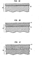
- FIGS. 1A-1F are pictorial representations (through cross sectional views) illustrating the basic processing steps of the present invention
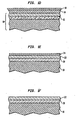
- FIGS. 2A-2C are pictorial representations (through cross sectional views) illustrating an alternative embodiment of the present invention
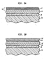
- FIGS. 3A-3B are pictorial representations (through cross sectional views) illustrating an alternative embodiment of the present invention.
- FIG. 4 is a cross-sectional SEM image of a SiGe-on-insulator material formed using the method of the present invention
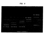
- FIG. 5 is a cross-sectional SEM image of a double-layered SiGe-on-insulator material formed by the method of the present invention.
- FIG. 6 is a cross-sectional SEM image of a SGOI substrate of the present invention.
- the present invention which provides a low-cost method for forming a substantially relaxed SiGe-on-insulator substrate material wherein wafer bonding and/or oxygen implantation are not employed, will now be described in greater detail by referring to the drawings that accompany the present application.
- like and/or corresponding elements are referred to by like reference numerals.
- FIGS. 1A-1F illustrate an embodiment of the present invention in which a substantially relaxed SiGe alloy layer is formed atop a continuous buried oxide that extends entirely across the surface of a wafer.
- FIG. 1A shows a structure during the initial stage of the present invention.
- the structure illustrated in FIG. 1A includes a Si-containing substrate 10 in which a hole-rich region 12 is formed in the Si-containing substrate 10.
- Si-containing substrate is used in the present invention to denote a semiconductor material that includes at least silicon.
- Si-containing materials include, but are not limited to: Si, SiGe, SiC, SiGeC, Si/Si, Si/SiC, Si/SiGeC, and preformed silicon-on-insulators (SOIs) or SiGe-on-insulators which may include any number of buried insulating (i.e., continuous, non-continuous or a combination of continuous and non-continuous) regions therein.
- SOIs silicon-on-insulators
- SiGe-on-insulators which may include any number of buried insulating (i.e., continuous, non-continuous or a combination of continuous and non-continuous) regions therein.
- the Si-containing substrate used in the present invention may be undoped or it may be an electron-rich or hole-rich Si-containing substrate.
- the hole-rich region 12 is a region that is more heavily doped than the surrounding Si-containing material.
- the hole-rich region contains a p-type dopant concentration of about 1E19 atoms/cm 3 or greater, with a p-type dopant concentration of from about 1 E20 to about 5E20 atoms/cm 3 being more preferred.
- the hole-rich region 12 can be formed by first growing a p-rich epitaxial layer on a surface of an initial Si-containing substrate and then growing a single crystal Si-containing layer having less doping than the p-rich epitaxial layer atop the previously grown layer.
- the p-rich epitaxial layer is grown using known epitaxial growth methods in which the dopant is included within the Si source gas.
- Examples of various epitaxial growth methods that may be used at this point of the present invention include, for example, low-pressure chemical vapor deposition (LPCVD), rapid thermal chemical vapor deposition (RTCVD), low-energy plasma, deposition (LEPD), ultra-high vacuum chemical vapor deposition (UHVCVD), atmospheric pressure chemical vapor deposition (APCVD), molecular beam epitaxy (MBE) and plasma-enhanced chemical vapor deposition (PECVD).
- LPCVD low-pressure chemical vapor deposition
- RTCVD rapid thermal chemical vapor deposition
- LEPD low-energy plasma, deposition
- UHVCVD ultra-high vacuum chemical vapor deposition
- APCVD atmospheric pressure chemical vapor deposition
- MBE molecular beam epitaxy
- PECVD plasma-enhanced chemical vapor deposition
- the thicknesses of the p-rich epitaxial layer and the single crystal Si-containing layer may vary depending on the final buried oxide thickness requirement in the SGOI or SOI layers.
- the p-rich epitaxial layer has a thickness of from about 5 to about 500 nm, with a thickness of from about 100 to about 200 nm being more highly preferred, while the single crystal Si-containing layer has a thickness of from about 50 to about 1000 nm, with a thickness of from about 100 to about 500 nm being more highly preferred.
- the p-rich epitaxial layer and the single crystal Si-containing layer may be grown in two different steps or a single step, without breaking vacuum, may be used in forming the p-rich epitaxial layer and the single crystal Si-containing layer.
- the single crystal Si-containing layer is located above the hole-rich region 12.
- the single crystal Si-containing layer may comprise the same or different Si material as the substrate 10.
- the structure shown in FIG. 1A is formed by ion implanting a p-type dopant into an initial single crystal Si-containing substrate such that the peak concentration of the p-type dopant is at some predetermined depth that is below the upper surface of the substrate.
- p-type doping is used herein to describe an element from Group III-A of the Periodic Table of Elements.
- Examples of p-type doping that can be employed in forming the hole-rich region include, but are not limited to: Ga, Al, B and BF 2 .
- B or BF 2 are particularly preferred in the present invention.
- boron with an energy of about 100 keV to 500 keV or BF 2 with an energy of about 500 keV to about 2500 keV and a dose of about 5E15 atoms/cm 2 to about 5E16 atoms/cm 2 can be used to form the hole-rich region 12.
- an optional annealing step may be performed to electrically activate B to create holes.
- the annealing used at this point of the present invention may include a furnace anneal, a rapid thermal anneal, or a spike anneal.
- the furnace anneal is typically carried out at a temperature of about 600°C or greater for a time period of about 15 minutes or greater.
- the furnace anneal is performed at a temperature of from about 650°C to about 800°C for a time period of from about 15 to about 250 minutes.
- the furnace anneal is typically performed in the presence of an inert gas atmosphere and/or an oxidizing ambient including, for example, He, Ar, O 2 , N 2 and mixtures thereof.
- the RTA is typically carried out at a temperature of about 800°C or greater for a time period of about 5 minutes or less.
- the RTA is performed at a temperature of from about 900°C to about 1050°C for a time period of from about 5 to about 30 seconds.
- the RTA is typically performed in the presence of an inert gas atmosphere and/or an oxidizing ambient including, for example, He, Ar, O 2 , N 2 and mixtures thereof.
- the spike anneal is typically performed at a temperature of about 900°C or greater for a time period of about 1 second or less. Preferably, the spike anneal is performed at a temperature of from about 900°C to about 1100°C.
- the spike anneal is typically performed in the presence of an inert gas atmosphere and/or an oxidizing ambient including, for example, He, Ar, O 2 , N 2 and mixtures thereof.
- Ge-containing layer 14 is then formed atop the upper surface of the Si-containing substrate 10, which includes the hole-rich region 12.
- the resultant structure including Ge-containing layer 14 is shown, for example, in FIG. 1B.
- the term "Ge-containing layer” denotes a pure Ge layer containing 100 atomic percent Ge or a SiGe alloy that includes up to 99.99 atomic percent Ge. When SiGe alloys are employed, it is preferred that the Ge content in the SiGe alloy be from about 0.1 to about 99.9 atomic percent, with a Ge atomic percent of from about 10 to about 35 atomic percent being more highly preferred.
- the Ge-containing layer 14 is formed atop the upper surface of Si-containing substrate 10 using any conventional epitaxial growth method that is known to those skilled in the art which is capable of (i) growing a thermodynamically stable (below a critical thickness) Ge-containing layer, (ii) growing a Ge-containing layer that is metastable and substantially free from defects, i.e., misfit and TD dislocations or (iii) growing a Ge-containing layer that is relaxed and with defects.
- any conventional epitaxial growth method that is known to those skilled in the art which is capable of (i) growing a thermodynamically stable (below a critical thickness) Ge-containing layer, (ii) growing a Ge-containing layer that is metastable and substantially free from defects, i.e., misfit and TD dislocations or (iii) growing a Ge-containing layer that is relaxed and with defects.
- Illustrative examples of such epitaxial growing processes that are capable of satisfy conditions (i), (ii) or (iii) include, but are not limited to: low-pressure chemical vapor deposition (LPCVD), rapid thermal chemical vapor deposition (RTCVD), low-energy plasma deposition (LEPD), ultra-high vacuum chemical vapor deposition (UHVCVD), atmospheric pressure chemical vapor deposition (APCVD), molecular beam epitaxy (MBE) and plasma-enhanced chemical vapor deposition (PECVD).
- LPCVD low-pressure chemical vapor deposition
- RTCVD rapid thermal chemical vapor deposition
- LEPD low-energy plasma deposition
- UHVCVD ultra-high vacuum chemical vapor deposition
- APCVD atmospheric pressure chemical vapor deposition
- MBE molecular beam epitaxy
- PECVD plasma-enhanced chemical vapor deposition
- the thickness of the Ge-containing layer 14 formed at this point of the present invention may vary, but typically Ge-containing layer 14 has a thickness of from about 10 to about 500 nm, with a thickness of from about 20 to about 200 nm being more highly preferred.
- the steps used in forming the structures shown in FIGS. 1A and 1B may be combined by epitaxially growing all of the layers in a single deposition step. Namely, epitaxial growth of the hole-rich region followed by growth of a single crystal Si layer and then growth of the Ge-containing layer.
- the hole-rich region 12 is introduced into the structure after the Ge-containing layer 14 has been formed atop a Si-containing substrate 10.
- the hole-rich region 12 is formed via ion implantation after formation of the Ge-containing layer 14 therefore obviating the need for two separate processing steps.
- one of the above mentioned annealing techniques is used to activate the dopants.
- FIG. 1B is subjected to an electrolytic anodization process that is capable of converting the hole-rich region 12 into a porous region 16.
- the resultant structure including porous region 16 that is formed after the anodization process is shown, for example, in FIG. 1C.
- the anodization process is performed by immersing the structure shown in FIG. 1 B into an HF-containing solution while an electrical bias is applied to the structure with respect to an electrode also placed in the HF-containing solution.
- the structure typically serves as the positive electrode of the electrochemical cell, while another semiconducting material such as Si, or a metal is employed as the negative electrode.
- the HF anodization converts p-doped single crystal Si into porous Si.
- the rate of formation and the nature of the porous Si so-formed is determined by both the material properties, i.e., doping type and concentration, as well as the reaction conditions of the anodization process itself (current density, bias, illumination and additives in the HF-containing solution).
- the porous Si forms with greatly increased efficiency in the higher doped regions and therefore, the buried hole-rich region 12 is converted into porous Si efficiently.
- the porous Si region 16 formed in the present invention has a porosity of about 0.1 % or higher.
- the depth of the porous Si region 16, as measured from the uppermost surface of the structure to the uppermost surface of the porous Si, is about 50 nm or greater.
- HF-containing solution includes concentrated HF (49%), a mixture of HF and water, a mixture of HF and a monohydric alcohol such as methanol, ethanol, propanol, etc, or HF mixed with at least one surfactant.
- the amount of surfactant that is present in the HF solution is typically from about 1 to about 50%, based on 49% HF.
- the anodization process which converts the hole-rich region 12 into a porous Si region 16, is performed using a constant current source that operates at a current density of from about 0.05 to about 50 milliAmps/cm 2 .
- a light source may be optionally used to illuminate the sample.
- the anodization process of the present invention is employed using a constant current source operating at a current density of from about 0.1 to about 5 milliAmps/cm 2 .
- the anodization process is typically performed at room temperature or at a temperature that is elevated from room temperature may be used. Following the anodization process, the structure is typically rinsed with deionized water and dried.
- an optional cap layer 18 is formed atop the Ge-containing layer 14 at this point of the present invention.
- the structure including the optional cap layer 18 is shown, for example, in FIG. 1D.
- the optional cap layer 18 employed in the present invention comprises any Si material including, for example, epitaxial Si (epi-Si), amorphous Si (a:Si), single or polycrystalline Si or any combination thereof. Of the various Si materials listed above, it is preferred that epi-Si be employed as the optional cap layer 18.
- the optional cap layer 18 has a thickness of from about 1 to about 100 nm, with a thickness of from about 1 to about 30 nm being more highly preferred.
- the optional cap layer 18 is formed using known deposition processes including one of the epitaxial growth processes mentioned above.
- the structure including the Ge-containing layer 14 and the thus formed porous Si region 16, with or without the optional cap layer 18, is then heated, i.e., annealed, at a temperature which permits interdiffusion of Ge mostly within the single crystal Si layer above the porous Si, thereby forming a substantially relaxed, single crystal SiGe layer 22, while simultaneously converting the porous Si region 16 into a buried oxide region 20.
- the resultant structure is shown, for example, in FIG. 1E. That is, the heating step forms a relaxed single crystal SiGe layer 22 atop a buried oxide layer 20. Note that an oxide layer 24 is formed atop layer 22 during the heating step.
- This surface oxide layer i.e., oxide layer 24, is typically, but not always, removed from the structure after the heating step using a conventional wet etch process wherein a chemical etchant such as HF that has a high selectivity for removing oxide as compared to SiGe is employed.
- a chemical etchant such as HF that has a high selectivity for removing oxide as compared to SiGe is employed.
- a second single crystal Si layer that is strained or unstrained depending on the relaxation of the SiGe layer can be formed atop layer 22 and the above processing steps of the present invention may be repeated any number of times to produce a multilayered relaxed SiGe substrate material.
- the measured strain of the second Si layer is typically from 0% to about 1.5%.
- the surface oxide layer 24 formed after the heating step of the present invention has a variable thickness which may range from about 10 to about 1000 nm, with a thickness of from about 20 to about 500 nm being more highly preferred.
- the heating step of the present invention is an annealing step which is performed at a temperature of from about 650° to about 1350°C, with a temperature of from about 1200° to about 1320°C being more highly preferred.
- the heating step of the present invention is carried out in an oxidizing ambient which includes at least one oxygen-containing gas such as O 2 , NO, N 2 O, ozone, air and other like oxygen-containing gases.
- the oxygen-containing gas may be admixed with each other (such as an admixture of O 2 and NO), or the gas may be diluted with an inert gas such as He, Ar, N 2 , Xe, Kr, or Ne.
- the diluted ambient contains from about 0.5 to about 100% of oxygen-containing gas, the remainder, up to 100%, being inert gas.
- the heating step may be carried out for a variable period of time that typically ranges from about 10 to about 1800 minutes, with a time period of from about 60 to about 600 minutes being more highly preferred.
- the heating step may be carried out at a single targeted temperature, or various ramp and soak cycles using various ramp rates and soak times can be employed.
- the heating step is performed under an oxidizing ambient to achieve the presence of oxide layers, i.e., layers 20 and 24, which act as diffusion barriers to Ge atoms. Note that the porous Si region reacts with diffused oxygen at an enhanced rate. Once the oxide layers (surface and buried oxide) are formed, Ge becomes trapped between the oxide layers. As the oxidation process continues and consumption of the Ge-containing layer and single crystal occurs, the ratio of Ge to Si in the alloy layer increases because the Ge is rejected from the oxide and Si is incorporated into the growing surface oxide layer.
- Efficient thermal mixing is achieved in the present invention when the heating step is carried out at a temperature of from about 1200° to about 1320°C in a diluted oxygen-containing gas.
- the role of the heating step of the present invention is (1) to allow Ge atoms to diffuse more quickly thereby maintaining a homogeneous distribution during annealing; (2) to subject the ('initially') strained layer structure to a thermal budget which will facilitate an equilibrium configuration, and (3) to convert the porous Si region into a thermal buried oxide region.
- the structure includes a uniform and substantially relaxed SiGe alloy layer, i.e., layer 22, sandwiched between the buried oxide layer 20 and surface oxide layer 24.
- substantially relaxed SiGe layer 22 has a thickness of about 2000 nm or less, with a thickness of from about 10 to about 100 nm being more highly preferred. Note that the substantially relaxed SiGe layer 22 formed in the present invention is thinner than prior art SiGe buffer layers and has a defect density including misfits and TDs, of less than about 10 8 defects/cm 2 .
- the buried oxide layer 20 formed during the heating step has a thickness of about 50 nm to about 500 nm, with a thickness of from about 100 to about 200 nm being more highly preferred.
- the buried oxide layer 20 has a smooth and continuous interface with the overlying substantially relaxed SiGe layer 22.
- the substantially relaxed SiGe layer 22 formed in the present invention has a final Ge content of from about 0.1 to about 99.9 atomic percent, with an atomic percent of Ge of from about 10 to about 35 being more highly preferred.
- Another characteristic feature of the substantially relaxed SiGe layer 22 is that it has a measured lattice relaxation of from about 1 to about 100 %, with a measured lattice relaxation of from about 50 to about 80 % being more highly preferred.
- the surface oxide layer 24 may be stripped at this point of the present invention so as to provide the SiGe-on-insulator substrate material shown, for example, in FIG. 1F.
- FIG. 2A shows an initial structure of this embodiment in which the Si-containing substrate 10 has discrete and isolated islands of hole-rich regions 12 formed therein.
- the discrete hole-rich regions 12 may be formed by using a masked ion implantation process or by growing a continuous hole-rich layer and subjecting the newly grown layer to lithography and etching. After the etching step, a single crystal Si layer is grown over the entire structure providing the structure shown in FIG. 2A.
- FIG. 2B shows the structure that is formed after Ge-containing layer 14 is formed on the surface of the structure shown in FIG. 2A.
- the Ge-containing layer 14 is formed utilizing one of the above mentioned epitaxial growth methods.
- hole-rich region 12 may be formed into substrate 10 after formation of Ge-containing layer 14 onto substrate 10.
- the structure shown in FIG. 2B including the Ge-containing 14 and hole-rich region 12 is subjected to the above described anodization process. As stated above, the anodization process forms porous Si regions 16 in the substrate in the hole-rich region.
- An optional cap layer, not shown, may then be formed atop the structure.
- the structure, with or without the optional cap layer, is then subjected to the above-described annealing step providing the structure shown, for example, in FIG. 2C.
- reference numerals 10, 20 and 22 have the same meaning as described above; the surface oxide layer 24 has been removed from this structure.
- FIGS. 3A-3B show another alternative embodiment of the present invention in which a double SGOI layer is formed in the same structure.
- the double SGOI layer is formed by first performing the steps described above in providing the structure shown in FIG. 1F. After providing the structure, a Si-containing layer 10' having a hole-rich region 12' is formed atop the structure and then a Ge-containing layer 14' is formed atop the Si-containing layer 10'. It is also possible to form layers 10' and 14' first and then form hole-rich region 12' into layer 10'.
- FIG. 3A provides an illustration of this structure. Next, the steps of anodization and annealing are repeated providing the structure shown, for example, in FIG. 3B. In FIG.
- a second buried oxide layer 20' is formed as well as a second substantially relaxed SiGe layer 22'.
- the same procedure can be repeated numerous times to provide a multi-SGOI layered structure.
- the multi-SGOI layers may all be continuous, be discontinuous or they may exist as a combination thereof.
- FIGS. 4 and 5 show actual SEM images of the substantially relaxed SiGe-on-insulator substrate materials produced using the method of the present invention.
- FIG. 4 is a cross-sectional SEM image of a SGOI substrate material formed by oxidation of a porous Si layer.
- the thin dark band labeled as H2 (107 nm) is the buried oxide layer.
- the layer above it, H3 (406) is the SiGe layer at 2 at. % Ge.
- the small voids within the layer are the attempted formation of a second buried oxide layer.
- the uppermost gray layer is the surface oxide.
- FIG. 5 is a cross-sectional SEM image of a double-layered SGOI substrate material formed by oxidation of porous Si.
- the thin dark band labeled as H1 (75 nm) is the first buried oxide layer.
- the layer above it, H2 (144 nm) is the first SiGe layer (0.2 at. % Ge).
- The,next dark band labeled as H3 (131 nm) is the second buried oxide layer and the next layer, H4 (140 nm) is the second SiGe layer (4.5 at. % ' Ge).
- the uppermost dark-gray layer is the surface oxide layer.
- FIG. 6 shows a SGOI structure obtained from similar substrates as shown in FIGS. 4 and 5 but after increased oxidation during high temperature anneal such that the top SGOI and BOX layers in FIGS. 4 and 5 are consumed by the increased oxidation.
- Increased oxidation can be accomplished either by increasing oxygen concentration in the anneal ambient compared to that used for annealing the structures shown in FIGS. 4 and 5, or by increasing anneal time with the same oxygen concentration as that used to create structures of FIGS. 4 and 5.
- FIG. 6 is a cross-sectional SEM image of a SGOI.
- the thin dark band labeled as H1 (123 nm) is the SGOI layer with an estimated 4.5% Ge.
- the thin dark band labeled as H2 (114 nm) is the BOX layer.
- the uppermost dark-gray layer is the surface oxide layer.
- a Si layer may be formed atop the SiGe layer using conventional epitaxial deposition process well-known to those skilled in the art.
- the thickness of the epi-Si layer may vary, but typically, the epi-Si layer has a thickness of from about 1 to about 100 nm.
- additional SiGe can be formed atop the relaxed SiGe layer utilizing the above mentioned processing steps and thereafter epi-Si may be formed. Because the relaxed SiGe layer has a large in-plane lattice parameter as compared to the epi-Si layer, the epi-Si layer will be strained in a tensile manner.
- the present invention also contemplates superlattice structures as well as lattice mismatched structures that include at least the SiGe-on-insulator substrate material of the present invention.
- superlattice structures such structures would include at least the substantially relaxed SiGe-on-insulator substrate material of the present invention, and alternating Si and SiGe layers formed atop the substrate material.
- GaAs, GaP or other like compounds would be formed atop the substantially relaxed SiGe-on-insulator substrate material of the present invention.
Landscapes
- Engineering & Computer Science (AREA)
- Physics & Mathematics (AREA)
- Chemical & Material Sciences (AREA)
- Condensed Matter Physics & Semiconductors (AREA)
- General Physics & Mathematics (AREA)
- Manufacturing & Machinery (AREA)
- Computer Hardware Design (AREA)
- Microelectronics & Electronic Packaging (AREA)
- Power Engineering (AREA)
- Thermal Sciences (AREA)
- Crystallography & Structural Chemistry (AREA)
- Materials Engineering (AREA)
- Mechanical Engineering (AREA)
- Metallurgy (AREA)
- Organic Chemistry (AREA)
- Recrystallisation Techniques (AREA)
- Element Separation (AREA)
- Local Oxidation Of Silicon (AREA)
- Silicates, Zeolites, And Molecular Sieves (AREA)
Applications Claiming Priority (2)
| Application Number | Priority Date | Filing Date | Title |
|---|---|---|---|
| US10/662,028 US7125458B2 (en) | 2003-09-12 | 2003-09-12 | Formation of a silicon germanium-on-insulator structure by oxidation of a buried porous silicon layer |
| PCT/US2004/029378 WO2005031810A2 (en) | 2003-09-12 | 2004-09-10 | Formation of a silicon germanium-on-insulator structure by oxidation of a buried porous silicon layer |
Publications (2)
| Publication Number | Publication Date |
|---|---|
| EP1665340A2 EP1665340A2 (en) | 2006-06-07 |
| EP1665340B1 true EP1665340B1 (en) | 2007-08-01 |
Family
ID=34274005
Family Applications (1)
| Application Number | Title | Priority Date | Filing Date |
|---|---|---|---|
| EP04809708A Expired - Lifetime EP1665340B1 (en) | 2003-09-12 | 2004-09-10 | Formation of a silicon germanium-on-insulator structure by oxidation of a buried porous silicon layer |
Country Status (9)
| Country | Link |
|---|---|
| US (1) | US7125458B2 (enExample) |
| EP (1) | EP1665340B1 (enExample) |
| JP (1) | JP4856544B2 (enExample) |
| KR (1) | KR100856988B1 (enExample) |
| CN (1) | CN100429761C (enExample) |
| AT (1) | ATE368939T1 (enExample) |
| DE (1) | DE602004007940T2 (enExample) |
| TW (1) | TWI330388B (enExample) |
| WO (1) | WO2005031810A2 (enExample) |
Families Citing this family (16)
| Publication number | Priority date | Publication date | Assignee | Title |
|---|---|---|---|---|
| US7566482B2 (en) * | 2003-09-30 | 2009-07-28 | International Business Machines Corporation | SOI by oxidation of porous silicon |
| US7172930B2 (en) * | 2004-07-02 | 2007-02-06 | International Business Machines Corporation | Strained silicon-on-insulator by anodization of a buried p+ silicon germanium layer |
| US7767541B2 (en) * | 2005-10-26 | 2010-08-03 | International Business Machines Corporation | Methods for forming germanium-on-insulator semiconductor structures using a porous layer and semiconductor structures formed by these methods |
| US7833884B2 (en) * | 2007-11-02 | 2010-11-16 | International Business Machines Corporation | Strained semiconductor-on-insulator by Si:C combined with porous process |
| US7772096B2 (en) * | 2008-07-10 | 2010-08-10 | International Machines Corporation | Formation of SOI by oxidation of silicon with engineered porosity gradient |
| FR2935194B1 (fr) * | 2008-08-22 | 2010-10-08 | Commissariat Energie Atomique | Procede de realisation de structures geoi localisees, obtenues par enrichissement en germanium |
| US8618554B2 (en) * | 2010-11-08 | 2013-12-31 | International Business Machines Corporation | Method to reduce ground-plane poisoning of extremely-thin SOI (ETSOI) layer with thin buried oxide |
| JP2014535124A (ja) | 2011-09-30 | 2014-12-25 | インテル コーポレイション | エネルギー貯蔵デバイスのエネルギー密度及び達成可能な電力出力を増やす方法 |
| US8518807B1 (en) | 2012-06-22 | 2013-08-27 | International Business Machines Corporation | Radiation hardened SOI structure and method of making same |
| US9087716B2 (en) * | 2013-07-15 | 2015-07-21 | Globalfoundries Inc. | Channel semiconductor alloy layer growth adjusted by impurity ion implantation |
| US9343303B2 (en) | 2014-03-20 | 2016-05-17 | Samsung Electronics Co., Ltd. | Methods of forming low-defect strain-relaxed layers on lattice-mismatched substrates and related semiconductor structures and devices |
| US10032870B2 (en) | 2015-03-12 | 2018-07-24 | Globalfoundries Inc. | Low defect III-V semiconductor template on porous silicon |
| US9899274B2 (en) | 2015-03-16 | 2018-02-20 | International Business Machines Corporation | Low-cost SOI FinFET technology |
| US10833175B2 (en) * | 2015-06-04 | 2020-11-10 | International Business Machines Corporation | Formation of dislocation-free SiGe finFET using porous silicon |
| US20190131454A1 (en) * | 2017-11-01 | 2019-05-02 | Qualcomm Incorporated | Semiconductor device with strained silicon layers on porous silicon |
| CN112908849A (zh) * | 2021-01-28 | 2021-06-04 | 上海华力集成电路制造有限公司 | 一种形成SiGe沟道的热处理方法 |
Family Cites Families (9)
| Publication number | Priority date | Publication date | Assignee | Title |
|---|---|---|---|---|
| US4104090A (en) * | 1977-02-24 | 1978-08-01 | International Business Machines Corporation | Total dielectric isolation utilizing a combination of reactive ion etching, anodic etching, and thermal oxidation |
| JPS5831730B2 (ja) * | 1979-10-15 | 1983-07-08 | 松下電器産業株式会社 | 半導体装置の製造方法 |
| JPS592185B2 (ja) * | 1980-02-04 | 1984-01-17 | 日本電信電話株式会社 | 半導体基体内への絶縁領域の形成法 |
| KR960002765B1 (ko) * | 1992-12-22 | 1996-02-26 | 금성일렉트론주식회사 | 절연체 위에 단결정 반도체 제조방법 |
| US6376859B1 (en) * | 1998-07-29 | 2002-04-23 | Texas Instruments Incorporated | Variable porosity porous silicon isolation |
| US5950094A (en) * | 1999-02-18 | 1999-09-07 | Taiwan Semiconductor Manufacturing Company, Ltd. | Method for fabricating fully dielectric isolated silicon (FDIS) |
| JP4212228B2 (ja) * | 1999-09-09 | 2009-01-21 | 株式会社東芝 | 半導体装置の製造方法 |
| JP2002305293A (ja) * | 2001-04-06 | 2002-10-18 | Canon Inc | 半導体部材の製造方法及び半導体装置の製造方法 |
| US6812116B2 (en) * | 2002-12-13 | 2004-11-02 | Taiwan Semiconductor Manufacturing Company, Ltd. | Method of fabricating a wafer with strained channel layers for increased electron and hole mobility for improving device performance |
-
2003
- 2003-09-12 US US10/662,028 patent/US7125458B2/en not_active Expired - Fee Related
-
2004
- 2004-09-01 TW TW093126414A patent/TWI330388B/zh not_active IP Right Cessation
- 2004-09-10 EP EP04809708A patent/EP1665340B1/en not_active Expired - Lifetime
- 2004-09-10 AT AT04809708T patent/ATE368939T1/de not_active IP Right Cessation
- 2004-09-10 CN CNB2004800263800A patent/CN100429761C/zh not_active Expired - Fee Related
- 2004-09-10 WO PCT/US2004/029378 patent/WO2005031810A2/en not_active Ceased
- 2004-09-10 JP JP2006526273A patent/JP4856544B2/ja not_active Expired - Fee Related
- 2004-09-10 DE DE602004007940T patent/DE602004007940T2/de not_active Expired - Lifetime
- 2004-09-10 KR KR1020067003316A patent/KR100856988B1/ko not_active Expired - Fee Related
Also Published As
| Publication number | Publication date |
|---|---|
| ATE368939T1 (de) | 2007-08-15 |
| WO2005031810A3 (en) | 2005-06-23 |
| DE602004007940T2 (de) | 2008-04-24 |
| TWI330388B (en) | 2010-09-11 |
| CN1957458A (zh) | 2007-05-02 |
| KR20060061839A (ko) | 2006-06-08 |
| WO2005031810A2 (en) | 2005-04-07 |
| JP4856544B2 (ja) | 2012-01-18 |
| CN100429761C (zh) | 2008-10-29 |
| US7125458B2 (en) | 2006-10-24 |
| TW200516666A (en) | 2005-05-16 |
| US20050056352A1 (en) | 2005-03-17 |
| DE602004007940D1 (de) | 2007-09-13 |
| JP2007505502A (ja) | 2007-03-08 |
| EP1665340A2 (en) | 2006-06-07 |
| KR100856988B1 (ko) | 2008-09-04 |
Similar Documents
| Publication | Publication Date | Title |
|---|---|---|
| US6805962B2 (en) | Method of creating high-quality relaxed SiGe-on-insulator for strained Si CMOS applications | |
| US6855436B2 (en) | Formation of silicon-germanium-on-insulator (SGOI) by an integral high temperature SIMOX-Ge interdiffusion anneal | |
| US7816664B2 (en) | Defect reduction by oxidation of silicon | |
| US7304328B2 (en) | Use of hydrogen implantation to improve material properties of silicon-germanium-on-insulator material made by thermal diffusion | |
| US7592671B2 (en) | Strained silicon-on-insulator by anodization of a buried p+ silicon germanium layer | |
| US6946373B2 (en) | Relaxed, low-defect SGOI for strained Si CMOS applications | |
| US7679141B2 (en) | High-quality SGOI by annealing near the alloy melting point | |
| EP1665340B1 (en) | Formation of a silicon germanium-on-insulator structure by oxidation of a buried porous silicon layer | |
| US20050221591A1 (en) | Method of forming high-quality relaxed SiGe alloy layers on bulk Si substrates | |
| US6989058B2 (en) | Use of thin SOI to inhibit relaxation of SiGe layers | |
| US7833884B2 (en) | Strained semiconductor-on-insulator by Si:C combined with porous process |
Legal Events
| Date | Code | Title | Description |
|---|---|---|---|
| PUAI | Public reference made under article 153(3) epc to a published international application that has entered the european phase |
Free format text: ORIGINAL CODE: 0009012 |
|
| 17P | Request for examination filed |
Effective date: 20060324 |
|
| AK | Designated contracting states |
Kind code of ref document: A2 Designated state(s): AT BE BG CH CY CZ DE DK EE ES FI FR GB GR HU IE IT LI LU MC NL PL PT RO SE SI SK TR |
|
| 17Q | First examination report despatched |
Effective date: 20060908 |
|
| DAX | Request for extension of the european patent (deleted) | ||
| GRAP | Despatch of communication of intention to grant a patent |
Free format text: ORIGINAL CODE: EPIDOSNIGR1 |
|
| RIC1 | Information provided on ipc code assigned before grant |
Ipc: H01L 21/762 20060101AFI20070215BHEP |
|
| GRAS | Grant fee paid |
Free format text: ORIGINAL CODE: EPIDOSNIGR3 |
|
| GRAA | (expected) grant |
Free format text: ORIGINAL CODE: 0009210 |
|
| AK | Designated contracting states |
Kind code of ref document: B1 Designated state(s): AT BE BG CH CY CZ DE DK EE ES FI FR GB GR HU IE IT LI LU MC NL PL PT RO SE SI SK TR |
|
| REG | Reference to a national code |
Ref country code: GB Ref legal event code: FG4D |
|
| REG | Reference to a national code |
Ref country code: CH Ref legal event code: EP |
|
| REG | Reference to a national code |
Ref country code: IE Ref legal event code: FG4D |
|
| REF | Corresponds to: |
Ref document number: 602004007940 Country of ref document: DE Date of ref document: 20070913 Kind code of ref document: P |
|
| ET | Fr: translation filed | ||
| PG25 | Lapsed in a contracting state [announced via postgrant information from national office to epo] |
Ref country code: BG Free format text: LAPSE BECAUSE OF FAILURE TO SUBMIT A TRANSLATION OF THE DESCRIPTION OR TO PAY THE FEE WITHIN THE PRESCRIBED TIME-LIMIT Effective date: 20071101 Ref country code: FI Free format text: LAPSE BECAUSE OF FAILURE TO SUBMIT A TRANSLATION OF THE DESCRIPTION OR TO PAY THE FEE WITHIN THE PRESCRIBED TIME-LIMIT Effective date: 20070801 Ref country code: ES Free format text: LAPSE BECAUSE OF FAILURE TO SUBMIT A TRANSLATION OF THE DESCRIPTION OR TO PAY THE FEE WITHIN THE PRESCRIBED TIME-LIMIT Effective date: 20071112 Ref country code: NL Free format text: LAPSE BECAUSE OF FAILURE TO SUBMIT A TRANSLATION OF THE DESCRIPTION OR TO PAY THE FEE WITHIN THE PRESCRIBED TIME-LIMIT Effective date: 20070801 |
|
| NLV1 | Nl: lapsed or annulled due to failure to fulfill the requirements of art. 29p and 29m of the patents act | ||
| REG | Reference to a national code |
Ref country code: CH Ref legal event code: PL |
|
| PG25 | Lapsed in a contracting state [announced via postgrant information from national office to epo] |
Ref country code: LI Free format text: LAPSE BECAUSE OF FAILURE TO SUBMIT A TRANSLATION OF THE DESCRIPTION OR TO PAY THE FEE WITHIN THE PRESCRIBED TIME-LIMIT Effective date: 20070801 Ref country code: AT Free format text: LAPSE BECAUSE OF FAILURE TO SUBMIT A TRANSLATION OF THE DESCRIPTION OR TO PAY THE FEE WITHIN THE PRESCRIBED TIME-LIMIT Effective date: 20070801 Ref country code: CH Free format text: LAPSE BECAUSE OF FAILURE TO SUBMIT A TRANSLATION OF THE DESCRIPTION OR TO PAY THE FEE WITHIN THE PRESCRIBED TIME-LIMIT Effective date: 20070801 Ref country code: PL Free format text: LAPSE BECAUSE OF FAILURE TO SUBMIT A TRANSLATION OF THE DESCRIPTION OR TO PAY THE FEE WITHIN THE PRESCRIBED TIME-LIMIT Effective date: 20070801 |
|
| PG25 | Lapsed in a contracting state [announced via postgrant information from national office to epo] |
Ref country code: BE Free format text: LAPSE BECAUSE OF FAILURE TO SUBMIT A TRANSLATION OF THE DESCRIPTION OR TO PAY THE FEE WITHIN THE PRESCRIBED TIME-LIMIT Effective date: 20070801 |
|
| PG25 | Lapsed in a contracting state [announced via postgrant information from national office to epo] |
Ref country code: MC Free format text: LAPSE BECAUSE OF NON-PAYMENT OF DUE FEES Effective date: 20070930 Ref country code: GR Free format text: LAPSE BECAUSE OF FAILURE TO SUBMIT A TRANSLATION OF THE DESCRIPTION OR TO PAY THE FEE WITHIN THE PRESCRIBED TIME-LIMIT Effective date: 20071102 Ref country code: DK Free format text: LAPSE BECAUSE OF FAILURE TO SUBMIT A TRANSLATION OF THE DESCRIPTION OR TO PAY THE FEE WITHIN THE PRESCRIBED TIME-LIMIT Effective date: 20070801 |
|
| PG25 | Lapsed in a contracting state [announced via postgrant information from national office to epo] |
Ref country code: SK Free format text: LAPSE BECAUSE OF FAILURE TO SUBMIT A TRANSLATION OF THE DESCRIPTION OR TO PAY THE FEE WITHIN THE PRESCRIBED TIME-LIMIT Effective date: 20070801 Ref country code: PT Free format text: LAPSE BECAUSE OF FAILURE TO SUBMIT A TRANSLATION OF THE DESCRIPTION OR TO PAY THE FEE WITHIN THE PRESCRIBED TIME-LIMIT Effective date: 20080102 Ref country code: CZ Free format text: LAPSE BECAUSE OF FAILURE TO SUBMIT A TRANSLATION OF THE DESCRIPTION OR TO PAY THE FEE WITHIN THE PRESCRIBED TIME-LIMIT Effective date: 20070801 |
|
| PLBE | No opposition filed within time limit |
Free format text: ORIGINAL CODE: 0009261 |
|
| STAA | Information on the status of an ep patent application or granted ep patent |
Free format text: STATUS: NO OPPOSITION FILED WITHIN TIME LIMIT |
|
| PG25 | Lapsed in a contracting state [announced via postgrant information from national office to epo] |
Ref country code: RO Free format text: LAPSE BECAUSE OF FAILURE TO SUBMIT A TRANSLATION OF THE DESCRIPTION OR TO PAY THE FEE WITHIN THE PRESCRIBED TIME-LIMIT Effective date: 20070801 Ref country code: SE Free format text: LAPSE BECAUSE OF FAILURE TO SUBMIT A TRANSLATION OF THE DESCRIPTION OR TO PAY THE FEE WITHIN THE PRESCRIBED TIME-LIMIT Effective date: 20071101 |
|
| 26N | No opposition filed |
Effective date: 20080506 |
|
| REG | Reference to a national code |
Ref country code: GB Ref legal event code: 746 Effective date: 20080808 |
|
| PG25 | Lapsed in a contracting state [announced via postgrant information from national office to epo] |
Ref country code: IE Free format text: LAPSE BECAUSE OF NON-PAYMENT OF DUE FEES Effective date: 20070910 |
|
| PG25 | Lapsed in a contracting state [announced via postgrant information from national office to epo] |
Ref country code: EE Free format text: LAPSE BECAUSE OF FAILURE TO SUBMIT A TRANSLATION OF THE DESCRIPTION OR TO PAY THE FEE WITHIN THE PRESCRIBED TIME-LIMIT Effective date: 20070801 |
|
| PG25 | Lapsed in a contracting state [announced via postgrant information from national office to epo] |
Ref country code: SI Free format text: LAPSE BECAUSE OF FAILURE TO SUBMIT A TRANSLATION OF THE DESCRIPTION OR TO PAY THE FEE WITHIN THE PRESCRIBED TIME-LIMIT Effective date: 20070801 |
|
| PG25 | Lapsed in a contracting state [announced via postgrant information from national office to epo] |
Ref country code: CY Free format text: LAPSE BECAUSE OF FAILURE TO SUBMIT A TRANSLATION OF THE DESCRIPTION OR TO PAY THE FEE WITHIN THE PRESCRIBED TIME-LIMIT Effective date: 20070801 |
|
| PG25 | Lapsed in a contracting state [announced via postgrant information from national office to epo] |
Ref country code: LU Free format text: LAPSE BECAUSE OF NON-PAYMENT OF DUE FEES Effective date: 20070910 |
|
| PG25 | Lapsed in a contracting state [announced via postgrant information from national office to epo] |
Ref country code: TR Free format text: LAPSE BECAUSE OF FAILURE TO SUBMIT A TRANSLATION OF THE DESCRIPTION OR TO PAY THE FEE WITHIN THE PRESCRIBED TIME-LIMIT Effective date: 20070801 Ref country code: HU Free format text: LAPSE BECAUSE OF FAILURE TO SUBMIT A TRANSLATION OF THE DESCRIPTION OR TO PAY THE FEE WITHIN THE PRESCRIBED TIME-LIMIT Effective date: 20080202 |
|
| PGFP | Annual fee paid to national office [announced via postgrant information from national office to epo] |
Ref country code: FR Payment date: 20100923 Year of fee payment: 7 |
|
| PGFP | Annual fee paid to national office [announced via postgrant information from national office to epo] |
Ref country code: GB Payment date: 20100923 Year of fee payment: 7 |
|
| PG25 | Lapsed in a contracting state [announced via postgrant information from national office to epo] |
Ref country code: IT Free format text: LAPSE BECAUSE OF NON-PAYMENT OF DUE FEES Effective date: 20070930 |
|
| PGFP | Annual fee paid to national office [announced via postgrant information from national office to epo] |
Ref country code: DE Payment date: 20100927 Year of fee payment: 7 |
|
| GBPC | Gb: european patent ceased through non-payment of renewal fee |
Effective date: 20110910 |
|
| REG | Reference to a national code |
Ref country code: FR Ref legal event code: ST Effective date: 20120531 |
|
| PG25 | Lapsed in a contracting state [announced via postgrant information from national office to epo] |
Ref country code: DE Free format text: LAPSE BECAUSE OF NON-PAYMENT OF DUE FEES Effective date: 20120403 |
|
| REG | Reference to a national code |
Ref country code: DE Ref legal event code: R119 Ref document number: 602004007940 Country of ref document: DE Effective date: 20120403 |
|
| PG25 | Lapsed in a contracting state [announced via postgrant information from national office to epo] |
Ref country code: FR Free format text: LAPSE BECAUSE OF NON-PAYMENT OF DUE FEES Effective date: 20110930 Ref country code: GB Free format text: LAPSE BECAUSE OF NON-PAYMENT OF DUE FEES Effective date: 20110910 |