EP1664573B1 - Azimutbremse fuer windkraftanlagen - Google Patents
Azimutbremse fuer windkraftanlagen Download PDFInfo
- Publication number
- EP1664573B1 EP1664573B1 EP04764722A EP04764722A EP1664573B1 EP 1664573 B1 EP1664573 B1 EP 1664573B1 EP 04764722 A EP04764722 A EP 04764722A EP 04764722 A EP04764722 A EP 04764722A EP 1664573 B1 EP1664573 B1 EP 1664573B1
- Authority
- EP
- European Patent Office
- Prior art keywords
- brake
- azimuth
- drive
- lever
- levers
- Prior art date
- Legal status (The legal status is an assumption and is not a legal conclusion. Google has not performed a legal analysis and makes no representation as to the accuracy of the status listed.)
- Expired - Lifetime
Links
Images
Classifications
-
- F—MECHANICAL ENGINEERING; LIGHTING; HEATING; WEAPONS; BLASTING
- F03—MACHINES OR ENGINES FOR LIQUIDS; WIND, SPRING, OR WEIGHT MOTORS; PRODUCING MECHANICAL POWER OR A REACTIVE PROPULSIVE THRUST, NOT OTHERWISE PROVIDED FOR
- F03D—WIND MOTORS
- F03D7/00—Controlling wind motors
- F03D7/02—Controlling wind motors the wind motors having rotation axis substantially parallel to the air flow entering the rotor
- F03D7/0204—Controlling wind motors the wind motors having rotation axis substantially parallel to the air flow entering the rotor for orientation in relation to wind direction
-
- F—MECHANICAL ENGINEERING; LIGHTING; HEATING; WEAPONS; BLASTING
- F03—MACHINES OR ENGINES FOR LIQUIDS; WIND, SPRING, OR WEIGHT MOTORS; PRODUCING MECHANICAL POWER OR A REACTIVE PROPULSIVE THRUST, NOT OTHERWISE PROVIDED FOR
- F03D—WIND MOTORS
- F03D7/00—Controlling wind motors
- F03D7/02—Controlling wind motors the wind motors having rotation axis substantially parallel to the air flow entering the rotor
- F03D7/0244—Controlling wind motors the wind motors having rotation axis substantially parallel to the air flow entering the rotor for braking
-
- F—MECHANICAL ENGINEERING; LIGHTING; HEATING; WEAPONS; BLASTING
- F16—ENGINEERING ELEMENTS AND UNITS; GENERAL MEASURES FOR PRODUCING AND MAINTAINING EFFECTIVE FUNCTIONING OF MACHINES OR INSTALLATIONS; THERMAL INSULATION IN GENERAL
- F16D—COUPLINGS FOR TRANSMITTING ROTATION; CLUTCHES; BRAKES
- F16D65/00—Parts or details
- F16D65/14—Actuating mechanisms for brakes; Means for initiating operation at a predetermined position
- F16D65/16—Actuating mechanisms for brakes; Means for initiating operation at a predetermined position arranged in or on the brake
- F16D65/18—Actuating mechanisms for brakes; Means for initiating operation at a predetermined position arranged in or on the brake adapted for drawing members together, e.g. for disc brakes
-
- F—MECHANICAL ENGINEERING; LIGHTING; HEATING; WEAPONS; BLASTING
- F05—INDEXING SCHEMES RELATING TO ENGINES OR PUMPS IN VARIOUS SUBCLASSES OF CLASSES F01-F04
- F05B—INDEXING SCHEME RELATING TO WIND, SPRING, WEIGHT, INERTIA OR LIKE MOTORS, TO MACHINES OR ENGINES FOR LIQUIDS COVERED BY SUBCLASSES F03B, F03D AND F03G
- F05B2260/00—Function
- F05B2260/90—Braking
- F05B2260/902—Braking using frictional mechanical forces
-
- F—MECHANICAL ENGINEERING; LIGHTING; HEATING; WEAPONS; BLASTING
- F16—ENGINEERING ELEMENTS AND UNITS; GENERAL MEASURES FOR PRODUCING AND MAINTAINING EFFECTIVE FUNCTIONING OF MACHINES OR INSTALLATIONS; THERMAL INSULATION IN GENERAL
- F16D—COUPLINGS FOR TRANSMITTING ROTATION; CLUTCHES; BRAKES
- F16D2121/00—Type of actuator operation force
- F16D2121/18—Electric or magnetic
- F16D2121/24—Electric or magnetic using motors
-
- F—MECHANICAL ENGINEERING; LIGHTING; HEATING; WEAPONS; BLASTING
- F16—ENGINEERING ELEMENTS AND UNITS; GENERAL MEASURES FOR PRODUCING AND MAINTAINING EFFECTIVE FUNCTIONING OF MACHINES OR INSTALLATIONS; THERMAL INSULATION IN GENERAL
- F16D—COUPLINGS FOR TRANSMITTING ROTATION; CLUTCHES; BRAKES
- F16D2125/00—Components of actuators
- F16D2125/18—Mechanical mechanisms
- F16D2125/20—Mechanical mechanisms converting rotation to linear movement or vice versa
- F16D2125/34—Mechanical mechanisms converting rotation to linear movement or vice versa acting in the direction of the axis of rotation
- F16D2125/40—Screw-and-nut
-
- F—MECHANICAL ENGINEERING; LIGHTING; HEATING; WEAPONS; BLASTING
- F16—ENGINEERING ELEMENTS AND UNITS; GENERAL MEASURES FOR PRODUCING AND MAINTAINING EFFECTIVE FUNCTIONING OF MACHINES OR INSTALLATIONS; THERMAL INSULATION IN GENERAL
- F16D—COUPLINGS FOR TRANSMITTING ROTATION; CLUTCHES; BRAKES
- F16D2125/00—Components of actuators
- F16D2125/18—Mechanical mechanisms
- F16D2125/58—Mechanical mechanisms transmitting linear movement
- F16D2125/64—Levers
-
- Y—GENERAL TAGGING OF NEW TECHNOLOGICAL DEVELOPMENTS; GENERAL TAGGING OF CROSS-SECTIONAL TECHNOLOGIES SPANNING OVER SEVERAL SECTIONS OF THE IPC; TECHNICAL SUBJECTS COVERED BY FORMER USPC CROSS-REFERENCE ART COLLECTIONS [XRACs] AND DIGESTS
- Y02—TECHNOLOGIES OR APPLICATIONS FOR MITIGATION OR ADAPTATION AGAINST CLIMATE CHANGE
- Y02E—REDUCTION OF GREENHOUSE GAS [GHG] EMISSIONS, RELATED TO ENERGY GENERATION, TRANSMISSION OR DISTRIBUTION
- Y02E10/00—Energy generation through renewable energy sources
- Y02E10/70—Wind energy
- Y02E10/72—Wind turbines with rotation axis in wind direction
Definitions
- the invention relates to an Anzimutbremse for wind turbines, with at least two arranged on a common brake disc brake shoe pairs, each associated with an actuator.
- Wind turbines have a nacelle which carries the impeller and which is rotatable about a vertical axis, so that the impeller can be directed into the wind.
- the azimuth brake serves to fix the nacelle in its respective azimuthal position and / or to dampen the rotational movement of the nacelle.
- the azimuth brake has a horizontal annular brake disc on which a plurality of pairs of brake shoes, for example 4 to 24 pairs of brake shoes are arranged, so that a sufficiently high holding force can be exerted on the brake disc.
- the Bremsbakkencrukencrue be hydraulically operated.
- a brake for the impeller of a wind turbine which can be actuated electromechanically.
- the actuator of this brake has a lever which is pivotable about an axis perpendicular to the plane of the brake disc, and a transmission for implementing the pivotal movement of this lever in an axial pressing movement of the brake shoes against the brake disc.
- a drive engages on the lever, which is preferably an electromechanical drive, for example a motor with a spindle drive. Due to the lever arm of the lever and the power transmission in the gearbox, a high pressure force of the brake shoes is achieved.
- the object of the invention is to provide an azimuth brake of the type mentioned, which is characterized by a simple structure.
- each actuator is a lever which is pivotable about an axis perpendicular to the plane of the brake disc axis, and a transmission for implementing the pivotal movement of the lever in an axial Andschreibterrorism having the brake shoes against the brake disc and that the levers of the at least two actuators are coupled by a common drive.
- the drive can be coupled with the two levers so that the levers are pivoted in opposite directions.
- Each lever can also serve as an abutment for the drive for adjusting the lever of the other actuator.
- levers can also be pivoted in the same direction.
- the levers may also be designed as toothed segments, which mesh with a common gear of the drive. If this gear is arranged as a central wheel, more than two or even all brake shoe pairs can be actuated by a common drive.
- the two brake shoes of each pair are mounted in a saddle, which is rigidly mounted on the circumference of the annular brake disc, preferably on the inner circumference, and in which the transmission is integrated.
- the levers of the two actuators which are assigned to a common drive, are preferably in the same direction from their respective saddles and have, for example, with respect to the brake disc approximately radially inward.
- the common drive which pulls the free ends of the lever together or pushes apart, the two levers are thus pivoted in opposite directions.
- the two gears are mirror images, so that the pivotal movement of the lever is implemented in both cases in a pressing movement of the brake shoes.
- the two levers protrude in opposite directions from their saddles, for example, one inwards and the other outwards, so that the levers are pivoted in the same direction of rotation when their free ends zusammmengenzogen by the common drive or pressed apart.
- the two gears can be the same design, for example as a spindle gear or ball screw with right-hand thread.
- each actuator has a spring assembly which biases the brake shoes against the brake disc, while the lever and the transmission are adapted to release the brake shoes against the force of the spring assembly of the brake disc. This design ensures fail-safety of the brake.
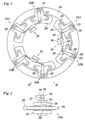
- FIG. 1 brake shown has an annular brake disk 10, which in a known manner, not shown here, rigid with the rotatable nacelle of a Wind turbine is connected and at the example in the example six Bremsbakkenpase 12A, 12B, 14A, 14B and 16A, 16B attack.
- Each brake shoe pair has a saddle 18, which is held by means of a holder 20 in the direction of rotation of the brake disc 10 fixed to a not shown, rigidly connected to the mast of the wind turbine component.
- the reverse arrangement is conceivable in which the brake disc 10 is held stationary on the mast and the brackets 20 are rotatable with the nacelle.
- Each saddle 18 has a transmission housing 22 which has a gear 24 (FIG. FIG. 2 ) receives to implement a rotary motion in a linear motion.
- the gear 24 which may be, for example, a spindle gear, a ball screw or a spindle with planetary roller
- two brake shoes 26 of the respective pair of brake shoes are employed from opposite sides against the brake disc 10 to exert a braking force on the brake disc.
- the transmission 24 has a central input shaft 28 which projects out of the transmission housing 22 and from which a lever 30 projects radially inwardly with respect to the brake disk 10.
- the levers 30 of two pairs of brake shoes are coupled together by a common electromechanical drive 32.
- the drive 32 is formed in the example shown by a spindle drive 34 with associated electric motor 36. From the spindle drive 34 go from two push rods 38, which are each hingedly connected to the free end of the lever 30.
- the spindle drive 36 is driven by the electric motor 36, the push rods 38 are pulled back in opposite directions, so that the associated levers 30 are pivoted in opposite directions of rotation.
- the two associated gear 24 are mirror images, so that the pivotal movement of the lever 30 causes in both cases that the brake shoes 26 are clamped axially against the brake disk 10. To this In each case with the help of a single drive 32 two associated brake shoe pairs 12A and 12B, 14A and 14B, 16A and 16B are operated simultaneously.
- the saddles 18 of the pair of brake shoes which are coupled by a common drive 32, are fastened in the example shown by means of bolts on a common bracket 20.
- the saddles 18 are formed as floating calipers. However, it is also a construction with fixed calipers possible with arranged on both sides of the brake disc 10 actuators, each one of the brake shoes 26 actuate. The levers of these actuators can again be coupled to a common drive.
Landscapes
- Engineering & Computer Science (AREA)
- General Engineering & Computer Science (AREA)
- Mechanical Engineering (AREA)
- Sustainable Energy (AREA)
- Chemical & Material Sciences (AREA)
- Combustion & Propulsion (AREA)
- Life Sciences & Earth Sciences (AREA)
- Sustainable Development (AREA)
- Braking Arrangements (AREA)
- Wind Motors (AREA)
- Nitrogen And Oxygen Or Sulfur-Condensed Heterocyclic Ring Systems (AREA)
- Supports For Plants (AREA)
- Nitrogen Condensed Heterocyclic Rings (AREA)
Priority Applications (1)
| Application Number | Priority Date | Filing Date | Title |
|---|---|---|---|
| PL04764722T PL1664573T3 (pl) | 2003-09-23 | 2004-09-02 | Hamulec azymutowy dla siłowni wiatrowych |
Applications Claiming Priority (2)
| Application Number | Priority Date | Filing Date | Title |
|---|---|---|---|
| DE20314822U DE20314822U1 (de) | 2003-09-23 | 2003-09-23 | Azimutbremse für Windkraftanlagen |
| PCT/EP2004/009763 WO2005038286A1 (de) | 2003-09-23 | 2004-09-02 | Azimutbremse für windkraftanlagen |
Publications (2)
| Publication Number | Publication Date |
|---|---|
| EP1664573A1 EP1664573A1 (de) | 2006-06-07 |
| EP1664573B1 true EP1664573B1 (de) | 2008-11-12 |
Family
ID=34178077
Family Applications (1)
| Application Number | Title | Priority Date | Filing Date |
|---|---|---|---|
| EP04764722A Expired - Lifetime EP1664573B1 (de) | 2003-09-23 | 2004-09-02 | Azimutbremse fuer windkraftanlagen |
Country Status (11)
| Country | Link |
|---|---|
| US (1) | US7398867B2 (pl) |
| EP (1) | EP1664573B1 (pl) |
| JP (1) | JP4565661B2 (pl) |
| CN (1) | CN100390435C (pl) |
| AT (1) | ATE414231T1 (pl) |
| BR (1) | BRPI0414684B1 (pl) |
| DE (2) | DE20314822U1 (pl) |
| DK (1) | DK1664573T3 (pl) |
| ES (1) | ES2317026T3 (pl) |
| PL (1) | PL1664573T3 (pl) |
| WO (1) | WO2005038286A1 (pl) |
Cited By (2)
| Publication number | Priority date | Publication date | Assignee | Title |
|---|---|---|---|---|
| DE102009026133A1 (de) | 2009-07-07 | 2011-01-20 | Emb Systems Ag | Bremsanordnung für eine Windkraftanlage |
| DE102009026131B3 (de) * | 2009-07-07 | 2011-02-10 | Emb Systems Ag | Bremsanordnung an einer Windkraftanlage |
Families Citing this family (20)
| Publication number | Priority date | Publication date | Assignee | Title |
|---|---|---|---|---|
| US7228945B2 (en) * | 2005-03-16 | 2007-06-12 | Hr Textron, Inc. | Techniques for employing electric brakes to control movement of rotatable components |
| DE102006024023B4 (de) * | 2006-05-23 | 2012-11-15 | Suzlon Energy Gmbh | Azimutbremse für Windkraftanlagen |
| US20090250939A1 (en) * | 2008-04-08 | 2009-10-08 | Curme Oliver D | Wind-driven generation of power |
| US20100038191A1 (en) * | 2008-08-15 | 2010-02-18 | Culbertson Michael O | Modular actuator for wind turbine brake |
| US20100038192A1 (en) * | 2008-08-15 | 2010-02-18 | Culbertson Michael O | Floating yaw brake for wind turbine |
| CN101576057B (zh) * | 2008-12-18 | 2011-04-20 | 上海电气液压气动有限公司 | 风力发电设备的安全制动系统 |
| DE102009009017B4 (de) * | 2009-02-16 | 2011-03-31 | Suzlon Energy Gmbh | Bremssystem für eine Windturbine |
| DE102009032873A1 (de) * | 2009-07-13 | 2011-01-20 | Pintsch Bubenzer Gmbh | Bremseinrichtung für Windenergieanlage |
| ES2385637T3 (es) | 2010-01-14 | 2012-07-27 | Nordex Energy Gmbh | Instalación de energía eólica con un sistema azimutal, así como procedimiento para el ajuste azimutal de una instalación de energía eólica |
| CN101915210B (zh) * | 2010-07-26 | 2012-02-08 | 林琪 | 风力发电机的风力驱动装置 |
| US20130149148A1 (en) * | 2011-12-09 | 2013-06-13 | Continental Wind Power, Inc. | Cable tension brake system |
| DE102012101484A1 (de) * | 2012-02-24 | 2013-08-29 | Setec Gmbh | Verfahren und Einrichtung zur Abbremsung einer Windenergieanlage in einem Notfall |
| KR101509976B1 (ko) * | 2013-11-20 | 2015-04-07 | 현대자동차주식회사 | 전동식 멀티 패드 브레이크 |
| TWD172384S (zh) * | 2015-03-17 | 2015-12-11 | 溫芫鋐 | 刹車碟盤之部分 |
| USD787995S1 (en) * | 2016-04-21 | 2017-05-30 | GRIMECA S.r.l. | Disc brake |
| DK179407B1 (en) * | 2016-06-17 | 2018-06-06 | Envision Energy Denmark Aps | Wind turbine with a yawing system and a method thereof |
| DE102016116945A1 (de) * | 2016-09-09 | 2018-03-15 | Wobben Properties Gmbh | Rotorarretiervorrichtung für eine Windenergieanlage und Verfahren |
| US10655600B2 (en) | 2017-11-08 | 2020-05-19 | General Electric Company | Bi-directional clutch for wind turbine yaw locking system |
| CN113915081B (zh) * | 2021-10-21 | 2023-05-23 | 中国华能集团清洁能源技术研究院有限公司 | 风力发电机用风轮锁定装置 |
| WO2025202084A1 (de) | 2024-03-27 | 2025-10-02 | Fm Energie Gmbh & Co.Kg | Bremszange und scheibenbremse mit hydraulisch-elastischen bremskolben |
Family Cites Families (19)
| Publication number | Priority date | Publication date | Assignee | Title |
|---|---|---|---|---|
| US1858973A (en) * | 1928-02-24 | 1932-05-17 | John G Steele | Vehicle brake |
| US2325596A (en) * | 1938-07-25 | 1943-08-03 | Edwin R Evans | Disk brake |
| US2616540A (en) * | 1948-12-29 | 1952-11-04 | Dana Corp | Automatic wear compensator for friction clutches |
| US2768710A (en) * | 1952-06-21 | 1956-10-30 | Dunlop Rubber Co | Disc type brake for vehicles |
| US3024873A (en) * | 1960-08-19 | 1962-03-13 | Thomas J Pierson | Disk brake |
| US4068131A (en) * | 1975-10-20 | 1978-01-10 | Jacobs Marcellus L | Wind electric plant |
| GB2004607B (en) * | 1977-09-21 | 1982-01-13 | Northern Eng Ind | Brake |
| DE3013862A1 (de) * | 1980-04-10 | 1981-10-15 | Alfred Teves Gmbh, 6000 Frankfurt | Teilbelagscheibenbremse mit einer druckplatte zwischen bremsbackenbeaufschlagungsglied und bremsbacken |
| US4483204A (en) * | 1982-12-27 | 1984-11-20 | Warsaw Arthur J | Prony brake dynamometer |
| US4513839A (en) * | 1983-05-06 | 1985-04-30 | Yale Materials Handling Corporation | Disc brake arrangement for steering and traction unit |
| DE3516821A1 (de) | 1985-05-10 | 1986-11-13 | Horst 2341 Brodersby Frees | Windkraftmaschine |
| DE4305285C1 (de) | 1993-02-20 | 1994-06-23 | Bubenzer Gerhard Bremsen | Teilbelag-Scheibenbremse zum Einbau in Antriebe in Industrieanlagen, Seilbahnantriebe und dgl. |
| US5660250A (en) * | 1993-02-20 | 1997-08-26 | Bubenzer Bremsen Gerhard Bubenzer Ing. Gmbh | Partially lined disc brake for installation in heavy-duty drives of industrial plants, ropeway drives, and cranes |
| DE10031472C1 (de) * | 2000-06-28 | 2002-04-18 | Tacke Windenergie Gmbh | Vorrichtung zur Arretierung einer von einem Rotor angetriebenen Welle einer Windkraftanlage |
| JP2002206576A (ja) * | 2001-01-12 | 2002-07-26 | Nissin Kogyo Co Ltd | 機械式車両用ディスクブレーキ |
| JP2002303255A (ja) * | 2001-04-09 | 2002-10-18 | Mitsubishi Heavy Ind Ltd | 風力発電装置 |
| JP4657534B2 (ja) * | 2001-09-17 | 2011-03-23 | 古河機械金属株式会社 | 風力発電機の電気ブレーキ |
| ATE432552T1 (de) * | 2002-03-08 | 2009-06-15 | Lawrence P Zepp | Bürstenloser permanentmagnetmotor oder drehstromgenerator mit variabler rotor- / statorausrichtung zur vergrösserung des geschwindigkeitsbereiches |
| DE20203794U1 (de) * | 2002-03-08 | 2003-07-31 | Hanning Elektro-Werke GmbH & Co. KG, Oerlinghausen, 33813 Oerlinghausen | Bremse, insbesondere für Windkraftanlagen |
-
2003
- 2003-09-23 DE DE20314822U patent/DE20314822U1/de not_active Expired - Lifetime
-
2004
- 2004-09-02 AT AT04764722T patent/ATE414231T1/de not_active IP Right Cessation
- 2004-09-02 ES ES04764722T patent/ES2317026T3/es not_active Expired - Lifetime
- 2004-09-02 PL PL04764722T patent/PL1664573T3/pl unknown
- 2004-09-02 DE DE502004008453T patent/DE502004008453D1/de not_active Expired - Lifetime
- 2004-09-02 US US10/572,789 patent/US7398867B2/en not_active Expired - Fee Related
- 2004-09-02 JP JP2006526543A patent/JP4565661B2/ja not_active Expired - Fee Related
- 2004-09-02 DK DK04764722T patent/DK1664573T3/da active
- 2004-09-02 EP EP04764722A patent/EP1664573B1/de not_active Expired - Lifetime
- 2004-09-02 CN CNB2004800259186A patent/CN100390435C/zh not_active Expired - Fee Related
- 2004-09-02 WO PCT/EP2004/009763 patent/WO2005038286A1/de not_active Ceased
- 2004-09-02 BR BRPI0414684A patent/BRPI0414684B1/pt not_active IP Right Cessation
Cited By (3)
| Publication number | Priority date | Publication date | Assignee | Title |
|---|---|---|---|---|
| DE102009026133A1 (de) | 2009-07-07 | 2011-01-20 | Emb Systems Ag | Bremsanordnung für eine Windkraftanlage |
| DE102009026131B3 (de) * | 2009-07-07 | 2011-02-10 | Emb Systems Ag | Bremsanordnung an einer Windkraftanlage |
| DE102009026133B4 (de) * | 2009-07-07 | 2016-04-14 | Ktr Brake Systems Gmbh | Bremsanordnung für eine Windkraftanlage |
Also Published As
| Publication number | Publication date |
|---|---|
| CN1849465A (zh) | 2006-10-18 |
| US20070068742A1 (en) | 2007-03-29 |
| ATE414231T1 (de) | 2008-11-15 |
| JP2007506046A (ja) | 2007-03-15 |
| WO2005038286A1 (de) | 2005-04-28 |
| US7398867B2 (en) | 2008-07-15 |
| CN100390435C (zh) | 2008-05-28 |
| BRPI0414684A (pt) | 2006-11-28 |
| BRPI0414684B1 (pt) | 2016-06-21 |
| DK1664573T3 (da) | 2009-03-09 |
| DE20314822U1 (de) | 2005-02-03 |
| ES2317026T3 (es) | 2009-04-16 |
| PL1664573T3 (pl) | 2009-04-30 |
| DE502004008453D1 (de) | 2008-12-24 |
| JP4565661B2 (ja) | 2010-10-20 |
| EP1664573A1 (de) | 2006-06-07 |
Similar Documents
| Publication | Publication Date | Title |
|---|---|---|
| EP1664573B1 (de) | Azimutbremse fuer windkraftanlagen | |
| DE112011103541B4 (de) | Elektrischer Linearbewegungsaktuator und elektrisches Scheibenbremssystem | |
| EP1579124B1 (de) | Elektromechanisch betätigbare feststellbremse | |
| DE102013015066B4 (de) | Elektrische Sattelbremse mit Parkfunktion | |
| DE60000615T2 (de) | Betätigungsvorrichtung mit kompaktem reduktionsgetriebe | |
| EP1659286B1 (de) | Törn-Vorrichtung zum Drehen des Antriebsstranges einer Windkraftanlage | |
| EP1483515B1 (de) | Bremse, insbesondere für windkraftanlagen | |
| EP0890038B1 (de) | Elektromechanische bremsvorrichtung | |
| DE4221783C2 (de) | Vorrichtung zur Verstellung von Rotorblättern | |
| EP1053147A1 (de) | Radnabe mit integriertem planetengetriebe und lamellenbremse | |
| EP2534390A2 (de) | Elektrische bremse | |
| DE102013006863A1 (de) | Scheibenbremse mit einer bidirektionalen Verschleißnachstellvorrichtung, und bidirektionale Verschleißnachstellvorrichtung | |
| EP2454502A1 (de) | Pneumatisch oder elektromechanisch betätigbare scheibenbremse | |
| DE10317949A1 (de) | Elektrisch betätigte Bremskupplung für ein Getriebe | |
| DE10037055A1 (de) | Scheibenbremse | |
| DE102023115292A1 (de) | Aktor zur Bereitstellung eines Drehmoments mit einem Linearantrieb | |
| DE102018209451A1 (de) | Planetengetriebe | |
| DE102021212784B3 (de) | Kombinierte Radbremse eines Fahrzeugs einschließlich Vorrichtung zur Betätigung von Betriebsbremse und Feststellbremse | |
| EP1584833A2 (de) | Elektromechanische Scheibenbremse | |
| DE19629937A1 (de) | Bremsanlage, insbesondere Scheibenbremse in Schwimmsattel-Bauart, für ein Kraftfahrzeug | |
| EP2500597A1 (de) | Bremse für Windkraftanlagen | |
| EP2834535A1 (de) | Getriebe, elektrische maschine | |
| EP1249389A2 (de) | Betätigungsmechanik zum Schalten einer Mehrgangfahrradnabe | |
| DE10020504B4 (de) | Bremsvorrichtung | |
| EP2002140B1 (de) | Selbstverstärkende scheibenbremse und verfahren zu deren ansteuerung |
Legal Events
| Date | Code | Title | Description |
|---|---|---|---|
| PUAI | Public reference made under article 153(3) epc to a published international application that has entered the european phase |
Free format text: ORIGINAL CODE: 0009012 |
|
| 17P | Request for examination filed |
Effective date: 20060224 |
|
| AK | Designated contracting states |
Kind code of ref document: A1 Designated state(s): AT BE BG CH CY CZ DE DK EE ES FI FR GB GR HU IE IT LI LU MC NL PL PT RO SE SI SK TR |
|
| DAX | Request for extension of the european patent (deleted) | ||
| GRAP | Despatch of communication of intention to grant a patent |
Free format text: ORIGINAL CODE: EPIDOSNIGR1 |
|
| GRAS | Grant fee paid |
Free format text: ORIGINAL CODE: EPIDOSNIGR3 |
|
| GRAA | (expected) grant |
Free format text: ORIGINAL CODE: 0009210 |
|
| AK | Designated contracting states |
Kind code of ref document: B1 Designated state(s): AT BE BG CH CY CZ DE DK EE ES FI FR GB GR HU IE IT LI LU MC NL PL PT RO SE SI SK TR |
|
| REG | Reference to a national code |
Ref country code: GB Ref legal event code: FG4D Free format text: NOT ENGLISH |
|
| REG | Reference to a national code |
Ref country code: CH Ref legal event code: EP |
|
| REG | Reference to a national code |
Ref country code: IE Ref legal event code: FG4D Free format text: LANGUAGE OF EP DOCUMENT: GERMAN |
|
| REF | Corresponds to: |
Ref document number: 502004008453 Country of ref document: DE Date of ref document: 20081224 Kind code of ref document: P |
|
| RAP2 | Party data changed (patent owner data changed or rights of a patent transferred) |
Owner name: AGARDY, GABOR-JOSEF Owner name: EDZARDS, JUERN |
|
| RIN2 | Information on inventor provided after grant (corrected) |
Inventor name: AGARDY, GABOR-JOSEF Inventor name: EDZARDS, JUERN |
|
| REG | Reference to a national code |
Ref country code: DK Ref legal event code: T3 |
|
| REG | Reference to a national code |
Ref country code: SE Ref legal event code: TRGR |
|
| REG | Reference to a national code |
Ref country code: GB Ref legal event code: 732E Free format text: REGISTERED BETWEEN 20090219 AND 20090225 |
|
| REG | Reference to a national code |
Ref country code: ES Ref legal event code: FG2A Ref document number: 2317026 Country of ref document: ES Kind code of ref document: T3 |
|
| REG | Reference to a national code |
Ref country code: PL Ref legal event code: T3 |
|
| NLV1 | Nl: lapsed or annulled due to failure to fulfill the requirements of art. 29p and 29m of the patents act | ||
| PG25 | Lapsed in a contracting state [announced via postgrant information from national office to epo] |
Ref country code: SI Free format text: LAPSE BECAUSE OF FAILURE TO SUBMIT A TRANSLATION OF THE DESCRIPTION OR TO PAY THE FEE WITHIN THE PRESCRIBED TIME-LIMIT Effective date: 20081112 Ref country code: NL Free format text: LAPSE BECAUSE OF FAILURE TO SUBMIT A TRANSLATION OF THE DESCRIPTION OR TO PAY THE FEE WITHIN THE PRESCRIBED TIME-LIMIT Effective date: 20081112 |
|
| REG | Reference to a national code |
Ref country code: IE Ref legal event code: FD4D |
|
| PG25 | Lapsed in a contracting state [announced via postgrant information from national office to epo] |
Ref country code: RO Free format text: LAPSE BECAUSE OF FAILURE TO SUBMIT A TRANSLATION OF THE DESCRIPTION OR TO PAY THE FEE WITHIN THE PRESCRIBED TIME-LIMIT Effective date: 20081112 Ref country code: EE Free format text: LAPSE BECAUSE OF FAILURE TO SUBMIT A TRANSLATION OF THE DESCRIPTION OR TO PAY THE FEE WITHIN THE PRESCRIBED TIME-LIMIT Effective date: 20081112 Ref country code: BG Free format text: LAPSE BECAUSE OF FAILURE TO SUBMIT A TRANSLATION OF THE DESCRIPTION OR TO PAY THE FEE WITHIN THE PRESCRIBED TIME-LIMIT Effective date: 20090212 Ref country code: IE Free format text: LAPSE BECAUSE OF FAILURE TO SUBMIT A TRANSLATION OF THE DESCRIPTION OR TO PAY THE FEE WITHIN THE PRESCRIBED TIME-LIMIT Effective date: 20081112 |
|
| PG25 | Lapsed in a contracting state [announced via postgrant information from national office to epo] |
Ref country code: PT Free format text: LAPSE BECAUSE OF FAILURE TO SUBMIT A TRANSLATION OF THE DESCRIPTION OR TO PAY THE FEE WITHIN THE PRESCRIBED TIME-LIMIT Effective date: 20090413 Ref country code: CZ Free format text: LAPSE BECAUSE OF FAILURE TO SUBMIT A TRANSLATION OF THE DESCRIPTION OR TO PAY THE FEE WITHIN THE PRESCRIBED TIME-LIMIT Effective date: 20081112 |
|
| PLBE | No opposition filed within time limit |
Free format text: ORIGINAL CODE: 0009261 |
|
| STAA | Information on the status of an ep patent application or granted ep patent |
Free format text: STATUS: NO OPPOSITION FILED WITHIN TIME LIMIT |
|
| PG25 | Lapsed in a contracting state [announced via postgrant information from national office to epo] |
Ref country code: SK Free format text: LAPSE BECAUSE OF FAILURE TO SUBMIT A TRANSLATION OF THE DESCRIPTION OR TO PAY THE FEE WITHIN THE PRESCRIBED TIME-LIMIT Effective date: 20081112 |
|
| 26N | No opposition filed |
Effective date: 20090813 |
|
| PGFP | Annual fee paid to national office [announced via postgrant information from national office to epo] |
Ref country code: FI Payment date: 20090918 Year of fee payment: 6 Ref country code: PL Payment date: 20090723 Year of fee payment: 6 Ref country code: SE Payment date: 20090910 Year of fee payment: 6 |
|
| BERE | Be: lapsed |
Owner name: HANNING & KAHL G.M.B.H. & CO. KG Effective date: 20090930 |
|
| PG25 | Lapsed in a contracting state [announced via postgrant information from national office to epo] |
Ref country code: MC Free format text: LAPSE BECAUSE OF NON-PAYMENT OF DUE FEES Effective date: 20090930 |
|
| PGFP | Annual fee paid to national office [announced via postgrant information from national office to epo] |
Ref country code: IT Payment date: 20090912 Year of fee payment: 6 |
|
| REG | Reference to a national code |
Ref country code: CH Ref legal event code: PL |
|
| PG25 | Lapsed in a contracting state [announced via postgrant information from national office to epo] |
Ref country code: BE Free format text: LAPSE BECAUSE OF NON-PAYMENT OF DUE FEES Effective date: 20090930 |
|
| PG25 | Lapsed in a contracting state [announced via postgrant information from national office to epo] |
Ref country code: CH Free format text: LAPSE BECAUSE OF NON-PAYMENT OF DUE FEES Effective date: 20090930 Ref country code: GR Free format text: LAPSE BECAUSE OF FAILURE TO SUBMIT A TRANSLATION OF THE DESCRIPTION OR TO PAY THE FEE WITHIN THE PRESCRIBED TIME-LIMIT Effective date: 20090213 Ref country code: LI Free format text: LAPSE BECAUSE OF NON-PAYMENT OF DUE FEES Effective date: 20090930 |
|
| PG25 | Lapsed in a contracting state [announced via postgrant information from national office to epo] |
Ref country code: AT Free format text: LAPSE BECAUSE OF NON-PAYMENT OF DUE FEES Effective date: 20090902 |
|
| PG25 | Lapsed in a contracting state [announced via postgrant information from national office to epo] |
Ref country code: LU Free format text: LAPSE BECAUSE OF NON-PAYMENT OF DUE FEES Effective date: 20090902 |
|
| REG | Reference to a national code |
Ref country code: SE Ref legal event code: EUG |
|
| PG25 | Lapsed in a contracting state [announced via postgrant information from national office to epo] |
Ref country code: IT Free format text: LAPSE BECAUSE OF NON-PAYMENT OF DUE FEES Effective date: 20100902 Ref country code: FI Free format text: LAPSE BECAUSE OF NON-PAYMENT OF DUE FEES Effective date: 20100902 |
|
| PG25 | Lapsed in a contracting state [announced via postgrant information from national office to epo] |
Ref country code: HU Free format text: LAPSE BECAUSE OF FAILURE TO SUBMIT A TRANSLATION OF THE DESCRIPTION OR TO PAY THE FEE WITHIN THE PRESCRIBED TIME-LIMIT Effective date: 20090513 |
|
| PG25 | Lapsed in a contracting state [announced via postgrant information from national office to epo] |
Ref country code: TR Free format text: LAPSE BECAUSE OF FAILURE TO SUBMIT A TRANSLATION OF THE DESCRIPTION OR TO PAY THE FEE WITHIN THE PRESCRIBED TIME-LIMIT Effective date: 20081112 |
|
| PG25 | Lapsed in a contracting state [announced via postgrant information from national office to epo] |
Ref country code: CY Free format text: LAPSE BECAUSE OF FAILURE TO SUBMIT A TRANSLATION OF THE DESCRIPTION OR TO PAY THE FEE WITHIN THE PRESCRIBED TIME-LIMIT Effective date: 20081112 |
|
| PG25 | Lapsed in a contracting state [announced via postgrant information from national office to epo] |
Ref country code: PL Free format text: LAPSE BECAUSE OF NON-PAYMENT OF DUE FEES Effective date: 20100902 |
|
| REG | Reference to a national code |
Ref country code: PL Ref legal event code: LAPE |
|
| PG25 | Lapsed in a contracting state [announced via postgrant information from national office to epo] |
Ref country code: SE Free format text: LAPSE BECAUSE OF NON-PAYMENT OF DUE FEES Effective date: 20100903 |
|
| PGFP | Annual fee paid to national office [announced via postgrant information from national office to epo] |
Ref country code: GB Payment date: 20140729 Year of fee payment: 11 Ref country code: FR Payment date: 20140814 Year of fee payment: 11 |
|
| GBPC | Gb: european patent ceased through non-payment of renewal fee |
Effective date: 20150902 |
|
| REG | Reference to a national code |
Ref country code: FR Ref legal event code: ST Effective date: 20160531 |
|
| PG25 | Lapsed in a contracting state [announced via postgrant information from national office to epo] |
Ref country code: GB Free format text: LAPSE BECAUSE OF NON-PAYMENT OF DUE FEES Effective date: 20150902 |
|
| PG25 | Lapsed in a contracting state [announced via postgrant information from national office to epo] |
Ref country code: FR Free format text: LAPSE BECAUSE OF NON-PAYMENT OF DUE FEES Effective date: 20150930 |
|
| PGFP | Annual fee paid to national office [announced via postgrant information from national office to epo] |
Ref country code: DK Payment date: 20160923 Year of fee payment: 13 |
|
| PGFP | Annual fee paid to national office [announced via postgrant information from national office to epo] |
Ref country code: ES Payment date: 20160708 Year of fee payment: 13 |
|
| PGFP | Annual fee paid to national office [announced via postgrant information from national office to epo] |
Ref country code: DE Payment date: 20170706 Year of fee payment: 14 |
|
| REG | Reference to a national code |
Ref country code: DK Ref legal event code: EBP Effective date: 20170930 |
|
| REG | Reference to a national code |
Ref country code: ES Ref legal event code: FD2A Effective date: 20181025 |
|
| PG25 | Lapsed in a contracting state [announced via postgrant information from national office to epo] |
Ref country code: DK Free format text: LAPSE BECAUSE OF NON-PAYMENT OF DUE FEES Effective date: 20170930 |
|
| PG25 | Lapsed in a contracting state [announced via postgrant information from national office to epo] |
Ref country code: ES Free format text: LAPSE BECAUSE OF NON-PAYMENT OF DUE FEES Effective date: 20170903 |
|
| REG | Reference to a national code |
Ref country code: DE Ref legal event code: R119 Ref document number: 502004008453 Country of ref document: DE |
|
| PG25 | Lapsed in a contracting state [announced via postgrant information from national office to epo] |
Ref country code: DE Free format text: LAPSE BECAUSE OF NON-PAYMENT OF DUE FEES Effective date: 20190402 |