EP1664467B1 - Verriegelungsvorrichtung und montageverfahren dafür - Google Patents
Verriegelungsvorrichtung und montageverfahren dafür Download PDFInfo
- Publication number
- EP1664467B1 EP1664467B1 EP20040749021 EP04749021A EP1664467B1 EP 1664467 B1 EP1664467 B1 EP 1664467B1 EP 20040749021 EP20040749021 EP 20040749021 EP 04749021 A EP04749021 A EP 04749021A EP 1664467 B1 EP1664467 B1 EP 1664467B1
- Authority
- EP
- European Patent Office
- Prior art keywords
- locking
- house
- link
- hole
- frame
- Prior art date
- Legal status (The legal status is an assumption and is not a legal conclusion. Google has not performed a legal analysis and makes no representation as to the accuracy of the status listed.)
- Expired - Lifetime
Links
- 238000000034 method Methods 0.000 title claims abstract description 10
- 230000007246 mechanism Effects 0.000 claims abstract description 21
- 238000003780 insertion Methods 0.000 claims abstract description 4
- 230000037431 insertion Effects 0.000 claims abstract description 4
- 210000002105 tongue Anatomy 0.000 claims description 15
- 230000008878 coupling Effects 0.000 claims description 8
- 238000010168 coupling process Methods 0.000 claims description 8
- 238000005859 coupling reaction Methods 0.000 claims description 8
- 238000004049 embossing Methods 0.000 claims description 8
- 239000000463 material Substances 0.000 claims description 7
- 210000000078 claw Anatomy 0.000 claims description 5
- 238000005452 bending Methods 0.000 claims description 4
- 238000006073 displacement reaction Methods 0.000 claims description 2
- 238000004080 punching Methods 0.000 claims description 2
- IHQKEDIOMGYHEB-UHFFFAOYSA-M sodium dimethylarsinate Chemical class [Na+].C[As](C)([O-])=O IHQKEDIOMGYHEB-UHFFFAOYSA-M 0.000 claims 1
- XEEYBQQBJWHFJM-UHFFFAOYSA-N Iron Chemical compound [Fe] XEEYBQQBJWHFJM-UHFFFAOYSA-N 0.000 description 2
- 238000010276 construction Methods 0.000 description 2
- 230000001681 protective effect Effects 0.000 description 2
- 238000009877 rendering Methods 0.000 description 2
- 238000004873 anchoring Methods 0.000 description 1
- 230000001771 impaired effect Effects 0.000 description 1
- 229910052742 iron Inorganic materials 0.000 description 1
- 230000008569 process Effects 0.000 description 1
- 238000009423 ventilation Methods 0.000 description 1
- 239000002023 wood Substances 0.000 description 1
Images


Classifications
-
- E—FIXED CONSTRUCTIONS
- E05—LOCKS; KEYS; WINDOW OR DOOR FITTINGS; SAFES
- E05C—BOLTS OR FASTENING DEVICES FOR WINGS, SPECIALLY FOR DOORS OR WINDOWS
- E05C9/00—Arrangements of simultaneously actuated bolts or other securing devices at well-separated positions on the same wing
- E05C9/10—Actuating mechanisms for bars
-
- E—FIXED CONSTRUCTIONS
- E05—LOCKS; KEYS; WINDOW OR DOOR FITTINGS; SAFES
- E05C—BOLTS OR FASTENING DEVICES FOR WINGS, SPECIALLY FOR DOORS OR WINDOWS
- E05C9/00—Arrangements of simultaneously actuated bolts or other securing devices at well-separated positions on the same wing
- E05C9/18—Details of fastening means or of fixed retaining means for the ends of bars
- E05C9/1825—Fastening means
- E05C9/1875—Fastening means performing pivoting movements
-
- E—FIXED CONSTRUCTIONS
- E05—LOCKS; KEYS; WINDOW OR DOOR FITTINGS; SAFES
- E05C—BOLTS OR FASTENING DEVICES FOR WINGS, SPECIALLY FOR DOORS OR WINDOWS
- E05C17/00—Devices for holding wings open; Devices for limiting opening of wings or for holding wings open by a movable member extending between frame and wing; Braking devices, stops or buffers, combined therewith
- E05C17/02—Devices for holding wings open; Devices for limiting opening of wings or for holding wings open by a movable member extending between frame and wing; Braking devices, stops or buffers, combined therewith by mechanical means
- E05C17/46—Devices for holding wings open; Devices for limiting opening of wings or for holding wings open by a movable member extending between frame and wing; Braking devices, stops or buffers, combined therewith by mechanical means in which the wing or a member fixed thereon is engaged by a movable fastening member in a fixed position; in which a movable fastening member mounted on the wing engages a stationary member
- E05C17/50—Devices for holding wings open; Devices for limiting opening of wings or for holding wings open by a movable member extending between frame and wing; Braking devices, stops or buffers, combined therewith by mechanical means in which the wing or a member fixed thereon is engaged by a movable fastening member in a fixed position; in which a movable fastening member mounted on the wing engages a stationary member comprising a single pivoted securing member
-
- E—FIXED CONSTRUCTIONS
- E05—LOCKS; KEYS; WINDOW OR DOOR FITTINGS; SAFES
- E05C—BOLTS OR FASTENING DEVICES FOR WINGS, SPECIALLY FOR DOORS OR WINDOWS
- E05C9/00—Arrangements of simultaneously actuated bolts or other securing devices at well-separated positions on the same wing
- E05C9/04—Arrangements of simultaneously actuated bolts or other securing devices at well-separated positions on the same wing with two sliding bars moved in opposite directions when fastening or unfastening
- E05C9/046—Arrangements of simultaneously actuated bolts or other securing devices at well-separated positions on the same wing with two sliding bars moved in opposite directions when fastening or unfastening with two interconnected mechanisms each driving one rod
-
- Y—GENERAL TAGGING OF NEW TECHNOLOGICAL DEVELOPMENTS; GENERAL TAGGING OF CROSS-SECTIONAL TECHNOLOGIES SPANNING OVER SEVERAL SECTIONS OF THE IPC; TECHNICAL SUBJECTS COVERED BY FORMER USPC CROSS-REFERENCE ART COLLECTIONS [XRACs] AND DIGESTS
- Y10—TECHNICAL SUBJECTS COVERED BY FORMER USPC
- Y10T—TECHNICAL SUBJECTS COVERED BY FORMER US CLASSIFICATION
- Y10T292/00—Closure fasteners
- Y10T292/08—Bolts
- Y10T292/0801—Multiple
- Y10T292/0825—Hooked end
-
- Y—GENERAL TAGGING OF NEW TECHNOLOGICAL DEVELOPMENTS; GENERAL TAGGING OF CROSS-SECTIONAL TECHNOLOGIES SPANNING OVER SEVERAL SECTIONS OF THE IPC; TECHNICAL SUBJECTS COVERED BY FORMER USPC CROSS-REFERENCE ART COLLECTIONS [XRACs] AND DIGESTS
- Y10—TECHNICAL SUBJECTS COVERED BY FORMER USPC
- Y10T—TECHNICAL SUBJECTS COVERED BY FORMER US CLASSIFICATION
- Y10T292/00—Closure fasteners
- Y10T292/08—Bolts
- Y10T292/0801—Multiple
- Y10T292/0825—Hooked end
- Y10T292/0826—Operating means
- Y10T292/0828—Link and lever
-
- Y—GENERAL TAGGING OF NEW TECHNOLOGICAL DEVELOPMENTS; GENERAL TAGGING OF CROSS-SECTIONAL TECHNOLOGIES SPANNING OVER SEVERAL SECTIONS OF THE IPC; TECHNICAL SUBJECTS COVERED BY FORMER USPC CROSS-REFERENCE ART COLLECTIONS [XRACs] AND DIGESTS
- Y10—TECHNICAL SUBJECTS COVERED BY FORMER USPC
- Y10T—TECHNICAL SUBJECTS COVERED BY FORMER US CLASSIFICATION
- Y10T292/00—Closure fasteners
- Y10T292/08—Bolts
- Y10T292/0801—Multiple
- Y10T292/0834—Sliding
- Y10T292/0836—Operating means
- Y10T292/0843—Gear
-
- Y—GENERAL TAGGING OF NEW TECHNOLOGICAL DEVELOPMENTS; GENERAL TAGGING OF CROSS-SECTIONAL TECHNOLOGIES SPANNING OVER SEVERAL SECTIONS OF THE IPC; TECHNICAL SUBJECTS COVERED BY FORMER USPC CROSS-REFERENCE ART COLLECTIONS [XRACs] AND DIGESTS
- Y10—TECHNICAL SUBJECTS COVERED BY FORMER USPC
- Y10T—TECHNICAL SUBJECTS COVERED BY FORMER US CLASSIFICATION
- Y10T292/00—Closure fasteners
- Y10T292/08—Bolts
- Y10T292/096—Sliding
Definitions
- the present invention relates to a locking device and is described in detail in the preamble of claim 1.
- the invention relates also to a method of assembling such a locking device according to the preamble of the first method claim.
- Such locking devices are used in spagnolets, the central adjusting mechanism of which e.g. can correspond to the one shown and described in EP 0 932 739 , and in EP-A-1 199 428 .
- the locking rods which mesh with the frame, have so far often been made in a simple way, i.e. with a straight locking rod end, provided with a covering and meshing in a locking position with a recess in the frame, possibly with a protective plate.
- this locking method has several drawbacks. It is e.g. not very difficult to pry the case and the frame from each other by means of burglary tools within the area of the lock rods and brake open all this unit.
- the locking rods are straight and offer not much resistance. Also, it is from a construction point of view not very suitable to press very long and/or strong locking rod sections into said recesses.
- Another drawback is, that the spagnolet mechanisms often are made in several sizes/lengths and for various purposes, i.a.
- the locking rod is mainly straight and can, in addition to a pivoting into said recess, also be removed from it in a straight direction, e.g. when the frame and the case are pried from each other.
- a protective plate which functions as a joining shell and as a mounting base for the various components, being necessary and rendering the construction heavier, expensive materials being necessary, and rendering the whole mechanism more expensive, when it is made, assembled and mounted.
- the assembling is carried out as follows : Subsequent to the anchoring of the central adjusting mechanism with the locking rods on the shell the locking rods are mounted with mounting holes on a spindle, anchored in the shell and then the link, which in principle is U-shaped, is inserted with its legs into mounting holes in the locking bar and the locking rod end respectively. A U-shaped house is then mounted around this joining and is anchored in the shell through upsetting, which also holds for the spindle ends.
- Such a joining is not designed or suitable for a loosening, but will , if necessary, be replaced with a complete new spagnolet mechanism, in case parts must be replaced. Any changes afterwards, e.g. choosing shorter or longer locking rods and then also spagnolet mechanisms , is of course impossible.
- the object of the present invention is to counteract and as far as possible eliminate the above-mentioned drawbacks. Also, the invention will contribute to the development of the state of the art in this field in various additional respects.
- a complete spagnolet 1 which includes a central adjusting mechanism 2, which includes a shell 3, comprising a doubly folded plate, between a web 4 and legs 5 of which, with a bulging 6 in one of the legs the inner ends of two in mutual opposite directions projecting locking rods 7 are guided, suitably designed as flat iron rods, and which are provided with a transverse notch 8, i.e. made in a wide side.
- a guide pin 9 meshes, associated with a driver 10, which with a spindle 11 is mounted in bearing bore 12 in legs 5.
- One of the spindles 11 is provided with a square hole 13, designed to receive a cone-shaped handle spindle (not shown).
- a cone-shaped handle spindle (not shown).
- the handle spindle one of said driver spindles and the driver itself are turned, which latter by means of a toothing 38 meshes with a matching toothing of second driver 10 and turns it around its spindle 10 in the opposite direction.
- the two locking rods are simultaneously drawn into and are pushed out of respectively shell 3, which is provided with through holes 14, designed to allow a fastening in a door or window case 39, and a loosening and a locking respectively being obtained via the locking rods and by means of the spagnolet in relation to a frame 40, which surrounds said case.
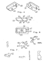
- the frame lock comprises a housing 16, made of a strong, bent plate material, roughly having a flat, elongated parallelepipedic shape, i.e. the house , which preferably consists of two symmetrical halves, has two wider main sides 17, which originate from a web 18, which extends roughly along half the length of the lock , within one of the narrow long sides 19, which has a hole 20 along its remaining portion.
- the other narrow long side 21 has a hole 22 opposite the web and is closed in the form of a bent web tongue 23 opposite hole 20.
- Gable side 24, adjacent web 18, is completely open, whereas gable side 25 roughly half of it is a hole 26, adjacent to said web tongues, and closed in the form of an end tongues 27, bent towards each other, originating from the main sides, as regards the other half of gable side 25, which preferably is transformed into said narrow long sides, designed as soft bends.
- Holes 20, 22 and 26 are limited by the attached bent portions 18, 23 and 27 by means of transverse notches 28, 29, 30, 31 and 32, which ensures, that the bendings will not affect the adjacent straight sections.
- Adjacent web 18 and hole 20 respectively the main sides are provided with crosswise through, preferably recessed bores 33 and 34 respectively, designed to receive screws or the like (not shown), anchored in the case.
- a crosswise through bearing bore 35 is made in the corner area between gable side 24 and web 18. These three bores are mirror-symmetrically located, allowing the frame lock to be mounted in said recess with either main side 17.
- the main sides of the frame lock are provided with notch embossings 36, which extend along the length of the greater part of the frame lock and are closed at their ends but are open against the interior of the house and originate from that side of hole 26, which is adjacent the end tongues. These notch embossings run parallel to the web tongues and are visible from outside in the form of bulgings .
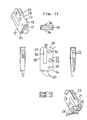
- the frame lock includes also a locking bar 42 as well as a connecting link 43.
- the locking bar is designed to be connected to locking house 16 via a revolving spindle 44 and shares with the link a first joint 45, whereas the link is designed to, with a second joint 46, mesh with coupling hole 37 in the corresponding locking rod end.
- revolving spindle 44 as well as joint 45 are located adjacent locking bar 42 in the form of one-sided spindle pins, which project in opposite directions and of which the one constituting revolving spindle 44 meshes with bearing bore 35, whereas said first joint 45 of link 43, mounted within the area of one end of the link, is designed as a bearing hole, running straight through and being designed to be pushed onto said second spindle pin 47 of the locking bar, which is a portion of said first joint.
- Said second joint 46 of the link, mounted at the second end of the link, is a hook, mounted transversely in relation to said bearing hole and which is designed to mesh with coupling hole 37 of the corresponding locking rod.
- the locking bar preferably has a mainly triangular shape with rounded triangle ends, one triangle end mainly concentrically surrounding said revolving spindle 44, whereas another triangle end mainly concentrically surrounds the other joint, e.g. the spindle pin mounted on the other main side.
- Side 65 which connects said two triangle ends to each other, is fairly straight
- the other triangle side 66 originating from revolving spindle 44, suitably is bent outwards.
- the third triangle side includes a preferably U-shaped hook 67, a claw 60 being formed as a triangle point and a concentric rounding of the locking bar, which extends around the greater portion of the revolving spindle, i.e. about 200°.
- Connecting link 43 can be half the thickness of the locking bar, since there is no risk, that e.g. during a burglary it is subjected to the same large stresses as the locking bar.
- the basic shape preferably is plate-like and between the two joints the link preferably is goose-necked to form two parts mutually displaced in parallel, joint 46 ending up in the centre plane of the locking bar.
- the portion with the last-mentioned joint has a hammer-like narrow shape, whereas the other link portion, starting from the other joint, will be continuously wider to optimize the guidance in house 3, a cavity 68 on the other side of the first joint allowing a pivoting of the link around the outer edge of web 18.
- An arbitrary locking plate 49 can be used for the locking itself in a frame recess 48. It will be fastened, with screws (not shown), in the frame wood or the like. However, it is particularly advantageous to use a special locking plate according to the invention, which is shown in Figs. 4 and 5 .
- This locking plate has an enlongated parallelepipedic shape and is made of a strong bent plate.
- One of gable sides 51 is bevel-shaped jointly with side surfaces 50 and bottom side 69 and holds a hole 53, suitably recessed from the interior in order to easily insert a screw (not shown), which is inserted through a first locking hole 55 in upper or covering side 52, which has a locking flange 54, turned in the direction from the gable side 51 in connection with locking hole 55, for said locking bar 42.
- Upper side 52 has, towards the other gable side 58, a second locking hole 57, which ends immediately in front of gable side 58 to form a locking flange 59, designed to hook up the locking bar with its claw 60 in an alternative locking position.
- These two locking positions may be called a closing position and a ventilation position.
- Hole 57 is made by punching out material from the upper side and bending it to obtain an oblique fastening tongue 61, which is mainly parallel with the gable side and is provided with a suitably bevelled screw hole 62.
- the tongue is connected to the upper side on the side, which faces away from locking flange 59.
- a screw not shown, is inserted into hole 57 and through screw hole 62 as well as through an e.g. oval hole 64 in the bottom side. In this way the locking plate will be fastened in the frame in a reliable way, entirely without visible screws and without screws accessible in a lateral direction.
- the upper side suitably will project laterally above the side surfaces and gable side 58 with a cover flange 56, in which holes, if necessary, for additional fastening screws can be made.
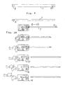
- Fig. 10 On each side of the adjusting mechanism four parts are to be assembled as a unit, i.e. a locking rod, a frame locking house, a locking bar and a link.
- the locking bar and the link are initially joined to each other, according to Fig. 10b .
- the locking bar is then inserted into the house, the width of which is larger than the transverse extension of the locking bar and the lip of the revolving spindle but is smaller than the total transverse extension of the locking bar and the two spindle pins, which constitute the revolving spindle and the first joint for the link.
- the link is then swung into the house completely, until its second joint is fastened in the hole of the guide hole.
- the locking rod is removed from the house again, according to Fig. 10f , the locking bar and the link following the locking rod and finally being completely withdrawn into the house.
- a joining obtained in this way, can be secured by fastening a friction lock, e.g. designed as a simple U-shaped clip 63, to the locking rod adjacent the house, in order to prevent the locking rod from being pushed inwards again.
- a friction lock e.g. designed as a simple U-shaped clip 63
- the locking bar during the entire assembling process is in an end position, where the locking bar has been swung out of the house beyond the locking position, referred to, in relation to the locking plate. It is solely in this end position possible to let the link swing into and out of the house, due to the length and the position of the link in relation to the web tongues, In case the locking bar and then also the link is swung just slightly into the house, then the second end of the link ends up below the web tongues and is secured in this way against a swinging out-movement.
- the locking bar and the link are secured in the house, because the inner width of the house is smaller than the total thickness of the locking bar and the two spindle pins, which project in different directions.
- the fastening screws for the house in the frame have to be removed first and then an excessive turning can be done and the link and then the locking bar and the locking rods can be removed.
- the insertion end of the locking rods in the adjusting mechanism suitably is finished by the manufacturer
- their frame locking ends suitably can be cut by a user, e.g. a window factory, to a suitable length and be provided with link holes.
- a user e.g. a window factory
- the house 16 and the other parts can of course be made according to other techniques and/or with other materials, e.g. plastic materials.
- the locking rods can, where appropriate, be combined with locking means, known per se, mounted along the length of the locking rods and implementing them in a lateral direction between two cases respectively.
- the locking bar and the link can be united, e.g. by riveting, before the mounting in the house.
- the locking bar can also, instead of its own stationary spindle, be provided with a straight through bore, into which a pin or the like is inserted straight through the house, to be used as a revolving spindle.
Landscapes
- Engineering & Computer Science (AREA)
- Mechanical Engineering (AREA)
- Hinges (AREA)
- Joining Of Building Structures In Genera (AREA)
- Connection Of Plates (AREA)
- Lock And Its Accessories (AREA)
- Clamps And Clips (AREA)
- Closing And Opening Devices For Wings, And Checks For Wings (AREA)
- Door And Window Frames Mounted To Openings (AREA)
- Input Circuits Of Receivers And Coupling Of Receivers And Audio Equipment (AREA)
- Auxiliary Devices For And Details Of Packaging Control (AREA)
Claims (10)
- Verriegelungsvorrichtung für einen in einer Tür- oder einem Fensterflügel (39) verankerten Espagnolette-Mechanismus (1), der einen zentral Nachstellmechanismus (2) enthält, von welchem Schlosstangen (7) die in untereinander entgegengesetzter Richtung ausgehen, deren freie Enden in Vertiefungen (41) in einem Rahmen (40) verankert sind, wobei ein Schlossriegel (42), der mittels der Schlosstangen am Rahmen um eine stationäre Drehachse (44) schwenkbar ist, welcher Schlossriegel (42) durch ein Verbindungsglied (43) mit Gelenkpunkten (45, 46) an seinen Enden in einem Schlosskasten (16) an der zugehörigen Schlosstange(7) befestigt ist, dadurch gekennzeichnet, dass der Schlossriegel (42) mittels besagter Drehachse (44) in einem Schlosskasten (16) verankert ist, und dass zuerst der Schlossriegel (42) und das Verbindungsglied (43) durch ein ersten Gelenkpunkt (45) in einer extremen Schwenkposition aneinander befestigt werden, und so angeordnet, um zusammen mit dem Verbindungsglied (43) in den Schlosskasten geschwenkt zu werden, der einen zweiten Gelenkpunkt (46) zur Verbindung mit dem Ende der entsprechenden Schlosstange im Schlosskasten aufweist, wobei die Drehachse (44) in eine Bohrung (35) im Schlosskasten des Rahmens für das Verbindungsglied (43) greift, und in der Schlosstange (42) ist ein Loch (37) vorgesehen für den anderen Gelenkpunkt (46), um ein Zurückschwenken des Schlossriegel (42) in Extremposition zu verhindern und um die Einheitlichkeit der Kopplung zu sichern.
- Verriegelungsvorrichtung nach Anspruch1, dadurch gekennzeichnet, dass die äußeren Enden der Schlosstangen (7) in ihre jeweiliges Rahmenschloss (15) greifen, das in einer nahe an dem Rahmen liegender Vertiefung (41) in besagtem Flügel (39) befestigt ist, deren Seiten dem Rahmen (40) zugewandte sind, und die besagten Kasten (16) enthalten, der vorzugsweise besteht aus einem starken, gebogenen Blech, ungefähr in Form einer flachen länglichen Parallelellipse besteht, wobei besagter Kasten, wenigstens zwei hauptsächlich symmetrische Hälften enthält, und der zwei breitere Hauptseiten (17) aufweiset, die von einem Steg (18) ausgehen, der sich ungefähr entlang der Hälfte des Rahmenschlosses (18) in einer der schmalen Längsseiten (19) erstreckt, die ein Loch (20) entlang des verbleibenden Teiles haben, und dass die andere schmale Längsseite (21) ein Loch ( 22) gegenüber besagten Steges aufweist und mit Hilfe der gebogenen Stegzunge (23) gegenüber dem zuerst genannten Loch (20) geschlossen ist, und dass die Giebelseite (24) am besagten Steg (18) anliegend, völlig geöffnet ist, während ungefähr die Hälfte der anderen Giebelseite (25) ein Loch (26) umfasst, das an besagter Stegzunge anliegt, und mittels des Zungenendes (27) geschlossen ist, gegen einander gebogenen Endzungen und von den die Hauptseiten ausgehen, betreffend die andere Hälfte der Giebelseite (25), welche vorzugsweisein in Form von weichen Rundungen in besagte schmale Längsseiten übergehen.
- Verriegelungsvorrichtung nach Anspruch 2, dadurch gekennzeichnet, dass besagte Löcher (20,22 und 26) gegen die angrenzenden gebogenen Teile (18, 23, und 27) mittels Querkerben (28, 29, 30, 31 und 32) abgegrenzt sind, um sicherzustellen, dass die Beugung nicht anliegende gerade Sektionen beeinträchtigt, und dass dicht am Steg (18) und am Loch (19), mit einer Verbindung auf gleicher Höhe zum Steg (18), deren Hauptseiten mit gerade durchgebohrten, teilweise versenkten Löcher m(33 bzw.34), ausgestattet sind, die dazu da sind die Schrauben oder dergleichen zum Verankern im Rahmen aufzunehmen, und dass sich im Eckenbereich zwischen der völlig geöffneten Giebelseite (24) und dem Steg (18) ein gerade durchgehendes Lagerloch (35) befindet, welche drei Löcher vorzugsweise spiegelsymmetrisch angeordnet sind, damit das Rahmenschloss in besagte Vertiefung geschoben werden kann mit entweder der einen oder der anderen Hauptseite (17).
- Verriegelungsvorrichtung nach Anspruch3, dadurch gekennzeichnet, dass die Hauptseite (17) und das Rahmenschloss (15) mit Kerbenprägungen ( 36) versehen sind, offen zum inneren des Gehäuses hin, endend in einem geschlossenen Zustand, ausgebreitet über den größten Teil der Länge des Rahmenschloss und ausgehend von der Seite des Loches (26), das an die Endzungen angrenzt, und dass besagte Kerbenprägungen parallel zu den Stegzungen laufen und von außen in Form von Ausbuchtungen sichtbar sind, und wobei sie so konstruiert sind, dass sie in einem die Einführung begrenzenden Weges die äußeren Enden der Schlossstangen (7) aufnehmen, die mit ihrer schmalen Seite in die Kerbenprägungen geführt werden und an ihren Enden, die dazu konstruiert sind, in das Rahmenschloss geführt zu werden, und die mit einem Kupplungsloch (37) versehen sind, das sich gerade durch die breite Seite erstreckt und das in das runde Loch passt.
- Verriegelungsvorrichtung nach Ansprüchen 1-4, dadurch gekennzeichnet, dass die Drehachse (44) als auch der Gelenkpunkt (45) am Schlossriegel (42) in Form von einseitigen Achszapfen angeordnet sind, welche in untereinander entgegengesetzten Richtungen hervorstehen, von denen der erste, der Zapfen, der die Drehachse ausmacht, in das Lagerloch (35) des Rahmenschlosskastens (16) greift, wobei besagter erster Gelenkpunkt (45) des Gliedes (43), angeordnet im Bereich von einem Gliedende, als ein gerade durchgehendes Lagerloch konstruiert ist, konstruiert um auf den zweiten Achselzapfen (47) montiert zu werden, welcher einen Teil besagten ersten Gelenkpunktes ausmacht, und in dem der zweite Gelenkpunkt (46) des Gliedes, angeordnet am anderen Ende des Gliedes, die Form eines Hakens hat, angeordnet gerade durch besagtes Lagerloch, dazu konstruiert ist in das Kopplungsloch (37) in der entsprechenden Schlossstange (7) zu greifen.
- Verriegelungsvorrichtung nach Ansprüchen 1-5, dadurch gekennzeichnet, dass die Schlossstange (42) ungefähr eine dreieckige Form mit runden Dreiecksenden hat, eines der Dreiecksenden ungefähr konzentrisch besagte Drehachse(44) umgebend, während die übrigen Dreiecksenden ungefähr konzentrisch die anderen Gelenkpunkte umgeben, z.B. den an der anderen Hauptseite angeordneten Achselzapfen, und dass die Seite (65), die besagte Dreiecksenden verbindet, zweckmäßigerweise gerade ist, während die zweite Dreiecksseite (66), die von der Drehachse (44) ausgeht, zweckmäßigerweise nach außen gebogen ist, und dass die dritte Dreiecksseite einen vorzugsweise U-geformten Haken (67) einschließt unter Bildung eines Klaue (60) als eine Dreieckspitze und eine konzentrische Rundung des Schlossriegels, der sich fast um die gesamte Drehachse streckt, d.h. etwa 200°.
- Verriegelungsvorrichtung nach Ansprüchen 1-6, dadurch gekennzeichnet, dass das Verbindungsglied (43) vorzugsweise nur halb so dick ist wie der Schlossriegel (42), und dass seine Grundform tellergleich und zwischen den beiden Gelenkpunkten gekröpft ist, um zwei untereinander versetzte Teile parallel zu einander zu erhalten, wobei der zweite Gelenkpunkt (46) in der zentralen Ebene des Schlossriegel endet, dessen Gelenkpunkt eine hammerförmige schmale Form aufweist, während das Gliedteil, das mit dem Schlossriegel verbunden ist, von dem obengenannten kontinuierlich breiter werdenden Gliedteil ausgeht, um die Führung in der Kasten (3) optimieren zu können, wobei eine Höhlung (68) an der anderen Seite des ersten Gelenkpunktes des Gliedes erlaubt ist, um um die äußere Ecke des Steges (18) geschwenkt zu werden.
- Verriegelungsvorrichtung nach Anspruch 1, dadurch gekennzeichnet, dass das Verriegelungsblech (49) die Form einer länglichen Parallelellipse hat und vorzugsweise aus einem starken gebogenen Blech hergestellt ist, dass eine der Giebelseiten (51) als Schräge zusammen mit seitlichen Oberflächen (50) und einer Unterseite (69) konstruiert ist und ein Loch enthält (53), zweckmäßigerweise vertieft von innen, um von innen eine Schraube einzuführen, die dafür vorgesehen ist, leicht durch eine erste Schlossöffnung (55) an der oberen oder Deckseite (52) eingeführt zu werden, welche in Richtung besagter Giebelseite, in Verbindung zur Schlossöffnung (55), einen ersten Verriegelungsflansch (54) für besagten Schlossriegel (42) aufweist, und welcher vorzugsweise, in Richtung auf die andere Giebelseite (58), eine zweite Verriegelungsöffnung (57) hat, welche direkt vor der zuletzt genannten Giebelseite (58) endet, um einen zweiten Verriegelungsflansch zu formen, konstruiert um den Schlossriegel mittels Klaue (60) in einer alternativen Verriegelungsposition zu befestigen.
- Verriegelungsvorrichtung nach Anspruch 8, dadurch gekennzeichnet, dass die zweite Schlossöffnung (57) aus ausgestanztem Material von der Deckseite gebildet und zu einer schrägen Befestigungszunge (61) gebogen wird, ungefähr parallel zur schrägen Giebelseite, die verbunden ist mit der Deckseite an der Seite, welche dem zweiten Verriegelungsflansch (59) abwendet ist, dass eine Befestigungsschraube vorgesehen ist, die durch besagte zweite Schlossöffnung (57) und durch das Schraubenloch (62) als auch durch ein z.B. ovalen Loch (64) an der Unterseite befestigt wird, um die Schlossriegel im Rahmen ohne sichtbare oder von der Seite erreichbare Schrauben zu verankern, und dass die obere Seite zweckmäßigerweise in seitlicher Richtung längs der seitlichen Oberfläche und der zweiten Giebelseite (58) mit einem Deckflansch (56) hervorsteht um die Montage zusätzlicher Befestigungsmittel zu ermöglichen.
- Verfahren zur Montage einer Verriegelungsvorrichtung an einem Espagnolette-Mechanismus (1), der zur Verankerung in einer Tür oder in einem Fensterflügel (39) vorgesehen ist gemäß einem der Ansprüchen 1-9, unter Benutzung eines zentralen Nachstellmechanismus (2) und Schlosstangen (7), die in untereinander entgegengesetzter Richtung gehen, deren freie Enden in Vertiefungen (41) in einem Rahmen (40) verankert sind, ein Schlossriegel (42), der mittels Schlosstangen um eine stationäre Drehachse (44) schwenkbar ist, für die Verriegelung gebraucht wird, dessen Schlossriegel durch ein Verbindungsglied (43) mit Gelenkpunkten (45, 46) an seinen Enden in einem Schlosskasten (16) an der dazugehörigen Schlosstange befestigt wird, dadurch gekennzeichnet, dass an jeder Seite des Nachstellmechanismus (2) vier Teile zu einer Einheit montiert sind, d.h. eine Schlosstange (7), ein Rahmenschlosskasten (16), ein Schlossriege (42) und ein Verbindungsglied (43), in dem zuerst der Schlossriegel und das Glied aneinander befestigt werden durch einen ersten Gelenkpunkt (45), dann der Schlossriegel in den Schlosskasten eingeführt wird, mit einer Breite größer als die Querbreite des Schlossriegels und der Länge der Drehachse, die aus ihm hervorsteht, aber schmaler als die totale Querbreite des Schlossriegel, des Verbindungsglied und der Länge besagter Achse, um die Einheit des Schlossriegels und des Gelenkpunktes zur Einführung ins Gehäuse zuzugestehen, nur wenn der Gelenkpunkt in seiner Gesamtheit außerhalb seines Schlossriegels gehalten wird, in den Rahmenschlosskasten eingeführt, dann versetzt in Querrichtung, wobei die Drehachse in eine Bohrung (35), die für diesen Zweck vorgesehen ist, im Schlosskasten des Rahmen greift, wobei besagter Schlosstange, die dann mit ihrem Kopplungsende bis zum Anschlag an die innere Kerbenprägungen (36) gedrückt wird, dann ist das Verbindungsglied (43) in den Kasten geschwenkt, wenn besagte seitliche Anordnung Platz gemacht hat für den Schlossriegel einschließlich des ersten Gelenkpunktes (45) des Gliedes, das Glied wird dann insgesamt in den Kasten geschwenkt, bis sein anderer Gelenkpunkt (46) in die Öffnung (37) im Stab hakt, der Verrieglungsstab wird dann aus dem Kasten gezogen, der Schlossriegel und das Glied folgen der Schlosstange und werden in den Kasten und der so erhaltenen Verbindung gezogen, vorzugsweise sichergestellt mittels eines Friktionsverschlusses (63) bis zur Montage in besagtem Fenster oder Türflügel (39).
Applications Claiming Priority (2)
| Application Number | Priority Date | Filing Date | Title |
|---|---|---|---|
| SE0302392A SE0302392L (sv) | 2003-09-05 | 2003-09-05 | Låsanordning samt sätt att montera en sådan |
| PCT/SE2004/000982 WO2005024163A1 (en) | 2003-09-05 | 2004-06-18 | A locking device and a method of assembling same |
Publications (2)
| Publication Number | Publication Date |
|---|---|
| EP1664467A1 EP1664467A1 (de) | 2006-06-07 |
| EP1664467B1 true EP1664467B1 (de) | 2010-06-30 |
Family
ID=28787280
Family Applications (1)
| Application Number | Title | Priority Date | Filing Date |
|---|---|---|---|
| EP20040749021 Expired - Lifetime EP1664467B1 (de) | 2003-09-05 | 2004-06-18 | Verriegelungsvorrichtung und montageverfahren dafür |
Country Status (8)
| Country | Link |
|---|---|
| US (1) | US7963573B2 (de) |
| EP (1) | EP1664467B1 (de) |
| AT (1) | ATE472654T1 (de) |
| DE (1) | DE602004027929D1 (de) |
| DK (1) | DK1664467T3 (de) |
| NO (1) | NO336541B1 (de) |
| SE (1) | SE0302392L (de) |
| WO (1) | WO2005024163A1 (de) |
Families Citing this family (18)
| Publication number | Priority date | Publication date | Assignee | Title |
|---|---|---|---|---|
| FR2913245B1 (fr) * | 2007-03-02 | 2013-08-30 | Metalux | Mecanisme de serrure et ouvrant comportant un tel mecanisme. |
| GB0815023D0 (en) * | 2008-08-16 | 2008-09-24 | Trojan Hardware & Designs Ltd | Espagnolettes |
| JP5629131B2 (ja) * | 2010-06-09 | 2014-11-19 | 株式会社ニフコ | ロック装置 |
| US9797173B2 (en) * | 2013-04-26 | 2017-10-24 | Locklatch (Pty) Ltd | Stay for locking a door, window or flap in a partly open position |
| WO2015134319A1 (en) * | 2014-03-04 | 2015-09-11 | Amesbury Group, Inc. | Deadbolt-activated supplemental lock |
| US10968661B2 (en) | 2016-08-17 | 2021-04-06 | Amesbury Group, Inc. | Locking system having an electronic deadbolt |
| US10941594B2 (en) * | 2017-02-13 | 2021-03-09 | Ford Global Technologies, Llc | Latch mechanism for storage box |
| CN106869658B (zh) | 2017-03-07 | 2018-08-07 | 希美克(广州)实业有限公司 | 一种自动停闭门装置及门 |
| CN110546340A (zh) | 2017-04-18 | 2019-12-06 | 埃美斯博瑞集团有限公司 | 模块化电子锁闩系统 |
| US10808424B2 (en) | 2017-05-01 | 2020-10-20 | Amesbury Group, Inc. | Modular multi-point lock |
| CN109296258A (zh) | 2017-07-25 | 2019-02-01 | 埃美斯博瑞集团有限公司 | 用于滑动门的进入把手 |
| CA3036398A1 (en) | 2018-03-12 | 2019-09-12 | Amesbury Group, Inc. | Electronic deadbolt systems |
| US11834866B2 (en) | 2018-11-06 | 2023-12-05 | Amesbury Group, Inc. | Flexible coupling for electronic deadbolt systems |
| US11661771B2 (en) | 2018-11-13 | 2023-05-30 | Amesbury Group, Inc. | Electronic drive for door locks |
| CA3121593C (en) * | 2018-12-21 | 2023-08-01 | Sargent Manufacturing Company | Side latch exit device |
| US11261626B2 (en) * | 2019-03-08 | 2022-03-01 | Volvo Car Corporation | Latch assembly including latch module with retractable latch bolt for storage compartment in automotive vehicle |
| US12560006B2 (en) * | 2022-03-29 | 2026-02-24 | Michael Reilly Design, Llc | Low profile multi-point lock drive |
| NL2031773B1 (en) * | 2022-05-04 | 2023-11-14 | Fort Noxs B V | Latching mechanism for a movable panel |
Family Cites Families (13)
| Publication number | Priority date | Publication date | Assignee | Title |
|---|---|---|---|---|
| DE333932C (de) | 1917-05-10 | 1921-03-07 | Emil Selander | Verschluss fuer Fenster, Tueren usw |
| US6217087B1 (en) * | 1994-12-07 | 2001-04-17 | Mark Weston Fuller | Lock mechanism |
| US5722704A (en) * | 1996-04-23 | 1998-03-03 | Reflectolite Products, Inc. | Multi-point door lock |
| SE507528C2 (sv) | 1996-10-16 | 1998-06-15 | Teknoskand Invent Ab | Låsanordning |
| US5820170A (en) * | 1997-01-21 | 1998-10-13 | Sash Controls, Inc. | Multi-point sliding door latch |
| US5901989A (en) * | 1997-07-16 | 1999-05-11 | Reflectolite | Multi-point inactive door lock |
| US6327879B1 (en) * | 1997-09-11 | 2001-12-11 | Pella Corporation | Locking mechanism for sliding glass doors |
| GB0016854D0 (en) * | 2000-07-11 | 2000-08-30 | Apw Electronics Ltd | Door latching mechanism |
| DE20017799U1 (de) | 2000-10-18 | 2000-12-28 | Gretsch-Unitas GmbH Baubeschläge, 71254 Ditzingen | Treibstangenverschluss |
| TW501633U (en) * | 2001-12-21 | 2002-09-01 | Chuen-Yi Liu | Door lock with double locking hooks |
| CA2403070C (en) * | 2002-09-13 | 2009-06-16 | Vanguard Plastics Ltd. | Mortise lock |
| US7040671B2 (en) * | 2003-01-28 | 2006-05-09 | Jyh-Huey Su, legal representative | Lock assembly with two hook devices |
| US7178839B2 (en) * | 2003-06-09 | 2007-02-20 | Imperial Usa, Ltd. | Latch assembly for sliding doors |
-
2003
- 2003-09-05 SE SE0302392A patent/SE0302392L/xx not_active IP Right Cessation
-
2004
- 2004-06-18 EP EP20040749021 patent/EP1664467B1/de not_active Expired - Lifetime
- 2004-06-18 DE DE200460027929 patent/DE602004027929D1/de not_active Expired - Lifetime
- 2004-06-18 DK DK04749021T patent/DK1664467T3/da active
- 2004-06-18 WO PCT/SE2004/000982 patent/WO2005024163A1/en not_active Ceased
- 2004-06-18 US US10/570,086 patent/US7963573B2/en not_active Expired - Fee Related
- 2004-06-18 AT AT04749021T patent/ATE472654T1/de not_active IP Right Cessation
-
2006
- 2006-01-31 NO NO20060490A patent/NO336541B1/no not_active IP Right Cessation
Also Published As
| Publication number | Publication date |
|---|---|
| US7963573B2 (en) | 2011-06-21 |
| DK1664467T3 (da) | 2010-09-13 |
| EP1664467A1 (de) | 2006-06-07 |
| US20070052246A1 (en) | 2007-03-08 |
| DE602004027929D1 (de) | 2010-08-12 |
| ATE472654T1 (de) | 2010-07-15 |
| WO2005024163A1 (en) | 2005-03-17 |
| NO20060490L (no) | 2006-05-29 |
| NO336541B1 (no) | 2015-09-21 |
| SE524191C2 (sv) | 2004-07-06 |
| SE0302392L (sv) | 2004-07-06 |
| SE0302392D0 (sv) | 2003-09-05 |
Similar Documents
| Publication | Publication Date | Title |
|---|---|---|
| US20070052246A1 (en) | Locking device and a method of assembling same | |
| CA2341966C (en) | Universal lock handle assembly for casement windows | |
| US6317928B1 (en) | Lockable hinge device | |
| JPH0771161A (ja) | 連接棒駆動装置 | |
| US3910612A (en) | Multiple bolt and keeper lock | |
| IL162344A (en) | Transmission rod for accessories for windows and doors | |
| US5581942A (en) | Method for the installation of a sash in the frame of a roof window | |
| EP1227207A2 (de) | Fensterbeschlag und Teile eines solchen Beschlages | |
| US6050114A (en) | Latch assembly of padlock for sliding doors | |
| JPH0771162A (ja) | 連接棒駆動装置 | |
| CA1211912A (en) | Hinge | |
| EP2447452A1 (de) | Schließblech für ein Schloss, Anordnung aus Schließblech und Schloss und/oder eines Schließelements und Verfahren zum Schließen eines Schließelements | |
| DE19816365A1 (de) | Verschwindscharnier | |
| GB2134205A (en) | Improvements in joints for connecting together hollow frame members | |
| US2832154A (en) | Router door latch and strike plate templet set | |
| JP2943726B2 (ja) | 結合部材 | |
| US2664181A (en) | Hollow metal door construction | |
| KR101772896B1 (ko) | 중공문짝의 잠금쇠 조립구조 및 조립방법 | |
| CN102016212A (zh) | 用于窗、门或者类似物体的配件以及带有该配件的窗、门或者类似物体,以及用于闩上和摇动支承窗扇的窗扇角的方法 | |
| RU2324801C2 (ru) | Окно или дверь | |
| PL183884B1 (pl) | Zasuwnica | |
| EP0706019A2 (de) | Verkaufsmöbeltür | |
| EP1580376B1 (de) | Scharnier für Türe und Fenster aus Metallprofilen | |
| JP7404439B2 (ja) | 建具枠連結構造及び建具枠連結具並びに建具枠連結方法 | |
| DE4444920C2 (de) | Vorrichtung aus mindestens zwei aufeinander legbaren Teilen eines Fensterflügels, Fensterrahmens oder Türblatts |
Legal Events
| Date | Code | Title | Description |
|---|---|---|---|
| PUAI | Public reference made under article 153(3) epc to a published international application that has entered the european phase |
Free format text: ORIGINAL CODE: 0009012 |
|
| 17P | Request for examination filed |
Effective date: 20060404 |
|
| AK | Designated contracting states |
Kind code of ref document: A1 Designated state(s): AT BE BG CH CY CZ DE DK EE ES FI FR GB GR HU IE IT LI LU MC NL PL PT RO SE SI SK TR |
|
| AX | Request for extension of the european patent |
Extension state: LT LV |
|
| RAX | Requested extension states of the european patent have changed |
Extension state: LV Payment date: 20060404 Extension state: LT Payment date: 20060404 |
|
| RAP1 | Party data changed (applicant data changed or rights of an application transferred) |
Owner name: STEELFORM SCANDINAVIA AB |
|
| 17Q | First examination report despatched |
Effective date: 20081105 |
|
| GRAP | Despatch of communication of intention to grant a patent |
Free format text: ORIGINAL CODE: EPIDOSNIGR1 |
|
| GRAS | Grant fee paid |
Free format text: ORIGINAL CODE: EPIDOSNIGR3 |
|
| GRAA | (expected) grant |
Free format text: ORIGINAL CODE: 0009210 |
|
| AK | Designated contracting states |
Kind code of ref document: B1 Designated state(s): AT BE BG CH CY CZ DE DK EE ES FI FR GB GR HU IE IT LI LU MC NL PL PT RO SE SI SK TR |
|
| AX | Request for extension of the european patent |
Extension state: LT LV |
|
| REG | Reference to a national code |
Ref country code: CH Ref legal event code: EP Ref country code: GB Ref legal event code: FG4D |
|
| REG | Reference to a national code |
Ref country code: IE Ref legal event code: FG4D |
|
| REF | Corresponds to: |
Ref document number: 602004027929 Country of ref document: DE Date of ref document: 20100812 Kind code of ref document: P |
|
| REG | Reference to a national code |
Ref country code: SE Ref legal event code: TRGR |
|
| REG | Reference to a national code |
Ref country code: DK Ref legal event code: T3 |
|
| REG | Reference to a national code |
Ref country code: NL Ref legal event code: VDEP Effective date: 20100630 |
|
| LTIE | Lt: invalidation of european patent or patent extension |
Effective date: 20100630 |
|
| PG25 | Lapsed in a contracting state [announced via postgrant information from national office to epo] |
Ref country code: SI Free format text: LAPSE BECAUSE OF FAILURE TO SUBMIT A TRANSLATION OF THE DESCRIPTION OR TO PAY THE FEE WITHIN THE PRESCRIBED TIME-LIMIT Effective date: 20100630 Ref country code: AT Free format text: LAPSE BECAUSE OF FAILURE TO SUBMIT A TRANSLATION OF THE DESCRIPTION OR TO PAY THE FEE WITHIN THE PRESCRIBED TIME-LIMIT Effective date: 20100630 |
|
| PG25 | Lapsed in a contracting state [announced via postgrant information from national office to epo] |
Ref country code: GR Free format text: LAPSE BECAUSE OF FAILURE TO SUBMIT A TRANSLATION OF THE DESCRIPTION OR TO PAY THE FEE WITHIN THE PRESCRIBED TIME-LIMIT Effective date: 20101001 Ref country code: PL Free format text: LAPSE BECAUSE OF FAILURE TO SUBMIT A TRANSLATION OF THE DESCRIPTION OR TO PAY THE FEE WITHIN THE PRESCRIBED TIME-LIMIT Effective date: 20100630 |
|
| PG25 | Lapsed in a contracting state [announced via postgrant information from national office to epo] |
Ref country code: EE Free format text: LAPSE BECAUSE OF FAILURE TO SUBMIT A TRANSLATION OF THE DESCRIPTION OR TO PAY THE FEE WITHIN THE PRESCRIBED TIME-LIMIT Effective date: 20100630 Ref country code: NL Free format text: LAPSE BECAUSE OF FAILURE TO SUBMIT A TRANSLATION OF THE DESCRIPTION OR TO PAY THE FEE WITHIN THE PRESCRIBED TIME-LIMIT Effective date: 20100630 |
|
| PG25 | Lapsed in a contracting state [announced via postgrant information from national office to epo] |
Ref country code: SK Free format text: LAPSE BECAUSE OF FAILURE TO SUBMIT A TRANSLATION OF THE DESCRIPTION OR TO PAY THE FEE WITHIN THE PRESCRIBED TIME-LIMIT Effective date: 20100630 Ref country code: CY Free format text: LAPSE BECAUSE OF FAILURE TO SUBMIT A TRANSLATION OF THE DESCRIPTION OR TO PAY THE FEE WITHIN THE PRESCRIBED TIME-LIMIT Effective date: 20100630 Ref country code: BE Free format text: LAPSE BECAUSE OF FAILURE TO SUBMIT A TRANSLATION OF THE DESCRIPTION OR TO PAY THE FEE WITHIN THE PRESCRIBED TIME-LIMIT Effective date: 20100630 Ref country code: CZ Free format text: LAPSE BECAUSE OF FAILURE TO SUBMIT A TRANSLATION OF THE DESCRIPTION OR TO PAY THE FEE WITHIN THE PRESCRIBED TIME-LIMIT Effective date: 20100630 Ref country code: PT Free format text: LAPSE BECAUSE OF FAILURE TO SUBMIT A TRANSLATION OF THE DESCRIPTION OR TO PAY THE FEE WITHIN THE PRESCRIBED TIME-LIMIT Effective date: 20101102 Ref country code: RO Free format text: LAPSE BECAUSE OF FAILURE TO SUBMIT A TRANSLATION OF THE DESCRIPTION OR TO PAY THE FEE WITHIN THE PRESCRIBED TIME-LIMIT Effective date: 20100630 |
|
| PG25 | Lapsed in a contracting state [announced via postgrant information from national office to epo] |
Ref country code: IT Free format text: LAPSE BECAUSE OF FAILURE TO SUBMIT A TRANSLATION OF THE DESCRIPTION OR TO PAY THE FEE WITHIN THE PRESCRIBED TIME-LIMIT Effective date: 20100630 |
|
| PLBE | No opposition filed within time limit |
Free format text: ORIGINAL CODE: 0009261 |
|
| STAA | Information on the status of an ep patent application or granted ep patent |
Free format text: STATUS: NO OPPOSITION FILED WITHIN TIME LIMIT |
|
| 26N | No opposition filed |
Effective date: 20110331 |
|
| PG25 | Lapsed in a contracting state [announced via postgrant information from national office to epo] |
Ref country code: ES Free format text: LAPSE BECAUSE OF FAILURE TO SUBMIT A TRANSLATION OF THE DESCRIPTION OR TO PAY THE FEE WITHIN THE PRESCRIBED TIME-LIMIT Effective date: 20101011 |
|
| REG | Reference to a national code |
Ref country code: DE Ref legal event code: R097 Ref document number: 602004027929 Country of ref document: DE Effective date: 20110330 |
|
| REG | Reference to a national code |
Ref country code: CH Ref legal event code: PL |
|
| REG | Reference to a national code |
Ref country code: FR Ref legal event code: ST Effective date: 20120229 |
|
| REG | Reference to a national code |
Ref country code: IE Ref legal event code: MM4A |
|
| REG | Reference to a national code |
Ref country code: DE Ref legal event code: R119 Ref document number: 602004027929 Country of ref document: DE Effective date: 20120103 |
|
| PG25 | Lapsed in a contracting state [announced via postgrant information from national office to epo] |
Ref country code: FR Free format text: LAPSE BECAUSE OF NON-PAYMENT OF DUE FEES Effective date: 20110630 Ref country code: IE Free format text: LAPSE BECAUSE OF NON-PAYMENT OF DUE FEES Effective date: 20110618 Ref country code: LI Free format text: LAPSE BECAUSE OF NON-PAYMENT OF DUE FEES Effective date: 20110630 Ref country code: CH Free format text: LAPSE BECAUSE OF NON-PAYMENT OF DUE FEES Effective date: 20110630 Ref country code: DE Free format text: LAPSE BECAUSE OF NON-PAYMENT OF DUE FEES Effective date: 20120103 |
|
| PG25 | Lapsed in a contracting state [announced via postgrant information from national office to epo] |
Ref country code: MC Free format text: LAPSE BECAUSE OF NON-PAYMENT OF DUE FEES Effective date: 20110630 |
|
| PG25 | Lapsed in a contracting state [announced via postgrant information from national office to epo] |
Ref country code: LU Free format text: LAPSE BECAUSE OF NON-PAYMENT OF DUE FEES Effective date: 20110618 |
|
| PG25 | Lapsed in a contracting state [announced via postgrant information from national office to epo] |
Ref country code: BG Free format text: LAPSE BECAUSE OF FAILURE TO SUBMIT A TRANSLATION OF THE DESCRIPTION OR TO PAY THE FEE WITHIN THE PRESCRIBED TIME-LIMIT Effective date: 20100930 Ref country code: TR Free format text: LAPSE BECAUSE OF FAILURE TO SUBMIT A TRANSLATION OF THE DESCRIPTION OR TO PAY THE FEE WITHIN THE PRESCRIBED TIME-LIMIT Effective date: 20100630 |
|
| PG25 | Lapsed in a contracting state [announced via postgrant information from national office to epo] |
Ref country code: HU Free format text: LAPSE BECAUSE OF FAILURE TO SUBMIT A TRANSLATION OF THE DESCRIPTION OR TO PAY THE FEE WITHIN THE PRESCRIBED TIME-LIMIT Effective date: 20100630 |
|
| PGFP | Annual fee paid to national office [announced via postgrant information from national office to epo] |
Ref country code: DK Payment date: 20180611 Year of fee payment: 15 Ref country code: FI Payment date: 20180614 Year of fee payment: 15 |
|
| PGFP | Annual fee paid to national office [announced via postgrant information from national office to epo] |
Ref country code: SE Payment date: 20180611 Year of fee payment: 15 |
|
| PGFP | Annual fee paid to national office [announced via postgrant information from national office to epo] |
Ref country code: GB Payment date: 20180608 Year of fee payment: 15 |
|
| REG | Reference to a national code |
Ref country code: FI Ref legal event code: MAE |
|
| REG | Reference to a national code |
Ref country code: DK Ref legal event code: EBP Effective date: 20190630 |
|
| REG | Reference to a national code |
Ref country code: SE Ref legal event code: EUG |
|
| PG25 | Lapsed in a contracting state [announced via postgrant information from national office to epo] |
Ref country code: SE Free format text: LAPSE BECAUSE OF NON-PAYMENT OF DUE FEES Effective date: 20190619 Ref country code: FI Free format text: LAPSE BECAUSE OF NON-PAYMENT OF DUE FEES Effective date: 20190618 |
|
| GBPC | Gb: european patent ceased through non-payment of renewal fee |
Effective date: 20190618 |
|
| PG25 | Lapsed in a contracting state [announced via postgrant information from national office to epo] |
Ref country code: GB Free format text: LAPSE BECAUSE OF NON-PAYMENT OF DUE FEES Effective date: 20190618 |
|
| PG25 | Lapsed in a contracting state [announced via postgrant information from national office to epo] |
Ref country code: DK Free format text: LAPSE BECAUSE OF NON-PAYMENT OF DUE FEES Effective date: 20190630 |