EP1580376B1 - Scharnier für Türe und Fenster aus Metallprofilen - Google Patents
Scharnier für Türe und Fenster aus Metallprofilen Download PDFInfo
- Publication number
- EP1580376B1 EP1580376B1 EP05102230A EP05102230A EP1580376B1 EP 1580376 B1 EP1580376 B1 EP 1580376B1 EP 05102230 A EP05102230 A EP 05102230A EP 05102230 A EP05102230 A EP 05102230A EP 1580376 B1 EP1580376 B1 EP 1580376B1
- Authority
- EP
- European Patent Office
- Prior art keywords
- arm
- hinge
- doors
- rib
- windows
- Prior art date
- Legal status (The legal status is an assumption and is not a legal conclusion. Google has not performed a legal analysis and makes no representation as to the accuracy of the status listed.)
- Expired - Lifetime
Links
- 229910052751 metal Inorganic materials 0.000 title claims abstract description 14
- 239000002184 metal Substances 0.000 title claims abstract description 14
- 230000008878 coupling Effects 0.000 claims abstract description 15
- 238000010168 coupling process Methods 0.000 claims abstract description 15
- 238000005859 coupling reaction Methods 0.000 claims abstract description 15
- 238000003780 insertion Methods 0.000 claims description 3
- 230000037431 insertion Effects 0.000 claims description 3
- 238000006073 displacement reaction Methods 0.000 claims description 2
- 238000000034 method Methods 0.000 description 5
- 239000004411 aluminium Substances 0.000 description 2
- 229910052782 aluminium Inorganic materials 0.000 description 2
- XAGFODPZIPBFFR-UHFFFAOYSA-N aluminium Chemical compound [Al] XAGFODPZIPBFFR-UHFFFAOYSA-N 0.000 description 2
- 244000182067 Fraxinus ornus Species 0.000 description 1
- 238000012986 modification Methods 0.000 description 1
- 230000004048 modification Effects 0.000 description 1
Images


Classifications
-
- E—FIXED CONSTRUCTIONS
- E05—LOCKS; KEYS; WINDOW OR DOOR FITTINGS; SAFES
- E05D—HINGES OR SUSPENSION DEVICES FOR DOORS, WINDOWS OR WINGS
- E05D5/00—Construction of single parts, e.g. the parts for attachment
- E05D5/02—Parts for attachment, e.g. flaps
- E05D5/0215—Parts for attachment, e.g. flaps for attachment to profile members or the like
- E05D5/0223—Parts for attachment, e.g. flaps for attachment to profile members or the like with parts, e.g. screws, extending through the profile wall or engaging profile grooves
- E05D5/0238—Parts for attachment, e.g. flaps for attachment to profile members or the like with parts, e.g. screws, extending through the profile wall or engaging profile grooves with parts engaging profile grooves
-
- E—FIXED CONSTRUCTIONS
- E05—LOCKS; KEYS; WINDOW OR DOOR FITTINGS; SAFES
- E05D—HINGES OR SUSPENSION DEVICES FOR DOORS, WINDOWS OR WINGS
- E05D15/00—Suspension arrangements for wings
- E05D15/48—Suspension arrangements for wings allowing alternative movements
- E05D15/52—Suspension arrangements for wings allowing alternative movements for opening about a vertical as well as a horizontal axis
- E05D15/5214—Corner supports
-
- E—FIXED CONSTRUCTIONS
- E05—LOCKS; KEYS; WINDOW OR DOOR FITTINGS; SAFES
- E05Y—INDEXING SCHEME ASSOCIATED WITH SUBCLASSES E05D AND E05F, RELATING TO CONSTRUCTION ELEMENTS, ELECTRIC CONTROL, POWER SUPPLY, POWER SIGNAL OR TRANSMISSION, USER INTERFACES, MOUNTING OR COUPLING, DETAILS, ACCESSORIES, AUXILIARY OPERATIONS NOT OTHERWISE PROVIDED FOR, APPLICATION THEREOF
- E05Y2900/00—Application of doors, windows, wings or fittings thereof
- E05Y2900/10—Application of doors, windows, wings or fittings thereof for buildings or parts thereof
- E05Y2900/13—Type of wing
- E05Y2900/132—Doors
-
- E—FIXED CONSTRUCTIONS
- E05—LOCKS; KEYS; WINDOW OR DOOR FITTINGS; SAFES
- E05Y—INDEXING SCHEME ASSOCIATED WITH SUBCLASSES E05D AND E05F, RELATING TO CONSTRUCTION ELEMENTS, ELECTRIC CONTROL, POWER SUPPLY, POWER SIGNAL OR TRANSMISSION, USER INTERFACES, MOUNTING OR COUPLING, DETAILS, ACCESSORIES, AUXILIARY OPERATIONS NOT OTHERWISE PROVIDED FOR, APPLICATION THEREOF
- E05Y2900/00—Application of doors, windows, wings or fittings thereof
- E05Y2900/10—Application of doors, windows, wings or fittings thereof for buildings or parts thereof
- E05Y2900/13—Type of wing
- E05Y2900/148—Windows
Definitions
- the present invention relates in general to the field of the accessories for doors and windows in metal section bars, in particular section bars in aluminium.
- the object of the present invention is a hinge which can be used in aluminium doors or windows of the wing type or tilt and turn type.
- the wings of doors and windows are connected to the respective frames by means of hinges formed by two reciprocal coupling elements consisting more particularly of a male element and a female element rotatingly engaged one in the other.
- Each element of rotating reciprocal coupling comprises a hinge pin or respectively a hinge housing for the engaging of said pin.
- the two elements can be connected to the frame or to the wing irrespectively; more frequently, in the case of doors or windows in metal section bar, the male element is connected to the wing, but in some cases, both the wing and the frame have female elements, which can be aligned at assembly and pivotally connected to each other by a free pin engaged in the female elements.
- each coupling element comprises its own attachment means so as to be fixed to the respective structure, frame or wing.
- the coupling elements are fixed by the attachment means to the contact walls between the wing and the frame, that is to say those not visible nor accessible when the doors or windows is closed.
- each coupling element comprises a generally square attachment plate, wherefrom the pin or relative housing extends, and a counterplate between which the section bar forming the frame or the wing is placed. Fastening between the plate and counterplate is carried out by means of screws.
- hinges for doors or windows in metal section bar involves the use of numerous separate components (square plate, counterplate and screws) and can therefore only be used in a manual process of assembly of the doors or windows.
- another type of hinge for doors or windows such that disclosed in EP 528213 , the male and female member of the hinge can be connected to the respective door or window frames by locking devices that force the attachment menas against them, but still a manual assembly process is required.
- Other prior art examples of this type are shown in FR 2436247 , EP 649815 and EP 1258584 .
- a structure of this kind cannot be used in that assembly of the various components cannot be automated, except with extremely complex and costly equipment.
- the object of the present invention is to provide a hinge for doors or windows in metal section bars which enables assembly of the same by means of automatic machinery.
- a particular object of the present invention is to provide a hinge of the type mentioned above wherein the respective coupling elements are designed for fixed connection on the relative section bar, in this way allowing automatic assembly.
- the hinge according to the present invention is of the type that comprises two mutually and pivotally coupling elements, each intended to be attached either to the frame or to the wing of a door or window.
- Each coupling element comprises attachment means suitable for being engaged in respective grooved housings of the frame or of the wing and locking means engaged in the same grooved housings and operable for forcing the attachment means within the grooved housing to prevent them from sliding along the housings.
- the coupling elements are each formed by a square plate comprising a first arm and a second arm perpendicular to each other and the attachment means comprise a first longitudinal toothed rib fit for hooking to the respective grooved housing, while the locking means comprise an additional rib, toothed on the opposite side in relation to the first rib, and can be forcibly operated by means of a wedge or peg member so as to prevent sliding of the first ribbing in the respective housing.
- each mutually and pivotally coupling element comprises a hinge pin or, respectively, a hinge housing for the engaging of the pin extending from a square plate holding the attachment means and the locking means.
- the square plate comprises a first arm and a second arm perpendicular one to the other and a third arm, extending from the opposite side to the first arm in relation to the second arm, holding the pin or the housing.
- the first and the second ribbings extend on the same side along the first and the second arms.
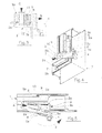
- a female element of the hinge according to the invention is made in a single shaped body wherefrom a housing 4 extends for the engaging of a pin, not shown.
- the female element 3 also comprises an attachment body 5, with a substantially square shape and comprising a first arm 5a and a second arm 5b, perpendicular one to the other, and a third arm 5c, extending from the opposite side to the arm 5b in relation to the arm 5a and holding the housing 4 at its free end.
- Respective longitudinal toothed ribs 6 and 7 are formed along the external faces of the two arms 5a and 5b.
- the first rib 6, which extends along the arm 5a of the anchorage body 5, has a bevelled edge 6a and, at the opposite side, a longitudinal tooth 6b.
- On the second arm 5b a substantially U-shaped through notch 8 is formed which defines on the same arm 5b a portion 9 with an elongated shape, referred to for the sake of simplicity as tongue, connected flexibly to the arm 5b via its root 9a.
- the main sides of the notch 8 extend longitudinally on the arm 5b, so that the tongue 9 extends from approximately the free end of the arm 5b towards the arm 5a.
- one of the branches of the notch 8, denoted by 8a has a widening 10 intended for the forced engaging of a wedge or peg body 11, shown in an exploded view in Figures 1 and 2 , whose function shall be described herein below.
- the rib 7 also with teeth and extending along the second arm 5b, has an enlarged edge 12, with a substantial tooth shape, at its portion coinciding with the notch 8 and along the other side 8b of the latter.
- assembly of the female element 3 on the frame 1 is performed as follows.
- the first arm 5a is first engaged in the grooved housing 2 of the frame 1. This is performed by moving the attachment body 5 closer in the entry direction indicated by the arrow A (in Figure 5 ), so as to hook the longitudinal tooth 6b under the relative fin 2a. With a rotary movement as indicated by the arrow B, the first rib 6 is inserted in the housing 2 thanks to the presence of the bevelled edge 6a. The first arm 5a is then made to slide along the portion of the groove 2 wherein the first rib 6 is engaged until the second longitudinal rib 7 is engaged in the respective portion of the groove 2. At this point the female element 3 is positioned in the corner of the frame, without however being attached there.
- the peg 11 In order to lock it in this position the peg 11 is engaged in the widening 10 (arrow C in Figure 3 ) and, being of a larger size than the widening 10, causes a displacement, in the direction of the arrow D ( Fig. 3 ), of the tongue 9 which bends correspondingly around its root 9a. More specifically, as can also be seen in Figure 3 , the peg 11 has a frusto-conical portion whose smallest diameter is smaller than that of the widening 10 and a stem of larger diameter. More particularly the difference between the values of the diameter of the stem of the peg 11 and of the diameter of the widening 10 gauges the extent of the movement of the edge 12 of the tongue 9.
- the enlarged edge 12 of the tongue 9 is forced against the fin 2b of the grooved housing 2, hooking it and generating a friction force which prevents the sliding of the first ribbing, and hence of the entire female element, in the groove 2.
- the presence of the longitudinal tooth 6b and of the enlarged edge 12 allows fixing of the attachment body 5 to the frame 1 without the use of screws.
- the sequence of insertion of the body 5 in the frame 1 in the directions indicated by arrows A, B, C, D also allows definition of a process of assembly of the individual elements of coupling of the hinge composed of simple linear movements which can be implemented by means of an automatic assembly machine.
- the hinge for doors or windows in metal section bar according to the invention therefore solves the problems of hinges according to the prior art in that, thanks to its shape, it can be fixedly connected to the wing or to the frame without the aid of screws and counterplates.
- the simplicity of the movements required for the connection makes it particularly suitable for use in a line for production of doors or windows by means of machines operating automatically.
- Figures 6 and 7 show a male element 23 of a hinge intended to be attached to the frame of the wing and then to the external edge thereof.
- the male element 23 is also made in a single shaped body wherefrom the hinge pin 24 extends for engaging in a hinge housing, such as the housing 4, of the female element 3.
- the male element 23 also comprises an attachment body 25 of a substantially square shape and composed of two perpendicular arms 25a, 25b and a third arm 25c, extending from the opposite side to the arm 25b in relation to the arm 25a and holding the housing 24 at its free end.
- the attachment and locking means are consequently provided on the internal faces of the body 25.
- the arm 25a has a rib 26 with two projections 26a extending symmetrically from opposite sides to its free end.
- the ribbing 26 has such a width as to engage in the grooved housing 2, while the two projections 26a abut from the inside on the two fins 2a, 2b once the rib 26 is engaged in the housing 2.
- the arm 25b has a rib 27 and a through notch 28 defining a portion 29 with elongated shape, referred to for the sake of simplicity as tongue, comprising at least one part of the rib 27 and connected flexibly to the arm 25b via its root 29a.
- the notch extends along the arm 25b in a substantially longitudinal direction and the root 29a is near the other arm 25a.
- the notch 28 has a widening 30 intended for forcedly engaging a peg 31 identical to the peg 11 described previously.
- the toothed ribbing 26 is first inserted slidingly from below in the grooved housing 2 until it engages the rib 27 in the corresponding grooved housing, making the arm 25b abut on the fins 2a, 2b.
- the peg 31 is forcedly inserted in the widening 30, this resulting in a forced abutment of the arm 25b against the fins 2a, 2b and the side walls of the grooved housing 2 and the locking of the male element 23 on the wing frame.
Landscapes
- Engineering & Computer Science (AREA)
- Mechanical Engineering (AREA)
- Hinges (AREA)
- Wing Frames And Configurations (AREA)
- Glass Compositions (AREA)
- Refrigerator Housings (AREA)
Claims (8)
- Scharnier für Türen oder Fenster aus Metallprofilstab, enthaltend zwei wechselseitig und drehbar koppelnde Elemente (3, 23), die an dem Rahmen und an dem Flügel der Türen oder Fenster befestigbar sind, wobei jedes der Kopplungselemente Befestigungseinrichtungen (6, 7, 26, 27), die geeignet sind, um in entsprechend genuteten Gehäusen (2), die in dem Rahmen bzw. dem Flügel ausgebildet sind, in Eingriff zu sein, und Verriegelungseinrichtungen (9, 11, 29, 31), hat, die betätigbar sind, um die Befestigungseinrichtungen in die genuteten Gehäuse zu drängen, um sie daran zu hindern, sich längs der Gehäuse (2) zu verschieben, dadurch gekennzeichnet, dass die Kopplungselemente (3, 23) jeweils durch eine eckige Platte (5, 25) gebildet sind, die einen ersten Arm (5a, 25a) und einen zweiten Arm (5b, 25b) senkrecht zueinander enthält, und die Befestigungseinrichtungen eine erste gezahnte Rippe (6, 26) enthalten, die sich von dem ersten Arm (5a, 25a) aus erstreckt, um innerhalb des genuteten Gehäuses (2) einzuhaken, welcher zweite Arm (5b, 25b) mit einer durchgehenden Ausnehmung (8, 28) ausgebildet ist, die einen einstellbaren Teil (9, 29) daran definiert, von welchem sich eine zweite Rippe (7, 27) erstreckt, welche Verriegelungseinrichtungen einen Keilkörper (11, 31) enthalten, der passend ist, um zwischen dem verstellbaren Teil (9, 29) und dem verbleibenden Teil des zweiten Arms (5b, 25b) angeordnet zu werden, wodurch die zweite Rippe (7, 27) gegen die genuteten Gehäuse gedrängt wird, um eine Reibkraft zu entwickeln, die geeignet ist, um die erste Rippe (6, 26) daran zu hindern, sich darin zu verschieben.
- Scharnier für Türen oder Fenster nach Anspruch 1, wobei die zweite Rippe (7) an der entgegengesetzten Seite in Bezug auf einen Zahn (6b) der ersten Rippe (6) einen vergrößerten Rand (12) hat, der geeignet ist, um als ein Ergebnis einer Verstellung des verstellbaren Teils (9) einzuhaken an dem und zu drücken gegen gegen das genutete Gehäuse (2) .
- Scharnier für Türen oder Fenster nach einem der vorhergehenden Ansprüche, wobei jedes wechselseitig und drehbar koppelnde Element einen Scharnierstift (24) oder entsprechend ein Scharniergehäuse (4) zum Eingriff mit dem Stift hat, der/das sich von der eckigen Platte (5, 25) aus erstreckt, die die Befestigungseinrichtungen (6, 7, 26, 27) und die Verriegelungseinrichtungen (9, 11, 29, 31) hält, welche eckige Platte einen dritten Arm (5c, 25c) enthält, der sich von der entgegengesetzten Seite zu dem ersten Arm in Relation zu dem zweiten Arm den Stift (24) oder das Gehäuse (4) haltend erstreckt, welche erste und zweite Rippe (6, 7, 26, 27) sich von derselben Seite längs des ersten und zweiten Arms (5a, 5b, 25a, 25b) erstrecken.
- Scharnier für Türen oder Fenster nach Anspruch 3, wobei an dem zweiten Arm (5b) eine im wesentlichen U-förmige durchgehende Ausnehmung (8) ausgebildet ist, die den verstellbaren Teil (9) des Arms definiert, wovon die zweite Rippe (7) ausgeht, wobei ein Sitz (10) längs der durchgehenden Ausnehmung (8) für die erzwungene Einsetzung des Keilkörpers (11) vorgesehen ist.
- Scharnier für Türen oder Fenster nach Anspruch 4, wobei der durch die im wesentlichen U-förmige durchgehende Ausnehmung (8) definierte verstellbare Teil (9) des zweiten Arms eine längliche Form hat, die von einem Ursprung (9a) des Anschlusses des Arms startet, welcher Sitz (10) für den Keilkörper (11) nahe dem freien Ende davon und an der entgegengesetzten Seite zu dem gezahnten Rand (12) der zweiten Rippe (7) vorgesehen ist.
- Scharnier für Türen oder Fenster nach einem der Ansprüche 1 bis 3, wobei an dem zweiten Arm (25b) eine im wesentlichen längliche durchgehende Ausnehmung (28) ausgebildet ist, die einen verstellbaren Teil (29) des Arms definiert, wovon sich wenigstens ein Teil der zweiten Rippe (27) erstreckt, wobei ein Sitz (30) längs der Ausnehmung zur erzwungenen Einsetzung des Keilkörpers (31) vorgesehen ist.
- Scharnier für Türen oder Fenster nach Anspruch 6, wobei sich die Ausnehmung (28) von dem ersten Arm (25a) ungefähr so weit wie ein Seitenrand des zweiten Arms (25b) erstreckt, was ein freies Ende des verstellbaren Teils (29) definiert, in dessen Nähe der Sitz (30) ausgebildet ist.
- Scharnier für Türen oder Fenster nach einem der vorhergehenden Ansprüche, wobei der Keilkörper (11, 31) ein Stift mit einem Schaft von größerem Durchmesser als der Durchmesser des Sitzes (10, 30) und einem frusto-konischen freien Ende mit einem kleineren minimalen Durchmesser als der Durchmesser des Sitzes ist.
Priority Applications (1)
| Application Number | Priority Date | Filing Date | Title |
|---|---|---|---|
| PL05102230T PL1580376T3 (pl) | 2004-03-24 | 2005-03-21 | Zawias do drzwi lub okien wykonanych z metalowych listew profilowanych |
Applications Claiming Priority (2)
| Application Number | Priority Date | Filing Date | Title |
|---|---|---|---|
| ITFI20040074 | 2004-03-24 | ||
| IT000074A ITFI20040074A1 (it) | 2004-03-24 | 2004-03-24 | Cerniera per serramenti in profilati metallici |
Publications (2)
| Publication Number | Publication Date |
|---|---|
| EP1580376A1 EP1580376A1 (de) | 2005-09-28 |
| EP1580376B1 true EP1580376B1 (de) | 2008-11-19 |
Family
ID=34856898
Family Applications (1)
| Application Number | Title | Priority Date | Filing Date |
|---|---|---|---|
| EP05102230A Expired - Lifetime EP1580376B1 (de) | 2004-03-24 | 2005-03-21 | Scharnier für Türe und Fenster aus Metallprofilen |
Country Status (7)
| Country | Link |
|---|---|
| EP (1) | EP1580376B1 (de) |
| AT (1) | ATE414835T1 (de) |
| DE (1) | DE602005011065D1 (de) |
| ES (1) | ES2314562T3 (de) |
| IT (1) | ITFI20040074A1 (de) |
| PL (1) | PL1580376T3 (de) |
| PT (1) | PT1580376E (de) |
Families Citing this family (2)
| Publication number | Priority date | Publication date | Assignee | Title |
|---|---|---|---|---|
| DE102008010906A1 (de) * | 2008-02-23 | 2009-09-17 | Roto Frank Ag | Beschlagteilanordnung |
| DE102010028602A1 (de) * | 2010-05-05 | 2011-11-10 | Roto Frank Ag | Verdeckt liegender Ecklagerbeschlag mit einem Niederhalter |
Family Cites Families (4)
| Publication number | Priority date | Publication date | Assignee | Title |
|---|---|---|---|---|
| DE7827333U1 (de) | 1978-09-14 | 1979-01-04 | Schueco Heinz Schuermann Gmbh & Co, 4800 Bielefeld | Drehkippfenster |
| DE9110175U1 (de) | 1991-08-16 | 1991-10-02 | Ferco International, Sarrebourg | Beschlagteil zur Klemmbefestigung in einer mindestens einseitig hinterschnittenen Profilnut |
| DE59502474D1 (de) | 1994-09-02 | 1998-07-16 | Roto Frank Ag | Klemmvorrichtung zum Befestigen eines Beschlagteils und Verfahren zur Herstellung einer derartigen Klemmvorrichtung |
| FR2824864B1 (fr) | 2001-05-18 | 2004-06-04 | Bezault Sa | Paumelle et son procede de montage |
-
2004
- 2004-03-24 IT IT000074A patent/ITFI20040074A1/it unknown
-
2005
- 2005-03-21 ES ES05102230T patent/ES2314562T3/es not_active Expired - Lifetime
- 2005-03-21 AT AT05102230T patent/ATE414835T1/de not_active IP Right Cessation
- 2005-03-21 EP EP05102230A patent/EP1580376B1/de not_active Expired - Lifetime
- 2005-03-21 PT PT05102230T patent/PT1580376E/pt unknown
- 2005-03-21 PL PL05102230T patent/PL1580376T3/pl unknown
- 2005-03-21 DE DE602005011065T patent/DE602005011065D1/de not_active Expired - Lifetime
Also Published As
| Publication number | Publication date |
|---|---|
| DE602005011065D1 (de) | 2009-01-02 |
| EP1580376A1 (de) | 2005-09-28 |
| ATE414835T1 (de) | 2008-12-15 |
| ITFI20040074A1 (it) | 2004-06-24 |
| PT1580376E (pt) | 2009-01-27 |
| ES2314562T3 (es) | 2009-03-16 |
| PL1580376T3 (pl) | 2009-04-30 |
Similar Documents
| Publication | Publication Date | Title |
|---|---|---|
| US6772480B2 (en) | Fitting having support arm or swing arm for supporting a turning sash or a turning-tilting sash | |
| DE102007023019B4 (de) | Verriegelungsbügel für Steckverbindergehäuse | |
| EP1664467B1 (de) | Verriegelungsvorrichtung und montageverfahren dafür | |
| US3543545A (en) | Combination lock | |
| EP3472414B1 (de) | Kraftfahrzeug-griffanordnung | |
| EP1580376B1 (de) | Scharnier für Türe und Fenster aus Metallprofilen | |
| US6050114A (en) | Latch assembly of padlock for sliding doors | |
| JPH0771162A (ja) | 連接棒駆動装置 | |
| EP0916793A1 (de) | Ein Sicherheit Scharnier | |
| EP1219768B1 (de) | Mechanische Verbindungsanordnung für Umfangsverriegelungsvorrichtung von einbruchsicheren aus Metallprofilen bestehenden Tür- und Fensterflügeln | |
| EP0844709A2 (de) | Gehäuse für elektrisches Gerät | |
| EP1297233B1 (de) | Schliessystem für fenster, türen und dergleichen | |
| US6068304A (en) | Espagnolette edge bar assembly | |
| EP2826934A2 (de) | Verriegelungstaschen-Baugruppe im Blendrahmen mit erhöhtem Einbruchschutz | |
| ITUB20154888A1 (it) | Soluzione per il fissaggio reciproco di parti componenti di un sistema di chiusura, in particolare per infissi | |
| EP1718829B1 (de) | Vorrichtung an einem abdeckelement | |
| EP2924208B1 (de) | Gegen gewaltsames eindringen beständiges schloss | |
| EP4206426B1 (de) | Eckumlenkung für fensterbeschläge | |
| EP1479862A2 (de) | Betätigungsvorrichtung für Türen und Fenster | |
| DE102008058291B4 (de) | Gehäuse für ein elektronisches Gerät | |
| EP1700984A2 (de) | Anstossplatte für eine Schliesseinrichtung eines Fensterflügels | |
| AU2004201359B2 (en) | A Security Bolt | |
| EP0727552A2 (de) | Doppelbartschloss | |
| HU223255B1 (hu) | Rúdzárház | |
| US4699413A (en) | Auxiliary door latch |
Legal Events
| Date | Code | Title | Description |
|---|---|---|---|
| PUAI | Public reference made under article 153(3) epc to a published international application that has entered the european phase |
Free format text: ORIGINAL CODE: 0009012 |
|
| AK | Designated contracting states |
Kind code of ref document: A1 Designated state(s): AT BE BG CH CY CZ DE DK EE ES FI FR GB GR HU IE IS IT LI LT LU MC NL PL PT RO SE SI SK TR |
|
| AX | Request for extension of the european patent |
Extension state: AL BA HR LV MK YU |
|
| 17P | Request for examination filed |
Effective date: 20051130 |
|
| AKX | Designation fees paid |
Designated state(s): AT BE BG CH CY CZ DE DK EE ES FI FR GB GR HU IE IS IT LI LT LU MC NL PL PT RO SE SI SK TR |
|
| RAP1 | Party data changed (applicant data changed or rights of an application transferred) |
Owner name: EUROINVEST S.P.A. |
|
| GRAP | Despatch of communication of intention to grant a patent |
Free format text: ORIGINAL CODE: EPIDOSNIGR1 |
|
| GRAS | Grant fee paid |
Free format text: ORIGINAL CODE: EPIDOSNIGR3 |
|
| GRAA | (expected) grant |
Free format text: ORIGINAL CODE: 0009210 |
|
| AK | Designated contracting states |
Kind code of ref document: B1 Designated state(s): AT BE BG CH CY CZ DE DK EE ES FI FR GB GR HU IE IS IT LI LT LU MC NL PL PT RO SE SI SK TR |
|
| REG | Reference to a national code |
Ref country code: GB Ref legal event code: FG4D |
|
| REG | Reference to a national code |
Ref country code: CH Ref legal event code: EP |
|
| REG | Reference to a national code |
Ref country code: IE Ref legal event code: FG4D |
|
| REF | Corresponds to: |
Ref document number: 602005011065 Country of ref document: DE Date of ref document: 20090102 Kind code of ref document: P |
|
| REG | Reference to a national code |
Ref country code: PT Ref legal event code: SC4A Free format text: AVAILABILITY OF NATIONAL TRANSLATION Effective date: 20090115 |
|
| REG | Reference to a national code |
Ref country code: GR Ref legal event code: EP Ref document number: 20090400255 Country of ref document: GR |
|
| REG | Reference to a national code |
Ref country code: ES Ref legal event code: FG2A Ref document number: 2314562 Country of ref document: ES Kind code of ref document: T3 |
|
| LTIE | Lt: invalidation of european patent or patent extension |
Effective date: 20081119 |
|
| PG25 | Lapsed in a contracting state [announced via postgrant information from national office to epo] |
Ref country code: AT Free format text: LAPSE BECAUSE OF FAILURE TO SUBMIT A TRANSLATION OF THE DESCRIPTION OR TO PAY THE FEE WITHIN THE PRESCRIBED TIME-LIMIT Effective date: 20081119 Ref country code: LT Free format text: LAPSE BECAUSE OF FAILURE TO SUBMIT A TRANSLATION OF THE DESCRIPTION OR TO PAY THE FEE WITHIN THE PRESCRIBED TIME-LIMIT Effective date: 20081119 |
|
| REG | Reference to a national code |
Ref country code: PL Ref legal event code: T3 |
|
| PG25 | Lapsed in a contracting state [announced via postgrant information from national office to epo] |
Ref country code: SI Free format text: LAPSE BECAUSE OF FAILURE TO SUBMIT A TRANSLATION OF THE DESCRIPTION OR TO PAY THE FEE WITHIN THE PRESCRIBED TIME-LIMIT Effective date: 20081119 Ref country code: IS Free format text: LAPSE BECAUSE OF FAILURE TO SUBMIT A TRANSLATION OF THE DESCRIPTION OR TO PAY THE FEE WITHIN THE PRESCRIBED TIME-LIMIT Effective date: 20090319 Ref country code: FI Free format text: LAPSE BECAUSE OF FAILURE TO SUBMIT A TRANSLATION OF THE DESCRIPTION OR TO PAY THE FEE WITHIN THE PRESCRIBED TIME-LIMIT Effective date: 20081119 |
|
| PG25 | Lapsed in a contracting state [announced via postgrant information from national office to epo] |
Ref country code: EE Free format text: LAPSE BECAUSE OF FAILURE TO SUBMIT A TRANSLATION OF THE DESCRIPTION OR TO PAY THE FEE WITHIN THE PRESCRIBED TIME-LIMIT Effective date: 20081119 Ref country code: RO Free format text: LAPSE BECAUSE OF FAILURE TO SUBMIT A TRANSLATION OF THE DESCRIPTION OR TO PAY THE FEE WITHIN THE PRESCRIBED TIME-LIMIT Effective date: 20081119 Ref country code: DK Free format text: LAPSE BECAUSE OF FAILURE TO SUBMIT A TRANSLATION OF THE DESCRIPTION OR TO PAY THE FEE WITHIN THE PRESCRIBED TIME-LIMIT Effective date: 20081119 Ref country code: BG Free format text: LAPSE BECAUSE OF FAILURE TO SUBMIT A TRANSLATION OF THE DESCRIPTION OR TO PAY THE FEE WITHIN THE PRESCRIBED TIME-LIMIT Effective date: 20090219 |
|
| PG25 | Lapsed in a contracting state [announced via postgrant information from national office to epo] |
Ref country code: CZ Free format text: LAPSE BECAUSE OF FAILURE TO SUBMIT A TRANSLATION OF THE DESCRIPTION OR TO PAY THE FEE WITHIN THE PRESCRIBED TIME-LIMIT Effective date: 20081119 Ref country code: SE Free format text: LAPSE BECAUSE OF FAILURE TO SUBMIT A TRANSLATION OF THE DESCRIPTION OR TO PAY THE FEE WITHIN THE PRESCRIBED TIME-LIMIT Effective date: 20090219 |
|
| PLBE | No opposition filed within time limit |
Free format text: ORIGINAL CODE: 0009261 |
|
| STAA | Information on the status of an ep patent application or granted ep patent |
Free format text: STATUS: NO OPPOSITION FILED WITHIN TIME LIMIT |
|
| PG25 | Lapsed in a contracting state [announced via postgrant information from national office to epo] |
Ref country code: SK Free format text: LAPSE BECAUSE OF FAILURE TO SUBMIT A TRANSLATION OF THE DESCRIPTION OR TO PAY THE FEE WITHIN THE PRESCRIBED TIME-LIMIT Effective date: 20081119 |
|
| 26N | No opposition filed |
Effective date: 20090820 |
|
| PG25 | Lapsed in a contracting state [announced via postgrant information from national office to epo] |
Ref country code: MC Free format text: LAPSE BECAUSE OF NON-PAYMENT OF DUE FEES Effective date: 20090331 |
|
| REG | Reference to a national code |
Ref country code: CH Ref legal event code: PL |
|
| REG | Reference to a national code |
Ref country code: IE Ref legal event code: MM4A |
|
| PG25 | Lapsed in a contracting state [announced via postgrant information from national office to epo] |
Ref country code: IE Free format text: LAPSE BECAUSE OF NON-PAYMENT OF DUE FEES Effective date: 20090321 Ref country code: LI Free format text: LAPSE BECAUSE OF NON-PAYMENT OF DUE FEES Effective date: 20090331 Ref country code: CH Free format text: LAPSE BECAUSE OF NON-PAYMENT OF DUE FEES Effective date: 20090331 |
|
| PG25 | Lapsed in a contracting state [announced via postgrant information from national office to epo] |
Ref country code: LU Free format text: LAPSE BECAUSE OF NON-PAYMENT OF DUE FEES Effective date: 20090321 |
|
| PGFP | Annual fee paid to national office [announced via postgrant information from national office to epo] |
Ref country code: TR Payment date: 20110318 Year of fee payment: 7 |
|
| PG25 | Lapsed in a contracting state [announced via postgrant information from national office to epo] |
Ref country code: HU Free format text: LAPSE BECAUSE OF FAILURE TO SUBMIT A TRANSLATION OF THE DESCRIPTION OR TO PAY THE FEE WITHIN THE PRESCRIBED TIME-LIMIT Effective date: 20090520 |
|
| PGFP | Annual fee paid to national office [announced via postgrant information from national office to epo] |
Ref country code: GB Payment date: 20110321 Year of fee payment: 7 |
|
| PGFP | Annual fee paid to national office [announced via postgrant information from national office to epo] |
Ref country code: PL Payment date: 20110315 Year of fee payment: 7 |
|
| PG25 | Lapsed in a contracting state [announced via postgrant information from national office to epo] |
Ref country code: CY Free format text: LAPSE BECAUSE OF FAILURE TO SUBMIT A TRANSLATION OF THE DESCRIPTION OR TO PAY THE FEE WITHIN THE PRESCRIBED TIME-LIMIT Effective date: 20081119 |
|
| PGFP | Annual fee paid to national office [announced via postgrant information from national office to epo] |
Ref country code: FR Payment date: 20120403 Year of fee payment: 8 |
|
| PGFP | Annual fee paid to national office [announced via postgrant information from national office to epo] |
Ref country code: PT Payment date: 20120319 Year of fee payment: 8 Ref country code: DE Payment date: 20120323 Year of fee payment: 8 |
|
| PGFP | Annual fee paid to national office [announced via postgrant information from national office to epo] |
Ref country code: IT Payment date: 20111114 Year of fee payment: 8 Ref country code: BE Payment date: 20120329 Year of fee payment: 8 Ref country code: GR Payment date: 20120329 Year of fee payment: 8 |
|
| PGFP | Annual fee paid to national office [announced via postgrant information from national office to epo] |
Ref country code: NL Payment date: 20120327 Year of fee payment: 8 |
|
| GBPC | Gb: european patent ceased through non-payment of renewal fee |
Effective date: 20120321 |
|
| PG25 | Lapsed in a contracting state [announced via postgrant information from national office to epo] |
Ref country code: GB Free format text: LAPSE BECAUSE OF NON-PAYMENT OF DUE FEES Effective date: 20120321 |
|
| PGFP | Annual fee paid to national office [announced via postgrant information from national office to epo] |
Ref country code: ES Payment date: 20120327 Year of fee payment: 8 |
|
| BERE | Be: lapsed |
Owner name: EUROINVEST S.P.A. Effective date: 20130331 |
|
| REG | Reference to a national code |
Ref country code: PT Ref legal event code: MM4A Free format text: LAPSE DUE TO NON-PAYMENT OF FEES Effective date: 20130923 |
|
| REG | Reference to a national code |
Ref country code: NL Ref legal event code: V1 Effective date: 20131001 |
|
| PG25 | Lapsed in a contracting state [announced via postgrant information from national office to epo] |
Ref country code: PT Free format text: LAPSE BECAUSE OF NON-PAYMENT OF DUE FEES Effective date: 20130923 |
|
| REG | Reference to a national code |
Ref country code: GR Ref legal event code: ML Ref document number: 20090400255 Country of ref document: GR Effective date: 20131002 |
|
| REG | Reference to a national code |
Ref country code: FR Ref legal event code: ST Effective date: 20131129 |
|
| REG | Reference to a national code |
Ref country code: DE Ref legal event code: R119 Ref document number: 602005011065 Country of ref document: DE Effective date: 20131001 |
|
| PG25 | Lapsed in a contracting state [announced via postgrant information from national office to epo] |
Ref country code: BE Free format text: LAPSE BECAUSE OF NON-PAYMENT OF DUE FEES Effective date: 20130331 Ref country code: FR Free format text: LAPSE BECAUSE OF NON-PAYMENT OF DUE FEES Effective date: 20130402 Ref country code: DE Free format text: LAPSE BECAUSE OF NON-PAYMENT OF DUE FEES Effective date: 20131001 |
|
| PG25 | Lapsed in a contracting state [announced via postgrant information from national office to epo] |
Ref country code: GR Free format text: LAPSE BECAUSE OF NON-PAYMENT OF DUE FEES Effective date: 20131002 Ref country code: IT Free format text: LAPSE BECAUSE OF NON-PAYMENT OF DUE FEES Effective date: 20130321 Ref country code: NL Free format text: LAPSE BECAUSE OF NON-PAYMENT OF DUE FEES Effective date: 20131001 |
|
| PG25 | Lapsed in a contracting state [announced via postgrant information from national office to epo] |
Ref country code: TR Free format text: LAPSE BECAUSE OF NON-PAYMENT OF DUE FEES Effective date: 20120321 Ref country code: PL Free format text: LAPSE BECAUSE OF NON-PAYMENT OF DUE FEES Effective date: 20130321 |
|
| REG | Reference to a national code |
Ref country code: ES Ref legal event code: FD2A Effective date: 20140606 |
|
| REG | Reference to a national code |
Ref country code: PL Ref legal event code: LAPE |
|
| PG25 | Lapsed in a contracting state [announced via postgrant information from national office to epo] |
Ref country code: ES Free format text: LAPSE BECAUSE OF NON-PAYMENT OF DUE FEES Effective date: 20130322 |