EP1663752B1 - Stützring für schienenfahrzeugachse - Google Patents
Stützring für schienenfahrzeugachse Download PDFInfo
- Publication number
- EP1663752B1 EP1663752B1 EP04782962A EP04782962A EP1663752B1 EP 1663752 B1 EP1663752 B1 EP 1663752B1 EP 04782962 A EP04782962 A EP 04782962A EP 04782962 A EP04782962 A EP 04782962A EP 1663752 B1 EP1663752 B1 EP 1663752B1
- Authority
- EP
- European Patent Office
- Prior art keywords
- lip
- ring
- journal
- axle
- cylindrical surface
- Prior art date
- Legal status (The legal status is an assumption and is not a legal conclusion. Google has not performed a legal analysis and makes no representation as to the accuracy of the status listed.)
- Expired - Lifetime
Links
- 230000000087 stabilizing effect Effects 0.000 claims abstract description 54
- 239000000428 dust Substances 0.000 abstract description 102
- 125000004122 cyclic group Chemical group 0.000 abstract description 2
- XEEYBQQBJWHFJM-UHFFFAOYSA-N Iron Chemical compound [Fe] XEEYBQQBJWHFJM-UHFFFAOYSA-N 0.000 description 6
- 230000006835 compression Effects 0.000 description 5
- 238000007906 compression Methods 0.000 description 5
- 230000007797 corrosion Effects 0.000 description 5
- 238000005260 corrosion Methods 0.000 description 5
- 230000000694 effects Effects 0.000 description 4
- 239000000463 material Substances 0.000 description 4
- 229910000831 Steel Inorganic materials 0.000 description 3
- 238000009434 installation Methods 0.000 description 3
- 125000006850 spacer group Chemical group 0.000 description 3
- 239000010959 steel Substances 0.000 description 3
- XLYOFNOQVPJJNP-UHFFFAOYSA-N water Substances O XLYOFNOQVPJJNP-UHFFFAOYSA-N 0.000 description 3
- 238000013459 approach Methods 0.000 description 2
- 239000000356 contaminant Substances 0.000 description 2
- 238000003754 machining Methods 0.000 description 2
- 229920000642 polymer Polymers 0.000 description 2
- 229910001220 stainless steel Inorganic materials 0.000 description 2
- 239000010935 stainless steel Substances 0.000 description 2
- 229910000639 Spring steel Inorganic materials 0.000 description 1
- 238000005266 casting Methods 0.000 description 1
- 238000005242 forging Methods 0.000 description 1
- 229910052742 iron Inorganic materials 0.000 description 1
- 230000013011 mating Effects 0.000 description 1
- 230000002093 peripheral effect Effects 0.000 description 1
- 229920001296 polysiloxane Polymers 0.000 description 1
- 238000005096 rolling process Methods 0.000 description 1
- 239000003381 stabilizer Substances 0.000 description 1
- 239000000126 substance Substances 0.000 description 1
Images


Classifications
-
- B—PERFORMING OPERATIONS; TRANSPORTING
- B61—RAILWAYS
- B61F—RAIL VEHICLE SUSPENSIONS, e.g. UNDERFRAMES, BOGIES OR ARRANGEMENTS OF WHEEL AXLES; RAIL VEHICLES FOR USE ON TRACKS OF DIFFERENT WIDTH; PREVENTING DERAILING OF RAIL VEHICLES; WHEEL GUARDS, OBSTRUCTION REMOVERS OR THE LIKE FOR RAIL VEHICLES
- B61F15/00—Axle-boxes
- B61F15/20—Details
- B61F15/22—Sealing means preventing entrance of dust or leakage of oil
-
- F—MECHANICAL ENGINEERING; LIGHTING; HEATING; WEAPONS; BLASTING
- F16—ENGINEERING ELEMENTS AND UNITS; GENERAL MEASURES FOR PRODUCING AND MAINTAINING EFFECTIVE FUNCTIONING OF MACHINES OR INSTALLATIONS; THERMAL INSULATION IN GENERAL
- F16C—SHAFTS; FLEXIBLE SHAFTS; ELEMENTS OR CRANKSHAFT MECHANISMS; ROTARY BODIES OTHER THAN GEARING ELEMENTS; BEARINGS
- F16C33/00—Parts of bearings; Special methods for making bearings or parts thereof
- F16C33/72—Sealings
- F16C33/76—Sealings of ball or roller bearings
- F16C33/768—Sealings of ball or roller bearings between relatively stationary parts, i.e. static seals
-
- F—MECHANICAL ENGINEERING; LIGHTING; HEATING; WEAPONS; BLASTING
- F16—ENGINEERING ELEMENTS AND UNITS; GENERAL MEASURES FOR PRODUCING AND MAINTAINING EFFECTIVE FUNCTIONING OF MACHINES OR INSTALLATIONS; THERMAL INSULATION IN GENERAL
- F16C—SHAFTS; FLEXIBLE SHAFTS; ELEMENTS OR CRANKSHAFT MECHANISMS; ROTARY BODIES OTHER THAN GEARING ELEMENTS; BEARINGS
- F16C35/00—Rigid support of bearing units; Housings, e.g. caps, covers
- F16C35/04—Rigid support of bearing units; Housings, e.g. caps, covers in the case of ball or roller bearings
- F16C35/06—Mounting or dismounting of ball or roller bearings; Fixing them onto shaft or in housing
- F16C35/063—Fixing them on the shaft
-
- F—MECHANICAL ENGINEERING; LIGHTING; HEATING; WEAPONS; BLASTING
- F16—ENGINEERING ELEMENTS AND UNITS; GENERAL MEASURES FOR PRODUCING AND MAINTAINING EFFECTIVE FUNCTIONING OF MACHINES OR INSTALLATIONS; THERMAL INSULATION IN GENERAL
- F16C—SHAFTS; FLEXIBLE SHAFTS; ELEMENTS OR CRANKSHAFT MECHANISMS; ROTARY BODIES OTHER THAN GEARING ELEMENTS; BEARINGS
- F16C19/00—Bearings with rolling contact, for exclusively rotary movement
- F16C19/22—Bearings with rolling contact, for exclusively rotary movement with bearing rollers essentially of the same size in one or more circular rows, e.g. needle bearings
- F16C19/34—Bearings with rolling contact, for exclusively rotary movement with bearing rollers essentially of the same size in one or more circular rows, e.g. needle bearings for both radial and axial load
- F16C19/38—Bearings with rolling contact, for exclusively rotary movement with bearing rollers essentially of the same size in one or more circular rows, e.g. needle bearings for both radial and axial load with two or more rows of rollers
- F16C19/383—Bearings with rolling contact, for exclusively rotary movement with bearing rollers essentially of the same size in one or more circular rows, e.g. needle bearings for both radial and axial load with two or more rows of rollers with tapered rollers, i.e. rollers having essentially the shape of a truncated cone
- F16C19/385—Bearings with rolling contact, for exclusively rotary movement with bearing rollers essentially of the same size in one or more circular rows, e.g. needle bearings for both radial and axial load with two or more rows of rollers with tapered rollers, i.e. rollers having essentially the shape of a truncated cone with two rows, i.e. double-row tapered roller bearings
- F16C19/386—Bearings with rolling contact, for exclusively rotary movement with bearing rollers essentially of the same size in one or more circular rows, e.g. needle bearings for both radial and axial load with two or more rows of rollers with tapered rollers, i.e. rollers having essentially the shape of a truncated cone with two rows, i.e. double-row tapered roller bearings in O-arrangement
-
- F—MECHANICAL ENGINEERING; LIGHTING; HEATING; WEAPONS; BLASTING
- F16—ENGINEERING ELEMENTS AND UNITS; GENERAL MEASURES FOR PRODUCING AND MAINTAINING EFFECTIVE FUNCTIONING OF MACHINES OR INSTALLATIONS; THERMAL INSULATION IN GENERAL
- F16C—SHAFTS; FLEXIBLE SHAFTS; ELEMENTS OR CRANKSHAFT MECHANISMS; ROTARY BODIES OTHER THAN GEARING ELEMENTS; BEARINGS
- F16C2326/00—Articles relating to transporting
- F16C2326/10—Railway vehicles
Definitions
- This invention relates in general to backing rings for the bearings on railroad axles and, more particularly, to stabilized backing rings that fit axles of varying diameter.
- the typical bearing for a railcar fits around a journal at the end of a railcar axle where it is captured between a backing ring and an end cap.
- the backing ring seats against a fillet that merges into an enlarged dust guard diameter, while the end cap fits over the end of the journal to which it is secured with cap screws.
- On most journals seal wear rings fit between the bearing and the backing ring and also between the bearing and the end cap. Seals encircle the wear rings and exclude contaminants from the bearing. When tightened, the cap screws bear down against the end cap and clamp the bearing securely between the backing ring and end cap. This forces the backing ring snugly against the fillet.
- the journals on any railcar axle represent the regions of least diameter in the axle, yet it is through these journals and nearby dust guard diameters, which are of somewhat larger, that the weight of the railcar is transferred to the wheels.
- the journals flex cyclically as wheels roll along the rails of a railroad track, with most of the flexure occurring near the small ends of the fillets.
- the flexure produces fretting between the backing ring and the fillets, and as a consequence both experience wear. When water seeps into the spaces between the backing rings and the fillets, it exacerbates the fretting with corrosion.
- the wear at a journal is enough to eliminate the clamp fit that holds the bearing in place, and this disturbs the setting for the bearing, imparting more end play than desired.
- bearing manufacturers introduced the fitted backing ring. It had an annular lip which extended axially over the dust guard diameter adjacent to the fillet.
- a fitted back ring required the application of some force during the last increment of installation, this to overcome the interference fit.
- the press-fit stiffened the joint between the backing ring and the fillet on the journal and excluded moisture, thus reducing both fretting and corrosion between the backing ring and the journal.
- the AAR specified larger dust guard diameters for the new axles - dust guard diameters larger than those on older traditional axles. This enabled the new fitted backing rings to be used interchangeably with the old traditional axles and the new axles, but without interference fits on the older axles. In the absence of an interference fit, a fitted backing ring possesses little, if any, advantage over a more traditional backing ring without a lip.
- EP-A-0450793 discloses in combination with a rail car axle having a journal and a larger cylindrical surface located adjacent to the journal, with the journal merging into the larger cylindrical surface at a fillet, and with a bearing that fits around the journal and an end cap that fits over the end of the journal for preventing the bearing from migrating axially off the journal, an improved backing ring located between the bearing and the fillet, said backing ring comprising: an annular body having an inner surface along which it seats against the fillet of the journal and a lip which projects over the larger cylindrical surface.
- the backing ring further comprises at least one stabilizing element cooperating with the lip to lessen motion between the lip and the cylindrical surface in the presence of flexures of journal, whereby the annular body is stabilized around the fillet.
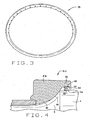
- a railcar axle A to which wheels are fitted, rotates about an axis X as the wheels roll along the rails of a railroad track.
- the axle A along with several other like axles, supports a rail car, with the weight of the rail car being transferred to the axle through bearings B.
- the axle A at each of its ends has a journal 2 which leads to a somewhat larger dust guard diameter 4 at a fillet 6. Inwardly from the dust guard diameter 4 the axle A has an even larger wheel seat to which a wheel is fitted.
- the journal 2 extends out to an end face 8 out of which threaded holes 10 open. Both the journal 2 and the dust guard diameter 4 are cylindrical and concentric, with their common center being the axis X.
- the bearing B fits around the journal 2 where it is captured between a backing ring R that bears against the fillet 6 and an end cap 12 that extends over the end face 8, yet is spaced slightly outwardly from it.
- the bearing B is separated from the backing ring R and from the end cap 12 by wear rings 14, and all are clamped tightly together with cap screws 16 which thread into the holes 10 and bear against the end cap 16.
- the bearing B includes an outer race in the form of a cup 20, an inner race in the form of two cones 22 located within the cup 16, and rolling elements in the form of tapered rollers 24 located between the cup 20 and cones 22.
- the bearing B includes a spacer 26 located between the two cones 22 to maintain a prescribed spacing between the cones 22.
- the ends of the bearing B are closed by seals 28 located between the ends of the cup 20 and the wear rings 14.
- the cones 22 fit over the journal 2 of the axle A with an interference fit, with the spacer 26 being between them.
- the cup 20 fits into an adapter which in turn fits into the truck of a railcar.
- the tapered rollers 24 lie along tapered raceways on the cup 20 and cones 22 where they are organized in two rows - one around the inboard cone 22 and the other around the outboard cone 22.
- the raceways of the two cones 22 tapered in opposite directions and so do the two raceways of the cup 20. This orients the rollers 24 such that the rollers 24 of the inboard row take thrust or axial loads in one direction, and the rollers 24 of the outboard row take thrust in the opposite direction.
- the rollers 24 of both rows transfer radial loads.
- the cones 22 have thrust ribs 30 which confine the rollers 24 to the annular space between the cup 20 and cones 22.
- the thrust rib 30 of each cone 22 leads out to back face 32, which is squared off with respect to the axis X.
- the bearing B transfers thrust loads to the axle A primarily at the back faces 32 of its cones 22.
- the thrust loads transferred through the inboard cone 22 pass to the journal 2 - or axle A - through the inboard wear ring 14 and the backing ring R which lie between the back face 32 of the inboard cone 22 and the fillet 6 on the journal 2.
- the thrust loads transferred through the outboard cone 22 pass to the journal 2 through the outboard wear ring 14, the end cap 12 and the cap screws 16.
- the end cap 32 fits over the end of the journal 2 and against the outboard wear ring 14 which in turn is against the back face 30 of the outboard cone 18.
- the cap screws 16 clamp the two cones 22 and the spacer 26 and the wear rings 14 tightly between the backing ring R and the end cap 12 and urge the backing ring R firmly against the fillet 6.
- the backing ring R As the axle A revolves it will experience some flexure, with the greatest flexure occurring at each journal 2 in the region of the back face 32 for the inboard cone 22. To prevent that flexure from imparting undue motion to the backing ring R on the fillet 6 and thereby-producing fretting at the fillet 6, the backing ring R is fitted firmly to the journal 2 around the region of the dust guard diameter 4 that lies immediately beyond the fillet 6.
- the backing ring R irrespective of the form it assumes, includes at least one element which stabilizes the backing ring R on the journal 2 from axial, radial, or circumferential movement relative to the axle A. This reduces the potential for removing the bearing B from service due to a loose backing ring R.
- the backing ring R also inhibits the seepage of moisture along the fillet 6 and thus reduces fretting corrosion between the two.
- the backing ring R may be any of several variations.
- a backing ring R-1 includes (Fig. 2) an annular body 36 that fits around the fillet 6 and further projects over the dust guard diameter 4.
- the backing ring R-1 has a stabilizing ring 38 which fits between the annular body 36 and the dust guard diameter 4 where the ring 38 remains in a state of radial compression.
- the annular body 36 is preferably formed as a steel or iron casting or forging that is machined along critical surfaces.
- One of those surfaces is an arcuate inner surface 40 that is contoured to seat against the fillet 6 in the upper or larger regions of the fillet 6.
- the inner surface 40 tapers downwardly to a conical surface 42 which is spaced slightly away from the fillet 6, and the conical surface 46, in turn, leads out to a counterbore 44 which receives the end of the inboard wear ring 14 with an interference fit.
- the opposite end of the inboard wear ring 14 bears against the back face 32 of the inboard cone 22.
- the annular body 34 At its opposite end the annular body 34 has a lip 46 which projects axially beyond the arcuate inner surface 40 and over the adjacent region of the dust guard diameter 4 on the axle A, yet is spaced from the dust guard diameter 4.
- the lip 46 contains a counterbore 48 that at one end leads away from a shoulder 50 and at its opposite end opens out of the lip 46.
- the stabilizing ring 38 fits within the counterbore 48 in the lip 46 of the annular body 36 (Figs. 2 & 3) and around the dust guard diameter 4 and stabilizes the annular body 36 on the axle A against axial, radial and circumferential movement relative to the axle A.
- the ring 38 which is preferably formed from a stainless steel or other suitable material, including some polymers, possesses a generally circular and tubular cross section and has axially directed apertures arranged at equal circumferential intervals along its inside surface to better accommodate deformation of the tubing, from which the ring 38 is formed, from straight to circular.
- the apertures are filled with a flexible substance such as a silicone sealer. Other materials such as polymers are suitable.
- the inside diameter of the stabilizer ring 38 is less than the diameter of the dust guard diameter 4, while the outside diameter is slightly greater than the diameter of the counterbore 48 in the lip 46.
- interference fits exist between the stabilizing ring 38 and both the dust guard diameter 4 and the surface of the counterbore 48.
- the stabilizing ring 38 being tubular in cross section, compresses between the two surfaces to accommodate the interference fit.
- the stabilizing ring 38 is forced into the counterbore 48 in the lip 46 of the annular body 36 with enough force to overcome the interference fit and to drive the ring 38 against the shoulder 50 at the end of the counterbore 48. Then the backing ring R-1 is advanced over the journal 2 to bring its stabilizing ring 38 to the peripheral margin of the fillet 6. At this juncture enough force is applied to the annular body 36 on the backing ring R-1 to overcome the interference fit between the stabilizing ring 38 and the dust guard diameter 4. The stabilizing ring 38 rides up onto the dust guard diameter 4 and advances until the arcuate surface 40 on the annular body 34 seats against the fillet 6. Thereafter, the wear rings 14 and bearing B are installed over the journal 2. Afterwards, the end cap 12 is placed over the end face 8 and secured to the journal 2 with the cap screws 16.
- the stabilizing ring 38 Since the stabilizing ring 38 fits rigidly compressed between the lip 46 of the annular body 36 and the dust guard diameter 4, it inhibits the lip 46 from moving radially with respect to the dust guard diameter 4. This adds a greater measure of stability to the annular body 36, and as a consequence, less movement occurs between the arcuate surface 44 on the annular body 40 and the fillet 6 against which it seats. The arcuate surface 40 and the fillet 6 experience little, if any fretting. The stabilizing ring 38 further excludes contaminants, such as water, from the fillet 6 of the axle A and the arcuate surface 40 of the annular body 36.
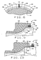
- FIG. 4 Another backing ring R-2 (Fig. 4) has an annular body 52 and a stabilizing ring 54 fitted to it.
- the annular body 52 has a lip 56 which projects over the dust guard diameter 4 where it is provided with a counterbore of sorts that includes an undercut 58 that opens toward the dust guard diameter 4.
- the ring 54 has inner and outer legs 60 and 62, respectively, which are directed axially and lie parallel to each other, the former being within the latter. It also includes an intervening section 64 which connects the two legs 60 and 62, it being joined to one end of each leg 60 and 62. The intervening section 64 from where it is attached to the legs 60 and 62, turns back into the space between the legs 60 and 62 and here doubles back upon itself so as to have a generally U-shaped configuration.
- the legs 60 and 62 and the intervening section 64 are formed integral from a material having a good measure of resiliency, spring steel or stainless steel being preferred.
- the intervening section 64 permits the outer leg 62 to displace inwardly toward the inner leg 60 without exceeding the elastic limit of the material from which the ring 54 is formed, and when the outer leg 62 is so displaced, the intervening section 64 urges the outer leg 62 outwardly away from the inner leg 60.
- the ring 54 exists in a state of radial compression between the lip 56 and the axle A.
- the inner leg 60 fits over the dust guard diameter 4 with an interference fit, while outer leg 62 fits within the undercut 58 of the lip 56.
- the intervening section 64 exists within a state of compression, thus urging the outer leg 62 outwardly against the lip 56.
- the stabilizing ring 54 is snapped into the undercut 58 in the lip 56 of the body 52. Then the body 52 and ring 54 are advanced over the journal 2, with the lip 56 and ring 54 leading. The inner leg 60 of the ring 54 rides up the fillet 6 of the journal 2 and onto dust guard diameter 4. The body 52 continues to advance until its arcuate inner surface 40 bears against the fillet 6. Here it is firmly clamped with a force exerted by the cap screws 16 and transferred through the end cap 12, wear rings 14, and bearing B.
- FIG. 5 Another backing ring R-3 (Fig. 5) has an annular body 66 and a stabilizing ring 68 fitted to the body 66.
- the body 66 resembles the body 34 for the ring R-1 in all respects, except for a lip 70 which projects over the dust guard diameter 4.
- the body 66 has a counterbore 72 which receives the dust guard diameter 4 either loosely or with an interference fit, depending on the diameter of the dust guard diameter 4.
- the counterbore 72 opens into another counterbore 74 at a shoulder 76 which is squared off with respect to the axis X, and the counterbore 74 in turn opens out of the end of the body 66.
- the stabilizing ring 68 fits tightly into the large counterbore and tightly embraces the axle A around the dust guard diameter 4.
- the ring 68 has a steel case 78, which like the ring 54 for the backing ring R-2, has parallel legs 80 and a U-shaped intervening section 82 that lies between the two legs 80.
- the legs 80 of the stabilizing ring 68 are oriented radially.
- the inside diameter of the legs 80 is slightly greater than the dust guard diameter 4.
- the stabilizing ring 68 contains a flexible core 84 which completely fills the interior of the case 78 where it is bonded to the legs 80 and intervening section 82.
- the core 84 has an inside cylindrical surface, the diameter of which is less than the diameter of the dust guard diameter 4.
- the backing ring R-3 is installed over the journal 2 with the stabilizing ring 68 received in the large counterbore 74. As the backing ring R-3 advances over the journal 2 it first encounters the fillet 6 at the core 84 of its securement ring 68. The core 84 expands and rides up over the dust guard diameter 4, snugly embracing that surface.
- the stabilizing ring 68 both stabilizes the annular body 66 and effects a seal with the dust guard diameter 4 to prevent water from seeping into the space between the fillet 6 and the arcuate inner surface 40 of the body 66.
- the case 78 may be plastically deformed by driving the legs 80 of its case 78 together with a tool fitted over the dust guard diameter 4 and brought against the exposed leg 80.
- the deformation forces the core 84 to contract axially and establish an even tighter grip on the dust guard diameter 4.
- Still another backing ring R-4 (Fig. 6) has an annular body 88 that resembles the body 34 of the backing ring R-1, differing only at its lip 90 which projects over the dust guard diameter 4.
- the lip 90 contains a counterbore 92 which receives the end of the dust guard diameter 4, either loosely or with an interference fit, depending on the diameter of the dust guard diameter 4.
- the lip 90 also contains several - perhaps four to six - threaded holes 94 which extend radially at equal circumferential intervals and pass completely through the lip 90. Each hole 94 receives a set screw 96.
- the backing ring R-4 is installed over the journal 2 with its set screws 96 backed off so that they are retracted fully into their threaded holes 94. Once the arcuate inner surface 40 seats firmly against the fillet 6, in which event the lip 90 is around the dust guard diameter 4, the screws 96 are turned down in the threaded holes 94. The inner ends of the screws 96 bear against the dust guard diameter 4, securing the body 90 firmly around the fillet 6 on the journal 2 and stabilizing it.
- FIG. 7 & 8 Another backing ring R-5 (Figs. 7 & 8) resembles the backing ring R-4 in many respects. It has a body 98 provided with lip 100 that projects over the dust guard diameter 4, yet is spaced outwardly from it. Within the lip 100 are several - perhaps four to six - jaws 102 having inside gripping surfaces 104 which lie within a cylindrical envelope having a diameter that generally conforms to the diameter of the dust guard diameter 4. In any event, the jaws 102 are arranged at equal circumferential intervals within the lip 100.
- Both the lip 100 and the jaws 102 form an integral part of the body 98, but the jaws 102 are thin and each is attached to the remainder of the body 98 at an even thinner connecting section 106, thus giving each jaw 102 a measure of flexibility which enables it to move inwardly away from the lip 100.
- the jaws 102 may be formed by machining a groove 108 in the end of the body 98, with the groove 108 separating the lip 100 and jaws 102, and then with an end mill machining slits 110 (Fig. 8) to separate the individual jaws 102.
- each jaw 104 within the lip 100 is a threaded hole 112 which extends radially completely through the lip 100.
- Each hole 112 contains a jack screw 114 which is long enough to pass through the groove 108 and bear against the jaw 102 with which its threaded hole 112 aligns.
- the backing ring R-5 is installed over the journal 2 with the jack screws 114 backed away from their jaws 102, so that a good measure of clearance exists between the jaws 102 and the set screws 114. As the arcuate inner surface 40 approaches the fillet 6, the jaws 102 ride over the end of the dust guard diameter 4 which they may grip, assuming that the dust guard diameter 4 is large enough. In any event, once the end cap 32 is installed and the body 98 of the backing ring R-5 along its inner arcuate surface 40 is seated firmly against the fillet 6 on the journal 2, the jack screws 114 are turned downwardly against the jaws 102 which underlie them. The jaws 102 flex inwardly and along their gripping surfaces 104 bear firmly against the dust guard diameter 4, thus securely positioning the backing ring R-4 around the fillet 6 and, in effect, stabilizing the annular body 98.
- FIG. 9 Yet another backing ring R-6 (Fig. 9) is very similar to the backing ring R-5 in that its annular body 118 has a lip 1,20 and jaws 122 which closely resemble the lip 102 and jaws 104, respectively, of the ring R-5.
- the lip 120 and jaws 122 are separated by an annular groove 124.
- Each jaw 122 has an arcuate gripping surface 126 which conforms to the dust guard diameter 4.
- Midway between its ends each jaw 122 has an arcuate depression 128.
- the lip 120 directly opposite the depressions 128 in the jaws 122 has like depressions 130.
- the arcuate depressions 128 and 130 are threaded and each pair contains a set screw 132.
- the set screws 132 are slightly tapered, at least at their ends which lie within the annular groove 124.
- Yet another backing ring R-7 (Fig. 10) has an annular body 136 which closely resembles the body 36 of the ring R-1, but has a somewhat different lip 138 which projects over the dust guard diameter 4.
- the lip 138 has a tapered inside surface 140 which is presented inwardly toward the dust guard diameter 4, its large end being at the end surface of the lip 138.
- the backing ring R-7 has a bushing 142 which fits between the lip 138 and the dust guard diameter 4.
- the bushing 142 has a tapered outside surface 144 which bears against the tapered inside surface 140 on the lip 138 and a cylindrical inside surface 146 which is against the dust guard diameter 4.
- the taper of the outside surface 144 corresponds to the taper of the inside surface 140 on the lip 138.
- the bushing 142 is split axially so that it can contract and expand, thus enabling its inside surface 146 to conform precisely to the dust guard diameter 4.
- the tapered bushing 142 is forced underneath the lip 138. As the bushing 142 moves under the lip 138 its tapered outside surface 144 moves against the tapered inside surface 140 on the lip 138. This causes the bushing 142 to contract and lodge tightly between the lip 138 and the dust guard diameter 4. This, in turn, positions the body 136 firmly around the fillet 6.
- the tapered bushing 142 may be installed with a tool that fits around the dust guard diameter 4, but the possibility exists that it may work loose under the flexure of the journal 2.
- the backing ring R-7 may also include retaining collar 150 that fits around the dust guard diameter 4 behind the annular body 136.
- the collar 150 contains radial set screws 152 which, when turned down, bear against the dust guard diameter 4 and fix the collar 160 firmly in place on the surface 4. It also has axial set screws 154 which, when turned down, bear against the end of the tapered bushing 142 and hold it underneath the lip 138.
- the retaining collar 150 is installed over the journal 2 and onto the dust guard diameter 4 before the body 136 is advanced over the journal 2.
- a backing ring R-8 (Fig. 11), which also resembles the backing ring R-1, has an annular body 160 that is very similar to the body 36, except that its axially directed lip 162 has a smaller counterbore 164.
- the countebore 164 which is cylindrical in configuration, opens out of the end of the lip 162 and possesses in diameter slightly greater than the diameter of the dust guard diameter 4. Both diameters are known.
- the backing ring R-8 also includes a stabilizing bushing 166 which fits around the dust guard diameter 4 and in the counterbore 164, there being an interference fit with each.
- the bushing 166 is selected from an inventory of bushings 166 having different inside and outside diameters, with the diameters of the selected bushing 166 being such that an interference fit exists between its inside surface and the dust guard diameter 4 and another interference fit exists between its outside surface and the surface of the counterbore 164.
- the selected bushing 166 is forced over the dust guard diameter 4 to a position immediately behind the fillet 6. Then the annular body 160 is advanced over the journal 2, and, after its lip 162 moves over the fillet 6, the lip 162 is forced over the bushing 166 that is already in place on the dust guard diameter 4.
- the interference fits enable the bushing 166 to position the lip 162 in a fixed position with respect to the axle A, and this reduces movement between the annular body 160 and the fillet 6. In other words, it stabilizes the annular body 160 around the fillet 6.
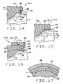
- Still another backing ring R-9 (Fig. 12) is similar in many respects to the backing ring R-4. It includes annular body 170 having a lip 172 provided with a counterbore 174 that receives the region of the dust guard diameter 4 immediately behind the fillet 6.
- the lip 172 contains several radially directed bores 176 located at equal circumferential intervals, and these bores 176 open out of its exterior surface and also into the counterbore 174.
- Each bore 176 contains a stabilizing ball 178 at its inner end, a threaded plug 180 at its outer end, and a coil-type compression, spring 182 between its ball 176 and plug 180.
- each bore 176 is reduced in diameter to prevent the spring 182 from forcing the ball 128 out of the bore 176 when the ring R-9 is detached from the journal 2, but not enough to prevent the ball 178 from projecting out of its bore 176 and into the counterbore 174.
- the ring R-10 incorporates the principle of a three-jaw chuck to stabilize it.
- the ring R-10 includes an annular body 188 having an axially directed lip 190 which projects over the dust guard diameter 4 where it is provided with a counterbore 192 that is considerably larger than the dust guard diameter 4.
- the counterbore 192 contains multiple stabilizing jaws 194 -preferably three - arranged circumferentially within the counterbore 192 in radial symmetry.
- Each jaw 194 has an arcuate gripping surface 196, the radius of which generally matches the radius of the dust guard -diameter 4.
- each jaw 194 affords a clearance between the gripping surface 196 and the dust diameter 4 when the jaw 194 is backed away toward the surface of the counterbore 192.
- Each jaw 194 also has a threaded hole 198, which extends radially in it and aligns with a radial bore 200 of lesser diameter in the lip 190.
- the multiple jaws 194 are confined to the counterbore 194 by a retaining ring 202 which is attached to the end of the lip 190 by screws that thread into the lip 190.
- the ring 202 projects radially inwardly beyond the surface of the counterbore 192.
- each jaw 194 receives a jack screw 204 having a reduced head 206 which projects into the radial bore 200 with which the screw 204 aligns.
- the head 206 at its end has a socket 208 that is configured to enable a wrench to engage the screw 204 and turn it.
- the backing ring R-10 during installation is advanced over the journal 2 with its jaws 194 retracted.
- the jaws 194 accordingly pass over the dust guard diameter 4.
- the jack screws 204 are turned with a wrench to drive the jaws 194 inwardly.
- the jaws 194 along their gripping surfaces 196 bear tightly against the dust guard diameter 4 and stabilize the annular body 168 around the fillet 6 of the journal 2.
- FIG. 14 Another backing ring R-11 (Fig. 14) has an annular body 214, which like the body 66 of the ring R-2, has a lip 216 provided with a counterbore 218 which receives the end of the dust guard diameter 4 immediately adjacent to the fillet 6 with little, if any clearance.
- the counterbore 218 opens into another counterbore 220 that opens out of the end of the lip 216, but the counterbore 218 is interrupted by an undercut 222 which opens radially inwardly toward the dust guard diameter 4.
- the longer counterbore 218 in the end of the lip 216 contains a stabilizing ring 224, the inner margin of which fits over and bears against the dust guard diameter 4, while the periphery of the ring 224 is received in the undercut 222.
- the stabilizing ring 224 consists of several steel disks 226 and elastomeric connecting elements 228 which separate the disks 226 and are bonded to them.
- the stabilizing ring 224 along it disks 226 bears against the dust guard diameter 4 and projects into the undercut 222, and when the ring 224 is so disposed, its disks 226, while being close to perpendicular with respect to the axis X, are nevertheless slightly oblique.
- the elastomeric connecting elements 228 enable the disks 226 to assume infinite angular positions oblique to the axis, and thereby accommodate slight variations in spacing between the dust guard diameter 4 and the base of the undercut 222.
- the disks of its stabilizing ring 224 lie generally perpendicular to the axis X.
- the disks 226 of the ring 224 will ride up the large end of the fillet 6 and onto the dust guard diameter 4, assuming a slightly oblique orientation in which they lodge tightly between the dust guard diameter 4 and the base of the surrounding groove 222. In this condition the ring 224 stabilizes the annular body 214 around the fillet 6.
- the backing rings R-12 (Fig. 15) somewhat resembles the backing ring R-7 without its retaining collar 150.
- the backing rings R-12 has an annular body 234 provided with a lip 236 which projects over the dust guard diameter 4 when the arcuate inner surface 44 of the body 234 is against the fillet 6 of the journal 2.
- the lip 236 contains a groove 238 where it emerges from the arcuate inner surface 44 and a tapered inside surface 240 which leads away from the groove 238, tapering outwardly toward the free end of the lip 236. Both the groove 238 and the tapered surface 240 are spaced from dust guard diameter 4 of the axle A.
- the backing ring R-12 has a tapered stabilizing ring 242 which fits tightly between the lip 236 of the annular body 234 and the dust guard diameter 4 of the axle A.
- the stabilizing ring 242 has a cylindrical inside surface 244 which bears against and conforms to the cylindrical dust guard diameter 4 of the axle
- the stabilizing ring 242 is first placed over the dust guard diameter 4 back from the position that it will eventually assume. Then the annular body 234 is advanced over the journal 2 with its lip 236 leading. Thereafter, the bearing B, wear rings 14, and end cap 32 are installed. When the cap screws 36 are tightened, the annular body 234 of the backing ring R-11 at its arcuate inside surface 44 seats firmly against the fillet 6 and the lip 236 projects over the dust guard diameter 4. Thereupon, with a tool that fits around the dust guard diameter 4, the ring 242 is forced under the lip 236.
- the backing ring R-13 uses jaws to stabilize it along the dust guard diameter 4 and in that sense is similar to the rings R-5, R-6 and R-10.
- the backing ring R-13 includes an annular body 254, the arcuate inner surface 40 of which seats against the fillet 6 of the journal 2.
- the annular body 254 supports several stabilizing jaws 256 which are attached to it at reduced connecting sections 258 and extend over and around the dust guard diameter 4.
- the jaws 256 have inside surfaces 260 which conform closely to the cylindrical dust guard diameter 4.
- the jaws 256 also have tapered outside surfaces 262 which lie in a conical envelope.
- a bushing 264 Encircling the jaws 256 is a bushing 264 having a tapered inside surface 266 which conforms to the conical envelope defined by the tapered outside surfaces 262 on the jaws 256. Indeed, the bushing 264 along its inside surface 266 bears against the outside surfaces 262 of the jaws 256.
- the backing ring R-13 also has a collar 268 which encircles the bushing 264 that is around the jaws 256 and also encircles the annular body 254 beyond the jaws 256.
- the collar 268 engages the annular body 254 along mating threads 270 and, in effect, forms a lip which projects over the dust guard diameter 4.
- the collar 268 has an inwardly directed rib 272 that lies behind the bushing 264.
- the collar 268 has several sockets 274 which open radially out of it, so that it may be engaged with a wrench and turned.
- Each of the backing rings R has an annular body that fits around the fillet 6 on the journal 2 and is provided with a lip which projects over the adjacent portion of the dust guard diameter 4. Each also has an element which cooperates with the lip to stabilize the lip and the annular body around the axle A. Being stabilized, the annular body experiences less movement in the presence of cyclic flexures in the journal 2. This reduces motion at the interface between the fillet 6 and the inner face 44 of the annular body. As a consequence, fretting is markedly reduced at the interface. All of the backing rings R fit axles having dust guard diameters 4 that are not machined to precise tolerances. Indeed, they can accommodate dust guard diameters 4 of varying diameters within limits.
- the backing rings R either effect a seal with the dust guard diameter 4 or can be modified to do so, and the seal will prevent moisture from migrating onto the fillet 6 and producing corrosion.
- the backing rings R may be utilized with other types of bearings, such as cylindrical roller bearings and spherical roller bearings. Moreover, they may be utilized with bearings that do not require the wear rings 14, but instead bear directly against the backing rings and end caps, and have seals which seal against surfaces on the bearings themselves.
Landscapes
- Engineering & Computer Science (AREA)
- General Engineering & Computer Science (AREA)
- Mechanical Engineering (AREA)
- Sealing Devices (AREA)
- Sealing Of Bearings (AREA)
- Vehicle Body Suspensions (AREA)
- Springs (AREA)
Claims (16)
- In Kombination mit einer Schienenfahrzeugachse (A), die einen Achszapfen (2) und eine größere zylindrische Fläche (4) neben dem Achszapfen aufweist, wobei der Achszapfen an einer Hohlkehle (6) in die größere zylindrische Fläche übergeht, und mit einem Lager (B), das den Achszapfen umschließt, und einer Endkappe (12), die über das Ende des Achszapfens passt, um ein axiales Herunterwandern des Lagers von dem Achszapfen zu verhindern, umfasst ein verbesserter, zwischen dem Lager und der Hohlkehle angeordneter Stützring (R1 - R13): einen ringförmigen Körper (36, 52, 66, 88, 98, 118, 136, 160, 170, 188, 214, 234, 254) mit einer Innenfläche (40), mit der er an der Hohlkehle des Achszapfens anliegt, und einer Lippe (46, 56, 70, 90, 100, 120, 138, 162, 172, 190, 216, 236, 268), die die größere zylindrische Fläche überragt, dadurch gekennzeichnet, dass der Stützring weiterhin mindestens ein stabilisierendes Element (38, 54, 68, 96, 102, 122, 142, 166, 178, 194, 226, 242, 256) aufweist, das mit der Lippe zusammenwirkt, um eine Bewegung der Lippe bezüglich der zylindrischen Fläche bei Verbiegungen des Achszapfens zu vermindern, wodurch der ringförmige Körper auf der Hohlkehle stabilisiert wird.
- Die Kombination nach Anspruch 1, dadurch gekennzeichnet, dass das stabilisierende Element (38, 54, 68, 102, 122, 142, 166, 194, 224, 242, 256) zwischen die Lippe des ringförmigen Körpers und die zylindrische Fläche der Achse passt.
- Die Kombination nach Anspruch 2, dadurch gekennzeichnet, dass das stabilisierende Element ein radial komprimierbarer Ring (38, 54, 68, 224) ist.
- Die Kombination nach Anspruch 3, dadurch gekennzeichnet, dass der stabilisierende Ring innere und äußere Schenkel (60, 62) und eine U-förmige, zwischen den Schenkeln angeordnete und endseitig mit diesen verbundene Zwischenpartie (64) aufweist, wobei der innere Schenkel an der größeren zylindrischen Fläche und der äußere Schenkel an der Lippe anliegt.
- Die Kombination nach Anspruch 3, dadurch gekennzeichnet, dass der stabilisierende Ring ein Gehäuse (78) mit im Abstand voneinander angeordneten Schenkeln (80) und einem zwischen den Schenkeln angeordneten, endseitig mit diesen verbundenen Zwischenelement (82) sowie einen elastomeren Kern (84) aufweist, der zwischen den Schenkeln angeordnet ist.
- Die Kombination nach Anspruch 2, dadurch gekennzeichnet, dass die Lippe eine konisch zulaufende, der größeren zylindrischen Fläche der Achse zugewandte Innenfläche (140, 240) aufweist und dass das stabilisierende Element ein stabilisierender Ring (142, 242) mit einer konisch zulaufenden Außenfläche (144, 246) ist, wobei der stabilisierende Ring zwischen der Lippe und der größeren zylindrischen Fläche angeordnet ist und mit seiner konisch zulaufenden Außenfläche an der konisch zulaufenden Innenfläche der Lippe anliegt.
- Die Kombination nach Anspruch 6, dadurch gekennzeichnet, dass der ringförmige Körper eine Nut (238) aufweist und die konisch zulaufende Innenfläche der Lippe abwärts in Richtung der Nut verläuft, und dass der stabilisierende Ring eine Rippe (248) am dünnen Ende seiner konisch verlaufenden Außenfläche aufweist, wobei die Rippe in die Nut in dem ringförmigen Körper eingreift.
- Die Kombination nach Anspruch 6, weiterhin umfassend einen Halterungsring (150), der stramm auf der Achse die größere zylindrische Fläche umschließend angeordnet ist, so dass er ein Herauswandern des stabilisierenden Rings aus dem Zwischenraum zwischen der Lippe und der Fläche mit dem großen Durchmesser verhindert.
- Die Kombination nach Anspruch 1, dadurch gekennzeichnet, dass das stabilisierende Element mindestens eine Madenschraube (96, 114) ist, die in die Lippe eingeschraubt ist und eine Kraft auf die Achse im Bereich der größeren zylindrischen Fläche der Achse ausübt.
- Die Kombination nach Anspruch 1, dadurch gekennzeichnet, dass die Lippe eine im Wesentlichen radial ausgerichtete Bohrung (176) aufweist, die sich in Richtung der größeren zylindrischen Fläche der Achse öffnet und dass das stabilisierende Element (178) in der Bohrung angeordnet ist; und weiterhin umfassend einen in der Bohrung angeordneten Stopfen (180) und eine in der Bohrung zwischen dem Stopfen und dem stabilisierenden Element angeordnete Feder (182), um das stabilisierende Element gegen die größere zylindrische Fläche der Achse zu pressen.
- Die Kombination nach Anspruch 1, dadurch gekennzeichnet, dass das stabilisierende Element mindestens eine Klemmbacke (102, 122, 194, 256) ist, die zwischen der Lippe und der größeren zylindrischen Fläche angeordnet ist.
- Die Kombination nach Anspruch 11, weiterhin umfassend eine Abdrückschraube (114), die in die Lippe eingeschraubt ist und im Wesentlichen radial ausgerichtet ist, um eine radial gerichtete Kraft auf die Klemmbacke auszuüben.
- Die Kombination nach Anspruch 11, weiterhin umfassend eine Abdrückschraube (132), die axial zwischen der Klemmbacke und der Lippe eingeschraubt ist, um die Klemmbacke nach innen gegen die größere zylindrische Fläche zu pressen.
- Die Kombination nach Anspruch 1, dadurch gekennzeichnet, dass das stabilisierende Element eine Buchse (142, 242) ist, die zwischen die Lippe und die größere zylindrische Fläche der Achse geklemmt ist.
- Die Kombination nach Anspruch 1, dadurch gekennzeichnet, dass das stabilisierende Element eine Mehrzahl von Scheiben (226), die schräg zwischen die Lippe und die größere zylindrische Fläche der Achse geklemmt sind, und Verbindungselemente (228), die die Scheiben derart miteinander verbinden, dass sich die Neigung der Scheiben bezüglich der Fläche größeren Durchmessers verändern kann, aufweist.
- Die Kombination nach Anspruch 1, dadurch gekennzeichnet, dass das stabilisierende Element eine von mehreren Klemmbacken (256) ist, die an dem ringförmigen Körper befestigt sind und die größere zylindrische Fläche umschließen, wobei die Klemmbacken konisch zulaufende Außenflächen (262) aufweisen; dass eine Buchse die Klemmbacken umschließt; und dass die Lippe ein Stellring (268) ist, der die Klemmbacken und die Buchse umgibt und sich axial bewegt, um die Buchse auf die konisch zulaufenden Flächen der Klemmbacken zu drücken und die Klemmbacken nach innen zu pressen.
Applications Claiming Priority (4)
| Application Number | Priority Date | Filing Date | Title |
|---|---|---|---|
| US50135303P | 2003-09-09 | 2003-09-09 | |
| US55548204P | 2004-03-23 | 2004-03-23 | |
| US10/871,147 US7219938B2 (en) | 2003-09-09 | 2004-06-18 | Backing ring for railcar axle |
| PCT/US2004/028572 WO2005025960A2 (en) | 2003-09-09 | 2004-09-03 | Backing ring for railcar axle |
Publications (2)
| Publication Number | Publication Date |
|---|---|
| EP1663752A2 EP1663752A2 (de) | 2006-06-07 |
| EP1663752B1 true EP1663752B1 (de) | 2007-11-14 |
Family
ID=34229285
Family Applications (1)
| Application Number | Title | Priority Date | Filing Date |
|---|---|---|---|
| EP04782962A Expired - Lifetime EP1663752B1 (de) | 2003-09-09 | 2004-09-03 | Stützring für schienenfahrzeugachse |
Country Status (6)
| Country | Link |
|---|---|
| US (1) | US7219938B2 (de) |
| EP (1) | EP1663752B1 (de) |
| AT (1) | ATE378226T1 (de) |
| AU (1) | AU2004272567B2 (de) |
| DE (1) | DE602004010150T2 (de) |
| WO (1) | WO2005025960A2 (de) |
Cited By (1)
| Publication number | Priority date | Publication date | Assignee | Title |
|---|---|---|---|---|
| US9150226B2 (en) | 2004-07-15 | 2015-10-06 | Amsted Rail Company, Inc. | Mounting ring |
Families Citing this family (25)
| Publication number | Priority date | Publication date | Assignee | Title |
|---|---|---|---|---|
| EP1853830A1 (de) * | 2005-03-02 | 2007-11-14 | The Timken Company | Lageranordnung mit dichtungsbildender bohrklemme |
| US7534047B2 (en) * | 2005-05-05 | 2009-05-19 | Amsted Rail Company, Inc | Journal bearing backing ring |
| US20080085069A1 (en) * | 2006-10-06 | 2008-04-10 | The Timken Company | Railroad bearing with corrosion inhibitor |
| US20100322544A1 (en) * | 2009-06-22 | 2010-12-23 | Amsted Rail Company, Inc. | Bearing assembly having a dust seal arrangement with contacting and non-contacting dust seals |
| US8226299B2 (en) * | 2009-09-14 | 2012-07-24 | Amsted Rail Company, Inc. | Roller bearing backing ring |
| UA101896C2 (ru) * | 2009-10-01 | 2013-05-13 | Амстед Рейл Компани, Инк. | Опорное кольцо железнодорожного подшипника |
| US20120195540A1 (en) * | 2011-01-28 | 2012-08-02 | Amsted Rail Company, Inc. | Roller bearing backing ring assembly |
| CA2845818C (en) | 2011-08-19 | 2016-05-24 | The Timken Company | Stabilized backing ring and stabilizing ring therefor |
| US8696212B2 (en) * | 2012-03-01 | 2014-04-15 | Amsted Rail Company, Inc. | Roller bearing backing ring assembly |
| USD727207S1 (en) * | 2012-12-18 | 2015-04-21 | Standard Car Truck Company | Railroad car axle protector |
| EP2786911B1 (de) * | 2013-04-03 | 2016-02-03 | Aktiebolaget SKF | Achslagerbaugruppe |
| DE102013009376A1 (de) * | 2013-06-05 | 2014-12-24 | Voith Patent Gmbh | Welle |
| EP3521130A1 (de) | 2013-11-26 | 2019-08-07 | Aktiebolaget SKF | Versteifungsvorrichtung, achslager, fahrzeug und verfahren zur montage und demontage solch einer versteifungsvorrichtung |
| US9534634B1 (en) * | 2014-09-30 | 2017-01-03 | Lufkin Industries, Llc | Bearing system for dynamically varying loads |
| US20160101791A1 (en) | 2014-10-08 | 2016-04-14 | Ranger Bearings LLC | Backing ring for railcar axle |
| JP6570837B2 (ja) * | 2015-01-21 | 2019-09-04 | 住友重機械工業株式会社 | 減速機 |
| US9789887B2 (en) * | 2015-05-11 | 2017-10-17 | Aktiebolaget Skf | Backing ring assembly for railcar axle bearings |
| DE102015212067B4 (de) | 2015-06-29 | 2017-11-09 | Schaeffler Technologies AG & Co. KG | Wälzlagereinheit |
| CN105128883A (zh) * | 2015-08-21 | 2015-12-09 | 洛阳Lyc轴承有限公司 | 一种铁路货车滚动轴承的后挡圈 |
| RU2714971C2 (ru) * | 2016-08-19 | 2020-02-21 | Актиеболагет Скф | Узел подкладного кольца для буксовых подшипников железнодорожного вагона |
| IT202000027065A1 (it) * | 2020-11-12 | 2022-05-12 | Italtractor | Gruppo rullo di sottocarro cingolato |
| IT202100005834A1 (it) | 2021-03-12 | 2022-09-12 | Skf Ab | Gruppo anello di appoggio ad accoppiamento universale per assili ferroviari |
| US12258052B2 (en) | 2021-06-25 | 2025-03-25 | A. Stucki Company | Universal backing ring |
| IT202100017090A1 (it) * | 2021-06-30 | 2022-12-30 | Skf Ab | Gruppo anello di appoggio con tenuta statica per assili ferroviari |
| WO2023035167A1 (zh) * | 2021-09-09 | 2023-03-16 | 舍弗勒技术股份两合公司 | 密封结构、轮毂电机驱动系统及装配方法 |
Family Cites Families (14)
| Publication number | Priority date | Publication date | Assignee | Title |
|---|---|---|---|---|
| US1401141A (en) * | 1921-12-27 | Axel danielsson | ||
| US1451690A (en) * | 1922-03-30 | 1923-04-17 | James R Fleming | Mining-car truck |
| US1533761A (en) * | 1923-09-25 | 1925-04-14 | Hugh W Sanford | Railway car |
| US2406069A (en) * | 1944-11-01 | 1946-08-20 | Walter R Freeman | Bearing |
| US3802352A (en) * | 1972-07-13 | 1974-04-09 | Timken Co | Railway truck wheel and axle set |
| US5028152A (en) * | 1990-03-21 | 1991-07-02 | The Timken Company | Machine with thermally compensated bearings |
| US5017025A (en) | 1990-04-05 | 1991-05-21 | The Timken Company | Bearing assembly for a shaft journal |
| JPH04271243A (ja) * | 1991-02-22 | 1992-09-28 | Toshiba Corp | 回転電機の軸受装置 |
| US5462367A (en) | 1994-08-18 | 1995-10-31 | The Timken Company | Compact bearing and stiffened journal |
| US5549395A (en) * | 1995-06-06 | 1996-08-27 | Brenco, Incorporated | Shaft journal bearing having improved seal wear ring |
| US5722327A (en) * | 1995-11-20 | 1998-03-03 | Amsted Industries Incorporated | Device for improving warp stiffness of a railcar truck |
| US6126321A (en) * | 1999-07-16 | 2000-10-03 | Brenco Incorporated | Shaft journal bearing and seal wear ring assembly |
| US6312161B1 (en) * | 2000-03-31 | 2001-11-06 | The Timken Company | End cap for bearing assembly |
| US20050078897A1 (en) * | 2003-10-09 | 2005-04-14 | Ming Zhang | Protection of railway axle and bearing against corrosion |
-
2004
- 2004-06-18 US US10/871,147 patent/US7219938B2/en not_active Expired - Lifetime
- 2004-09-03 DE DE602004010150T patent/DE602004010150T2/de not_active Expired - Lifetime
- 2004-09-03 EP EP04782962A patent/EP1663752B1/de not_active Expired - Lifetime
- 2004-09-03 WO PCT/US2004/028572 patent/WO2005025960A2/en not_active Ceased
- 2004-09-03 AU AU2004272567A patent/AU2004272567B2/en not_active Ceased
- 2004-09-03 AT AT04782962T patent/ATE378226T1/de not_active IP Right Cessation
Cited By (1)
| Publication number | Priority date | Publication date | Assignee | Title |
|---|---|---|---|---|
| US9150226B2 (en) | 2004-07-15 | 2015-10-06 | Amsted Rail Company, Inc. | Mounting ring |
Also Published As
| Publication number | Publication date |
|---|---|
| US7219938B2 (en) | 2007-05-22 |
| WO2005025960A3 (en) | 2006-06-29 |
| AU2004272567B2 (en) | 2011-07-14 |
| US20050052043A1 (en) | 2005-03-10 |
| EP1663752A2 (de) | 2006-06-07 |
| ATE378226T1 (de) | 2007-11-15 |
| AU2004272567A1 (en) | 2005-03-24 |
| DE602004010150T2 (de) | 2008-10-02 |
| WO2005025960A2 (en) | 2005-03-24 |
| DE602004010150D1 (de) | 2007-12-27 |
Similar Documents
| Publication | Publication Date | Title |
|---|---|---|
| EP1663752B1 (de) | Stützring für schienenfahrzeugachse | |
| US9127769B2 (en) | Stabilized backing ring and stabilizing ring therefor | |
| US5494358A (en) | Package bearing | |
| AU758468B2 (en) | Shaft journal bearing and seal wear ring assembly | |
| US8465211B2 (en) | Compact wheel end and corner module | |
| MX2012010486A (es) | Ensamble de anillo de soporte de cojinetes de rodillo. | |
| CA1114436A (en) | Wheel mounting and tapered roller bearing therefor | |
| US20090123099A1 (en) | Bearing Assembly With a Seal-Forming Bore Clip | |
| ZA201005920B (en) | Railway car bearing seal | |
| AU2010200831A1 (en) | Roller bearing backing ring | |
| US20080085069A1 (en) | Railroad bearing with corrosion inhibitor | |
| JPH1191309A (ja) | 車輪マウント | |
| US20080252030A1 (en) | Vehicle corner module | |
| CA1167894A (en) | Antifriction bearing with removable seal means | |
| CN101309804A (zh) | 成套轴承组件及其装配方法 | |
| MX2011002282A (es) | Sello de cojinete para ferrocarril. | |
| US20090154856A1 (en) | Wheel Support Bearing Assembly and Method of Manufacturing the Same | |
| WO2005011903A2 (en) | Method and apparatus for reducing the run-out | |
| CN113119655B (zh) | 具有径向和轴向位移限制器的轮毂轴承单元 | |
| WO2002038428A1 (en) | Stabilized seal wear ring | |
| JP6977749B2 (ja) | ハブユニット軸受及びその製造方法、揺動かしめ装置、車両及びその製造方法 | |
| JP4948063B2 (ja) | 車輪用軸受装置 | |
| JP2005119383A (ja) | 車輪用軸受装置 | |
| KR20200115519A (ko) | 시일의 조립 장치 및 시일의 조립 방법 | |
| JP2022134633A (ja) | 車輪用軸受装置 |
Legal Events
| Date | Code | Title | Description |
|---|---|---|---|
| PUAI | Public reference made under article 153(3) epc to a published international application that has entered the european phase |
Free format text: ORIGINAL CODE: 0009012 |
|
| 17P | Request for examination filed |
Effective date: 20060327 |
|
| AK | Designated contracting states |
Kind code of ref document: A2 Designated state(s): AT BE BG CH CY CZ DE DK EE ES FI FR GB GR HU IE IT LI LU MC NL PL PT RO SE SI SK TR |
|
| AX | Request for extension of the european patent |
Extension state: AL HR LT LV MK |
|
| PUAK | Availability of information related to the publication of the international search report |
Free format text: ORIGINAL CODE: 0009015 |
|
| RIC1 | Information provided on ipc code assigned before grant |
Ipc: B61F 15/22 20060101AFI20060727BHEP |
|
| 17Q | First examination report despatched |
Effective date: 20061108 |
|
| DAX | Request for extension of the european patent (deleted) | ||
| GRAP | Despatch of communication of intention to grant a patent |
Free format text: ORIGINAL CODE: EPIDOSNIGR1 |
|
| GRAS | Grant fee paid |
Free format text: ORIGINAL CODE: EPIDOSNIGR3 |
|
| GRAA | (expected) grant |
Free format text: ORIGINAL CODE: 0009210 |
|
| AK | Designated contracting states |
Kind code of ref document: B1 Designated state(s): AT BE BG CH CY CZ DE DK EE ES FI FR GB GR HU IE IT LI LU MC NL PL PT RO SE SI SK TR |
|
| REG | Reference to a national code |
Ref country code: GB Ref legal event code: FG4D |
|
| REG | Reference to a national code |
Ref country code: CH Ref legal event code: EP |
|
| REG | Reference to a national code |
Ref country code: IE Ref legal event code: FG4D |
|
| REF | Corresponds to: |
Ref document number: 602004010150 Country of ref document: DE Date of ref document: 20071227 Kind code of ref document: P |
|
| REG | Reference to a national code |
Ref country code: SE Ref legal event code: TRGR |
|
| PG25 | Lapsed in a contracting state [announced via postgrant information from national office to epo] |
Ref country code: NL Free format text: LAPSE BECAUSE OF FAILURE TO SUBMIT A TRANSLATION OF THE DESCRIPTION OR TO PAY THE FEE WITHIN THE PRESCRIBED TIME-LIMIT Effective date: 20071114 Ref country code: ES Free format text: LAPSE BECAUSE OF FAILURE TO SUBMIT A TRANSLATION OF THE DESCRIPTION OR TO PAY THE FEE WITHIN THE PRESCRIBED TIME-LIMIT Effective date: 20080225 Ref country code: CH Free format text: LAPSE BECAUSE OF FAILURE TO SUBMIT A TRANSLATION OF THE DESCRIPTION OR TO PAY THE FEE WITHIN THE PRESCRIBED TIME-LIMIT Effective date: 20071114 Ref country code: LI Free format text: LAPSE BECAUSE OF FAILURE TO SUBMIT A TRANSLATION OF THE DESCRIPTION OR TO PAY THE FEE WITHIN THE PRESCRIBED TIME-LIMIT Effective date: 20071114 |
|
| NLV1 | Nl: lapsed or annulled due to failure to fulfill the requirements of art. 29p and 29m of the patents act | ||
| PG25 | Lapsed in a contracting state [announced via postgrant information from national office to epo] |
Ref country code: SI Free format text: LAPSE BECAUSE OF FAILURE TO SUBMIT A TRANSLATION OF THE DESCRIPTION OR TO PAY THE FEE WITHIN THE PRESCRIBED TIME-LIMIT Effective date: 20071114 Ref country code: FI Free format text: LAPSE BECAUSE OF FAILURE TO SUBMIT A TRANSLATION OF THE DESCRIPTION OR TO PAY THE FEE WITHIN THE PRESCRIBED TIME-LIMIT Effective date: 20071114 Ref country code: PL Free format text: LAPSE BECAUSE OF FAILURE TO SUBMIT A TRANSLATION OF THE DESCRIPTION OR TO PAY THE FEE WITHIN THE PRESCRIBED TIME-LIMIT Effective date: 20071114 Ref country code: BG Free format text: LAPSE BECAUSE OF FAILURE TO SUBMIT A TRANSLATION OF THE DESCRIPTION OR TO PAY THE FEE WITHIN THE PRESCRIBED TIME-LIMIT Effective date: 20080214 |
|
| REG | Reference to a national code |
Ref country code: CH Ref legal event code: PL |
|
| PG25 | Lapsed in a contracting state [announced via postgrant information from national office to epo] |
Ref country code: AT Free format text: LAPSE BECAUSE OF FAILURE TO SUBMIT A TRANSLATION OF THE DESCRIPTION OR TO PAY THE FEE WITHIN THE PRESCRIBED TIME-LIMIT Effective date: 20071114 |
|
| ET | Fr: translation filed | ||
| PG25 | Lapsed in a contracting state [announced via postgrant information from national office to epo] |
Ref country code: CZ Free format text: LAPSE BECAUSE OF FAILURE TO SUBMIT A TRANSLATION OF THE DESCRIPTION OR TO PAY THE FEE WITHIN THE PRESCRIBED TIME-LIMIT Effective date: 20071114 Ref country code: DK Free format text: LAPSE BECAUSE OF FAILURE TO SUBMIT A TRANSLATION OF THE DESCRIPTION OR TO PAY THE FEE WITHIN THE PRESCRIBED TIME-LIMIT Effective date: 20071114 |
|
| PG25 | Lapsed in a contracting state [announced via postgrant information from national office to epo] |
Ref country code: SK Free format text: LAPSE BECAUSE OF FAILURE TO SUBMIT A TRANSLATION OF THE DESCRIPTION OR TO PAY THE FEE WITHIN THE PRESCRIBED TIME-LIMIT Effective date: 20071114 Ref country code: BE Free format text: LAPSE BECAUSE OF FAILURE TO SUBMIT A TRANSLATION OF THE DESCRIPTION OR TO PAY THE FEE WITHIN THE PRESCRIBED TIME-LIMIT Effective date: 20071114 Ref country code: RO Free format text: LAPSE BECAUSE OF FAILURE TO SUBMIT A TRANSLATION OF THE DESCRIPTION OR TO PAY THE FEE WITHIN THE PRESCRIBED TIME-LIMIT Effective date: 20071114 |
|
| PLBE | No opposition filed within time limit |
Free format text: ORIGINAL CODE: 0009261 |
|
| STAA | Information on the status of an ep patent application or granted ep patent |
Free format text: STATUS: NO OPPOSITION FILED WITHIN TIME LIMIT |
|
| PG25 | Lapsed in a contracting state [announced via postgrant information from national office to epo] |
Ref country code: PT Free format text: LAPSE BECAUSE OF FAILURE TO SUBMIT A TRANSLATION OF THE DESCRIPTION OR TO PAY THE FEE WITHIN THE PRESCRIBED TIME-LIMIT Effective date: 20080414 |
|
| 26N | No opposition filed |
Effective date: 20080815 |
|
| PG25 | Lapsed in a contracting state [announced via postgrant information from national office to epo] |
Ref country code: GR Free format text: LAPSE BECAUSE OF FAILURE TO SUBMIT A TRANSLATION OF THE DESCRIPTION OR TO PAY THE FEE WITHIN THE PRESCRIBED TIME-LIMIT Effective date: 20080215 |
|
| PG25 | Lapsed in a contracting state [announced via postgrant information from national office to epo] |
Ref country code: EE Free format text: LAPSE BECAUSE OF FAILURE TO SUBMIT A TRANSLATION OF THE DESCRIPTION OR TO PAY THE FEE WITHIN THE PRESCRIBED TIME-LIMIT Effective date: 20071114 Ref country code: MC Free format text: LAPSE BECAUSE OF NON-PAYMENT OF DUE FEES Effective date: 20080930 |
|
| PG25 | Lapsed in a contracting state [announced via postgrant information from national office to epo] |
Ref country code: IE Free format text: LAPSE BECAUSE OF NON-PAYMENT OF DUE FEES Effective date: 20080903 Ref country code: CY Free format text: LAPSE BECAUSE OF FAILURE TO SUBMIT A TRANSLATION OF THE DESCRIPTION OR TO PAY THE FEE WITHIN THE PRESCRIBED TIME-LIMIT Effective date: 20071114 |
|
| PG25 | Lapsed in a contracting state [announced via postgrant information from national office to epo] |
Ref country code: LU Free format text: LAPSE BECAUSE OF NON-PAYMENT OF DUE FEES Effective date: 20080903 Ref country code: HU Free format text: LAPSE BECAUSE OF FAILURE TO SUBMIT A TRANSLATION OF THE DESCRIPTION OR TO PAY THE FEE WITHIN THE PRESCRIBED TIME-LIMIT Effective date: 20080515 |
|
| PG25 | Lapsed in a contracting state [announced via postgrant information from national office to epo] |
Ref country code: TR Free format text: LAPSE BECAUSE OF FAILURE TO SUBMIT A TRANSLATION OF THE DESCRIPTION OR TO PAY THE FEE WITHIN THE PRESCRIBED TIME-LIMIT Effective date: 20071114 |
|
| PG25 | Lapsed in a contracting state [announced via postgrant information from national office to epo] |
Ref country code: IT Free format text: LAPSE BECAUSE OF NON-PAYMENT OF DUE FEES Effective date: 20080930 |
|
| REG | Reference to a national code |
Ref country code: FR Ref legal event code: PLFP Year of fee payment: 13 |
|
| REG | Reference to a national code |
Ref country code: FR Ref legal event code: PLFP Year of fee payment: 14 |
|
| REG | Reference to a national code |
Ref country code: FR Ref legal event code: PLFP Year of fee payment: 15 |
|
| PGFP | Annual fee paid to national office [announced via postgrant information from national office to epo] |
Ref country code: DE Payment date: 20190918 Year of fee payment: 16 Ref country code: SE Payment date: 20190918 Year of fee payment: 16 Ref country code: FR Payment date: 20190926 Year of fee payment: 16 |
|
| PGFP | Annual fee paid to national office [announced via postgrant information from national office to epo] |
Ref country code: GB Payment date: 20190920 Year of fee payment: 16 |
|
| REG | Reference to a national code |
Ref country code: DE Ref legal event code: R119 Ref document number: 602004010150 Country of ref document: DE |
|
| GBPC | Gb: european patent ceased through non-payment of renewal fee |
Effective date: 20200903 |
|
| PG25 | Lapsed in a contracting state [announced via postgrant information from national office to epo] |
Ref country code: FR Free format text: LAPSE BECAUSE OF NON-PAYMENT OF DUE FEES Effective date: 20200930 Ref country code: DE Free format text: LAPSE BECAUSE OF NON-PAYMENT OF DUE FEES Effective date: 20210401 |
|
| PG25 | Lapsed in a contracting state [announced via postgrant information from national office to epo] |
Ref country code: SE Free format text: LAPSE BECAUSE OF NON-PAYMENT OF DUE FEES Effective date: 20200904 Ref country code: GB Free format text: LAPSE BECAUSE OF NON-PAYMENT OF DUE FEES Effective date: 20200903 |
|
| REG | Reference to a national code |
Ref country code: SE Ref legal event code: EUG |