US9534634B1 - Bearing system for dynamically varying loads - Google Patents

Bearing system for dynamically varying loads Download PDF

Info

Publication number
US9534634B1
US9534634B1 US14/503,283 US201414503283A US9534634B1 US 9534634 B1 US9534634 B1 US 9534634B1 US 201414503283 A US201414503283 A US 201414503283A US 9534634 B1 US9534634 B1 US 9534634B1
Authority
US
United States
Prior art keywords
bearing
component
assemblies
interference fit
stationary
Prior art date
Legal status (The legal status is an assumption and is not a legal conclusion. Google has not performed a legal analysis and makes no representation as to the accuracy of the status listed.)
Active, expires
Application number
US14/503,283
Inventor
Montana Z. Adams
David W. Toney
Current Assignee (The listed assignees may be inaccurate. Google has not performed a legal analysis and makes no representation or warranty as to the accuracy of the list.)
Lufkin Gears LLC
Original Assignee
Lufkin Industries LLC
Priority date (The priority date is an assumption and is not a legal conclusion. Google has not performed a legal analysis and makes no representation as to the accuracy of the date listed.)
Filing date
Publication date
Application filed by Lufkin Industries LLC filed Critical Lufkin Industries LLC
Priority to US14/503,283 priority Critical patent/US9534634B1/en
Assigned to LUFKIN INDUSTRIES, LLC reassignment LUFKIN INDUSTRIES, LLC ASSIGNMENT OF ASSIGNORS INTEREST (SEE DOCUMENT FOR DETAILS). Assignors: ADAMS, MONTANA Z., TONEY, DAVID W.
Priority to RU2017109395A priority patent/RU2699594C2/en
Priority to CA2962405A priority patent/CA2962405C/en
Priority to PCT/US2015/049889 priority patent/WO2016053602A1/en
Application granted granted Critical
Publication of US9534634B1 publication Critical patent/US9534634B1/en
Assigned to LUFKIN GEARS LLC reassignment LUFKIN GEARS LLC CHANGE OF NAME (SEE DOCUMENT FOR DETAILS). Assignors: LUFKIN INDUSTRIES, LLC
Active legal-status Critical Current
Adjusted expiration legal-status Critical

Links

Images

Classifications

    • FMECHANICAL ENGINEERING; LIGHTING; HEATING; WEAPONS; BLASTING
    • F16ENGINEERING ELEMENTS AND UNITS; GENERAL MEASURES FOR PRODUCING AND MAINTAINING EFFECTIVE FUNCTIONING OF MACHINES OR INSTALLATIONS; THERMAL INSULATION IN GENERAL
    • F16CSHAFTS; FLEXIBLE SHAFTS; ELEMENTS OR CRANKSHAFT MECHANISMS; ROTARY BODIES OTHER THAN GEARING ELEMENTS; BEARINGS
    • F16C33/00Parts of bearings; Special methods for making bearings or parts thereof
    • F16C33/30Parts of ball or roller bearings
    • F16C33/66Special parts or details in view of lubrication
    • F16C33/6637Special parts or details in view of lubrication with liquid lubricant
    • F16C33/6681Details of distribution or circulation inside the bearing, e.g. grooves on the cage or passages in the rolling elements
    • FMECHANICAL ENGINEERING; LIGHTING; HEATING; WEAPONS; BLASTING
    • F16ENGINEERING ELEMENTS AND UNITS; GENERAL MEASURES FOR PRODUCING AND MAINTAINING EFFECTIVE FUNCTIONING OF MACHINES OR INSTALLATIONS; THERMAL INSULATION IN GENERAL
    • F16CSHAFTS; FLEXIBLE SHAFTS; ELEMENTS OR CRANKSHAFT MECHANISMS; ROTARY BODIES OTHER THAN GEARING ELEMENTS; BEARINGS
    • F16C13/00Rolls, drums, discs, or the like; Bearings or mountings therefor
    • F16C13/02Bearings
    • F16C13/022Bearings supporting a hollow roll mantle rotating with respect to a yoke or axle
    • FMECHANICAL ENGINEERING; LIGHTING; HEATING; WEAPONS; BLASTING
    • F16ENGINEERING ELEMENTS AND UNITS; GENERAL MEASURES FOR PRODUCING AND MAINTAINING EFFECTIVE FUNCTIONING OF MACHINES OR INSTALLATIONS; THERMAL INSULATION IN GENERAL
    • F16CSHAFTS; FLEXIBLE SHAFTS; ELEMENTS OR CRANKSHAFT MECHANISMS; ROTARY BODIES OTHER THAN GEARING ELEMENTS; BEARINGS
    • F16C19/00Bearings with rolling contact, for exclusively rotary movement
    • F16C19/22Bearings with rolling contact, for exclusively rotary movement with bearing rollers essentially of the same size in one or more circular rows, e.g. needle bearings
    • F16C19/24Bearings with rolling contact, for exclusively rotary movement with bearing rollers essentially of the same size in one or more circular rows, e.g. needle bearings for radial load mainly
    • F16C19/28Bearings with rolling contact, for exclusively rotary movement with bearing rollers essentially of the same size in one or more circular rows, e.g. needle bearings for radial load mainly with two or more rows of rollers
    • FMECHANICAL ENGINEERING; LIGHTING; HEATING; WEAPONS; BLASTING
    • F16ENGINEERING ELEMENTS AND UNITS; GENERAL MEASURES FOR PRODUCING AND MAINTAINING EFFECTIVE FUNCTIONING OF MACHINES OR INSTALLATIONS; THERMAL INSULATION IN GENERAL
    • F16CSHAFTS; FLEXIBLE SHAFTS; ELEMENTS OR CRANKSHAFT MECHANISMS; ROTARY BODIES OTHER THAN GEARING ELEMENTS; BEARINGS
    • F16C19/00Bearings with rolling contact, for exclusively rotary movement
    • F16C19/22Bearings with rolling contact, for exclusively rotary movement with bearing rollers essentially of the same size in one or more circular rows, e.g. needle bearings
    • F16C19/34Bearings with rolling contact, for exclusively rotary movement with bearing rollers essentially of the same size in one or more circular rows, e.g. needle bearings for both radial and axial load
    • F16C19/38Bearings with rolling contact, for exclusively rotary movement with bearing rollers essentially of the same size in one or more circular rows, e.g. needle bearings for both radial and axial load with two or more rows of rollers
    • F16C19/383Bearings with rolling contact, for exclusively rotary movement with bearing rollers essentially of the same size in one or more circular rows, e.g. needle bearings for both radial and axial load with two or more rows of rollers with tapered rollers, i.e. rollers having essentially the shape of a truncated cone
    • F16C19/385Bearings with rolling contact, for exclusively rotary movement with bearing rollers essentially of the same size in one or more circular rows, e.g. needle bearings for both radial and axial load with two or more rows of rollers with tapered rollers, i.e. rollers having essentially the shape of a truncated cone with two rows, i.e. double-row tapered roller bearings
    • FMECHANICAL ENGINEERING; LIGHTING; HEATING; WEAPONS; BLASTING
    • F16ENGINEERING ELEMENTS AND UNITS; GENERAL MEASURES FOR PRODUCING AND MAINTAINING EFFECTIVE FUNCTIONING OF MACHINES OR INSTALLATIONS; THERMAL INSULATION IN GENERAL
    • F16CSHAFTS; FLEXIBLE SHAFTS; ELEMENTS OR CRANKSHAFT MECHANISMS; ROTARY BODIES OTHER THAN GEARING ELEMENTS; BEARINGS
    • F16C19/00Bearings with rolling contact, for exclusively rotary movement
    • F16C19/54Systems consisting of a plurality of bearings with rolling friction
    • F16C19/541Systems consisting of juxtaposed rolling bearings including at least one angular contact bearing
    • FMECHANICAL ENGINEERING; LIGHTING; HEATING; WEAPONS; BLASTING
    • F16ENGINEERING ELEMENTS AND UNITS; GENERAL MEASURES FOR PRODUCING AND MAINTAINING EFFECTIVE FUNCTIONING OF MACHINES OR INSTALLATIONS; THERMAL INSULATION IN GENERAL
    • F16CSHAFTS; FLEXIBLE SHAFTS; ELEMENTS OR CRANKSHAFT MECHANISMS; ROTARY BODIES OTHER THAN GEARING ELEMENTS; BEARINGS
    • F16C19/00Bearings with rolling contact, for exclusively rotary movement
    • F16C19/54Systems consisting of a plurality of bearings with rolling friction
    • F16C19/546Systems with spaced apart rolling bearings including at least one angular contact bearing
    • F16C19/547Systems with spaced apart rolling bearings including at least one angular contact bearing with two angular contact rolling bearings
    • FMECHANICAL ENGINEERING; LIGHTING; HEATING; WEAPONS; BLASTING
    • F16ENGINEERING ELEMENTS AND UNITS; GENERAL MEASURES FOR PRODUCING AND MAINTAINING EFFECTIVE FUNCTIONING OF MACHINES OR INSTALLATIONS; THERMAL INSULATION IN GENERAL
    • F16CSHAFTS; FLEXIBLE SHAFTS; ELEMENTS OR CRANKSHAFT MECHANISMS; ROTARY BODIES OTHER THAN GEARING ELEMENTS; BEARINGS
    • F16C33/00Parts of bearings; Special methods for making bearings or parts thereof
    • F16C33/30Parts of ball or roller bearings
    • F16C33/66Special parts or details in view of lubrication
    • F16C33/6603Special parts or details in view of lubrication with grease as lubricant
    • F16C33/6622Details of supply and/or removal of the grease, e.g. purging grease
    • FMECHANICAL ENGINEERING; LIGHTING; HEATING; WEAPONS; BLASTING
    • F16ENGINEERING ELEMENTS AND UNITS; GENERAL MEASURES FOR PRODUCING AND MAINTAINING EFFECTIVE FUNCTIONING OF MACHINES OR INSTALLATIONS; THERMAL INSULATION IN GENERAL
    • F16CSHAFTS; FLEXIBLE SHAFTS; ELEMENTS OR CRANKSHAFT MECHANISMS; ROTARY BODIES OTHER THAN GEARING ELEMENTS; BEARINGS
    • F16C33/00Parts of bearings; Special methods for making bearings or parts thereof
    • F16C33/30Parts of ball or roller bearings
    • F16C33/66Special parts or details in view of lubrication
    • F16C33/6603Special parts or details in view of lubrication with grease as lubricant
    • F16C33/6629Details of distribution or circulation inside the bearing, e.g. grooves on the cage or passages in the rolling elements
    • FMECHANICAL ENGINEERING; LIGHTING; HEATING; WEAPONS; BLASTING
    • F16ENGINEERING ELEMENTS AND UNITS; GENERAL MEASURES FOR PRODUCING AND MAINTAINING EFFECTIVE FUNCTIONING OF MACHINES OR INSTALLATIONS; THERMAL INSULATION IN GENERAL
    • F16CSHAFTS; FLEXIBLE SHAFTS; ELEMENTS OR CRANKSHAFT MECHANISMS; ROTARY BODIES OTHER THAN GEARING ELEMENTS; BEARINGS
    • F16C33/00Parts of bearings; Special methods for making bearings or parts thereof
    • F16C33/30Parts of ball or roller bearings
    • F16C33/66Special parts or details in view of lubrication
    • F16C33/6637Special parts or details in view of lubrication with liquid lubricant
    • F16C33/664Retaining the liquid in or near the bearing
    • F16C33/6651Retaining the liquid in or near the bearing in recesses or cavities provided in retainers, races or rolling elements
    • FMECHANICAL ENGINEERING; LIGHTING; HEATING; WEAPONS; BLASTING
    • F16ENGINEERING ELEMENTS AND UNITS; GENERAL MEASURES FOR PRODUCING AND MAINTAINING EFFECTIVE FUNCTIONING OF MACHINES OR INSTALLATIONS; THERMAL INSULATION IN GENERAL
    • F16CSHAFTS; FLEXIBLE SHAFTS; ELEMENTS OR CRANKSHAFT MECHANISMS; ROTARY BODIES OTHER THAN GEARING ELEMENTS; BEARINGS
    • F16C35/00Rigid support of bearing units; Housings, e.g. caps, covers
    • F16C35/04Rigid support of bearing units; Housings, e.g. caps, covers in the case of ball or roller bearings
    • F16C35/06Mounting or dismounting of ball or roller bearings; Fixing them onto shaft or in housing
    • FMECHANICAL ENGINEERING; LIGHTING; HEATING; WEAPONS; BLASTING
    • F16ENGINEERING ELEMENTS AND UNITS; GENERAL MEASURES FOR PRODUCING AND MAINTAINING EFFECTIVE FUNCTIONING OF MACHINES OR INSTALLATIONS; THERMAL INSULATION IN GENERAL
    • F16CSHAFTS; FLEXIBLE SHAFTS; ELEMENTS OR CRANKSHAFT MECHANISMS; ROTARY BODIES OTHER THAN GEARING ELEMENTS; BEARINGS
    • F16C19/00Bearings with rolling contact, for exclusively rotary movement
    • F16C19/22Bearings with rolling contact, for exclusively rotary movement with bearing rollers essentially of the same size in one or more circular rows, e.g. needle bearings
    • F16C19/34Bearings with rolling contact, for exclusively rotary movement with bearing rollers essentially of the same size in one or more circular rows, e.g. needle bearings for both radial and axial load
    • F16C19/38Bearings with rolling contact, for exclusively rotary movement with bearing rollers essentially of the same size in one or more circular rows, e.g. needle bearings for both radial and axial load with two or more rows of rollers
    • F16C19/383Bearings with rolling contact, for exclusively rotary movement with bearing rollers essentially of the same size in one or more circular rows, e.g. needle bearings for both radial and axial load with two or more rows of rollers with tapered rollers, i.e. rollers having essentially the shape of a truncated cone
    • F16C19/385Bearings with rolling contact, for exclusively rotary movement with bearing rollers essentially of the same size in one or more circular rows, e.g. needle bearings for both radial and axial load with two or more rows of rollers with tapered rollers, i.e. rollers having essentially the shape of a truncated cone with two rows, i.e. double-row tapered roller bearings
    • F16C19/386Bearings with rolling contact, for exclusively rotary movement with bearing rollers essentially of the same size in one or more circular rows, e.g. needle bearings for both radial and axial load with two or more rows of rollers with tapered rollers, i.e. rollers having essentially the shape of a truncated cone with two rows, i.e. double-row tapered roller bearings in O-arrangement
    • FMECHANICAL ENGINEERING; LIGHTING; HEATING; WEAPONS; BLASTING
    • F16ENGINEERING ELEMENTS AND UNITS; GENERAL MEASURES FOR PRODUCING AND MAINTAINING EFFECTIVE FUNCTIONING OF MACHINES OR INSTALLATIONS; THERMAL INSULATION IN GENERAL
    • F16CSHAFTS; FLEXIBLE SHAFTS; ELEMENTS OR CRANKSHAFT MECHANISMS; ROTARY BODIES OTHER THAN GEARING ELEMENTS; BEARINGS
    • F16C19/00Bearings with rolling contact, for exclusively rotary movement
    • F16C19/54Systems consisting of a plurality of bearings with rolling friction
    • F16C19/541Systems consisting of juxtaposed rolling bearings including at least one angular contact bearing
    • F16C19/542Systems consisting of juxtaposed rolling bearings including at least one angular contact bearing with two rolling bearings with angular contact
    • F16C19/543Systems consisting of juxtaposed rolling bearings including at least one angular contact bearing with two rolling bearings with angular contact in O-arrangement
    • FMECHANICAL ENGINEERING; LIGHTING; HEATING; WEAPONS; BLASTING
    • F16ENGINEERING ELEMENTS AND UNITS; GENERAL MEASURES FOR PRODUCING AND MAINTAINING EFFECTIVE FUNCTIONING OF MACHINES OR INSTALLATIONS; THERMAL INSULATION IN GENERAL
    • F16CSHAFTS; FLEXIBLE SHAFTS; ELEMENTS OR CRANKSHAFT MECHANISMS; ROTARY BODIES OTHER THAN GEARING ELEMENTS; BEARINGS
    • F16C2226/00Joining parts; Fastening; Assembling or mounting parts
    • F16C2226/10Force connections, e.g. clamping
    • F16C2226/12Force connections, e.g. clamping by press-fit, e.g. plug-in
    • FMECHANICAL ENGINEERING; LIGHTING; HEATING; WEAPONS; BLASTING
    • F16ENGINEERING ELEMENTS AND UNITS; GENERAL MEASURES FOR PRODUCING AND MAINTAINING EFFECTIVE FUNCTIONING OF MACHINES OR INSTALLATIONS; THERMAL INSULATION IN GENERAL
    • F16CSHAFTS; FLEXIBLE SHAFTS; ELEMENTS OR CRANKSHAFT MECHANISMS; ROTARY BODIES OTHER THAN GEARING ELEMENTS; BEARINGS
    • F16C2240/00Specified values or numerical ranges of parameters; Relations between them
    • F16C2240/40Linear dimensions, e.g. length, radius, thickness, gap
    • F16C2240/56Tolerances; Accuracy of linear dimensions
    • FMECHANICAL ENGINEERING; LIGHTING; HEATING; WEAPONS; BLASTING
    • F16ENGINEERING ELEMENTS AND UNITS; GENERAL MEASURES FOR PRODUCING AND MAINTAINING EFFECTIVE FUNCTIONING OF MACHINES OR INSTALLATIONS; THERMAL INSULATION IN GENERAL
    • F16CSHAFTS; FLEXIBLE SHAFTS; ELEMENTS OR CRANKSHAFT MECHANISMS; ROTARY BODIES OTHER THAN GEARING ELEMENTS; BEARINGS
    • F16C2352/00Apparatus for drilling
    • FMECHANICAL ENGINEERING; LIGHTING; HEATING; WEAPONS; BLASTING
    • F16ENGINEERING ELEMENTS AND UNITS; GENERAL MEASURES FOR PRODUCING AND MAINTAINING EFFECTIVE FUNCTIONING OF MACHINES OR INSTALLATIONS; THERMAL INSULATION IN GENERAL
    • F16CSHAFTS; FLEXIBLE SHAFTS; ELEMENTS OR CRANKSHAFT MECHANISMS; ROTARY BODIES OTHER THAN GEARING ELEMENTS; BEARINGS
    • F16C33/00Parts of bearings; Special methods for making bearings or parts thereof
    • F16C33/72Sealings
    • F16C33/76Sealings of ball or roller bearings
    • F16C33/78Sealings of ball or roller bearings with a diaphragm, disc, or ring, with or without resilient members
    • F16C33/7803Sealings of ball or roller bearings with a diaphragm, disc, or ring, with or without resilient members suited for particular types of rolling bearings
    • F16C33/7813Sealings of ball or roller bearings with a diaphragm, disc, or ring, with or without resilient members suited for particular types of rolling bearings for tapered roller bearings

Definitions

  • the inventions disclosed and taught herein relate generally to bearing systems; and more specifically relate to bearing systems for dynamically varying loads.
  • a wide variety of rotating equipment utilizes one or more rolling assemblies to react loads as well as facilitate rotational motion.
  • railroad car wheels may be considered rolling assemblies and use bearing systems to react the load of the railcar and to facilitate rotational motion.
  • Low profile pumping units such as those available from Lufkin Industries, LLC, utilize rolling assemblies with bearing assemblies to react loads and facilitate rotation.
  • a bearing system comprises a plurality of bearing assemblies, each assembly being open at at least one end to allow the flow of lubrication through the assemblies; a first component having bearing areas for each of the bearing assemblies, and each bearing area being separated from an adjacent bearing area by a raised portion; each bearing assembly having a first portion configured to interference fit onto its first component bearing area, and a second portion of each bearing assembly contacting the raised portion of the first component; at least one retainer disposed adjacent an end of the first component and adjacent a bearing assembly; a lubrication pathway defined by the at least one retainer, the bearing assemblies and the first component; is and a second component configured to interference fit on to a third portion of each of the bearing assemblies.
  • a bearing system comprises at least one bearing having a first portion configured to interference fit with a first component, and a second portion of the at least one bearing assembly configured to interference fit with a second component; a first component configured to interference fit with the first portion of the at least one bearing assembly; a second component configured to interference fit with the second portion of the at least one bearing assembly; the first component is configured to be stationary and the second component is configured to be rotatable, or the first component is configured be rotatable and the second component is configured to be stationary; and the interference overlap of the interference fit between the bearing portion and stationary component is greater than the interference overlap of the interference fit between the other bearing portion and rotating component.
  • FIG. 1 illustrates a low profile pumping unit that experiences dynamically varying loads during operation and which utilizes bearing systems of the present invention.
  • FIGS. 2A and 2B illustrate a roller assembly according to the present invention.
  • FIG. 3 illustrates a cross-sectional view of the roller assembly of FIGS. 2A and 2B .
  • FIG. 4 illustrates a cross-sectional view of the roller shell portion of the roller assembly of FIGS. 2A and 2B .
  • FIG. 5 illustrates the shaft of the roller assembly of FIGS. 2A and 2B .
  • FIGS. 6A and 6B illustrate an embodiment of a bearing assembly suitable for use with the present invention.
  • FIG. 7 illustrates a contact region between the bearing assembly of FIGS. 6A and 6B and the shaft of FIG. 5 .
  • FIG. 8 illustrates a cross-sectional view of an outboard portion of the roller assembly illustrated in FIG. 3 .
  • FIG. 9 illustrates a retainer ring for use with certain embodiments of the present invention.
  • Applicants have created a bearing system for a rolling or rotating assembly that is subjected to dynamically varying loads and/or dynamically varying load vectors.
  • One aspect of the inventions comprises a plurality of bearing assemblies or subassemblies, preferably, but not exclusively, having a two-row, double outer race (TDO) configuration.
  • Each bearing assembly may be open or unsealed at at least one end to allow lubrication to flow.
  • Each bearing assembly may have a portion, such as, but not limited to, an inner race, that is preferably interference fit to a component, such as, but not limited to, a stationary shaft.
  • Another portion of the bearing assemblies such as, but not limited to, an outer race, is preferably interference fit to another component, such as, but not limited to, a rotating structure.
  • the entire bearing system is configured to react dynamically varying loads and/or load vectors to increase the longevity of bearing system.
  • Another aspect of the inventions comprises a bearing system having at least one bearing assembly, preferably, but not exclusively, having a TDO configuration.
  • the at least one bearing assembly may have first and second races, each configured to be interference fit to other components.
  • the first race may be interference fit to a stationary component and the second race may be interference fit to a rotating component.
  • Another aspect of the inventions comprises having a greater interference overlap between the first bearing race and the stationary component compared to the interference overlap between the second bearing race is and the rotating component.
  • the entire bearing system is configured to react dynamically varying loads and/or load vectors to increase the longevity of bearing system.
  • FIG. 1 provides a side view of a low profile pumping unit 100 that for purposes of this disclosure is exemplary of the type of device that can benefit from the present invention. While this disclosure is provided in the context of a low profile pump unit, neither the applicability of this invention nor the claims sought to protect this invention are limited to a particular type of equipment.
  • a pump jack is used to mechanically lift or pump liquid out of a subterranean well when the well does not have enough natural pressure to force the liquid to the surface.
  • a pump jack converts rotary motion of a crankshaft to a vertical reciprocating motion to drive a downhole pump.
  • a conventional pump jack comprises a walking beam design, and is often referred to as a “horse head” pump jack.
  • a low profile pump jack such as those offered by Lufkin Industries, is used when the vertical height of the pump jack must be minimized, such as when walking (e.g., rolling) irrigation systems are used or other equipment must be able to physically clear the pump jack.
  • a low profile pumping unit 100 comprises a crankshaft 102 and an associated counterweight 104 .
  • the low profile pumping unit 100 replaces the walking beam mechanism of the “horse head” pump jack with a flexible load transfer system 106 , such as a flexible belt system, and roller drum system 110 that reduces the vertical footprint of the pumping unit 100 .
  • the flexible belt system 106 is mechanically coupled to the crankshaft 102 for transmitting linear motion to sucker rods string 108 , and hence to a downhole pump (not shown).
  • Flexible belt system 106 is illustrated to wrap partially around roller drum system 110 and at its distal end, the flexible belt system 106 is attached to a carrier bar 112 and is ultimately to the sucker rods string 108 . While a flexible belt system 106 is illustrated, it will be appreciated the flexible load transfer system 106 may comprise one or more belts, or one or more cables or wire ropes, or any other flexible load transference system that can operatively interact with the roller drum system 110 .
  • the direction of the loads reacted by the roller drum system 110 i.e., the load vectors
  • the load vectors vary over time and within each pump stroke.
  • These dynamically varying load vectors may cause the flexible belt system 106 to “walk” off the roller drum system 110 and/or cause premature failure of the bearing system in the roller drum system 110 .
  • sophisticated and substantial bearing systems are required to support the roller drum system 110 and to ensure longevity and efficient operation of the equipment.
  • FIGS. 2A and 2B a single roller assembly 200 of the type that may be used as part of the roller drum system 110 for a low profile pumping unit 100 illustrated in FIG. 1 .
  • FIG. 2A illustrates a roller assembly 200 comprising an outer roller surface 202 and a shaft 204 .
  • the outer surface 202 is the surface that contacts the flexible load system 106 illustrated in FIG. 1 .
  • FIG. 2B illustrates a partial cross-section of roller assembly 200 comprised of a roller shell 206 of which the outer surface 202 is a portion.
  • a shaft 204 is provided and a bearing assembly 208 allows the roller shell 206 to rotate relative to shaft 204 .
  • FIG. 3 illustrates a more detailed cross-sectional view of one of many possible embodiments of a roller assembly 200 .
  • the roller assembly 200 preferably comprises a bearing assembly 208 comprising a plurality of bearing subassemblies 302 and 304 . These bearing subassemblies will be described in more detail below.
  • roller assembly 200 comprises a retainer ring 306 that is configured to engage the outside diameter surface of shaft 204 .
  • Retainer ring 306 preferably comprises a lubrication fitting 308 , such as a Zerk or Alemite® fitting, and has a grease channel configured to allow lubrication, such as grease, to flow from the fitting 308 to other parts of the roller assembly 200 .
  • FIG. 3 shows a second retainer ring 310 , which is coupled to the outside diameter surface of shaft 204 and that provides a lubrication channel to a pressure relief fitting 312 .
  • the lubrication fitting 308 and the pressure relief fitting 312 may be on the left or right side as desired.
  • a lubrication pathway 314 comprising a plurality of portions, including pathway 314 a , 314 b , 314 c , 314 d and 314 e . It is preferred that the lubrication pathway 314 comprise at least one channel and at least one gallery that can hold or store a quantity of lubrication.
  • the area between the raised portion 406 ( FIG. 4 ) and the inner surface 402 (identified in FIG. 3 as area 314 c ) may be considered a lubrication gallery.
  • areas 314 b and 314 d may be considered galleries.
  • lubrication e.g., grease
  • a retainer ring 306 may be injected into the fitting 308 on a retainer ring 306 and the injected grease will flow (under pressure) through the pathway 314 and until it reaches the pressure relief fitting 312 .
  • snap rings 316 and 318 are also shown in FIG. 3 .
  • FIG. 4 illustrates a cross-sectional view of the roller shell 204 .
  • roller shell 206 has an inner surface 402 in which snap ring grooves 404 and 406 is are formed.
  • the inner surface 402 is configured to have an interference fit with the outer surface of the bearing subassemblies 302 and 304 .
  • the inner surface 402 of roller shell 206 has a surface finish of about 125 micro inches RA, which readily can be achieved by, for example, milling.
  • a pre-fit area 408 and 410 which preferably extends from each end portion of roller shell 204 inwardly, preferably approximately about 1 ⁇ 2 inch.
  • the roller shell 206 may be fabricated from a variety of materials including metals, composites and plastics. In the embodiment illustrated in FIG. 1 the roller shell 206 is fabricated as a metal casting.
  • the outer surface 202 of roller shell 206 may be substantially flat, as illustrated in FIG. 4 , or concave or convex as desired to effect the desired performance of the flexible load transfer system 110 .
  • FIG. 5 illustrates an embodiment of a shaft 204 for a single roller assembly 200 .
  • Shaft 204 comprises a first bearing area 502 and a second bearing area 504 , each configured to receive a bearing subassembly. It is preferred that the surface roughness of the bearing areas be about 32 micro inches RA, such as can be obtained by grinding.
  • Juxtaposed between the two bearing areas 502 and 504 is a raised bearing face 506 .
  • a bearing relief area 508 Between the raised bearing face 506 and bearing area 502 is a bearing relief area 508 , which is discussed in more detail with respect to FIG. 7 below.
  • Between the bearing area 504 and the raised bearing face 506 is another bearing relief area 510 .
  • the shaft illustrated in FIG. 5 is exemplary of a component that may be used for a roller assembly 200 for the low profile pumping jack illustrated in FIG. 1 .
  • the shaft 204 is approximately 28 inches long and about 51 ⁇ 2 inches in diameter.
  • the shaft 204 is preferably fabricated from alloy steel, such as but not limited to ANSI 4145 alloy carbon steel having a Rockwell C hardness of about 25 to about 37. Because of the size and weight of shaft 204 , threaded holes 512 and 514 may be manufactured into the ends of shaft 204 to aid the lifting of shaft 204 and assembly of roller assembly 200 .
  • FIGS. 6A and 6B illustrate a type of bearing subassembly 302 , 304 that may be used with the roller assembly 200 described in this application.
  • the bearing subassembly illustrated in FIG. 6A is typical of bearings referred to as a railroad bearings.
  • the Timken Company offers railroad bearings such as its AP and AP-2 bearing systems, which are suitable, with modification as described below, for use with the present invention.
  • These railroad bearings typically comprise two sets of TDO configured tapered bearings sandwiched between an inner race 604 and an outer race 606 .
  • Each end of the bearing subassembly 208 typically comprises seal case 608 and seal wear ring 610 .
  • the “fit” of a bearing to its components can be characterized as loose fit (slip), transition fit, and interference fit (tight).
  • a loose fit facilitates easy installation.
  • too much looseness may allow the bearing to move or creep on the shaft or housing. Such movement can cause excessive wear or vibration and can lead to failure and bearing seizure.
  • An interference fit (or press fit) generally will help prevent unwanted movement, but too much interference overlap may adversely affect the operation of the bearing, such as by altering the internal clearances, and may cause a rise in operating temperature that can cause failure or seizure.
  • the general rule of thumb for bearings has been to use an interference fit between the rotating component and bearing race, and a loose fit on the non-rotating component.
  • a bearing subassembly 302 , 304 is press fit onto one of the bearing areas 502 , 504 formed on shaft 204 .
  • a second bearing subassembly 302 , 304 is press fit on to the other bearing area. It is been found that to successfully react the dynamically varying loads on the roller assemblies 200 caused by the low profile pumping unit 100 , the fit between the shaft 204 and the bearing subassemblies 302 , 304 may be tighter than is typical for these types of bearings. For example and not limitation, in the embodiment illustrated in FIG.
  • the bearing subassemblies 302 , 304 have an inner bearing race 604 with an inner diameter of between about 5 and about 6 inches.
  • the corresponding bearing area 502 and 504 outside diameter on the shaft 204 also may be between about 5 and about 6 inches. It is preferred that the fit between these two components (e.g., between the inner race 604 and the bearing area 502 ) be an interference fit (in contrast to the conventional non-interfering loose fit) with an interference overlap of more than about 0.0010 inch, inclusive. In other words, it is preferred that the interference fit is tighter than a 0.0010 inch interference overlap, inclusive.
  • the outer race 606 of bearing subassemblies 302 , 304 may have an outer diameter that varies from about 8 to 9 inches.
  • the corresponding inner surface 402 diameter of roller shell 206 also may be about 8 to about 9 inches. It is preferred that the interference overlap between these two components (i.e., between outer race 606 and roller shell 206 ) be greater than about 0.0005 inch, inclusive.
  • a preferred embodiment useful with equipment experiencing dynamically varying loads and/or load vectors such as, but not limited to, the low profile pumping unit illustrated in FIG. 1 , utilizes more interference overlap at the non-rotating component (i.e., inner race 604 and shaft 204 ) than is used at the rotating component (i.e., outer race 606 and roller shell 206 ).
  • FIGS. 6A and 6B has been modified to improve its performance.
  • the bearing subassembly 302 , 304 is modified by removing the seal case 608 and seal wear ring 610 from the inboard end of the bearing subassembly 302 , 304 .
  • This modification can be seen most readily by comparing region 320 in FIG. 3 with FIG. 7 .
  • FIG. 7 illustrates an enlargement of area 320 in FIG. 3 .
  • the inner race 604 of bearing subassembly 302 , 304 has the seal case 608 and the seal wear ring 610 removed, so that the inner race 604 directly reacts against the raised bearing face 406 of shaft 204 .
  • the raised bearing face 506 has a surface that functions as a race seat 702 .
  • the purpose of the bearing seating relief 508 becomes clear. This relief allows for accurate placement of the bearing subassembly 302 , 304 on shaft 204 , such that the bearing subassembly abuts cleanly to race seat 702 .
  • FIG. 8 illustrates one end of roller assembly 200 .
  • the seal case 608 and the seal wear ring 610 of bearing subassembly 208 are retained.
  • the relationship of snap ring 316 to outer bearing race 606 is also shown in this figure. It is preferred that there be a gap between the snap ring 316 , 318 and the face of outer race 606 of at least about 0.050 inch and most preferably at least about 0.063 inch. It can be seen that as lubrication is applied through fitting 308 , lubrication flows through lubrication channels 314 to rolling is elements 602 and ultimately to the other retainer ring 308 and pressure relief fitting 312 .
  • one aspect of this invention takes two sealed bearings and modifies them by unsealing the bearings and configuring them to share a lubrication system.
  • the retainer ring 306 , 310 may be fabricated from material compatible with the material of the shaft 204 .
  • the retainer ring 306 , 310 may be fabricated from ANSI 1018 carbon steel.
  • the retainer ring 306 , 310 preferably comprises an engagement region 902 configured to accept the seal wear ring 610 as illustrated in FIG. 8 .
  • the retainer ring 306 , 310 also comprises the threaded portion 904 configured to accept lubrication fitting 308 and/or the pressure relief fitting 312 .
  • the threaded portion 904 communicates to a portion of the lubrication channel 314 .
  • the retainer ring also comprises an inside diameter surface 906 configured to engage the outside diameter surface of the bearing area 502 or 504 on shaft 204 . It is preferred that this inside diameter surface 906 have a surface roughness of approximately 63 micro inches RA, and that the engagement with the bearing area 402 be an interference fit. Alternately, the retainer ring may be held in place by welding, brazing, or by one or more fasteners.
  • a roller assembly 200 may be fabricated according to the present invention to react dynamically varying loads of all types of equipment, including, but not limited to the low profile pumping unit illustrated in FIG. 1 .

Abstract

A bearing system for dynamically varying loads and load vectors comprising a plurality of bearing assemblies interference fit to a stationary component and interface fit to a rotatable component to establish relative rotational movement between the components. Each bearing system configured to establish a lubrication pathway through the bearing assemblies.

Description

CROSS REFERENCE TO RELATED APPLICATIONS
Not applicable.
STATEMENT REGARDING FEDERALLY SPONSORED RESEARCH OR DEVELOPMENT
Not applicable.
REFERENCE TO APPENDIX
Not applicable.
BACKGROUND OF THE INVENTION
Field of the Invention
The inventions disclosed and taught herein relate generally to bearing systems; and more specifically relate to bearing systems for dynamically varying loads.
Description of the Related Art
A wide variety of rotating equipment utilizes one or more rolling assemblies to react loads as well as facilitate rotational motion. For example, railroad car wheels may be considered rolling assemblies and use bearing systems to react the load of the railcar and to facilitate rotational motion.
Low profile pumping units, such as those available from Lufkin Industries, LLC, utilize rolling assemblies with bearing assemblies to react loads and facilitate rotation.
When these loads on the rolling assemblies vary in direction and/or magnitude over time, such as during a rotational cycle, the longevity of the bearing systems may be compromised.
The inventions disclosed and taught herein are directed to improved bearing systems for dynamically varying loads.
BRIEF SUMMARY OF THE INVENTION
As a brief summary of certain aspects of the inventions taught herein, a bearing system is disclosed that comprises a plurality of bearing assemblies, each assembly being open at at least one end to allow the flow of lubrication through the assemblies; a first component having bearing areas for each of the bearing assemblies, and each bearing area being separated from an adjacent bearing area by a raised portion; each bearing assembly having a first portion configured to interference fit onto its first component bearing area, and a second portion of each bearing assembly contacting the raised portion of the first component; at least one retainer disposed adjacent an end of the first component and adjacent a bearing assembly; a lubrication pathway defined by the at least one retainer, the bearing assemblies and the first component; is and a second component configured to interference fit on to a third portion of each of the bearing assemblies.
As another brief summary of certain aspects of the inventions taught herein, a bearing system is disclosed that comprises at least one bearing having a first portion configured to interference fit with a first component, and a second portion of the at least one bearing assembly configured to interference fit with a second component; a first component configured to interference fit with the first portion of the at least one bearing assembly; a second component configured to interference fit with the second portion of the at least one bearing assembly; the first component is configured to be stationary and the second component is configured to be rotatable, or the first component is configured be rotatable and the second component is configured to be stationary; and the interference overlap of the interference fit between the bearing portion and stationary component is greater than the interference overlap of the interference fit between the other bearing portion and rotating component.
The claims filed with this application also provide a brief summary of certain other aspects of the inventions taught herein, and the originally filed claims are incorporated here for that purpose.
BRIEF DESCRIPTION OF THE SEVERAL VIEWS OF THE DRAWINGS
The inventions disclosed and taught herein may be better understood by reference to one or more of these figures in combination with the detailed description of specific, but non-limiting, embodiments presented herein.
FIG. 1 illustrates a low profile pumping unit that experiences dynamically varying loads during operation and which utilizes bearing systems of the present invention.
FIGS. 2A and 2B illustrate a roller assembly according to the present invention.
FIG. 3 illustrates a cross-sectional view of the roller assembly of FIGS. 2A and 2B.
FIG. 4 illustrates a cross-sectional view of the roller shell portion of the roller assembly of FIGS. 2A and 2B.
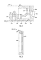
FIG. 5 illustrates the shaft of the roller assembly of FIGS. 2A and 2B.
FIGS. 6A and 6B illustrate an embodiment of a bearing assembly suitable for use with the present invention.
FIG. 7 illustrates a contact region between the bearing assembly of FIGS. 6A and 6B and the shaft of FIG. 5.
FIG. 8 illustrates a cross-sectional view of an outboard portion of the roller assembly illustrated in FIG. 3.
FIG. 9 illustrates a retainer ring for use with certain embodiments of the present invention.
DETAILED DESCRIPTION
The figures and the written description of specific structures and functions are not presented to limit the scope of what has been invented or the scope of the appended claims. Rather, the figures and written description are provided to teach any person skilled in the art to make and use the inventions for which patent protection is sought. Those skilled in the art will appreciate that not all features of a commercial embodiment utilizing one or more of the subject inventions are described or shown for the sake of clarity and understanding. Persons of skill in this art will also appreciate that the development of an actual commercial embodiment incorporating aspects of the present inventions likely will require numerous implementation-specific decisions to achieve the developer's ultimate goal for the commercial embodiment. Such implementation-specific decisions may include, and likely are not limited to, compliance with system-related, business-related, government-related and other constraints, which may vary by specific implementation, location and from time to time. While a developer's efforts might be complex and time-consuming in an absolute sense, such efforts would be, nevertheless, a routine undertaking for those of skill in this art having benefit of this disclosure. It must be understood that the inventions is disclosed and taught herein are susceptible to numerous and various modifications and alternative forms. Lastly, the use of a singular term, such as, but not limited to, “a,” is not intended as limiting of the number of items. Also, the use of relational terms, such as, but not limited to, “top,” “bottom,” “left,” “right,” “upper,” “lower,” “down,” “up,” “side,” and the like are used in the written description for clarity in specific reference to the figures and are not intended to limit the scope of the invention or the appended claims.
In general, Applicants have created a bearing system for a rolling or rotating assembly that is subjected to dynamically varying loads and/or dynamically varying load vectors. One aspect of the inventions comprises a plurality of bearing assemblies or subassemblies, preferably, but not exclusively, having a two-row, double outer race (TDO) configuration. Each bearing assembly may be open or unsealed at at least one end to allow lubrication to flow. Each bearing assembly may have a portion, such as, but not limited to, an inner race, that is preferably interference fit to a component, such as, but not limited to, a stationary shaft. Another portion of the bearing assemblies, such as, but not limited to, an outer race, is preferably interference fit to another component, such as, but not limited to, a rotating structure. The bearing assemblies and at least one of the components cooperating to establish a lubrication pathway for the bearing assemblies. The entire bearing system is configured to react dynamically varying loads and/or load vectors to increase the longevity of bearing system.
Another aspect of the inventions comprises a bearing system having at least one bearing assembly, preferably, but not exclusively, having a TDO configuration. The at least one bearing assembly may have first and second races, each configured to be interference fit to other components. For example, and without limitation, the first race may be interference fit to a stationary component and the second race may be interference fit to a rotating component. Another aspect of the inventions comprises having a greater interference overlap between the first bearing race and the stationary component compared to the interference overlap between the second bearing race is and the rotating component. The entire bearing system is configured to react dynamically varying loads and/or load vectors to increase the longevity of bearing system.
Turning now to a description of at least one of the many possible embodiments benefitting from the present inventions, FIG. 1 provides a side view of a low profile pumping unit 100 that for purposes of this disclosure is exemplary of the type of device that can benefit from the present invention. While this disclosure is provided in the context of a low profile pump unit, neither the applicability of this invention nor the claims sought to protect this invention are limited to a particular type of equipment.
Those of skill in the art will appreciate that a pump jack is used to mechanically lift or pump liquid out of a subterranean well when the well does not have enough natural pressure to force the liquid to the surface. A pump jack converts rotary motion of a crankshaft to a vertical reciprocating motion to drive a downhole pump. A conventional pump jack comprises a walking beam design, and is often referred to as a “horse head” pump jack. A low profile pump jack, such as those offered by Lufkin Industries, is used when the vertical height of the pump jack must be minimized, such as when walking (e.g., rolling) irrigation systems are used or other equipment must be able to physically clear the pump jack.
As illustrated in FIG. 1, a low profile pumping unit 100 comprises a crankshaft 102 and an associated counterweight 104. The low profile pumping unit 100 replaces the walking beam mechanism of the “horse head” pump jack with a flexible load transfer system 106, such as a flexible belt system, and roller drum system 110 that reduces the vertical footprint of the pumping unit 100. As shown in FIG. 1, the flexible belt system 106 is mechanically coupled to the crankshaft 102 for transmitting linear motion to sucker rods string 108, and hence to a downhole pump (not shown). Flexible belt system 106 is illustrated to wrap partially around roller drum system 110 and at its distal end, the flexible belt system 106 is attached to a carrier bar 112 and is ultimately to the sucker rods string 108. While a flexible belt system 106 is illustrated, it will be appreciated the flexible load transfer system 106 may comprise one or more belts, or one or more cables or wire ropes, or any other flexible load transference system that can operatively interact with the roller drum system 110.
It will be appreciated that as the crankshaft 102 makes a 360° revolution, the rotary motion of the crankshaft 102 is converted into axial motion of the sucker rod string 108. Typically, the roller drum system 110 will make a plurality of complete revolutions both forwards and backwards for each single revolution of the crankshaft. For example and by way of example only, the roller drum system 110 illustrated in FIG. 1 may complete about 8 to 12 revolutions for each single revolution of the crankshaft 102. It will be appreciated that the roller drum system 110 (and associated supports) is required to react the load of the sucker rods string 108, which includes, without limitation, the weight of the fluid being pump and other loads. Additionally, it has been found that the direction of the loads reacted by the roller drum system 110 (i.e., the load vectors) vary over time and within each pump stroke. These dynamically varying load vectors may cause the flexible belt system 106 to “walk” off the roller drum system 110 and/or cause premature failure of the bearing system in the roller drum system 110. Thus, sophisticated and substantial bearing systems are required to support the roller drum system 110 and to ensure longevity and efficient operation of the equipment.
Turning now to FIGS. 2A and 2B, a single roller assembly 200 of the type that may be used as part of the roller drum system 110 for a low profile pumping unit 100 illustrated in FIG. 1. FIG. 2A illustrates a roller assembly 200 comprising an outer roller surface 202 and a shaft 204. The outer surface 202 is the surface that contacts the flexible load system 106 illustrated in FIG. 1. FIG. 2B illustrates a partial cross-section of roller assembly 200 comprised of a roller shell 206 of which the outer surface 202 is a portion. A shaft 204 is provided and a bearing assembly 208 allows the roller shell 206 to rotate relative to shaft 204.
FIG. 3 illustrates a more detailed cross-sectional view of one of many possible embodiments of a roller assembly 200. The roller assembly 200 preferably comprises a bearing assembly 208 comprising a plurality of bearing subassemblies 302 and 304. These bearing subassemblies will be described in more detail below. Starting at the left side of FIG. 3, roller assembly 200 comprises a retainer ring 306 that is configured to engage the outside diameter surface of shaft 204. Retainer ring 306 preferably comprises a lubrication fitting 308, such as a Zerk or Alemite® fitting, and has a grease channel configured to allow lubrication, such as grease, to flow from the fitting 308 to other parts of the roller assembly 200. The right side of FIG. 3 shows a second retainer ring 310, which is coupled to the outside diameter surface of shaft 204 and that provides a lubrication channel to a pressure relief fitting 312. It will be appreciated that the lubrication fitting 308 and the pressure relief fitting 312 may be on the left or right side as desired.
Extending between retainer ring 306 and retainer ring 310 is a lubrication pathway 314 comprising a plurality of portions, including pathway 314 a, 314 b, 314 c, 314 d and 314 e. It is preferred that the lubrication pathway 314 comprise at least one channel and at least one gallery that can hold or store a quantity of lubrication. For example, the area between the raised portion 406 (FIG. 4) and the inner surface 402 (identified in FIG. 3 as area 314 c) may be considered a lubrication gallery. Similarly, areas 314 b and 314 d may be considered galleries. It will be appreciated that lubrication (e.g., grease) may be injected into the fitting 308 on a retainer ring 306 and the injected grease will flow (under pressure) through the pathway 314 and until it reaches the pressure relief fitting 312. Lastly, also shown in FIG. 3 are snap rings 316 and 318.
FIG. 4 illustrates a cross-sectional view of the roller shell 204. As shown in FIG. 4, roller shell 206 has an inner surface 402 in which snap ring grooves 404 and 406 is are formed. As will be described in more detail below, the inner surface 402 is configured to have an interference fit with the outer surface of the bearing subassemblies 302 and 304. Preferably, the inner surface 402 of roller shell 206 has a surface finish of about 125 micro inches RA, which readily can be achieved by, for example, milling. Also shown in FIG. 4 is a pre-fit area 408 and 410, which preferably extends from each end portion of roller shell 204 inwardly, preferably approximately about ½ inch. This pre-fit area has an enlarged diameter to aid the installation of the bearing subassemblies during the assembly process. The roller shell 206 may be fabricated from a variety of materials including metals, composites and plastics. In the embodiment illustrated in FIG. 1 the roller shell 206 is fabricated as a metal casting. The outer surface 202 of roller shell 206 may be substantially flat, as illustrated in FIG. 4, or concave or convex as desired to effect the desired performance of the flexible load transfer system 110.
FIG. 5 illustrates an embodiment of a shaft 204 for a single roller assembly 200. Shaft 204 comprises a first bearing area 502 and a second bearing area 504, each configured to receive a bearing subassembly. It is preferred that the surface roughness of the bearing areas be about 32 micro inches RA, such as can be obtained by grinding. Juxtaposed between the two bearing areas 502 and 504 is a raised bearing face 506. Between the raised bearing face 506 and bearing area 502 is a bearing relief area 508, which is discussed in more detail with respect to FIG. 7 below. Between the bearing area 504 and the raised bearing face 506 is another bearing relief area 510.
The shaft illustrated in FIG. 5 is exemplary of a component that may be used for a roller assembly 200 for the low profile pumping jack illustrated in FIG. 1. For this particular embodiment, the shaft 204 is approximately 28 inches long and about 5½ inches in diameter. To react the loads generated by the low profile pumping unit 100, the shaft 204 is preferably fabricated from alloy steel, such as but not limited to ANSI 4145 alloy carbon steel having a Rockwell C hardness of about 25 to about 37. Because of the size and weight of shaft 204, threaded holes 512 and 514 may be manufactured into the ends of shaft 204 to aid the lifting of shaft 204 and assembly of roller assembly 200.
Turning now to FIGS. 6A and 6B, these figures illustrate a type of bearing subassembly 302, 304 that may be used with the roller assembly 200 described in this application. The bearing subassembly illustrated in FIG. 6A is typical of bearings referred to as a railroad bearings. For example and not limitation, the Timken Company offers railroad bearings such as its AP and AP-2 bearing systems, which are suitable, with modification as described below, for use with the present invention. These railroad bearings typically comprise two sets of TDO configured tapered bearings sandwiched between an inner race 604 and an outer race 606. Each end of the bearing subassembly 208 typically comprises seal case 608 and seal wear ring 610.
The “fit” of a bearing to its components can be characterized as loose fit (slip), transition fit, and interference fit (tight). Typically, a loose fit facilitates easy installation. However, too much looseness may allow the bearing to move or creep on the shaft or housing. Such movement can cause excessive wear or vibration and can lead to failure and bearing seizure. An interference fit (or press fit) generally will help prevent unwanted movement, but too much interference overlap may adversely affect the operation of the bearing, such as by altering the internal clearances, and may cause a rise in operating temperature that can cause failure or seizure. The general rule of thumb for bearings has been to use an interference fit between the rotating component and bearing race, and a loose fit on the non-rotating component. For example, when the inner race rotates and the outer race is stationary, conventional rules call for an interference fit at the inner race and a loose fit at the outer race. Alternately, when the inner race is stationary and the outer race rotates, conventional rules call for a loose fit at the inner race and interference fit at the outer race. These conventional rules holds true for both static loads and unbalanced loads. Thus, in the context of the low profile pumping unit 100 illustrated in FIG. 1, the conventional rules of fitment would require a non-interfering “loose” fit between the inner race 604 and the non-rotating shaft 204, and an interference fit between the outer race 606 and the roller shell 206.
Referring to FIG. 5 and FIGS. 6A and 6B, during assembly of a roller assembly 200, a bearing subassembly 302, 304 is press fit onto one of the bearing areas 502, 504 formed on shaft 204. Similarly, a second bearing subassembly 302, 304 is press fit on to the other bearing area. It is been found that to successfully react the dynamically varying loads on the roller assemblies 200 caused by the low profile pumping unit 100, the fit between the shaft 204 and the bearing subassemblies 302, 304 may be tighter than is typical for these types of bearings. For example and not limitation, in the embodiment illustrated in FIG. 1 in which the shaft 204 is stationary, the bearing subassemblies 302, 304 have an inner bearing race 604 with an inner diameter of between about 5 and about 6 inches. The corresponding bearing area 502 and 504 outside diameter on the shaft 204 also may be between about 5 and about 6 inches. It is preferred that the fit between these two components (e.g., between the inner race 604 and the bearing area 502) be an interference fit (in contrast to the conventional non-interfering loose fit) with an interference overlap of more than about 0.0010 inch, inclusive. In other words, it is preferred that the interference fit is tighter than a 0.0010 inch interference overlap, inclusive.
Similarly, it is preferred that there is an interference fit between the outer race 606 of the bearing subassemblies 302, 304 and the inner surface 402 of the roller shell 206. Again, referring to the embodiment illustrated in FIG. 1, the outer race 606 of bearing subassembly 302, 304 may have an outer diameter that varies from about 8 to 9 inches. The corresponding inner surface 402 diameter of roller shell 206 also may be about 8 to about 9 inches. It is preferred that the interference overlap between these two components (i.e., between outer race 606 and roller shell 206) be greater than about 0.0005 inch, inclusive.
Even though it is contrary to conventional rules of bearing fitment, a preferred embodiment useful with equipment experiencing dynamically varying loads and/or load vectors, such as, but not limited to, the low profile pumping unit illustrated in FIG. 1, utilizes more interference overlap at the non-rotating component (i.e., inner race 604 and shaft 204) than is used at the rotating component (i.e., outer race 606 and roller shell 206).
Because of the dynamically varying loads experienced by equipment such as illustrated in FIG. 1, the exemplary bearing illustrated in FIGS. 6A and 6B has been modified to improve its performance. Turning now to FIG. 7 and referring back to FIG. 3, the bearing subassembly 302, 304 is modified by removing the seal case 608 and seal wear ring 610 from the inboard end of the bearing subassembly 302, 304. This modification can be seen most readily by comparing region 320 in FIG. 3 with FIG. 7. FIG. 7 illustrates an enlargement of area 320 in FIG. 3. It is seen that the inner race 604 of bearing subassembly 302, 304 has the seal case 608 and the seal wear ring 610 removed, so that the inner race 604 directly reacts against the raised bearing face 406 of shaft 204. The raised bearing face 506 has a surface that functions as a race seat 702. In the illustration of FIG. 7, the purpose of the bearing seating relief 508 becomes clear. This relief allows for accurate placement of the bearing subassembly 302, 304 on shaft 204, such that the bearing subassembly abuts cleanly to race seat 702.
FIG. 8 illustrates one end of roller assembly 200. In this figure, which shows an outboard end of roller assembly 200, the seal case 608 and the seal wear ring 610 of bearing subassembly 208 are retained. Also shown in this figure is the relationship of snap ring 316 to outer bearing race 606. It is preferred that there be a gap between the snap ring 316, 318 and the face of outer race 606 of at least about 0.050 inch and most preferably at least about 0.063 inch. It can be seen that as lubrication is applied through fitting 308, lubrication flows through lubrication channels 314 to rolling is elements 602 and ultimately to the other retainer ring 308 and pressure relief fitting 312. Thus, one aspect of this invention takes two sealed bearings and modifies them by unsealing the bearings and configuring them to share a lubrication system.
Turning now to FIG. 9, an embodiment of the retainer ring 306, 310 is shown in a one-half cross-sectional view. The retainer ring 306, 310 may be fabricated from material compatible with the material of the shaft 204. For example, if the shaft 204 is made from ANSI 4145 carbon steel, the retainer ring 306, 310 may be fabricated from ANSI 1018 carbon steel. The retainer ring 306, 310 preferably comprises an engagement region 902 configured to accept the seal wear ring 610 as illustrated in FIG. 8. The retainer ring 306, 310 also comprises the threaded portion 904 configured to accept lubrication fitting 308 and/or the pressure relief fitting 312. The threaded portion 904 communicates to a portion of the lubrication channel 314. The retainer ring also comprises an inside diameter surface 906 configured to engage the outside diameter surface of the bearing area 502 or 504 on shaft 204. It is preferred that this inside diameter surface 906 have a surface roughness of approximately 63 micro inches RA, and that the engagement with the bearing area 402 be an interference fit. Alternately, the retainer ring may be held in place by welding, brazing, or by one or more fasteners.
Returning to FIG. 3, it will now be appreciated having the benefit of this application that a roller assembly 200 may be fabricated according to the present invention to react dynamically varying loads of all types of equipment, including, but not limited to the low profile pumping unit illustrated in FIG. 1.
Other and further embodiments utilizing one or more aspects of the inventions described above can be devised without departing from the spirit of Applicant's invention. Further, the various methods and embodiments of the methods of manufacture and assembly of the system, as well as location specifications, can be included in combination with each other to produce variations of the disclosed is methods and embodiments. Discussion of singular elements can include plural elements and vice-versa.
The order of steps can occur in a variety of sequences unless otherwise specifically limited. The various steps described herein can be combined with other steps, interlineated with the stated steps, and/or split into multiple steps. Similarly, elements have been described functionally and can be embodied as separate components or can be combined into components having multiple functions.
The inventions have been described in the context of preferred and other embodiments and not every embodiment of the invention has been described. Obvious modifications and alterations to the described embodiments are available to those of ordinary skill in the art. The disclosed and undisclosed embodiments are not intended to limit or restrict the scope or applicability of the invention conceived of by the Applicants, but rather, in conformity with the patent laws, Applicants intend to fully protect all such modifications and improvements that come within the scope or range of equivalent of the following claims.

Claims (20)

What is claimed is:
1. A bearing system, comprising:
a plurality of bearing assemblies, each assembly open at at least one end to allow the flow of lubrication through the assemblies;
a first component having bearing areas for each of the bearing assemblies, and each bearing area separated from an adjacent bearing area by a raised portion;
each bearing assembly having a first portion configured to interference fit onto its first component bearing area, and a second portion of each bearing assembly contacting the raised portion of the first component;
a first retainer disposed adjacent an end of the first component and adjacent a bearing assembly;
a lubrication pathway defined by the at least one retainer, the bearing assemblies and the first component;
a second component configured to interference fit on to a third portion of each of the bearing assemblies, wherein the first component is stationary and the second component rotates, wherein the fitment between the stationary first component and the bearing assemblies is an interference fit, and wherein the fitment between the bearing assemblies and the stationary and rotating components are both interference fits, and the interference overlap between at least one stationary component and at least one bearing assembly is greater than the interference overlap between the rotating component and the bearing assemblies.
2. The bearing system of claim 1, wherein the first component comprises a stationary shaft.
3. The bearing system of claim 2, wherein the first portion comprises an inner bearing race, and the third portion comprises an outer bearing race.
4. The bearing system of claim 3, wherein the raised portion further comprises at least one seat disposed substantially perpendicular to an associated bearing area, and the second portion comprises a race seat of the inner race.
5. The bearing system of claim 4, further comprising a second retainer disposed adjacent the shaft opposite the first retainer.
6. The bearing system of claim 5, wherein the first and second retainers are configured as retainer rings and are secured to the shaft.
7. The bearing system of claim 6, wherein the first and second retainers are secured to the shaft through interference fit, welding, brazing, or mechanical fastening.
8. The bearing system of claim 1, wherein the bearing assemblies are TDO configured bearings.
9. A bearing system, comprising:
a plurality of bearing assemblies, each assembly open at at least one end to allow the flow of lubrication through the assemblies;
a first component having bearing areas for each of the bearing assemblies, and each bearing area separated from an adjacent bearing area by a raised portion;
each bearing assembly having a first portion configured to interference fit onto its first component bearing area, and a second portion of each bearing assembly contacting the raised portion of the first component;
a first retainer disposed adjacent an end of the first component and adjacent a bearing assembly;
a lubrication pathway defined by the at least one retainer, the bearing assemblies and the first component;
a second component configured to interference fit on to a third portion of each of the bearing assemblies, wherein the first component is stationary and the second component rotates, wherein the fitment between the stationary first component and the bearing assemblies is an interference fit, and wherein the fitment between the bearing assemblies and the stationary and rotating components are both interference fits, and the interference overlap between the stationary components and the bearing assemblies is greater than the interference overlap between the rotating components and the bearing assemblies.
10. The bearing system of claim 9, wherein the bearing assemblies are TDO configured bearings.
11. The bearing system of claim 9, wherein the first and second retainers are secured to the shaft through interference fit, welding, brazing, or mechanical fastening.
12. A bearing system, comprising:
at least one bearing having a first portion configured to interference fit with a first component, and a second portion of the at least one bearing assembly configured to interference fit with a second component;
a first component configured to interference fit with the first portion of the at least one bearing assembly;
a second component configured to interference fit with the second portion of the at least one bearing assembly;
the first component is configured to be stationary and the second component is configured to be rotatable, or the first component is configured be rotatable and the second component is configured to be stationary; and
the interference overlap of the interference fit between the bearing portion and stationary component is greater than the interference overlap of the interference fit between the other bearing portion and rotating component.
13. The bearing system of claim 12, wherein the first component further comprises, a raised portion defining a bearing assembly face seat, and wherein a third portion of the at least one bearing assembly contacts the face seat.
14. The bearing system of claim 13, further comprising a second bearing assembly having first and second portions configured to interference fit with the first and second components, and wherein the bearing assemblies and the first component cooperate to define a lubrication pathway for the bearing assemblies.
15. The bearing system of claim 14, wherein the bearing assemblies are configured in TDO arrangement, wherein the first component is a stationary shaft and the second component is a rotatable element, and further comprising a pair of retainer rings disposed at opposing ends of the shaft and spaced a predetermined distance from each bearing assembly, one retainer ring having a lubrication fitting and the other retainer ring having a pressure relief fitting, and each retainer ring configured to be a part of the lubrication pathway.
16. The bearing system of claim 9, wherein the first component comprises a stationary shaft.
17. The bearing system of claim 16, wherein the first portion comprises an inner bearing race, and the third portion comprises an outer bearing race.
18. The bearing system of claim 17, wherein the raised portion further comprises at least one seat disposed substantially perpendicular to an associated bearing area, and the second portion comprises a race seat of the inner race.
19. The bearing system of claim 18, further comprising a second retainer disposed adjacent the shaft opposite the first retainer.
20. The bearing system of claim 19, wherein the first and second retainers are configured as retainer rings and are secured to the shaft.
US14/503,283 2014-09-30 2014-09-30 Bearing system for dynamically varying loads Active 2035-03-07 US9534634B1 (en)

Priority Applications (4)

Application Number Priority Date Filing Date Title
US14/503,283 US9534634B1 (en) 2014-09-30 2014-09-30 Bearing system for dynamically varying loads
RU2017109395A RU2699594C2 (en) 2014-09-30 2015-09-14 Bearing system for dynamically varying loads (embodiments)
CA2962405A CA2962405C (en) 2014-09-30 2015-09-14 Bearing system for dynamically varying loads
PCT/US2015/049889 WO2016053602A1 (en) 2014-09-30 2015-09-14 Bearing system for dynamically varying loads

Applications Claiming Priority (1)

Application Number Priority Date Filing Date Title
US14/503,283 US9534634B1 (en) 2014-09-30 2014-09-30 Bearing system for dynamically varying loads

Publications (1)

Publication Number Publication Date
US9534634B1 true US9534634B1 (en) 2017-01-03

Family

ID=54150760

Family Applications (1)

Application Number Title Priority Date Filing Date
US14/503,283 Active 2035-03-07 US9534634B1 (en) 2014-09-30 2014-09-30 Bearing system for dynamically varying loads

Country Status (4)

Country Link
US (1) US9534634B1 (en)
CA (1) CA2962405C (en)
RU (1) RU2699594C2 (en)
WO (1) WO2016053602A1 (en)

Citations (25)

* Cited by examiner, † Cited by third party
Publication number Priority date Publication date Assignee Title
US2239891A (en) * 1940-01-20 1941-04-29 Timken Roller Bearing Co Locomotive rod bearing
US2676856A (en) * 1952-08-27 1954-04-27 William R Kohse Movable antifrication bearing for hoisting drums
US2950002A (en) 1957-04-05 1960-08-23 Timken Roller Bearing Co Packaged bearing assemblies
US3021182A (en) 1959-05-29 1962-02-13 Walter H Schnacke Sealed bearing and shaft assembly
FR1437847A (en) * 1964-06-22 1966-05-06 Torrington Co Mounting for multi-row roller bearings
US3499654A (en) * 1966-01-17 1970-03-10 Reliance Electric Co Bearing-shaft sealing structure
US3502375A (en) 1967-09-06 1970-03-24 Farrel Corp Bearing assembly
US3603655A (en) * 1969-10-01 1971-09-07 Timken Co Bearing assembly
US3833277A (en) * 1973-01-12 1974-09-03 Timken Co Bearing assembly with vent means in the bearing thereof
US3940191A (en) * 1972-10-13 1976-02-24 Hitachi, Ltd. Multiple-row roller bearing
US4030785A (en) * 1976-06-21 1977-06-21 Borg-Warner Corporation Bearing cartridge
US4575265A (en) * 1980-05-27 1986-03-11 Reliance Electric Company Seal for shaft bearings
US4692040A (en) * 1985-05-06 1987-09-08 The Torrington Company Multirow roller bearing with seals between the races
US5211484A (en) 1988-11-02 1993-05-18 Quaglia Lawrence D Pressure regulated lubricating system for bearings
US5588752A (en) * 1996-03-04 1996-12-31 Brenco, Incorporated Bearing and journal assembly
JPH11132229A (en) * 1997-10-30 1999-05-18 Nippon Seiko Kk Multi-row taper-roller bearing structure
US5938347A (en) * 1997-09-12 1999-08-17 Gerber Technology, Inc. Bearing lubrication assembly
FR2784147A1 (en) * 1998-09-18 2000-04-07 Ntn Toyo Bearing Co Ltd WHEEL SUPPORT DEVICE
US6312161B1 (en) * 2000-03-31 2001-11-06 The Timken Company End cap for bearing assembly
US6896270B1 (en) * 1999-10-12 2005-05-24 The Timken Company Sealing device for a bearing arrangement
US7121728B2 (en) * 2004-08-04 2006-10-17 Gunite Corporation Seal for a bearing assembly
US7219938B2 (en) * 2003-09-09 2007-05-22 The Timken Company Backing ring for railcar axle
JP5434519B2 (en) * 2009-11-24 2014-03-05 株式会社ジェイテクト Double row tapered roller bearing device
US20140161381A1 (en) 2011-08-19 2014-06-12 The Timken Company Stabilized backing ring and stabilizing ring therefor
US20140254969A1 (en) * 2011-10-05 2014-09-11 Cooper Roller Bearings Co., Ltd. Roller bearing

Family Cites Families (3)

* Cited by examiner, † Cited by third party
Publication number Priority date Publication date Assignee Title
JP2004218689A (en) * 2003-01-10 2004-08-05 Nsk Ltd Pulley unit
WO2006094031A1 (en) * 2005-03-02 2006-09-08 The Timken Company Bearing assembly with a seal-forming bore clip
RU2364761C2 (en) * 2007-10-15 2009-08-20 Общество с ограниченной ответственностью научно-производственное объединение "ИНТЕРМАШ" Journal rolling bearing for first and third wheel pair of locomotive

Patent Citations (25)

* Cited by examiner, † Cited by third party
Publication number Priority date Publication date Assignee Title
US2239891A (en) * 1940-01-20 1941-04-29 Timken Roller Bearing Co Locomotive rod bearing
US2676856A (en) * 1952-08-27 1954-04-27 William R Kohse Movable antifrication bearing for hoisting drums
US2950002A (en) 1957-04-05 1960-08-23 Timken Roller Bearing Co Packaged bearing assemblies
US3021182A (en) 1959-05-29 1962-02-13 Walter H Schnacke Sealed bearing and shaft assembly
FR1437847A (en) * 1964-06-22 1966-05-06 Torrington Co Mounting for multi-row roller bearings
US3499654A (en) * 1966-01-17 1970-03-10 Reliance Electric Co Bearing-shaft sealing structure
US3502375A (en) 1967-09-06 1970-03-24 Farrel Corp Bearing assembly
US3603655A (en) * 1969-10-01 1971-09-07 Timken Co Bearing assembly
US3940191A (en) * 1972-10-13 1976-02-24 Hitachi, Ltd. Multiple-row roller bearing
US3833277A (en) * 1973-01-12 1974-09-03 Timken Co Bearing assembly with vent means in the bearing thereof
US4030785A (en) * 1976-06-21 1977-06-21 Borg-Warner Corporation Bearing cartridge
US4575265A (en) * 1980-05-27 1986-03-11 Reliance Electric Company Seal for shaft bearings
US4692040A (en) * 1985-05-06 1987-09-08 The Torrington Company Multirow roller bearing with seals between the races
US5211484A (en) 1988-11-02 1993-05-18 Quaglia Lawrence D Pressure regulated lubricating system for bearings
US5588752A (en) * 1996-03-04 1996-12-31 Brenco, Incorporated Bearing and journal assembly
US5938347A (en) * 1997-09-12 1999-08-17 Gerber Technology, Inc. Bearing lubrication assembly
JPH11132229A (en) * 1997-10-30 1999-05-18 Nippon Seiko Kk Multi-row taper-roller bearing structure
FR2784147A1 (en) * 1998-09-18 2000-04-07 Ntn Toyo Bearing Co Ltd WHEEL SUPPORT DEVICE
US6896270B1 (en) * 1999-10-12 2005-05-24 The Timken Company Sealing device for a bearing arrangement
US6312161B1 (en) * 2000-03-31 2001-11-06 The Timken Company End cap for bearing assembly
US7219938B2 (en) * 2003-09-09 2007-05-22 The Timken Company Backing ring for railcar axle
US7121728B2 (en) * 2004-08-04 2006-10-17 Gunite Corporation Seal for a bearing assembly
JP5434519B2 (en) * 2009-11-24 2014-03-05 株式会社ジェイテクト Double row tapered roller bearing device
US20140161381A1 (en) 2011-08-19 2014-06-12 The Timken Company Stabilized backing ring and stabilizing ring therefor
US20140254969A1 (en) * 2011-10-05 2014-09-11 Cooper Roller Bearings Co., Ltd. Roller bearing

Non-Patent Citations (3)

* Cited by examiner, † Cited by third party
Title
International Search Report and Written Opinion issued in connection with corresponding PCT Application No. PCT/US2015/049889, dated Jan. 7, 2016.
Timken, "AP Bearings for Industrial Applications", Timken catalog, copyright 2008 by Timken, [retrieved from the internet on Oct. 22, 2014 using ].
Timken, "AP Bearings for Industrial Applications", Timken catalog, copyright 2008 by Timken, [retrieved from the internet on Oct. 22, 2014 using <URL: http://www.timken.com/EN-US/products/Documents/Timken-AP-Bearing-Catalog. pdf>].

Also Published As

Publication number Publication date
WO2016053602A1 (en) 2016-04-07
CA2962405C (en) 2023-08-29
RU2017109395A3 (en) 2019-02-12
RU2017109395A (en) 2018-11-02
RU2699594C2 (en) 2019-09-06
CA2962405A1 (en) 2016-04-07

Similar Documents

Publication Publication Date Title
US8215841B2 (en) Bearing assembly for use in earth drilling
CN110785572B (en) Slinger for roller bearing seals, related assemblies and methods
US20110127725A1 (en) Pressure-balanced floating seal housing assembly and method
JP3200253U (en) Rolling bearing with sealing device
KR20080052361A (en) Bearing roller chain
EP2469110B1 (en) Sealing device and rolling bearing device provided with sealing device
EP2078877A2 (en) Bearing with lubricating means
JP6790555B2 (en) Rolling bearing
US9534634B1 (en) Bearing system for dynamically varying loads
WO2000053959A1 (en) Self-aligning shaft support
CN104011439A (en) Bearing mounted isolator seal
RU191208U1 (en) BEARING BEARING
KR102140855B1 (en) System and method for lubricating plain bearings
CN206723257U (en) A kind of roller bearing for forklift door frame
CN105952647A (en) Rotary compressor
US10082172B2 (en) Plain bearing and/or systems incorporating such bearings
CN211175004U (en) Self-aligning bearing
JP2017190791A (en) Double row bearing
RU210535U1 (en) COVER FOR CONVEYOR ROLLER
JP2015161405A (en) Roller bearing with seal
CN205744937U (en) A kind of bearing outer ring
FI104122B (en) Bearing relief
KR101349802B1 (en) Ball bearing
CN216642785U (en) Reinforced design eccentric snap ring bearing
US11300208B2 (en) Seal assembly with anti-rotation and stability features

Legal Events

Date Code Title Description
AS Assignment

Owner name: LUFKIN INDUSTRIES, LLC, TEXAS

Free format text: ASSIGNMENT OF ASSIGNORS INTEREST;ASSIGNORS:ADAMS, MONTANA Z.;TONEY, DAVID W.;SIGNING DATES FROM 20141107 TO 20141210;REEL/FRAME:034914/0376

STCF Information on status: patent grant

Free format text: PATENTED CASE

MAFP Maintenance fee payment

Free format text: PAYMENT OF MAINTENANCE FEE, 4TH YEAR, LARGE ENTITY (ORIGINAL EVENT CODE: M1551); ENTITY STATUS OF PATENT OWNER: LARGE ENTITY

Year of fee payment: 4

AS Assignment

Owner name: LUFKIN GEARS LLC, TEXAS

Free format text: CHANGE OF NAME;ASSIGNOR:LUFKIN INDUSTRIES, LLC;REEL/FRAME:059844/0110

Effective date: 20201005